EP2268922B2 - Ultrahochdruckpumpe mit alternierendem dreh-/linearantriebsmechanismus - Google Patents
Ultrahochdruckpumpe mit alternierendem dreh-/linearantriebsmechanismus Download PDFInfo
- Publication number
- EP2268922B2 EP2268922B2 EP09726155.6A EP09726155A EP2268922B2 EP 2268922 B2 EP2268922 B2 EP 2268922B2 EP 09726155 A EP09726155 A EP 09726155A EP 2268922 B2 EP2268922 B2 EP 2268922B2
- Authority
- EP
- European Patent Office
- Prior art keywords
- high pressure
- rotor shaft
- hollow rotor
- ultra high
- drive means
- Prior art date
- Legal status (The legal status is an assumption and is not a legal conclusion. Google has not performed a legal analysis and makes no representation as to the accuracy of the status listed.)
- Active
Links
Images


Classifications
-
- F—MECHANICAL ENGINEERING; LIGHTING; HEATING; WEAPONS; BLASTING
- F04—POSITIVE - DISPLACEMENT MACHINES FOR LIQUIDS; PUMPS FOR LIQUIDS OR ELASTIC FLUIDS
- F04B—POSITIVE-DISPLACEMENT MACHINES FOR LIQUIDS; PUMPS
- F04B9/00—Piston machines or pumps characterised by the driving or driven means to or from their working members
- F04B9/02—Piston machines or pumps characterised by the driving or driven means to or from their working members the means being mechanical
-
- B—PERFORMING OPERATIONS; TRANSPORTING
- B24—GRINDING; POLISHING
- B24C—ABRASIVE OR RELATED BLASTING WITH PARTICULATE MATERIAL
- B24C7/00—Equipment for feeding abrasive material; Controlling the flowability, constitution, or other physical characteristics of abrasive blasts
- B24C7/0007—Equipment for feeding abrasive material; Controlling the flowability, constitution, or other physical characteristics of abrasive blasts the abrasive material being fed in a liquid carrier
-
- B—PERFORMING OPERATIONS; TRANSPORTING
- B24—GRINDING; POLISHING
- B24C—ABRASIVE OR RELATED BLASTING WITH PARTICULATE MATERIAL
- B24C9/00—Appurtenances of abrasive blasting machines or devices, e.g. working chambers, arrangements for handling used abrasive material
-
- B—PERFORMING OPERATIONS; TRANSPORTING
- B26—HAND CUTTING TOOLS; CUTTING; SEVERING
- B26F—PERFORATING; PUNCHING; CUTTING-OUT; STAMPING-OUT; SEVERING BY MEANS OTHER THAN CUTTING
- B26F3/00—Severing by means other than cutting; Apparatus therefor
- B26F3/004—Severing by means other than cutting; Apparatus therefor by means of a fluid jet
-
- F—MECHANICAL ENGINEERING; LIGHTING; HEATING; WEAPONS; BLASTING
- F04—POSITIVE - DISPLACEMENT MACHINES FOR LIQUIDS; PUMPS FOR LIQUIDS OR ELASTIC FLUIDS
- F04B—POSITIVE-DISPLACEMENT MACHINES FOR LIQUIDS; PUMPS
- F04B1/00—Multi-cylinder machines or pumps characterised by number or arrangement of cylinders
- F04B1/02—Multi-cylinder machines or pumps characterised by number or arrangement of cylinders having two cylinders
-
- F—MECHANICAL ENGINEERING; LIGHTING; HEATING; WEAPONS; BLASTING
- F04—POSITIVE - DISPLACEMENT MACHINES FOR LIQUIDS; PUMPS FOR LIQUIDS OR ELASTIC FLUIDS
- F04B—POSITIVE-DISPLACEMENT MACHINES FOR LIQUIDS; PUMPS
- F04B11/00—Equalisation of pulses, e.g. by use of air vessels; Counteracting cavitation
- F04B11/005—Equalisation of pulses, e.g. by use of air vessels; Counteracting cavitation using two or more pumping pistons
-
- F—MECHANICAL ENGINEERING; LIGHTING; HEATING; WEAPONS; BLASTING
- F04—POSITIVE - DISPLACEMENT MACHINES FOR LIQUIDS; PUMPS FOR LIQUIDS OR ELASTIC FLUIDS
- F04B—POSITIVE-DISPLACEMENT MACHINES FOR LIQUIDS; PUMPS
- F04B11/00—Equalisation of pulses, e.g. by use of air vessels; Counteracting cavitation
- F04B11/005—Equalisation of pulses, e.g. by use of air vessels; Counteracting cavitation using two or more pumping pistons
- F04B11/0058—Equalisation of pulses, e.g. by use of air vessels; Counteracting cavitation using two or more pumping pistons with piston speed control
-
- F—MECHANICAL ENGINEERING; LIGHTING; HEATING; WEAPONS; BLASTING
- F04—POSITIVE - DISPLACEMENT MACHINES FOR LIQUIDS; PUMPS FOR LIQUIDS OR ELASTIC FLUIDS
- F04B—POSITIVE-DISPLACEMENT MACHINES FOR LIQUIDS; PUMPS
- F04B17/00—Pumps characterised by combination with, or adaptation to, specific driving engines or motors
- F04B17/03—Pumps characterised by combination with, or adaptation to, specific driving engines or motors driven by electric motors
-
- F—MECHANICAL ENGINEERING; LIGHTING; HEATING; WEAPONS; BLASTING
- F04—POSITIVE - DISPLACEMENT MACHINES FOR LIQUIDS; PUMPS FOR LIQUIDS OR ELASTIC FLUIDS
- F04B—POSITIVE-DISPLACEMENT MACHINES FOR LIQUIDS; PUMPS
- F04B23/00—Pumping installations or systems
- F04B23/04—Combinations of two or more pumps
- F04B23/06—Combinations of two or more pumps the pumps being all of reciprocating positive-displacement type
-
- F—MECHANICAL ENGINEERING; LIGHTING; HEATING; WEAPONS; BLASTING
- F04—POSITIVE - DISPLACEMENT MACHINES FOR LIQUIDS; PUMPS FOR LIQUIDS OR ELASTIC FLUIDS
- F04B—POSITIVE-DISPLACEMENT MACHINES FOR LIQUIDS; PUMPS
- F04B41/00—Pumping installations or systems specially adapted for elastic fluids
- F04B41/06—Combinations of two or more pumps
-
- F—MECHANICAL ENGINEERING; LIGHTING; HEATING; WEAPONS; BLASTING
- F04—POSITIVE - DISPLACEMENT MACHINES FOR LIQUIDS; PUMPS FOR LIQUIDS OR ELASTIC FLUIDS
- F04B—POSITIVE-DISPLACEMENT MACHINES FOR LIQUIDS; PUMPS
- F04B49/00—Control, e.g. of pump delivery, or pump pressure of, or safety measures for, machines, pumps, or pumping installations, not otherwise provided for, or of interest apart from, groups F04B1/00 - F04B47/00
- F04B49/06—Control using electricity
-
- F—MECHANICAL ENGINEERING; LIGHTING; HEATING; WEAPONS; BLASTING
- F04—POSITIVE - DISPLACEMENT MACHINES FOR LIQUIDS; PUMPS FOR LIQUIDS OR ELASTIC FLUIDS
- F04B—POSITIVE-DISPLACEMENT MACHINES FOR LIQUIDS; PUMPS
- F04B49/00—Control, e.g. of pump delivery, or pump pressure of, or safety measures for, machines, pumps, or pumping installations, not otherwise provided for, or of interest apart from, groups F04B1/00 - F04B47/00
- F04B49/06—Control using electricity
- F04B49/065—Control using electricity and making use of computers
-
- F—MECHANICAL ENGINEERING; LIGHTING; HEATING; WEAPONS; BLASTING
- F04—POSITIVE - DISPLACEMENT MACHINES FOR LIQUIDS; PUMPS FOR LIQUIDS OR ELASTIC FLUIDS
- F04B—POSITIVE-DISPLACEMENT MACHINES FOR LIQUIDS; PUMPS
- F04B49/00—Control, e.g. of pump delivery, or pump pressure of, or safety measures for, machines, pumps, or pumping installations, not otherwise provided for, or of interest apart from, groups F04B1/00 - F04B47/00
- F04B49/20—Control, e.g. of pump delivery, or pump pressure of, or safety measures for, machines, pumps, or pumping installations, not otherwise provided for, or of interest apart from, groups F04B1/00 - F04B47/00 by changing the driving speed
-
- F—MECHANICAL ENGINEERING; LIGHTING; HEATING; WEAPONS; BLASTING
- F04—POSITIVE - DISPLACEMENT MACHINES FOR LIQUIDS; PUMPS FOR LIQUIDS OR ELASTIC FLUIDS
- F04B—POSITIVE-DISPLACEMENT MACHINES FOR LIQUIDS; PUMPS
- F04B53/00—Component parts, details or accessories not provided for in, or of interest apart from, groups F04B1/00 - F04B23/00 or F04B39/00 - F04B47/00
- F04B53/08—Cooling; Heating; Preventing freezing
-
- F—MECHANICAL ENGINEERING; LIGHTING; HEATING; WEAPONS; BLASTING
- F04—POSITIVE - DISPLACEMENT MACHINES FOR LIQUIDS; PUMPS FOR LIQUIDS OR ELASTIC FLUIDS
- F04B—POSITIVE-DISPLACEMENT MACHINES FOR LIQUIDS; PUMPS
- F04B53/00—Component parts, details or accessories not provided for in, or of interest apart from, groups F04B1/00 - F04B23/00 or F04B39/00 - F04B47/00
- F04B53/10—Valves; Arrangement of valves
-
- F—MECHANICAL ENGINEERING; LIGHTING; HEATING; WEAPONS; BLASTING
- F04—POSITIVE - DISPLACEMENT MACHINES FOR LIQUIDS; PUMPS FOR LIQUIDS OR ELASTIC FLUIDS
- F04B—POSITIVE-DISPLACEMENT MACHINES FOR LIQUIDS; PUMPS
- F04B53/00—Component parts, details or accessories not provided for in, or of interest apart from, groups F04B1/00 - F04B23/00 or F04B39/00 - F04B47/00
- F04B53/14—Pistons, piston-rods or piston-rod connections
-
- F—MECHANICAL ENGINEERING; LIGHTING; HEATING; WEAPONS; BLASTING
- F04—POSITIVE - DISPLACEMENT MACHINES FOR LIQUIDS; PUMPS FOR LIQUIDS OR ELASTIC FLUIDS
- F04B—POSITIVE-DISPLACEMENT MACHINES FOR LIQUIDS; PUMPS
- F04B53/00—Component parts, details or accessories not provided for in, or of interest apart from, groups F04B1/00 - F04B23/00 or F04B39/00 - F04B47/00
- F04B53/16—Casings; Cylinders; Cylinder liners or heads; Fluid connections
-
- H—ELECTRICITY
- H02—GENERATION; CONVERSION OR DISTRIBUTION OF ELECTRIC POWER
- H02K—DYNAMO-ELECTRIC MACHINES
- H02K7/00—Arrangements for handling mechanical energy structurally associated with dynamo-electric machines, e.g. structural association with mechanical driving motors or auxiliary dynamo-electric machines
- H02K7/06—Means for converting reciprocating motion into rotary motion or vice versa
-
- F—MECHANICAL ENGINEERING; LIGHTING; HEATING; WEAPONS; BLASTING
- F04—POSITIVE - DISPLACEMENT MACHINES FOR LIQUIDS; PUMPS FOR LIQUIDS OR ELASTIC FLUIDS
- F04B—POSITIVE-DISPLACEMENT MACHINES FOR LIQUIDS; PUMPS
- F04B2201/00—Pump parameters
- F04B2201/02—Piston parameters
- F04B2201/0201—Position of the piston
-
- F—MECHANICAL ENGINEERING; LIGHTING; HEATING; WEAPONS; BLASTING
- F04—POSITIVE - DISPLACEMENT MACHINES FOR LIQUIDS; PUMPS FOR LIQUIDS OR ELASTIC FLUIDS
- F04B—POSITIVE-DISPLACEMENT MACHINES FOR LIQUIDS; PUMPS
- F04B2201/00—Pump parameters
- F04B2201/02—Piston parameters
- F04B2201/0202—Linear speed of the piston
-
- F—MECHANICAL ENGINEERING; LIGHTING; HEATING; WEAPONS; BLASTING
- F04—POSITIVE - DISPLACEMENT MACHINES FOR LIQUIDS; PUMPS FOR LIQUIDS OR ELASTIC FLUIDS
- F04B—POSITIVE-DISPLACEMENT MACHINES FOR LIQUIDS; PUMPS
- F04B2203/00—Motor parameters
- F04B2203/02—Motor parameters of rotating electric motors
- F04B2203/0201—Current
-
- F—MECHANICAL ENGINEERING; LIGHTING; HEATING; WEAPONS; BLASTING
- F04—POSITIVE - DISPLACEMENT MACHINES FOR LIQUIDS; PUMPS FOR LIQUIDS OR ELASTIC FLUIDS
- F04B—POSITIVE-DISPLACEMENT MACHINES FOR LIQUIDS; PUMPS
- F04B2203/00—Motor parameters
- F04B2203/02—Motor parameters of rotating electric motors
- F04B2203/0202—Voltage
-
- F—MECHANICAL ENGINEERING; LIGHTING; HEATING; WEAPONS; BLASTING
- F04—POSITIVE - DISPLACEMENT MACHINES FOR LIQUIDS; PUMPS FOR LIQUIDS OR ELASTIC FLUIDS
- F04B—POSITIVE-DISPLACEMENT MACHINES FOR LIQUIDS; PUMPS
- F04B2203/00—Motor parameters
- F04B2203/02—Motor parameters of rotating electric motors
- F04B2203/0209—Rotational speed
-
- F—MECHANICAL ENGINEERING; LIGHTING; HEATING; WEAPONS; BLASTING
- F04—POSITIVE - DISPLACEMENT MACHINES FOR LIQUIDS; PUMPS FOR LIQUIDS OR ELASTIC FLUIDS
- F04B—POSITIVE-DISPLACEMENT MACHINES FOR LIQUIDS; PUMPS
- F04B2205/00—Fluid parameters
- F04B2205/03—Pressure in the compression chamber
Definitions
- the invention also relates to an ultra high pressure pump, in particular an ultra high pressure waterjet pump for use in waterjet cutting apparatus, according to the preamble of claim 1.
- Waterjet cutting apparatus has been used for some years to cut a variety of materials such as steel, aluminium, glass, marble, plastics, rubber, cork and wood.
- the work piece is placed over a shallow tank of water and a cutting head expelling a cutting jet is accurately displaced across the work piece to complete the desired cut.
- the cutting action is carried out by the combination of a very high pressure jet (up to 620 MPa (90,000 psi)) of water entrained with fine particles of abrasive material, usually sand, that causes the cutting action.
- the water and sand that exit the cutting head are collected beneath the work piece in the tank.
- UHP waterjets are used to define a process where water is pressurised above 345 MPa (50000psi) and then used as a cutting tool.
- the high pressure water is forced through a very small hole which is typically between 0.1mm and 0.5mm in diameter in a jewel which is often ruby, sapphire or diamond.
- Intensifier pumps are usually hydraulic pumps which can pressurise oil up to approximately 20 MPa (3000psi). The oil is then forced into a cylinder which has a large piston attached to a smaller piston which is 1/20 the area of the hydraulic piston. The secondary piston is positioned in a cylinder which is filled with water. As the hydraulic piston is forced back and forth it forces the water piston to reciprocate creating a pressure some twenty times that of the hydraulic system. Although these systems are fairly reliably, they are inefficient due to the need to drive the hydraulic system. Typically, these pumps run at about 55% efficiency.
- a more efficient pump is the direct drive crank shaft pump where a motor is coupled directly to a crank shaft.
- the crank shaft rotates whilst driving a number of small pistons, usually three, to reciprocate in cylinders thus pressurising the water.
- These pumps are fairly efficient, typically above 80%, when they are utilising the water being pressurised but they cannot store and hold pressure which means that when the waterjet apparatus is not actually cutting, the pressurised water is expelled from a release valve which means that the pumps use a similar amount of power whether sitting idle or in a cutting operation.
- These pumps are not as reliable as the intensifier pumps due to the high piston speed and the number of strokes required to make the same volume of ultra high pressure water.
- US patent no. 6,139,288 discloses a pump including a threaded transmission shaft embraced and driven by a rotation shaft. At ends of the rotation shaft are nuts cooperable with the transmission shaft. The pump can deliver 196 MPa.
- US patent no. 5,704,250 discloses a ball screw drive with dynamically adjustable preload.
- the mechanism comprises a housing located around a stator.
- the housing comprises a water cooled jacket.
- US patent no. 4,276,003 discloses a reciprocating piston pump system with screw drive.
- the pump includes a piston rod.
- the piston carries an anti-rotation device.
- the anti-rotation device has a pair of rollers at its ends. The rollers bear against a pair of tracks to prevent rotation of the piston rod.
- US patent no. 5,993,181 discloses a pump assembly comprising two piston pumps wherein the speed of one piston is greater than the speed of the other piston whilst the other piston is reversing.
- the present invention is defined by the features of claim 1.
- the drive means is connected to pistons at both ends of the shaft, each piston being adapted to complete reciprocal motion within associated cylinders thus defined two pumping chambers.
- the servo motor is located within a cylindrical housing that is in turn encased in a water cooling jacket.
- the servo motor includes an encoder to count the frequency of rotation of the rotor shaft, the encoder being coupled to the control of the motor via a feedback loop.
- the drive means comprises a linearly fixed roller nut that is threadedly engaged with the rotor shaft.
- the roller nut threadedly engaging a screw whereby axial rotation of the rotor shaft and roller nut imparts reciprocal motion to the screw.
- the screw extends out each end of the pump to be coupled to the pistons.
- a drive mechanism comprising a controller coupled to a servo motor having a stator coaxially mounted around a hollow rotor, the hollow rotor including drive means co-axially coupled to an output shaft whereby the drive means converts rotational movement of the rotor to linear displacement of the shaft and an encoder to measure movement of the rotor or output shaft and send a feedback signal proportional to the movement to the controller.
- a linear actuator comprising a servo motor having a stator coaxially mounted around a hollow rotor, a drive member in engagement with the interior of the rotor, the drive member being constrained against linear movement and threadingly supporting a shaft to impart linear displacement of the shaft, and an encoder monitoring movement of the drive member or shaft and arranged to send a feedback signal to the servo motor whereby the operation and control of the servo motor causes controlled linear displacement of the shaft.
- the invention of the subject application is, in essence, a drive mechanism which can be used in a wide variety of scenarios where close careful control of the drive is necessary.
- a linear actuator that can be used to replace hydraulic cylinders, which are inherently inefficient, noisy, dirty, and not precise, in a wide variety of engineering applications such as presses, robotics, materials handling and other similar uses. It is the use of a servo motor with a closed feedback loop that provides the opportunity to closely and carefully control the drive .
- the drive mechanism When the drive mechanism is used in a pump it comprises a servo motor that drives two reciprocating pistons that project from either end of the pump to operate within cylinders to pressurise water introduced into the cylinders to pressures of greater than 345 MPa (50000 psi).
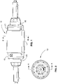
- the pump 10 comprises a cylindrical housing 11 that is encased within a cylindrical water cooled jacket 12.
- the housing 11 has end flanges 16, 17 that support a hollow rotor shaft 15 about windings 19 of a servo motor.
- One end 13 of the rotor shaft 15 is supported by an annular bearing 14 located between the housing 11 and the shaft 15.
- the other end 18 of the rotor shaft 15 supports a bearing housing 27 that supports a bearing 28.
- the rotor shaft 15 houses a roller nut 30 which is in turn threadedly engaged onto an elongated screw 31.
- the roller nut 30 is in direct engagement with the interior of the shaft and is constrained against linear movement to rotate with the rotor shaft 15.
- the screw 31 has a threaded exterior 20 with a flat 21 machined on one end 22.
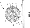
- the flat 21 supports linear bearings 23, 24 which run on elongate spaced apart rails 25, 26 ( Figure 4 ).
- the rails 25, 26 extend past the end flange 17 of the housing 11.
- the end 15 of the rotor shaft supporting the bearing 28 supports an externally positioned encoder 80.
- the ends of the screw 31 are coupled to pistons 50 and 51 that are arranged to reciprocate within associated cylinders 54 and 55.
- the heads 56, 57 of the pistons define with the cylinders 54, 55 compression chambers 58, 59.
- the rotor shaft 15 is located within the casing 11 about the spaced bearings 13 and 28 to facilitate axial rotation of the shaft 15 relative to the casing 11.
- the end flanges 16, 17 are bolted and secured to the casing 11 to hold the assembly together and the projecting pistons 50, 51 are enclosed within stainless steel mounts 65, 66 that support the cylinders 54, 55.
- the servo motor causes the rotor shaft 15 to rotate which in turn rotates the roller nut 30 which is constrained from axial movement thus meaning that the screw 31 moves linearly within the roller nut 30.
- the screw 31 can thus be caused to reciprocate back and forth to give the reciprocating motion to the pistons 50, 51 to in turn pressurise the water that is introduced into the compression chambers 58, 59 via water inlets 60 to effect high pressure delivery of water from the outlets 61 at pressures greater than 3447,3786 bar (50,000psi).
- Each cylinder 54, 55 has a low pressure water inlet 73 controlled by a check valve 74 communicating with the compression chambers 58, 59 at a 45° angle to axis of the cylinder.
- a high pressure outlet 75 is positioned co- axial to the end of the cylinder and includes a check valve 76.
- High pressure seals 70, 71 are positioned between the inner ends of the cylinders 54, 55 and the pistons 50, 51 to prevent back pressure.
- the servo motor is controlled by a computer numerical controller (CNC) .
- CNC computer numerical controller
- the servo motor which is used in the preferred embodiment is a brushless DC servo motor operating on a DC voltage of about 600 volts. This is a motor which is commonly used in machine tools and has traditionally been very controllable to provide the precision which is required in such machine tool applications.
- the pistons have a stroke of about 175mm and reciprocate at approximately 120 strokes per minute. The movement of a piston in one direction lasts about 0.8 seconds.
- the pump is designed to operate in the most efficient mode with the delivery of water at 2L per minute but it could operate with a delivery of up to 4L per minute though this would reduce the life of the pump.
- the servo drive pump described above is far more efficient than an intensifier pump while still offering the desired ability to be able to store and hold pressure while not cutting, thus using only minimal power.
- the rotor shaft is designed to run at about 1500rpm and the piston is about 180mm in length running in a bore with a head diameter of 14mm. This makes the whole assembly small, light and considerably quieter than an intensifier pump.
- the servo drive system is also very responsive and pressures can be adjusted within milliseconds with infinite control.
- FIG. 5 is an illustration of a closed loop showing the control of a linear actuator.
- the computer numerical controller 81 drives a position controller 82 that in turn is coupled to a velocity controller 83 which in turn is coupled to a current controller 84 to drive the servo motor which becomes the linear actuator.
- the encoder 80 sends two feedback signals, namely a velocity feedback signal that is fed to the velocity controller and a position feedback signal that is fed to the position controller.
- the computer controlling operation of the servo motor by monitoring the feedback signals provides an extremely positive and accurate control of the linear displacement of the output shaft which means that the linear actuator can be used to replace the hydraulic cylinders conventionally used in applications such as heavy duty presses, injection moulding machines, lifting tables and platforms or high load cutting or polishing machines.
- the linear actuator is particularly compact and thus is especially useful where there is a need for increased control of speed, position or force and limited space is available.
Landscapes
- Engineering & Computer Science (AREA)
- Mechanical Engineering (AREA)
- General Engineering & Computer Science (AREA)
- Power Engineering (AREA)
- Life Sciences & Earth Sciences (AREA)
- Forests & Forestry (AREA)
- Computer Hardware Design (AREA)
- Reciprocating Pumps (AREA)
- Details Of Reciprocating Pumps (AREA)
- Rotary Pumps (AREA)
- Compressors, Vaccum Pumps And Other Relevant Systems (AREA)
Claims (9)
- Ultrahochdruckpumpe (10), umfassend: einen Servomotor (15, 19) ;eine Rotorhohlwelle (15);ein Antriebsmittel (30);zwei Kolben (50, 51);zwei Zylinder (54, 55); undzwei Pumpkammern (58, 59);wobei der Servomotor angepasst ist, um die Rotorhohlwelle axial in wechselnde Richtungen zu drehen;wobei der Servomotor einen Stator (19) aufweist, der koaxial um die Rotorhohlwelle positioniert ist;wobei die Rotorhohlwelle (15) koaxial an das Antriebsmittel gekoppelt ist;wobei das Antriebsmittel angepasst ist, um eine axiale Drehung in eine wechselseitige Verschiebung umzuwandeln und umfassend eine Schraube (31), die mit einer linear fixierten Mutter (30) in Eingriff steht, wobei die axiale Drehung der Rotorhohlwelle (15) eine lineare Bewegung der Schraube (31) vermittelt;wobei der Servomotor einen Codierer (80) einschließt, um eine Bewegung der Rotorhohlwelle oder des Antriebsmittels zu überwachen;wobei der Codierer an den Servomotor über eine geschlossene Rückkopplungsschleife gekoppelt ist;wobei die Kolben (50, 51) an gegenüberliegende Enden der Schraube (31) gekoppelt sind, wobei jeder Kolben (50, 51) angepasst ist, um eine wechselseitige Bewegung in einem assoziierten Zylinder (54, 55) abzuschließen, wodurch die zwei Pumpkammern (58, 59) definiert werden;wobei das Antriebsmittel an die Kolben gekoppelt ist, sodass eine wechselnde Drehung der Rotorhohlwelle zu einer wechselseitigen linearen Verschiebung der Kolben führt, um Fluid in den Pumpkammern unter Druck zu setzen;dadurch gekennzeichnet, dass sich die Mutter (30) des Antriebsmittels in der Rotorhohlwelle (15) befindet und an eine Innenseite davon gekoppelt ist, wobei die Mutter eine Rollenmutter ist.
- Ultrahochdruckpumpe nach Anspruch 1, wobei der Codierer ein Geschwindigkeitsrückkopplungssignal und ein Positionsrückkopplungssignal überträgt.
- Ultrahochdruckpumpe nach Anspruch 1 oder 2, wobei sich der Stator in einem zylindrischen Gehäuse (11) befindet und das Gehäuse von einem Wasserkühlmantel (12) umschlossen ist.
- Ultrahochdruckpumpe nach Anspruch 3, wobei das Gehäuse, der Kühlmantel, der Stator, die Rotorhohlwelle und das Antriebsmittel jeweils koaxial sind.
- Ultrahochdruckpumpe nach einem der Ansprüche 1 bis 4, wobei die Schraube von Linearlagern (23, 24) gestützt wird, die jeweils auf länglichen Schienen (25, 26) gestützt werden, wobei die Linearlager eine Drehung der Schraube verhindern, während eine Längsbewegung der Schraube vereinfacht wird.
- Ultrahochdruckpumpe nach Anspruch 5, wobei ein Ende der Rotorhohlwelle von einem Ringlager (14) gestützt wird und die Schienen durch das Ringlager hindurchgehen.
- Ultrahochdruckpumpe nach einem der Ansprüche 1 bis 6, wobei jeder Zylinder einen Niederdruckwassereinlass (73) hat, der von einem Niederdruckrückschlagventil (74) gesteuert wird, welches mit den Pumpenkammern (58, 59) in einem 45°-Winkel zur Zylinderachse kommuniziert, und einen Hochdruckauslass (75), der koaxial mit dem Ende des Zylinders positioniert ist und von einem Hochdruckrückschlagventil (76) gesteuert wird.
- Wasserstrahlschneideinrichtung, einschließend:einen Schneidkopf zum Ausstoßen eines Schneidstrahls; undangeordnet, um dem Schneidkopf Fluid zuzuführen, die Pumpe nach einem der Ansprüche 1 bis 7.
- Wasserstrahlschneideinrichtung nach Anspruch 8, wobei der Schneidkopf und die Pumpe konfiguriert sind, damit die Pumpe das Fluid dem Schneidkopf mit Drücken größer als 345 MPa (50.000 psi) zuführen kann.
Priority Applications (1)
| Application Number | Priority Date | Filing Date | Title |
|---|---|---|---|
| EP19157449.0A EP3501734B1 (de) | 2008-03-26 | 2009-03-24 | Ultrahochdruckpumpe mit alternierendem dreh-/ linearantriebsmechanismus |
Applications Claiming Priority (2)
| Application Number | Priority Date | Filing Date | Title |
|---|---|---|---|
| AU2008901442A AU2008901442A0 (en) | 2008-03-26 | High Pressure Pump | |
| PCT/AU2009/000334 WO2009117765A1 (en) | 2008-03-26 | 2009-03-24 | Ultra high pressure pump with an alternating rotation to linear displacement drive mechanism |
Related Child Applications (2)
| Application Number | Title | Priority Date | Filing Date |
|---|---|---|---|
| EP19157449.0A Division-Into EP3501734B1 (de) | 2008-03-26 | 2009-03-24 | Ultrahochdruckpumpe mit alternierendem dreh-/ linearantriebsmechanismus |
| EP19157449.0A Division EP3501734B1 (de) | 2008-03-26 | 2009-03-24 | Ultrahochdruckpumpe mit alternierendem dreh-/ linearantriebsmechanismus |
Publications (4)
| Publication Number | Publication Date |
|---|---|
| EP2268922A1 EP2268922A1 (de) | 2011-01-05 |
| EP2268922A4 EP2268922A4 (de) | 2017-04-12 |
| EP2268922B1 EP2268922B1 (de) | 2019-02-20 |
| EP2268922B2 true EP2268922B2 (de) | 2022-08-24 |
Family
ID=41112849
Family Applications (2)
| Application Number | Title | Priority Date | Filing Date |
|---|---|---|---|
| EP09726155.6A Active EP2268922B2 (de) | 2008-03-26 | 2009-03-24 | Ultrahochdruckpumpe mit alternierendem dreh-/linearantriebsmechanismus |
| EP19157449.0A Active EP3501734B1 (de) | 2008-03-26 | 2009-03-24 | Ultrahochdruckpumpe mit alternierendem dreh-/ linearantriebsmechanismus |
Family Applications After (1)
| Application Number | Title | Priority Date | Filing Date |
|---|---|---|---|
| EP19157449.0A Active EP3501734B1 (de) | 2008-03-26 | 2009-03-24 | Ultrahochdruckpumpe mit alternierendem dreh-/ linearantriebsmechanismus |
Country Status (7)
| Country | Link |
|---|---|
| US (5) | US9212657B2 (de) |
| EP (2) | EP2268922B2 (de) |
| JP (1) | JP2011515616A (de) |
| CN (1) | CN101970875B (de) |
| AU (1) | AU2009227976A1 (de) |
| ES (1) | ES2726374T5 (de) |
| WO (1) | WO2009117765A1 (de) |
Families Citing this family (31)
| Publication number | Priority date | Publication date | Assignee | Title |
|---|---|---|---|---|
| EP2268922B2 (de) | 2008-03-26 | 2022-08-24 | Quantum Servo Pumping Technologies Pty Ltd | Ultrahochdruckpumpe mit alternierendem dreh-/linearantriebsmechanismus |
| ES2769552T3 (es) | 2010-09-13 | 2020-06-26 | Quantum Servo Pumping Tech Pty Ltd | Bomba de ultra alta presión |
| JP5766493B2 (ja) * | 2011-04-13 | 2015-08-19 | 三菱重工業株式会社 | アブレイシブウォータージェット加工装置 |
| CN102886746B (zh) * | 2011-12-17 | 2015-07-15 | 徐州浩通水射流科技有限公司 | 一种球电机驱动的磨料水射流关节 |
| CN102536720A (zh) * | 2011-12-23 | 2012-07-04 | 四川盛堡机电科技有限责任公司 | 一种立式双动式旋压泵 |
| HU229852B1 (en) * | 2012-08-15 | 2014-10-28 | Hibar Systems Ltd Richmond Hill | Electronically controlled and driven linear pump actuator |
| CN103199649B (zh) * | 2013-02-18 | 2016-06-15 | 成都瑞迪机械实业有限公司 | 机电一体化直线驱动装置 |
| DE102013111169C5 (de) * | 2013-10-09 | 2018-03-29 | Zwick Gmbh & Co. Kg | Prüfzylinder und Prüfmaschine |
| TWI531724B (zh) * | 2013-11-06 | 2016-05-01 | Cvc Technologies Inc | Linear fluid pressurized pump |
| WO2015127497A1 (en) * | 2014-02-26 | 2015-09-03 | Techni Waterjet Pty Ltd | Linear actuator |
| ITUB20161067A1 (it) * | 2016-02-25 | 2017-08-25 | Umbragroup S P A | Attuatore elettromeccanico lineare, preferibilmente per taglio ad acqua |
| CN106272097A (zh) * | 2016-09-03 | 2017-01-04 | 安徽华利达户外用品有限公司 | 一种高压加磨料型木材切割枪 |
| US20180076691A1 (en) * | 2016-09-12 | 2018-03-15 | Ford Global Technologies, Llc | Device thermal management assembly and method |
| IT201600117208A1 (it) * | 2016-11-21 | 2018-05-21 | Interpump Group S P A | Gruppo pompante |
| US10630138B2 (en) * | 2017-09-13 | 2020-04-21 | Schaeffler Technologies AG & Co. KG | Reciprocating ramp motor |
| AU2018204532B1 (en) | 2017-11-06 | 2019-06-13 | Quantum Servo Pumping Technologies Pty Ltd | Fault detection and prediction |
| AU2018204487B1 (en) | 2017-11-10 | 2019-05-30 | Quantum Servo Pumping Technologies Pty Ltd | Pumping systems |
| US11519402B2 (en) | 2017-12-21 | 2022-12-06 | Haskel International, Llc | Electric driven gas booster |
| CN108799045B (zh) * | 2018-07-31 | 2024-05-10 | 江苏钧微动力科技有限公司 | 一种矢量控制泵 |
| WO2020037283A1 (en) * | 2018-08-17 | 2020-02-20 | S.P.M. Flow Control, Inc. | Actuator for a reciprocating pump |
| CN109185508B (zh) * | 2018-09-29 | 2024-12-06 | 佛山市能博机电有限公司 | 一种用于水刀的进出水阀装置 |
| CN111852810B (zh) * | 2019-04-30 | 2024-11-26 | 浙江工业大学 | 二维压力伺服变量泵 |
| DE102019208707A1 (de) | 2019-06-14 | 2020-12-17 | Thyssenkrupp Ag | Vorrichtung und Verfahren zum Bereitstellen von druckbeaufschlagtem Medium zur Injektion in einen Hochdruck-Prozess |
| CN113084716B (zh) * | 2019-12-23 | 2022-11-08 | 张英 | 水砂旋转接头及喷砂枪 |
| US12565877B2 (en) | 2020-03-31 | 2026-03-03 | Graco Minnesota Inc. | Electrically operated linear pump and pump drive |
| KR20220156622A (ko) | 2020-03-31 | 2022-11-25 | 그라코 미네소타 인크. | 전기 작동식 변위 펌프 |
| AU2021246060B2 (en) | 2020-03-31 | 2026-04-09 | Graco Minnesota Inc. | Electrically operated pump for a plural component spray system |
| DE102020206493A1 (de) * | 2020-05-25 | 2021-11-25 | Hyundai Motor Company | Kraftstoffpumpe für ein Flüssigkraftstoff-Einspritzsystem eines Kraftfahrzeugs |
| DE102020126702A1 (de) | 2020-10-12 | 2022-04-14 | Mehrer Compression GmbH | Kompressor zum Komprimieren von Gasen |
| CN112622115A (zh) | 2020-11-06 | 2021-04-09 | 浙江海洋大学 | 一种螺杆泵螺杆衬胶模具及其使用方法 |
| ES2932272B2 (es) * | 2021-07-05 | 2023-05-19 | Metronics Tech S L | Actuador lineal para bomba de alta presion |
Citations (3)
| Publication number | Priority date | Publication date | Assignee | Title |
|---|---|---|---|---|
| US4145165A (en) † | 1977-03-04 | 1979-03-20 | California Institute Of Technology | Long stroke pump |
| DE4300512A1 (de) † | 1993-01-12 | 1994-07-14 | Bayerische Motoren Werke Ag | Antrieb für eine Kraftstoffpumpe von Fahrzeugen |
| US6139288A (en) † | 1997-02-14 | 2000-10-31 | Karasawa Fine Co., Ltd. | High pressure pump |
Family Cites Families (67)
| Publication number | Priority date | Publication date | Assignee | Title |
|---|---|---|---|---|
| US2245457A (en) * | 1940-06-29 | 1941-06-10 | Brassell Bryan | Pumping mechanism |
| US2913988A (en) * | 1956-04-06 | 1959-11-24 | Fostoria Corp | Motor driven pumps |
| US2983553A (en) * | 1959-02-24 | 1961-05-09 | Wilbur H Dexter | Linear bearing |
| CH390021A (de) * | 1960-12-16 | 1965-03-31 | Haller Richard | Mit Freilaufeinrichtung versehenes Getriebe zur Umwandlung der Drehbewegung eines Antriebsorgans in eine Axialverschiebung des angetriebenen Teiles |
| US3415419A (en) * | 1966-10-27 | 1968-12-10 | Jewett | Fluid administering system |
| JPS4912401A (de) * | 1972-05-17 | 1974-02-02 | ||
| CA1006787A (en) * | 1973-01-12 | 1977-03-15 | John H. Olsen | High pressure fluid intensifier and method |
| US3997111A (en) * | 1975-07-21 | 1976-12-14 | Flow Research, Inc. | Liquid jet cutting apparatus and method |
| US4089624A (en) | 1976-06-04 | 1978-05-16 | Becton, Dickinson And Company | Controlled pumping system |
| US4276003A (en) * | 1977-03-04 | 1981-06-30 | California Institute Of Technology | Reciprocating piston pump system with screw drive |
| US4150925A (en) | 1977-09-02 | 1979-04-24 | California Institute Of Technology | Fast acting check valve |
| US4232562A (en) | 1978-11-16 | 1980-11-11 | California Institute Of Technology | Lead screw linear actuator |
| DE3142950A1 (de) | 1980-11-05 | 1982-06-16 | Barr & Stroud Ltd., Glasgow, Scotland | Kompressor |
| JPS5797043A (en) * | 1980-12-08 | 1982-06-16 | Toyota Motor Corp | Idling speed controller for internal combustion engine |
| US4380138A (en) * | 1981-04-13 | 1983-04-19 | International Harvester Co. | Abrasive liquid jet cutting |
| US4729717A (en) * | 1986-12-24 | 1988-03-08 | Vickers, Incorporated | Power transmission |
| GB8824041D0 (en) | 1988-10-13 | 1988-11-23 | Sneddon J L | Linear actuators & linear drive systems |
| US5038853A (en) | 1989-01-17 | 1991-08-13 | Callaway Sr James K | Heat exchange assembly |
| JPH02231939A (ja) * | 1989-03-06 | 1990-09-13 | Fanuc Ltd | 貫通形モータ |
| WO1990012962A1 (en) | 1989-04-26 | 1990-11-01 | The Aro Corporation | Electric motor driven diaphragm pump |
| US5557154A (en) * | 1991-10-11 | 1996-09-17 | Exlar Corporation | Linear actuator with feedback position sensor device |
| JP2777759B2 (ja) | 1991-12-24 | 1998-07-23 | 一郎 上村 | 推力適応制御機能を備えた電気式推力発生装置 |
| JPH06300106A (ja) * | 1993-04-10 | 1994-10-28 | T H K Kk | 電動アクチュエータ |
| JP3019671B2 (ja) | 1993-05-27 | 2000-03-13 | ダイキン工業株式会社 | 超高圧制御装置 |
| JPH0767292A (ja) | 1993-06-18 | 1995-03-10 | Ebara Corp | 水冷ジャケットを具備するモータ |
| WO1995002764A1 (en) * | 1993-07-13 | 1995-01-26 | Uhp Corporation | High pressure pump system and method of operation thereof |
| US5513956A (en) * | 1994-01-14 | 1996-05-07 | Arrow International Investment Corp. | Circulatory assisted device with motor driven gas pump |
| US5523640A (en) * | 1994-04-22 | 1996-06-04 | Cincinnati Milacron Inc. | Liquid cooling for electrical components of a plastics processing machine |
| US5511439A (en) * | 1994-07-22 | 1996-04-30 | Las Navas Garcia; Jose M. | Pushing mechansim |
| EP0718496A3 (de) * | 1994-12-19 | 1998-12-02 | Lockheed Martin Corporation | Elektrohydraulisches System mit variabler Unterstützung |
| DE19503986A1 (de) | 1995-02-07 | 1996-08-08 | Hudelmaier Ulrike | Verfahren und Vorrichtung zum Fördern von Beton oder anderen Dickstoffen |
| CA2144196A1 (en) | 1995-03-08 | 1996-09-09 | Xieming Tang | Ultra high pressure water-jet cutter |
| EP0879341A4 (de) * | 1995-08-03 | 2001-10-10 | Flowdril Corp | Im-loch druckverstärker und bohrvorrichtung und bohrverfahren |
| US5772403A (en) | 1996-03-27 | 1998-06-30 | Butterworth Jetting Systems, Inc. | Programmable pump monitoring and shutdown system |
| US5704250A (en) * | 1996-04-04 | 1998-01-06 | Western Atlas, Inc. | Ball screw drive with dynamically adjustable preload |
| JPH09275660A (ja) * | 1996-04-04 | 1997-10-21 | Akebono Brake Res & Dev Center Ltd | 電動モータ |
| JP3443248B2 (ja) | 1996-07-30 | 2003-09-02 | 株式会社荏原製作所 | 水冷キャンドモータ |
| EP0922167A4 (de) * | 1996-08-30 | 2004-04-14 | Kelsey Hayes Co | Elektronisch angetriebener, hydraulischer geberzylinder |
| US6068448A (en) * | 1996-12-09 | 2000-05-30 | Sugino Machine Limited | Pressure hydraulic pump having first and second synchronously driven reciprocating pistons with a pressure control structure |
| US6086339A (en) * | 1997-07-02 | 2000-07-11 | Jeffrey; Jacen A. | Solar-powered reciprocating pump |
| JP3995227B2 (ja) | 1999-01-21 | 2007-10-24 | 株式会社スギノマシン | 液体加圧装置 |
| US6575264B2 (en) * | 1999-01-29 | 2003-06-10 | Dana Corporation | Precision electro-hydraulic actuator positioning system |
| NO319106B1 (no) * | 1999-10-18 | 2005-06-20 | Eng & Drilling Machinery As | Stempelpumpe |
| US6220529B1 (en) | 2000-02-10 | 2001-04-24 | Jet Edge Division Tc/American Monorail, Inc. | Dual pressure valve arrangement for waterjet cutting system |
| AU2001253503A1 (en) * | 2000-04-14 | 2001-10-30 | Actuant Corporation | Variable speed hydraulic pump |
| DE10055986A1 (de) | 2000-11-11 | 2002-06-06 | Mannesmann Rexroth Ag | Verfahren zur Steuerung einer aus zwei hydraulisch angetriebenen Plungerkolbenpumpen gebildeten Pumpenanordnung |
| US6398514B1 (en) * | 2000-11-22 | 2002-06-04 | Steve C. Smith | Double-acting rod pump |
| US20020066345A1 (en) | 2000-12-06 | 2002-06-06 | Shepherd John D. | Waterjet edge cut taper controlling method |
| GB2385104B (en) | 2001-12-18 | 2005-07-13 | Hunslet Barclay Ltd | Linear actuator |
| CN2548746Y (zh) | 2002-05-13 | 2003-05-07 | 沈阳奥拓福高压水射流技术有限公司 | 数控超高压水切割机 |
| TW200402929A (en) * | 2002-07-22 | 2004-02-16 | Switched Reluctance Drives Ltd | Control of a switched reluctance drive |
| WO2005017356A1 (en) | 2003-08-12 | 2005-02-24 | Eveready Battery Company, Inc. | Dispensing pump having servo driven linear actuator |
| JP4535231B2 (ja) * | 2003-10-10 | 2010-09-01 | 株式会社安川電機 | 可動磁石形リニアアクチュエータ |
| US7387498B2 (en) * | 2003-12-04 | 2008-06-17 | York International Corporation | System and method for noise attenuation of screw compressors |
| US8540493B2 (en) | 2003-12-08 | 2013-09-24 | Sta-Rite Industries, Llc | Pump control system and method |
| US7389709B2 (en) | 2004-06-30 | 2008-06-24 | Moog Inc. | Reverse transfer system ball-screw, and electro-mechanical actuator employing same |
| TW200738965A (en) | 2006-02-27 | 2007-10-16 | Internat Waterjet Parts Inc | High pressure pump of variable displacement |
| KR101479364B1 (ko) * | 2007-05-31 | 2015-01-05 | 티에치케이 가부시끼가이샤 | 리니어 모터의 위치 검출 시스템 |
| KR100899635B1 (ko) | 2008-03-18 | 2009-05-27 | 최태수 | 무단 변속장치 |
| EP2268922B2 (de) | 2008-03-26 | 2022-08-24 | Quantum Servo Pumping Technologies Pty Ltd | Ultrahochdruckpumpe mit alternierendem dreh-/linearantriebsmechanismus |
| US8167591B1 (en) * | 2008-05-19 | 2012-05-01 | Sorensen Duane A | High pressure air pump with reciprocating drive |
| WO2010005896A1 (en) * | 2008-07-08 | 2010-01-14 | Parker-Hannifin Corporation | High pressure intensifier system |
| US20100111721A1 (en) * | 2008-09-25 | 2010-05-06 | Idex Health & Science Llc | Dual piston pump assembly with anti-rotation guide rails |
| GB201009086D0 (en) | 2010-05-28 | 2010-07-14 | Microtecnica Actuation Technol | Actuator for use in a rotor blade |
| ES2769552T3 (es) | 2010-09-13 | 2020-06-26 | Quantum Servo Pumping Tech Pty Ltd | Bomba de ultra alta presión |
| CN202160055U (zh) | 2011-08-03 | 2012-03-07 | 吉林大学 | 一种采用润滑装置的电伺服作动器 |
| WO2015076725A1 (en) | 2013-11-25 | 2015-05-28 | Aktiebolaget Skf | Linear electro-mechanical actuator |
-
2009
- 2009-03-24 EP EP09726155.6A patent/EP2268922B2/de active Active
- 2009-03-24 AU AU2009227976A patent/AU2009227976A1/en not_active Abandoned
- 2009-03-24 US US12/934,547 patent/US9212657B2/en active Active
- 2009-03-24 JP JP2011501061A patent/JP2011515616A/ja active Pending
- 2009-03-24 EP EP19157449.0A patent/EP3501734B1/de active Active
- 2009-03-24 WO PCT/AU2009/000334 patent/WO2009117765A1/en not_active Ceased
- 2009-03-24 ES ES09726155T patent/ES2726374T5/es active Active
- 2009-03-24 CN CN200980109183.8A patent/CN101970875B/zh active Active
-
2015
- 2015-11-30 US US14/954,110 patent/US20160076526A1/en not_active Abandoned
-
2017
- 2017-07-11 US US15/646,765 patent/US10240588B2/en active Active
-
2018
- 2018-09-11 US US16/127,380 patent/US10260488B2/en active Active
-
2019
- 2019-01-28 US US16/259,726 patent/US10393097B2/en active Active
Patent Citations (3)
| Publication number | Priority date | Publication date | Assignee | Title |
|---|---|---|---|---|
| US4145165A (en) † | 1977-03-04 | 1979-03-20 | California Institute Of Technology | Long stroke pump |
| DE4300512A1 (de) † | 1993-01-12 | 1994-07-14 | Bayerische Motoren Werke Ag | Antrieb für eine Kraftstoffpumpe von Fahrzeugen |
| US6139288A (en) † | 1997-02-14 | 2000-10-31 | Karasawa Fine Co., Ltd. | High pressure pump |
Also Published As
| Publication number | Publication date |
|---|---|
| US10393097B2 (en) | 2019-08-27 |
| EP2268922A4 (de) | 2017-04-12 |
| AU2009227976A1 (en) | 2009-10-01 |
| CN101970875B (zh) | 2014-08-27 |
| EP3501734C0 (de) | 2024-06-12 |
| JP2011515616A (ja) | 2011-05-19 |
| US20170306938A1 (en) | 2017-10-26 |
| US10240588B2 (en) | 2019-03-26 |
| ES2726374T3 (es) | 2019-10-04 |
| WO2009117765A1 (en) | 2009-10-01 |
| EP2268922A1 (de) | 2011-01-05 |
| US10260488B2 (en) | 2019-04-16 |
| US20110020155A1 (en) | 2011-01-27 |
| US9212657B2 (en) | 2015-12-15 |
| EP2268922B1 (de) | 2019-02-20 |
| US20160076526A1 (en) | 2016-03-17 |
| EP3501734B1 (de) | 2024-06-12 |
| EP3501734A1 (de) | 2019-06-26 |
| ES2726374T5 (es) | 2022-11-11 |
| US20190010935A1 (en) | 2019-01-10 |
| CN101970875A (zh) | 2011-02-09 |
| US20190154015A1 (en) | 2019-05-23 |
Similar Documents
| Publication | Publication Date | Title |
|---|---|---|
| US10393097B2 (en) | Ultra high pressure pump with an alternating rotation to linear displacement drive mechanism | |
| EP2616690B1 (de) | Ultrahochdruckpumpe | |
| US20170067455A1 (en) | Linear actuator | |
| US6068448A (en) | Pressure hydraulic pump having first and second synchronously driven reciprocating pistons with a pressure control structure | |
| EP2297468B1 (de) | Vorrichtung zur hydraulischen betätigung von arbeitsmaschinen wie etwa metallformmaschinen und verfahren zur betätigung derartiger metallformmaschinen | |
| WO1998036172A1 (fr) | Pompe haute pression | |
| US20160151827A1 (en) | Forging machine | |
| AT518688B1 (de) | Hubkolbenpumpe und Gerät zur Abgabe von Flüssigkeiten unter hohem Druck | |
| KR20160142533A (ko) | 워터젯 펌프 | |
| EP3951168B1 (de) | Ultrahochdruckpumpe | |
| US20240181669A1 (en) | Energy efficient pump and related systems and methods | |
| US6206649B1 (en) | Process and apparatus for pressurizing fluid and using them to perform work | |
| EP1712789B1 (de) | Kolbenpumpenantrieb | |
| CN223203498U (zh) | 一种直线滑台 | |
| JPH10281056A (ja) | 高圧ポンプ | |
| US12038000B2 (en) | Injection pump | |
| JPH08296549A (ja) | 往復動プランジャポンプ | |
| DE19948443A1 (de) | Plungerpumpenaggregat, vorzugsweise für hohe Betriebsdrücke (II) | |
| JPH07164304A (ja) | 偏心量の調整機構および切断機のストローク調整機構 | |
| JP4913472B2 (ja) | スライダ位置検出方法及びスライダ駆動装置 | |
| JP2004150566A (ja) | ガス増圧装置 |
Legal Events
| Date | Code | Title | Description |
|---|---|---|---|
| PUAI | Public reference made under article 153(3) epc to a published international application that has entered the european phase |
Free format text: ORIGINAL CODE: 0009012 |
|
| 17P | Request for examination filed |
Effective date: 20100914 |
|
| AK | Designated contracting states |
Kind code of ref document: A1 Designated state(s): AT BE BG CH CY CZ DE DK EE ES FI FR GB GR HR HU IE IS IT LI LT LU LV MC MK MT NL NO PL PT RO SE SI SK TR |
|
| AX | Request for extension of the european patent |
Extension state: AL BA RS |
|
| DAX | Request for extension of the european patent (deleted) | ||
| REG | Reference to a national code |
Ref country code: DE Ref legal event code: R079 Ref document number: 602009057049 Country of ref document: DE Free format text: PREVIOUS MAIN CLASS: F04B0017040000 Ipc: B24C0007000000 |
|
| RA4 | Supplementary search report drawn up and despatched (corrected) |
Effective date: 20170310 |
|
| RIC1 | Information provided on ipc code assigned before grant |
Ipc: F04B 53/08 20060101ALI20170306BHEP Ipc: H02K 7/06 20060101ALI20170306BHEP Ipc: F04B 9/02 20060101ALI20170306BHEP Ipc: F04B 11/00 20060101ALI20170306BHEP Ipc: F04B 17/03 20060101ALI20170306BHEP Ipc: F04B 49/06 20060101ALI20170306BHEP Ipc: B26F 3/00 20060101ALI20170306BHEP Ipc: B24C 7/00 20060101AFI20170306BHEP Ipc: B24C 9/00 20060101ALI20170306BHEP |
|
| STAA | Information on the status of an ep patent application or granted ep patent |
Free format text: STATUS: EXAMINATION IS IN PROGRESS |
|
| 17Q | First examination report despatched |
Effective date: 20180305 |
|
| RAP1 | Party data changed (applicant data changed or rights of an application transferred) |
Owner name: QUANTUM SERVO PUMPING TECHNOLOGIES PTY LTD |
|
| GRAP | Despatch of communication of intention to grant a patent |
Free format text: ORIGINAL CODE: EPIDOSNIGR1 |
|
| STAA | Information on the status of an ep patent application or granted ep patent |
Free format text: STATUS: GRANT OF PATENT IS INTENDED |
|
| INTG | Intention to grant announced |
Effective date: 20181011 |
|
| GRAS | Grant fee paid |
Free format text: ORIGINAL CODE: EPIDOSNIGR3 |
|
| GRAA | (expected) grant |
Free format text: ORIGINAL CODE: 0009210 |
|
| STAA | Information on the status of an ep patent application or granted ep patent |
Free format text: STATUS: THE PATENT HAS BEEN GRANTED |
|
| AK | Designated contracting states |
Kind code of ref document: B1 Designated state(s): AT BE BG CH CY CZ DE DK EE ES FI FR GB GR HR HU IE IS IT LI LT LU LV MC MK MT NL NO PL PT RO SE SI SK TR |
|
| REG | Reference to a national code |
Ref country code: GB Ref legal event code: FG4D |
|
| REG | Reference to a national code |
Ref country code: CH Ref legal event code: EP |
|
| REG | Reference to a national code |
Ref country code: DE Ref legal event code: R096 Ref document number: 602009057049 Country of ref document: DE |
|
| REG | Reference to a national code |
Ref country code: AT Ref legal event code: REF Ref document number: 1097567 Country of ref document: AT Kind code of ref document: T Effective date: 20190315 |
|
| REG | Reference to a national code |
Ref country code: IE Ref legal event code: FG4D |
|
| REG | Reference to a national code |
Ref country code: NL Ref legal event code: FP |
|
| REG | Reference to a national code |
Ref country code: LT Ref legal event code: MG4D |
|
| PG25 | Lapsed in a contracting state [announced via postgrant information from national office to epo] |
Ref country code: NO Free format text: LAPSE BECAUSE OF FAILURE TO SUBMIT A TRANSLATION OF THE DESCRIPTION OR TO PAY THE FEE WITHIN THE PRESCRIBED TIME-LIMIT Effective date: 20190520 Ref country code: FI Free format text: LAPSE BECAUSE OF FAILURE TO SUBMIT A TRANSLATION OF THE DESCRIPTION OR TO PAY THE FEE WITHIN THE PRESCRIBED TIME-LIMIT Effective date: 20190220 Ref country code: LT Free format text: LAPSE BECAUSE OF FAILURE TO SUBMIT A TRANSLATION OF THE DESCRIPTION OR TO PAY THE FEE WITHIN THE PRESCRIBED TIME-LIMIT Effective date: 20190220 Ref country code: PT Free format text: LAPSE BECAUSE OF FAILURE TO SUBMIT A TRANSLATION OF THE DESCRIPTION OR TO PAY THE FEE WITHIN THE PRESCRIBED TIME-LIMIT Effective date: 20190620 Ref country code: SE Free format text: LAPSE BECAUSE OF FAILURE TO SUBMIT A TRANSLATION OF THE DESCRIPTION OR TO PAY THE FEE WITHIN THE PRESCRIBED TIME-LIMIT Effective date: 20190220 |
|
| PG25 | Lapsed in a contracting state [announced via postgrant information from national office to epo] |
Ref country code: LV Free format text: LAPSE BECAUSE OF FAILURE TO SUBMIT A TRANSLATION OF THE DESCRIPTION OR TO PAY THE FEE WITHIN THE PRESCRIBED TIME-LIMIT Effective date: 20190220 Ref country code: BG Free format text: LAPSE BECAUSE OF FAILURE TO SUBMIT A TRANSLATION OF THE DESCRIPTION OR TO PAY THE FEE WITHIN THE PRESCRIBED TIME-LIMIT Effective date: 20190520 Ref country code: IS Free format text: LAPSE BECAUSE OF FAILURE TO SUBMIT A TRANSLATION OF THE DESCRIPTION OR TO PAY THE FEE WITHIN THE PRESCRIBED TIME-LIMIT Effective date: 20190620 Ref country code: GR Free format text: LAPSE BECAUSE OF FAILURE TO SUBMIT A TRANSLATION OF THE DESCRIPTION OR TO PAY THE FEE WITHIN THE PRESCRIBED TIME-LIMIT Effective date: 20190521 Ref country code: HR Free format text: LAPSE BECAUSE OF FAILURE TO SUBMIT A TRANSLATION OF THE DESCRIPTION OR TO PAY THE FEE WITHIN THE PRESCRIBED TIME-LIMIT Effective date: 20190220 |
|
| REG | Reference to a national code |
Ref country code: ES Ref legal event code: FG2A Ref document number: 2726374 Country of ref document: ES Kind code of ref document: T3 Effective date: 20191004 |
|
| PG25 | Lapsed in a contracting state [announced via postgrant information from national office to epo] |
Ref country code: DK Free format text: LAPSE BECAUSE OF FAILURE TO SUBMIT A TRANSLATION OF THE DESCRIPTION OR TO PAY THE FEE WITHIN THE PRESCRIBED TIME-LIMIT Effective date: 20190220 Ref country code: RO Free format text: LAPSE BECAUSE OF FAILURE TO SUBMIT A TRANSLATION OF THE DESCRIPTION OR TO PAY THE FEE WITHIN THE PRESCRIBED TIME-LIMIT Effective date: 20190220 Ref country code: SK Free format text: LAPSE BECAUSE OF FAILURE TO SUBMIT A TRANSLATION OF THE DESCRIPTION OR TO PAY THE FEE WITHIN THE PRESCRIBED TIME-LIMIT Effective date: 20190220 Ref country code: CZ Free format text: LAPSE BECAUSE OF FAILURE TO SUBMIT A TRANSLATION OF THE DESCRIPTION OR TO PAY THE FEE WITHIN THE PRESCRIBED TIME-LIMIT Effective date: 20190220 Ref country code: EE Free format text: LAPSE BECAUSE OF FAILURE TO SUBMIT A TRANSLATION OF THE DESCRIPTION OR TO PAY THE FEE WITHIN THE PRESCRIBED TIME-LIMIT Effective date: 20190220 |
|
| REG | Reference to a national code |
Ref country code: CH Ref legal event code: PL |
|
| REG | Reference to a national code |
Ref country code: DE Ref legal event code: R026 Ref document number: 602009057049 Country of ref document: DE |
|
| PLBI | Opposition filed |
Free format text: ORIGINAL CODE: 0009260 |
|
| PG25 | Lapsed in a contracting state [announced via postgrant information from national office to epo] |
Ref country code: LU Free format text: LAPSE BECAUSE OF NON-PAYMENT OF DUE FEES Effective date: 20190324 Ref country code: PL Free format text: LAPSE BECAUSE OF FAILURE TO SUBMIT A TRANSLATION OF THE DESCRIPTION OR TO PAY THE FEE WITHIN THE PRESCRIBED TIME-LIMIT Effective date: 20190220 |
|
| PLAX | Notice of opposition and request to file observation + time limit sent |
Free format text: ORIGINAL CODE: EPIDOSNOBS2 |
|
| 26 | Opposition filed |
Opponent name: UMBRAGROUP S.P.A. Effective date: 20191115 |
|
| PG25 | Lapsed in a contracting state [announced via postgrant information from national office to epo] |
Ref country code: MC Free format text: LAPSE BECAUSE OF FAILURE TO SUBMIT A TRANSLATION OF THE DESCRIPTION OR TO PAY THE FEE WITHIN THE PRESCRIBED TIME-LIMIT Effective date: 20190220 |
|
| PG25 | Lapsed in a contracting state [announced via postgrant information from national office to epo] |
Ref country code: LI Free format text: LAPSE BECAUSE OF NON-PAYMENT OF DUE FEES Effective date: 20190331 Ref country code: CH Free format text: LAPSE BECAUSE OF NON-PAYMENT OF DUE FEES Effective date: 20190331 Ref country code: IE Free format text: LAPSE BECAUSE OF NON-PAYMENT OF DUE FEES Effective date: 20190324 |
|
| PG25 | Lapsed in a contracting state [announced via postgrant information from national office to epo] |
Ref country code: SI Free format text: LAPSE BECAUSE OF FAILURE TO SUBMIT A TRANSLATION OF THE DESCRIPTION OR TO PAY THE FEE WITHIN THE PRESCRIBED TIME-LIMIT Effective date: 20190220 |
|
| PG25 | Lapsed in a contracting state [announced via postgrant information from national office to epo] |
Ref country code: TR Free format text: LAPSE BECAUSE OF FAILURE TO SUBMIT A TRANSLATION OF THE DESCRIPTION OR TO PAY THE FEE WITHIN THE PRESCRIBED TIME-LIMIT Effective date: 20190220 |
|
| PLBB | Reply of patent proprietor to notice(s) of opposition received |
Free format text: ORIGINAL CODE: EPIDOSNOBS3 |
|
| PGFP | Annual fee paid to national office [announced via postgrant information from national office to epo] |
Ref country code: NL Payment date: 20200319 Year of fee payment: 12 Ref country code: AT Payment date: 20200320 Year of fee payment: 12 |
|
| PGFP | Annual fee paid to national office [announced via postgrant information from national office to epo] |
Ref country code: BE Payment date: 20200319 Year of fee payment: 12 |
|
| PG25 | Lapsed in a contracting state [announced via postgrant information from national office to epo] |
Ref country code: MT Free format text: LAPSE BECAUSE OF NON-PAYMENT OF DUE FEES Effective date: 20190324 |
|
| PGFP | Annual fee paid to national office [announced via postgrant information from national office to epo] |
Ref country code: FR Payment date: 20200320 Year of fee payment: 12 |
|
| PG25 | Lapsed in a contracting state [announced via postgrant information from national office to epo] |
Ref country code: CY Free format text: LAPSE BECAUSE OF FAILURE TO SUBMIT A TRANSLATION OF THE DESCRIPTION OR TO PAY THE FEE WITHIN THE PRESCRIBED TIME-LIMIT Effective date: 20190220 |
|
| PG25 | Lapsed in a contracting state [announced via postgrant information from national office to epo] |
Ref country code: HU Free format text: LAPSE BECAUSE OF FAILURE TO SUBMIT A TRANSLATION OF THE DESCRIPTION OR TO PAY THE FEE WITHIN THE PRESCRIBED TIME-LIMIT; INVALID AB INITIO Effective date: 20090324 |
|
| REG | Reference to a national code |
Ref country code: NL Ref legal event code: MM Effective date: 20210401 |
|
| REG | Reference to a national code |
Ref country code: AT Ref legal event code: MM01 Ref document number: 1097567 Country of ref document: AT Kind code of ref document: T Effective date: 20210324 |
|
| REG | Reference to a national code |
Ref country code: BE Ref legal event code: MM Effective date: 20210331 |
|
| PG25 | Lapsed in a contracting state [announced via postgrant information from national office to epo] |
Ref country code: NL Free format text: LAPSE BECAUSE OF NON-PAYMENT OF DUE FEES Effective date: 20210401 Ref country code: AT Free format text: LAPSE BECAUSE OF NON-PAYMENT OF DUE FEES Effective date: 20210324 Ref country code: FR Free format text: LAPSE BECAUSE OF NON-PAYMENT OF DUE FEES Effective date: 20210331 |
|
| PG25 | Lapsed in a contracting state [announced via postgrant information from national office to epo] |
Ref country code: MK Free format text: LAPSE BECAUSE OF FAILURE TO SUBMIT A TRANSLATION OF THE DESCRIPTION OR TO PAY THE FEE WITHIN THE PRESCRIBED TIME-LIMIT Effective date: 20190220 |
|
| PUAH | Patent maintained in amended form |
Free format text: ORIGINAL CODE: 0009272 |
|
| STAA | Information on the status of an ep patent application or granted ep patent |
Free format text: STATUS: PATENT MAINTAINED AS AMENDED |
|
| PG25 | Lapsed in a contracting state [announced via postgrant information from national office to epo] |
Ref country code: BE Free format text: LAPSE BECAUSE OF NON-PAYMENT OF DUE FEES Effective date: 20210331 |
|
| 27A | Patent maintained in amended form |
Effective date: 20220824 |
|
| AK | Designated contracting states |
Kind code of ref document: B2 Designated state(s): AT BE BG CH CY CZ DE DK EE ES FI FR GB GR HR HU IE IS IT LI LT LU LV MC MK MT NL NO PL PT RO SE SI SK TR |
|
| REG | Reference to a national code |
Ref country code: DE Ref legal event code: R102 Ref document number: 602009057049 Country of ref document: DE |
|
| REG | Reference to a national code |
Ref country code: AT Ref legal event code: UEP Ref document number: 1097567 Country of ref document: AT Kind code of ref document: T Effective date: 20190220 |
|
| REG | Reference to a national code |
Ref country code: ES Ref legal event code: DC2A Ref document number: 2726374 Country of ref document: ES Kind code of ref document: T5 Effective date: 20221111 |
|
| P01 | Opt-out of the competence of the unified patent court (upc) registered |
Effective date: 20230522 |
|
| PGFP | Annual fee paid to national office [announced via postgrant information from national office to epo] |
Ref country code: ES Payment date: 20250425 Year of fee payment: 17 |
|
| PGFP | Annual fee paid to national office [announced via postgrant information from national office to epo] |
Ref country code: GB Payment date: 20260324 Year of fee payment: 18 |
|
| PGFP | Annual fee paid to national office [announced via postgrant information from national office to epo] |
Ref country code: DE Payment date: 20260319 Year of fee payment: 18 |
|
| PGFP | Annual fee paid to national office [announced via postgrant information from national office to epo] |
Ref country code: IT Payment date: 20260324 Year of fee payment: 18 |