EP2267367A1 - Procédé de contrôle d'alimentation en oxygène dans un brûleur à combustion d'oxygène et son appareil - Google Patents
Procédé de contrôle d'alimentation en oxygène dans un brûleur à combustion d'oxygène et son appareil Download PDFInfo
- Publication number
- EP2267367A1 EP2267367A1 EP08720360A EP08720360A EP2267367A1 EP 2267367 A1 EP2267367 A1 EP 2267367A1 EP 08720360 A EP08720360 A EP 08720360A EP 08720360 A EP08720360 A EP 08720360A EP 2267367 A1 EP2267367 A1 EP 2267367A1
- Authority
- EP
- European Patent Office
- Prior art keywords
- oxygen
- supply
- oap
- boiler
- primary
- Prior art date
- Legal status (The legal status is an assumption and is not a legal conclusion. Google has not performed a legal analysis and makes no representation as to the accuracy of the status listed.)
- Granted
Links
- 239000001301 oxygen Substances 0.000 title claims abstract description 404
- 229910052760 oxygen Inorganic materials 0.000 title claims abstract description 404
- QVGXLLKOCUKJST-UHFFFAOYSA-N atomic oxygen Chemical compound [O] QVGXLLKOCUKJST-UHFFFAOYSA-N 0.000 title claims abstract description 400
- 238000002485 combustion reaction Methods 0.000 title claims abstract description 86
- 238000000034 method Methods 0.000 title claims abstract description 24
- 239000007789 gas Substances 0.000 claims abstract description 180
- 239000003245 coal Substances 0.000 claims abstract description 131
- 239000000446 fuel Substances 0.000 claims abstract description 87
- 230000001105 regulatory effect Effects 0.000 claims abstract description 66
- OKTJSMMVPCPJKN-UHFFFAOYSA-N Carbon Chemical compound [C] OKTJSMMVPCPJKN-UHFFFAOYSA-N 0.000 claims abstract description 33
- 229910052799 carbon Inorganic materials 0.000 claims abstract description 33
- 230000001276 controlling effect Effects 0.000 claims abstract description 27
- 238000000926 separation method Methods 0.000 claims description 22
- 238000002156 mixing Methods 0.000 claims description 21
- 230000001965 increasing effect Effects 0.000 claims description 15
- 238000005259 measurement Methods 0.000 claims description 6
- 230000003247 decreasing effect Effects 0.000 claims description 4
- CURLTUGMZLYLDI-UHFFFAOYSA-N Carbon dioxide Chemical compound O=C=O CURLTUGMZLYLDI-UHFFFAOYSA-N 0.000 description 19
- 229910002092 carbon dioxide Inorganic materials 0.000 description 12
- 239000001569 carbon dioxide Substances 0.000 description 12
- IJGRMHOSHXDMSA-UHFFFAOYSA-N Atomic nitrogen Chemical compound N#N IJGRMHOSHXDMSA-UHFFFAOYSA-N 0.000 description 8
- 238000010521 absorption reaction Methods 0.000 description 4
- VNWKTOKETHGBQD-UHFFFAOYSA-N methane Chemical compound C VNWKTOKETHGBQD-UHFFFAOYSA-N 0.000 description 4
- 229910052757 nitrogen Inorganic materials 0.000 description 4
- 229910052815 sulfur oxide Inorganic materials 0.000 description 4
- MWUXSHHQAYIFBG-UHFFFAOYSA-N Nitric oxide Chemical compound O=[N] MWUXSHHQAYIFBG-UHFFFAOYSA-N 0.000 description 3
- 238000009841 combustion method Methods 0.000 description 3
- 238000010586 diagram Methods 0.000 description 3
- NINIDFKCEFEMDL-UHFFFAOYSA-N Sulfur Chemical compound [S] NINIDFKCEFEMDL-UHFFFAOYSA-N 0.000 description 2
- 238000004458 analytical method Methods 0.000 description 2
- 238000006243 chemical reaction Methods 0.000 description 2
- 238000006477 desulfuration reaction Methods 0.000 description 2
- 230000023556 desulfurization Effects 0.000 description 2
- 230000000694 effects Effects 0.000 description 2
- 230000007613 environmental effect Effects 0.000 description 2
- 239000003345 natural gas Substances 0.000 description 2
- 238000007254 oxidation reaction Methods 0.000 description 2
- 229910052717 sulfur Inorganic materials 0.000 description 2
- 239000011593 sulfur Substances 0.000 description 2
- 239000003463 adsorbent Substances 0.000 description 1
- 150000001412 amines Chemical class 0.000 description 1
- 230000003466 anti-cipated effect Effects 0.000 description 1
- 239000002956 ash Substances 0.000 description 1
- 239000004568 cement Substances 0.000 description 1
- 238000001816 cooling Methods 0.000 description 1
- 230000003009 desulfurizing effect Effects 0.000 description 1
- TXKMVPPZCYKFAC-UHFFFAOYSA-N disulfur monoxide Inorganic materials O=S=S TXKMVPPZCYKFAC-UHFFFAOYSA-N 0.000 description 1
- 238000001035 drying Methods 0.000 description 1
- 239000000428 dust Substances 0.000 description 1
- 239000001257 hydrogen Substances 0.000 description 1
- 229910052739 hydrogen Inorganic materials 0.000 description 1
- 150000002431 hydrogen Chemical class 0.000 description 1
- 230000001939 inductive effect Effects 0.000 description 1
- 239000007788 liquid Substances 0.000 description 1
- 239000000463 material Substances 0.000 description 1
- 239000012528 membrane Substances 0.000 description 1
- 230000004048 modification Effects 0.000 description 1
- 238000012986 modification Methods 0.000 description 1
- 239000003921 oil Substances 0.000 description 1
- 239000002245 particle Substances 0.000 description 1
- 238000010248 power generation Methods 0.000 description 1
- 238000010298 pulverizing process Methods 0.000 description 1
- 238000011160 research Methods 0.000 description 1
- 239000007787 solid Substances 0.000 description 1
- 238000001179 sorption measurement Methods 0.000 description 1
- 239000000126 substance Substances 0.000 description 1
- XTQHKBHJIVJGKJ-UHFFFAOYSA-N sulfur monoxide Chemical compound S=O XTQHKBHJIVJGKJ-UHFFFAOYSA-N 0.000 description 1
- 238000012360 testing method Methods 0.000 description 1
- 238000011282 treatment Methods 0.000 description 1
- 238000011144 upstream manufacturing Methods 0.000 description 1
- 238000010792 warming Methods 0.000 description 1
Images


Classifications
-
- F—MECHANICAL ENGINEERING; LIGHTING; HEATING; WEAPONS; BLASTING
- F23—COMBUSTION APPARATUS; COMBUSTION PROCESSES
- F23C—METHODS OR APPARATUS FOR COMBUSTION USING FLUID FUEL OR SOLID FUEL SUSPENDED IN A CARRIER GAS OR AIR
- F23C9/00—Combustion apparatus characterised by arrangements for returning combustion products or flue gases to the combustion chamber
-
- F—MECHANICAL ENGINEERING; LIGHTING; HEATING; WEAPONS; BLASTING
- F22—STEAM GENERATION
- F22B—METHODS OF STEAM GENERATION; STEAM BOILERS
- F22B35/00—Control systems for steam boilers
- F22B35/002—Control by recirculating flue gases
-
- F—MECHANICAL ENGINEERING; LIGHTING; HEATING; WEAPONS; BLASTING
- F23—COMBUSTION APPARATUS; COMBUSTION PROCESSES
- F23L—SUPPLYING AIR OR NON-COMBUSTIBLE LIQUIDS OR GASES TO COMBUSTION APPARATUS IN GENERAL ; VALVES OR DAMPERS SPECIALLY ADAPTED FOR CONTROLLING AIR SUPPLY OR DRAUGHT IN COMBUSTION APPARATUS; INDUCING DRAUGHT IN COMBUSTION APPARATUS; TOPS FOR CHIMNEYS OR VENTILATING SHAFTS; TERMINALS FOR FLUES
- F23L7/00—Supplying non-combustible liquids or gases, other than air, to the fire, e.g. oxygen, steam
- F23L7/007—Supplying oxygen or oxygen-enriched air
-
- F—MECHANICAL ENGINEERING; LIGHTING; HEATING; WEAPONS; BLASTING
- F23—COMBUSTION APPARATUS; COMBUSTION PROCESSES
- F23N—REGULATING OR CONTROLLING COMBUSTION
- F23N5/00—Systems for controlling combustion
-
- F—MECHANICAL ENGINEERING; LIGHTING; HEATING; WEAPONS; BLASTING
- F23—COMBUSTION APPARATUS; COMBUSTION PROCESSES
- F23L—SUPPLYING AIR OR NON-COMBUSTIBLE LIQUIDS OR GASES TO COMBUSTION APPARATUS IN GENERAL ; VALVES OR DAMPERS SPECIALLY ADAPTED FOR CONTROLLING AIR SUPPLY OR DRAUGHT IN COMBUSTION APPARATUS; INDUCING DRAUGHT IN COMBUSTION APPARATUS; TOPS FOR CHIMNEYS OR VENTILATING SHAFTS; TERMINALS FOR FLUES
- F23L2900/00—Special arrangements for supplying or treating air or oxidant for combustion; Injecting inert gas, water or steam into the combustion chamber
- F23L2900/07003—Controlling the inert gas supply
-
- F—MECHANICAL ENGINEERING; LIGHTING; HEATING; WEAPONS; BLASTING
- F23—COMBUSTION APPARATUS; COMBUSTION PROCESSES
- F23L—SUPPLYING AIR OR NON-COMBUSTIBLE LIQUIDS OR GASES TO COMBUSTION APPARATUS IN GENERAL ; VALVES OR DAMPERS SPECIALLY ADAPTED FOR CONTROLLING AIR SUPPLY OR DRAUGHT IN COMBUSTION APPARATUS; INDUCING DRAUGHT IN COMBUSTION APPARATUS; TOPS FOR CHIMNEYS OR VENTILATING SHAFTS; TERMINALS FOR FLUES
- F23L2900/00—Special arrangements for supplying or treating air or oxidant for combustion; Injecting inert gas, water or steam into the combustion chamber
- F23L2900/07006—Control of the oxygen supply
-
- F—MECHANICAL ENGINEERING; LIGHTING; HEATING; WEAPONS; BLASTING
- F23—COMBUSTION APPARATUS; COMBUSTION PROCESSES
- F23N—REGULATING OR CONTROLLING COMBUSTION
- F23N2221/00—Pretreatment or prehandling
- F23N2221/10—Analysing fuel properties, e.g. density, calorific
-
- Y—GENERAL TAGGING OF NEW TECHNOLOGICAL DEVELOPMENTS; GENERAL TAGGING OF CROSS-SECTIONAL TECHNOLOGIES SPANNING OVER SEVERAL SECTIONS OF THE IPC; TECHNICAL SUBJECTS COVERED BY FORMER USPC CROSS-REFERENCE ART COLLECTIONS [XRACs] AND DIGESTS
- Y02—TECHNOLOGIES OR APPLICATIONS FOR MITIGATION OR ADAPTATION AGAINST CLIMATE CHANGE
- Y02E—REDUCTION OF GREENHOUSE GAS [GHG] EMISSIONS, RELATED TO ENERGY GENERATION, TRANSMISSION OR DISTRIBUTION
- Y02E20/00—Combustion technologies with mitigation potential
- Y02E20/34—Indirect CO2mitigation, i.e. by acting on non CO2directly related matters of the process, e.g. pre-heating or heat recovery
Definitions
- the present invention relates to a method and an apparatus of controlling oxygen supply in an oxyfuel combustion boiler.
- CO 2 carbon dioxide
- a thermal power plant appears close-up as a fixed source of exhausting these substances.
- Fuel for thermal power generation may be oil, natural gas and coal, among which coal is especially anticipated to have a large future demand due to its greater potential reserves.
- Coal contains a higher percentage of carbon as compared with natural gas and oil, together with other components such as hydrogen, nitrogen and sulfur and ash as an inorganic component. Therefore, when coal is burned in the air, most of the composition of the exhaust gas is occupied by nitrogen (about 70%), with the remainder occupied by carbon dioxide CO 2 , sulfur oxide SO x , nitrogen oxide NO x , oxygen (about 4%), unburned combustibles and particles such as ash.
- the exhaust gas is thus subjected to exhaust gas treatments such as denitration, desulfurization and dedusting so that NO x , SO x and particulates fall under their respective environmental emission standard values before the emission to the atmosphere through a stack.
- NO x occurring in the exhaust gas divides into a thermal NO x generated from oxidization of nitrogen in the air by oxygen and a fuel NO x generated as a result of oxidization of nitrogen in the fuel.
- a combustion method of lowering the flame temperature has been employed for reduction of the thermal NO x
- another combustion method of forming a fuel-excess region for deoxidizing NO x within a boiler has been employed for reduction of the fuel NO x .
- a wet or dry desulfurizing device In case of using a fuel such as coal containing sulfur, a wet or dry desulfurizing device has been provided to remove SO x occurring in the exhaust gas as a result of the combustion.
- a weight ratio (A/C) of an amount of a primary air as carrier air for pulverized coal produced by a mill to an amount of pulverized coal from the mill. Flame may be blown off when the A/C is too high while stable combustion cannot be kept from the structure of the mill-burner system when the A/C is too low.
- the A/C is set and controlled within a predetermined range for the operation according to the boiler.
- Coal properties range wide and, accordingly, shape of flames formed by a burner, heat absorption of a boiler and properties of exhaust gas differ significantly from those of the combustion with air when the properties of the coal vary.
- the invention was made in view of the above and has its object to provide a method and an apparatus of controlling oxygen supply in an oxyfuel combustion boiler, capable of providing stable combustion with oxygen even when the properties of coal are varied.
- the invention is directed to a method of controlling oxygen supply in an oxyfuel combustion boiler wherein a portion of an exhaust gas recirculated is introduced into a mill as primary recirculated exhaust gas; pulverized coal pulverized by said mill is supplied to a burner of the boiler by the primary recirculated exhaust gas; another portion of the exhaust gas recirculated is supplied to a wind box of the boiler as secondary recirculated exhaust gas; the rest of the exhaust gas recirculated is supplied to an OAP as OAP recirculation exhaust gas; a portion of oxygen produced by an air separation unit is supplied to the primary recirculated exhaust gas as primary oxygen; another portion of the oxygen is supplied to the secondary recirculated exhaust gas as secondary oxygen; yet another portion of the oxygen is supplied to the OAP recirculation exhaust gas as OAP supplied oxygen; and the rest of the oxygen is supplied directly to the burner as directly supplied oxygen, said method comprising obtaining in advance a relationship between a fuel ratio and/or a carbon content of coal on
- a supply of the OAP supplied oxygen to the OAP recirculation exhaust gas is controlled such that an amount of unburned combustibles is maintained at a value lower than an unburned combustibles limit value and that a NO x density is maintained at a value lower than a NO x limit value.
- a supply of the primary oxygen to the primary recirculated exhaust gas is regulated for stable combustion in the burner, and a supply ratio of a supply of the secondary oxygen to the secondary recirculated exhaust gas to a supply of the directly supplied oxygen to the burner is regulated to control a shape of flames in the burner.
- the method of controlling oxygen supply in the oxyfuel combustion boiler it is preferable that, when the flames in the burner are unstable, executed is at least one of: an operation of increasing the supply of the primary oxygen to the primary recirculated exhaust gas; an operation of reducing the supply of the OAP supplied oxygen to the OAP recirculation exhaust gas to increase a burner-brought-in oxygen density; an operation of increasing a supply of the directly supplied oxygen; and operation of decreasing the total amount of gases recirculated to increase the boiler-brought-in oxygen density.
- the invention is directed to an apparatus of controlling oxygen supply in an oxyfuel combustion boiler having a primary recirculation line for introduction of a portion of an exhaust gas taken out by a recirculation branch line to a mill as primary recirculated exhaust gas and for supply of pulverized coal pulverized by the mill to a burner of the boiler using the primary recirculated exhaust gas, a secondary recirculation line for supply of another portion of the exhaust gas recirculated to a wind box of the boiler as secondary recirculated exhaust gas, an OAP recirculation line for supply of the rest of the exhaust gas recirculated to an OAP as OAP recirculation exhaust gas, an air separation unit, a primary oxygen mixing line for supply of a portion of oxygen produced by the air separation unit to said primary recirculation line as primary oxygen, a secondary oxygen mixing line for supply of another portion of the oxygen to the secondary recirculation line as secondary oxygen, an OAP oxygen mixing line for supply of yet another portion of the oxygen to the OAP
- the controller is adapted to regulate the OAP oxygen regulator to control the supply of the OAP supplied oxygen to the recirculation line such that the amount of the unburned combustibles measured by the unburned combustible measuring means is maintained at a value lower than an unburned combustible limit value and that the NO x density measured by the NO x density monitor is maintained at a value lower than a NO x limit value.
- the controller is adapted to regulate the primary oxygen regulator to control the supply of the primary oxygen to the primary recirculation line to thereby stabilize the combustion in the burner and is adapted to regulate a supply ratio of the supply of the secondary oxygen to the secondary recirculation line regulated by the secondary oxygen regulator and the supply of the directly supplied oxygen to the burner regulated by the direct oxygen regulator to thereby control a shape of flames in the burner.
- the controller is adapted to execute at least one of: an operation of regulating the primary oxygen regulator to increase the supply of the primary oxygen to the primary recirculation line; an operation of regulating the OAP oxygen regulator to reduce the supply of the OAP supplied oxygen to the OAP recirculation line to thereby increase the burner-brought-in oxygen density; an operation of regulating the directly-supplied-oxygen regulator to increase the supply of the directly supplied oxygen; and an operation of regulating a total recirculated gas amount regulator to decrease the total amount of gases recirculated to thereby increase the boiler-brought-in oxygen density.
- the relationship is obtained in advance between the fuel ratio and/or the carbon content coal, and the rate of the directly supplied oxygen to the boiler-brought-in oxygen density and/or the total oxygen amount, that are obtained when the coal burns stably by burning the coal with oxygen; and the total amount of gases recirculated and/or the supply of the directly supplied oxygen are regulated such that the rate of the directly supplied oxygen to the boiler-brought-in oxygen density and/or the total oxygen amount becomes the rate that corresponds to the fuel ratio and/or the carbon content that are measured in advance for a new kind of coal when the kind of coal is changed to the new one. Therefore, an excellent effect may be achieved that stable combustion with oxygen in the boiler is secured even when the properties of the coal are varied.
- Fig. 1 shows the embodiment of the invention in which reference numeral 1 denotes a coal bunker for storage of coal; 2, a coal feeder for feeding of the coal stored in the bunker 1; 3, a mill for pulverization and drying of the coal from the feeder 2; 4, an oxyfuel combustion boiler; 5, a wind box attached to the boiler 4; 6, a burner arranged in the wind box 5 for burning the pulverized coal from the mill 3; 7, an exhaust gas line through which an exhaust gas from the boiler 4 flows; 8, an air preheater for heat exchanges of an exhaust gas flowing in the exhaust gas line 7 with primary and secondary recirculated exhaust gases; 9, exhaust gas treating devices such as a desulfurization device and a dust collector which treat the exhaust gas having passed through the air preheater 8; 10, a recirculation branch line for taking out a portion of the exhaust gas having been cleaned by the exhaust gas treating devices 9; 11, a forced draft fan (FDF) disposed in the branch line 10; 12, a total gas amount regulator for regulating a total
- an air separation unit 23 is further provided which takes therein air to produce oxygen.
- a portion of the oxygen produced by the air separation unit 23 is fed as secondary oxygen to the secondary recirculation line 15 via a secondary oxygen mixing line 24 which is provided with a secondary oxygen meter 25 and a secondary oxygen regulator 26 for measuring and regulating a flow rate in the line 24, respectively.
- a secondary oxygen mixing line 24 which is provided with a secondary oxygen meter 25 and a secondary oxygen regulator 26 for measuring and regulating a flow rate in the line 24, respectively.
- the secondary oxygen is supplied to the secondary recirculation line 15 downstream of the air preheater 8; alternatively, the secondary oxygen may be supplied upstream of the air preheater 8.
- Another portion of the oxygen produced by the air separation unit 23 is supplied as OAP supplied oxygen to the OAP recirculation line 17 through an OAP oxygen mixing line 27 which is provided with an OAP oxygen meter 28 and an OAP oxygen regulator 29 for measuring and regulating a flow rate in the line 27, respectively.
- a direct oxygen feed line 30 is provided for branching of the oxygen produced by the air separation unit 23 from the secondary oxygen and is provided with a direct oxygen meter 31 and a direct oxygen regulator 32 for measuring and regulating a flow rate in the line 30, respectively.
- a primary oxygen mixing line 33 branches from the direct oxygen feed line 30 and is provided with a primary oxygen meter 34 and a primary oxygen regulator 35 for measuring and regulating a flow rate in the line 33, respectively.
- the oxygen produced by the air separation unit 23 may be regulated into amounts of an arbitrary supply ratio of the primary oxygen supplied to the primary recirculation line 13, the secondary oxygen supplied to the secondary recirculation line 15, the OAP oxygen supplied to the OAP recirculation line 17 and the directly supplied oxygen supplied directly to the burner 6.
- reference numeral 36 denotes a total exhaust gas amount meter which measures a total amount of exhaust gas recirculated by the recirculation branch line 10.
- the total amount of the exhaust gas recirculated is regulated by a total gas amount regulator 12 disposed in the recirculation branch line 10 so that a boiler-brought-in oxygen density which represents an oxygen density for the total amount of gas introduced into the boiler 4, can be arbitrary regulated.
- a NO x density monitor 37 which measures a NO x density of the exhaust gas at an outlet of the oxyfuel combustion boiler 4
- unburned combustible measuring means 38 which measures and obtains an amount of unburned combustibles in the exhaust gas using the ash obtained by the dedusting by the exhaust gas treating devices 9
- fuel measuring means 39 which measures and obtains a fuel ratio and/or a carbon content of coal supplied to the coal bunker 1.
- the unburned combustible measuring means 38 a device capable of automatically measuring the amount of the unburned combustibles may be used; alternatively, generally and conventionally executed manual analysis may be used.
- fuel measuring means 39 a device capable of automatically measuring the fuel ratio and/or the carbon content may be used; alternatively, generally and conventionally executed manual analysis may be used.
- the fuel ratio (FR) and/or its carbon content is obtained in advance by the fuel measuring means 39.
- a relationship is experimentally obtained, in advance, between a fuel ratio and/or a carbon content of the coal on one hand and a boiler-brought-in oxygen density on the other hand when the coal is stably burned with oxygen in the boiler 4.
- a relationship is also experimentally obtained, in advance, between a fuel ratio and/or a carbon content on one hand and a rate of directly supplied oxygen to a total oxygen amount on the other hand.
- oxygen is supplied in an amount corresponding to the supply of the coal by the air separation unit 23 such that the shape of flames by the burner 6, the boiler heat absorption, the NO x density, the unburned combustibles, etc., are maintained in their predetermined states.
- each of the primary recirculated exhaust gas necessary for conveying the pulverized coal, the secondary recirculated exhaust gas to be supplied to the wind box 5 and the OAP recirculation exhaust gas to be supplied to the OAP 18 is regulated, and the total gas amount which is sum of the amounts of these recirculated exhaust gases is regulated by the total gas amount regulator 12, whereby stable combustion is executed in the oxyfuel combustion boiler 4.
- the fuel ratio (FR) and/or the carbon content of coal is first taken into consideration as the factor which causes the combustion state of the boiler to vary and which, thereby, causes unstable combustion to occur due to a change of the kind of the coal burned in the oxyfuel combustion boiler 4.
- the fuel ratio and the carbon content are used substantially similarly for the combustion of coal and, therefore, in the control of the invention, one of the fuel ratio and the carbon content or both of them may be used. It has turned out that controlling the boiler-brought-in oxygen density and/or the rate of the directly supplied oxygen to the total oxygen amount from the air separation unit 23 is effective to obtain stable combustion in the oxyfuel combustion boiler 4 even when the fuel ratio and/or the carbon content of the coal varies.
- the fuel ratio of coal is first measured in advance by the fuel measuring means 39, and the relationship is obtained in advance by calculation between the fuel ratio and the boiler-brought-in oxygen density obtained when the coal is stably burned with oxygen in the boiler 4. Thereby, a point P 1 of Fig. 4(a) is obtained.
- a relationship X 2 is obtained in advance between the fuel ratio and the rate of the directly supplied oxygen to the burner 6 to the total oxygen amount from the air separation unit 23.
- relationships X 1 ' and X 2 ' are obtained which approximate the relationships X 1 and X 2 shown in Figs. 4(a) and 4(b) . Therefore, prior to the control, at least one of the relationships X 1 , X 1 ', X 2 and X 2 ' shown in Figs. 4 (a) and 4(b) is measured.
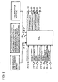
- Fig. 2 is a diagram of an example of a controller 40 to enable stable combustion with oxygen even when the properties of coal (the fuel ratio FR, the carbon content) are varied in the oxyfuel combustion boiler of Fig. 1 .
- the controller 40 is inputted with the total amount of gas recirculated which is measured by the total gas amount meter 36, the supply of the primary oxygen which is measured by the primary oxygen meter 34, the supply of the directly supplied oxygen which is measured by the direct oxygen meter 31, the supply of the secondary oxygen which is measured by the secondary oxygen meter 25, the supply of the OAP oxygen which is measured by the OAP oxygen meter 28, a value of the unburned combustibles which is measured by the unburned combustible measuring means 38 and a value of the NO x density which is measured by the NO x density monitor 37.
- the controller 40 is inputted with the relationship X 1 between the fuel ratio of the coal and the boiler-brought-in oxygen density and/or the relationship X 2 between the fuel ratio of the coal and the rate of the directly supplied oxygen which are measured in advance as above and are shown in Figs. 4(a) and 4(b) .
- the controller 40 is also inputted with the fuel ratio (FR) of the coal currently burned which is measured in advance by the fuel measuring means 39 and a fuel ratio (FR') of new kind of coal to be burned next, which is measured in advance.
- the controller 40 is adapted to output a control signal to regulate the total gas amount regulator 12, a control signal to regulate the OAP oxygen regulator 29, a control signal to regulate the primary oxygen regulator 35, a control signal to regulate the secondary oxygen regulator 26 and a control signal to regulate the direct oxygen regulator 32.
- the unburned combustibles in the ash discharged together with the exhaust gas from the oxyfuel combustion boiler 4 are directly related to boiler efficiency and, therefore, their amount need to be controlled to be lower than a predetermined unburned combustible limit value.
- Some unburned combustible limit values are 5% or less as practical cases.
- the unburned combustibles in the ash may be limited according to the purpose of use of the ash. Therefore, the unburned combustible limit value is set corresponding to circumstances.
- Fig. 3 shows the relationship between the boiler-brought-in oxygen density or the rate of the directly supplied oxygen to the total oxygen amount on one hand and the unburned combustibles on the other hand obtained as a result of combustion tests on coal A (low FR coal) having a low fuel ratio and coal B (high FR coal) having a high fuel rate which are executed in the oxyfuel combustion boiler 4 of Fig. 1 . It is seen in Fig. 3 that the coal B (high FR coal) having the high fuel ratio produces significantly increased amount of unburned combustibles compared to the coal A (low FR coal) having the low fuel ratio.
- Fig. 3 shows the relationship between the boiler-brought-in oxygen density or the rate of the directly supplied oxygen to the total oxygen amount on one hand and the unburned combustibles on the other hand obtained as a result of combustion tests on coal A (low FR coal) having a low fuel ratio and coal B (high FR coal) having a high fuel rate which are
- the controller 40 is inputted in advance with the relationship X 1 between the fuel ratio of the coal and the boiler-brought-in oxygen density and/or the relationship X 2 between the fuel ratio and the rate of the directly supplied oxygen to the total oxygen amount, which is obtained in advance and with which stable combustion is achieved.
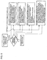
- the controller 40 is adapted to execute automatic control.
- the controller 40 when the fuel ratio (FR') of the coal is high, the controller 40 is caused to regulate the total gas amount regulator 12 to reduce the total amount of gases recirculated to thereby increase the boiler-brought-in oxygen density, or to regulate the direct oxygen regulator 32, the secondary oxygen regulator 26 and the primary oxygen regulator 35 to increase the rate of the directly supplied oxygen, or to execute both of them; when the fuel ratio (FR') of the coal is low, the controller 40 is caused to regulate the total gas amount regulator 12 to increase the total amount of gases recirculated to thereby reduce the boiler-brought-in oxygen density, or to regulate the direct oxygen regulator 32, the secondary oxygen regulator 26 and the primary oxygen regulator 35 to reduce the rate of the directly supplied oxygen, or to execute both of them.
- the total amount of gases recirculated is properly regulated to regulate the boiler-brought-in oxygen density and/or the rate of directly supplied oxygen is properly regulated, so that the amount of the unburned combustibles shown in Fig. 3 can be stably maintained at a predetermined unburned combustible set value S lower than the unburned combustible limit value even when the kind of coal is changed.
- the NO x density of the exhaust gas also needs to be maintained to be lower than a predetermined NO x limit value.
- the NO x limit value is limited, for example, by a regulation on a NO x density or a total emission in a power station and, for example, 180 ppm with which a practical case is present in terms of conversion into a density at a boiler outlet may be employed as a NO x limit value.
- the controller 40 is adapted to regulate the OAP oxygen regulator 29 to control the supply of the OAP supplied oxygen to the OAP recirculation line 17 such that the amount of unburned combustibles measured by the unburned combustible measuring means 38 is maintained at a value lower than the unburned combustible limit value and that the NO x density measured by the NO x density monitor 37 is maintained at a value lower than the NO x limit value.
- controller 40 is further adapted to regulate the primary oxygen regulator 35 to thereby control the supply of the primary oxygen to the primary recirculation line 13 for stable combustion in the burner 6.
- the controller 40 is adapted to execute at least one of the following operations: to regulate the primary oxygen regulator 35 to increase the supply of the primary oxygen to the primary recirculation line 13; to regulate the OAP oxygen regulator 29 to reduce the supply of the OAP supplied oxygen to the OAP recirculation line 17 to thereby increase the burner-brought-in oxygen density; to regulate the total gas amount regulator 12 to reduce the total amount of gases recirculated to thereby increase the boiler-brought-in oxygen density; and to regulate the direct oxygen regulator 32, the secondary oxygen regulator 26 and the primary oxygen regulator 35 to increase the rate of the directly supplied oxygen.
- the burner-brought-in oxygen density represents the oxygen density for the total amount of gases introduced into the burner 6.
- the coal stored in the coal bunker 1 is first measured with respect to its fuel ratio (FR) by the fuel measuring means 39.
- the coal whose fuel ratio (FR) has been measured is charged by the coal feeder 2 into the mill 3 where the coal is pulverized into pulverized coal.
- the primary recirculated exhaust gas which is a portion of the exhaust gas taken out by the forced draft fan 11 (FDF) downstream of the exhaust gas treating devices 9 is introduced into the mill 3 through the primary recirculation line 13.
- the primary recirculated exhaust gas dries the coal charged into the mill 3 and conveys the coal pulverized to the burner 6 of the boiler 4.
- Another portion of the exhaust gas from the forced draft fan 11 is supplied to the wind box 5 of the boiler 4 through the secondary recirculation line 15 as the secondary recirculated exhaust gas.
- the rest of the exhaust gas, which is taken out through the OAP recirculation line 17 branching from the secondary recirculation line 15, is supplied to the OAP 18 of the boiler 4 as the OAP recirculation gas.
- a portion of oxygen produced by the air separation unit 23 is supplied to the secondary recirculation line 15 through the secondary oxygen mixing line 24 as the secondary oxygen, and another portion of the oxygen is supplied to the OAP recirculation line 17 through the OAP oxygen mixing line 27 as the OAP oxygen. Yet another portion of the oxygen is supplied to the primary recirculation line 13 through the primary oxygen mixing line 33 branching from the direct oxygen feed line 30 as the primary oxygen, and the rest of the oxygen is supplied directly to the burner 6 through the direct oxygen feed line 30 as the direct oxygen.
- the pulverized coal supplied by the primary recirculated exhaust gas from the mill 3 to the burner 6 is burned by the primary recirculated gas mixed with oxygen and supplied to the burner 6, the secondary recirculated gas mixed with oxygen and supplied to the wind box 5, the OAP recirculation gas mixed with oxygen and supplied to the OAP 18 and the directly supplied oxygen supplied directly to the burner 6.
- the exhaust gas produced by the combustion preheats the primary and secondary recirculated exhaust gases using the air preheater 8 and is treated by the exhaust gas treating devices 9. Thereafter, the exhaust gas is partly led to the forced draft fan 11 for recirculation as recirculated exhaust gas and to a capture device 20 which captures CO 2 etc.
- the rest of the exhaust gas is induced by the induced draft fan (IDF) and is discharged through a stack 22 to the atmosphere.
- IDF induced draft fan
- the supply of the oxygen produced by the air separation unit 23 is adjusted in accordance with to the supply of the coal (pulverized coal) and, in addition, each of the primary recirculated exhaust gas necessary for conveying the pulverized coal, the secondary recirculated exhaust gas supplied to the wind box 5 and the OAP recirculation exhaust gas supplied to the OAP 18 is regulated and the total amount of gases which is a sum of the amounts of these recirculated exhaust gases is regulated by the total gas amount regulator 12, so that stable combustion is executed in the oxyfuel combustion boiler 4.
- the boiler-brought-in oxygen density is obtained by calculation on the basis of the amount of oxygen supplied from the air separation unit 23 to the boiler 4, and a rate of the directly supplied oxygen to the total oxygen amount is determined.
- the fuel ratio of the new kind of coal (FR') measured in advance by the fuel measuring means 39 is inputted into the controller 40.
- the controller 40 automatically executes one or both of the control of regulating the total gas regulator 12 to regulate the total amount of gases recirculated and the control of regulating the direct oxygen regulator 32, the secondary oxygen regulator 26 and the primary oxygen regulator 35 to regulate the rate of the directly supplied oxygen, on the basis of the relationship X 1 , X 2 shown in Fig. 4 between the fuel ratio (FR) and the boiler-brought-in oxygen density and/or between the fuel ratio (FR) and the rate of the directly supplied oxygen, such that the boiler-brought-in oxygen density and/or the rate of the directly supplied oxygen is obtained which accords with the fuel ratio (FR').
- the total amount of gases recirculated may be properly regulated to regulate the boiler-brought-in oxygen density and/or the rate of the directly supplied oxygen may be properly regulated to regulate the supply of the directly supplied oxygen, so that the amount of the unburned combustibles may be stably maintained at a predetermined unburned combustible set value S lower than the unburned combustible limit value even when the kind of coal to be supplied to the boiler 4 is changed.
- the controller 40 controls the supply of the OAP supplied oxygen supplied to the OAP recirculation line 17 by regulating the OAP oxygen regulator 29 such that the amount of the unburned combustibles measured by the unburned combustible measuring means 38 is maintained to be lower than the unburned combustibles limit value and the NO x density measured by the NO x density monitor 37 is maintained to be lower than the NO x limit value.
- control is automatically executed such that the amount of the unburned combustibles is maintained to be lower than the unburned combustible limit value and the NO x density is maintained to be lower than the NO x limit value.
- the controller 40 may effectively control the shape of the flames of the burner 6 by regulating the supply ratio of the supply of the secondary oxygen to the secondary recirculation line 15 regulated by regulating the secondary oxygen regulator 26 and the supply of the directly supplied oxygen supplied directly to the burner 6 regulated by regulating the direct oxygen regulator 32.
- the controller 40 executes at least one of: an operation of regulating the primary oxygen regulator 35 to increase the supply of the primary oxygen supplied to the primary recirculation line 13; an operation of regulating the OAP oxygen regulator 29 to reduce the supply of the OAP supplied oxygen supplied to the OAP recirculation line 17, thereby increasing the burner-brought-in oxygen density; an operation of regulating the total gas amount regulator 12 to reduce the total amount of gases recirculated, thereby increasing the boiler-brought-in oxygen density; and an operation of regulating the direct oxygen regulator 32, the secondary oxygen regulator 26 and the primary oxygen regulator 35 to reduce the supply of the secondary oxygen, thereby increasing the supply of the direct oxygen.
Landscapes
- Engineering & Computer Science (AREA)
- Chemical & Material Sciences (AREA)
- Combustion & Propulsion (AREA)
- Mechanical Engineering (AREA)
- General Engineering & Computer Science (AREA)
- Physics & Mathematics (AREA)
- Thermal Sciences (AREA)
Priority Applications (1)
| Application Number | Priority Date | Filing Date | Title |
|---|---|---|---|
| PL08720360T PL2267367T3 (pl) | 2008-03-06 | 2008-03-06 | Sposób i urządzenie do kontrolowania dostarczania tlenu w kotle do spalania tlenowo-paliwowego |
Applications Claiming Priority (1)
| Application Number | Priority Date | Filing Date | Title |
|---|---|---|---|
| PCT/JP2008/000474 WO2009110036A1 (fr) | 2008-03-06 | 2008-03-06 | Procédé de contrôle d'alimentation en oxygène dans un brûleur à combustion d'oxygène et son appareil |
Publications (3)
| Publication Number | Publication Date |
|---|---|
| EP2267367A1 true EP2267367A1 (fr) | 2010-12-29 |
| EP2267367A4 EP2267367A4 (fr) | 2012-06-13 |
| EP2267367B1 EP2267367B1 (fr) | 2014-11-26 |
Family
ID=41055618
Family Applications (1)
| Application Number | Title | Priority Date | Filing Date |
|---|---|---|---|
| EP08720360.0A Active EP2267367B1 (fr) | 2008-03-06 | 2008-03-06 | Procede et appareil de controle d'alimentation en oxygene dans une chaudiere a oxycombustion |
Country Status (8)
| Country | Link |
|---|---|
| US (1) | US9429315B2 (fr) |
| EP (1) | EP2267367B1 (fr) |
| JP (1) | JP5138028B2 (fr) |
| CN (1) | CN102016418B (fr) |
| AU (1) | AU2008352212C1 (fr) |
| ES (1) | ES2527501T3 (fr) |
| PL (1) | PL2267367T3 (fr) |
| WO (1) | WO2009110036A1 (fr) |
Cited By (1)
| Publication number | Priority date | Publication date | Assignee | Title |
|---|---|---|---|---|
| RU2460939C1 (ru) * | 2011-06-15 | 2012-09-10 | Учреждение Российской академии наук Институт вычислительного моделирования Сибирского отделения Российской академии наук (ИВМ СО РАН) | Способ работы тангенциальной топки |
Families Citing this family (20)
| Publication number | Priority date | Publication date | Assignee | Title |
|---|---|---|---|---|
| US8453585B2 (en) * | 2008-04-14 | 2013-06-04 | Babcock & Wilcox Power Generation Group, Inc. | Oxy-combustion coal fired boiler and method of transitioning between air and oxygen firing |
| JP4896194B2 (ja) * | 2009-09-30 | 2012-03-14 | 株式会社日立製作所 | 酸素燃焼ボイラプラント |
| EP2336637A1 (fr) * | 2009-12-14 | 2011-06-22 | ABB Research Ltd. | Système et procédé associé de surveillance et de contrôle d'une centrale électrique |
| DE102010007094B4 (de) * | 2010-02-06 | 2015-05-28 | Khd Humboldt Wedag Gmbh | Verfahren zur Reaktivitätssteigerung von feuchtem Brennstoff |
| JP5377371B2 (ja) * | 2010-03-12 | 2013-12-25 | 株式会社日立製作所 | 酸素燃焼型石炭火力発電システム |
| US10718511B2 (en) | 2010-07-02 | 2020-07-21 | Harry R. Taplin, JR. | System for combustion of fuel to provide high efficiency, low pollution energy |
| US8852300B2 (en) * | 2010-07-02 | 2014-10-07 | Harry R. Taplin, JR. | Lithium conditioned engine with reduced carbon oxide emissions |
| CN102374525A (zh) * | 2010-08-12 | 2012-03-14 | 上海尚实能源科技有限公司 | 补氧型烟气循环燃烧装置 |
| JP2012088016A (ja) * | 2010-10-22 | 2012-05-10 | Babcock Hitachi Kk | 酸素燃焼式ボイラ及びその運転方法 |
| US20120244479A1 (en) * | 2011-03-22 | 2012-09-27 | General Electric Company | Combustion System Using Recycled Flue Gas to Boost Overfire Air |
| JP5789146B2 (ja) * | 2011-07-13 | 2015-10-07 | 株式会社神戸製鋼所 | 微粉炭焚きボイラ設備の運転方法および微粉炭焚きボイラ設備 |
| CN102563687B (zh) * | 2012-03-07 | 2014-05-14 | 上海锅炉厂有限公司 | 富氧燃烧系统 |
| CN102588997B (zh) * | 2012-03-07 | 2014-07-09 | 上海锅炉厂有限公司 | 富氧燃烧系统 |
| KR101405015B1 (ko) | 2012-09-11 | 2014-06-10 | 한국전력공사 | 연소설비의 공기공급장치 및 공기공급방법 |
| US20150083032A1 (en) * | 2013-09-20 | 2015-03-26 | Massachusetts Institute Of Technology | Combustion System |
| CN105042630B (zh) * | 2015-07-27 | 2017-10-17 | 中国神华能源股份有限公司 | 富氧燃烧系统供氧控制装置和方法 |
| CN105180205B (zh) * | 2015-08-14 | 2017-08-25 | 中国神华能源股份有限公司 | 富氧燃烧烟气循环系统控制方法 |
| JP6987659B2 (ja) * | 2018-01-31 | 2022-01-05 | 三菱パワー株式会社 | ボイラの制御装置及び制御方法 |
| CN110762549A (zh) * | 2019-10-30 | 2020-02-07 | 徐州宝美工程机械有限公司 | 一种冶金用煤炭高效燃烧破碎添加系统 |
| US20220049848A1 (en) * | 2020-08-12 | 2022-02-17 | Air Products And Chemicals, Inc. | System and Method for Combusting High-Moisture Fuel to Generate Steam |
Citations (5)
| Publication number | Priority date | Publication date | Assignee | Title |
|---|---|---|---|---|
| US3043525A (en) * | 1960-03-10 | 1962-07-10 | Bailey Meter Co | Pulverizer control |
| JPH06101809A (ja) * | 1992-09-21 | 1994-04-12 | Ishikawajima Harima Heavy Ind Co Ltd | ボイラ設備 |
| EP0773408A1 (fr) * | 1995-11-07 | 1997-05-14 | Hitachi, Ltd. | Dispositif de commande de l'évaluation de l'état de la chaudière intérieure d'une chaudière à charbon pulvérisé |
| US20070034704A1 (en) * | 2005-08-12 | 2007-02-15 | Tailai Hu | Oxygen-enriched air assisting system for improving the efficiency of cogeneration system |
| JP2007147162A (ja) * | 2005-11-28 | 2007-06-14 | Electric Power Dev Co Ltd | 酸素燃焼ボイラの燃焼制御方法及び装置 |
Family Cites Families (23)
| Publication number | Priority date | Publication date | Assignee | Title |
|---|---|---|---|---|
| JPS5924104A (ja) | 1982-07-29 | 1984-02-07 | Babcock Hitachi Kk | 微粉炭低窒素酸化物燃焼法 |
| JPS5928486A (ja) | 1982-08-10 | 1984-02-15 | Ajinomoto Co Inc | S−カルボキシメチル−l−システインの製造法 |
| JPS5942452A (ja) | 1982-09-02 | 1984-03-09 | Sekisui Chem Co Ltd | 免疫化学的測定試薬用担体の製造方法 |
| JPS5942452U (ja) * | 1982-09-11 | 1984-03-19 | バブコツク日立株式会社 | 脱硝燃焼装置 |
| JP2912970B2 (ja) * | 1990-01-26 | 1999-06-28 | バブコツク日立株式会社 | 灰中未燃分測定装置 |
| JPH04244504A (ja) | 1991-01-30 | 1992-09-01 | Central Res Inst Of Electric Power Ind | 二酸化炭素回収型石炭火力発電システム |
| JP3068888B2 (ja) | 1991-05-28 | 2000-07-24 | 株式会社日立製作所 | 燃焼装置及びその運転方法 |
| JP3053914B2 (ja) * | 1991-07-16 | 2000-06-19 | バブコック日立株式会社 | Co2回収型ボイラ |
| JP3038073B2 (ja) | 1991-12-20 | 2000-05-08 | 電源開発株式会社 | 流動床ボイラのn▲2▼o削減方法 |
| JP3181649B2 (ja) | 1991-12-20 | 2001-07-03 | 電源開発株式会社 | ボイラの二酸化炭素回収装置 |
| US5280756A (en) * | 1992-02-04 | 1994-01-25 | Stone & Webster Engineering Corp. | NOx Emissions advisor and automation system |
| JPH0694212A (ja) | 1992-09-10 | 1994-04-05 | Mitsubishi Heavy Ind Ltd | 化石燃料燃焼ボイラ |
| JP3338555B2 (ja) | 1994-05-24 | 2002-10-28 | 電源開発株式会社 | 二酸化炭素回収型排ガス再循環ボイラ設備の燃焼バーナ |
| CA2162244C (fr) * | 1994-11-14 | 1999-04-27 | Hideaki Oota | Bruleur a combustion de charbon pulverise |
| JP3577961B2 (ja) * | 1998-02-27 | 2004-10-20 | トヨタ自動車株式会社 | 燃焼式ヒータを有する内燃機関 |
| AUPP573098A0 (en) * | 1998-09-04 | 1998-10-01 | Generation Technology Research Pty Ltd | Apparatus and method for analyzing material |
| JP2001235103A (ja) | 2000-02-21 | 2001-08-31 | Babcock Hitachi Kk | 酸素燃焼ボイラとその運転方法 |
| JP4161515B2 (ja) | 2000-05-30 | 2008-10-08 | 株式会社Ihi | 酸素燃焼ボイラ設備の排ガス酸素濃度制御方法及び装置 |
| US6935251B2 (en) | 2002-02-15 | 2005-08-30 | American Air Liquide, Inc. | Steam-generating combustion system and method for emission control using oxygen enhancement |
| JP3790504B2 (ja) | 2002-08-09 | 2006-06-28 | 三菱重工業株式会社 | 微粉炭燃焼システム |
| JP2007147161A (ja) | 2005-11-28 | 2007-06-14 | Electric Power Dev Co Ltd | 燃焼装置の排ガス処分方法及び装置 |
| US7756591B2 (en) * | 2006-04-25 | 2010-07-13 | Pegasus Technologies, Inc. | System for optimizing oxygen in a boiler |
| US9651253B2 (en) * | 2007-05-15 | 2017-05-16 | Doosan Power Systems Americas, Llc | Combustion apparatus |
-
2008
- 2008-03-06 ES ES08720360.0T patent/ES2527501T3/es active Active
- 2008-03-06 WO PCT/JP2008/000474 patent/WO2009110036A1/fr active Application Filing
- 2008-03-06 AU AU2008352212A patent/AU2008352212C1/en active Active
- 2008-03-06 PL PL08720360T patent/PL2267367T3/pl unknown
- 2008-03-06 CN CN200880129049XA patent/CN102016418B/zh active Active
- 2008-03-06 US US12/920,602 patent/US9429315B2/en active Active
- 2008-03-06 EP EP08720360.0A patent/EP2267367B1/fr active Active
- 2008-03-06 JP JP2010501688A patent/JP5138028B2/ja active Active
Patent Citations (5)
| Publication number | Priority date | Publication date | Assignee | Title |
|---|---|---|---|---|
| US3043525A (en) * | 1960-03-10 | 1962-07-10 | Bailey Meter Co | Pulverizer control |
| JPH06101809A (ja) * | 1992-09-21 | 1994-04-12 | Ishikawajima Harima Heavy Ind Co Ltd | ボイラ設備 |
| EP0773408A1 (fr) * | 1995-11-07 | 1997-05-14 | Hitachi, Ltd. | Dispositif de commande de l'évaluation de l'état de la chaudière intérieure d'une chaudière à charbon pulvérisé |
| US20070034704A1 (en) * | 2005-08-12 | 2007-02-15 | Tailai Hu | Oxygen-enriched air assisting system for improving the efficiency of cogeneration system |
| JP2007147162A (ja) * | 2005-11-28 | 2007-06-14 | Electric Power Dev Co Ltd | 酸素燃焼ボイラの燃焼制御方法及び装置 |
Non-Patent Citations (3)
| Title |
|---|
| DUNKER R: "BRENNERTECHNIK MIT NEUEM FREIHEITSGRAD", BWK BRENNSTOFF WARME KRAFT, SPRINGER VDI VERLAG, DUSSELDORF, DE, vol. 59, no. 3, 1 January 2007 (2007-01-01), pages 51-54, XP001504848, ISSN: 1618-193X * |
| Kather, Hermsdorf, Klostermann: "Der kohlebefeuerte Oxyfuel-Process", , 30 April 2007 (2007-04-30), XP002675101, Retrieved from the Internet: URL:http://www.adecos.de/download/publikationen/070400_vgb-powertech_tuhh.pdf [retrieved on 2012-04-27] * |
| See also references of WO2009110036A1 * |
Cited By (1)
| Publication number | Priority date | Publication date | Assignee | Title |
|---|---|---|---|---|
| RU2460939C1 (ru) * | 2011-06-15 | 2012-09-10 | Учреждение Российской академии наук Институт вычислительного моделирования Сибирского отделения Российской академии наук (ИВМ СО РАН) | Способ работы тангенциальной топки |
Also Published As
| Publication number | Publication date |
|---|---|
| AU2008352212A1 (en) | 2009-09-11 |
| US9429315B2 (en) | 2016-08-30 |
| US20110083594A1 (en) | 2011-04-14 |
| CN102016418A (zh) | 2011-04-13 |
| WO2009110036A1 (fr) | 2009-09-11 |
| PL2267367T3 (pl) | 2015-05-29 |
| ES2527501T3 (es) | 2015-01-26 |
| CN102016418B (zh) | 2013-02-06 |
| AU2008352212B2 (en) | 2012-08-30 |
| JP5138028B2 (ja) | 2013-02-06 |
| JPWO2009110036A1 (ja) | 2011-07-14 |
| EP2267367A4 (fr) | 2012-06-13 |
| AU2008352212C1 (en) | 2012-11-29 |
| EP2267367B1 (fr) | 2014-11-26 |
Similar Documents
| Publication | Publication Date | Title |
|---|---|---|
| US9429315B2 (en) | Method and apparatus of controlling oxygen supply in oxyfuel combustion boiler | |
| US8550017B2 (en) | Method and apparatus of controlling exhaust gas in oxyfuel combustion boiler | |
| US8601960B2 (en) | Method and apparatus of controlling exhaust gas in oxyfuel combustion boiler | |
| US8584604B2 (en) | Method and apparatus for controlling combustion in oxygen fired boiler | |
| AU2008352210B2 (en) | Method and apparatus of controlling flow rate of primary recirculating exhaust gas in oxyfuel combustion boiler | |
| AU2008352211B2 (en) | Method and apparatus of controlling combustion in oxyfuel combustion boiler | |
| US9429319B2 (en) | Boiler combustion system and operation method therefor |
Legal Events
| Date | Code | Title | Description |
|---|---|---|---|
| PUAI | Public reference made under article 153(3) epc to a published international application that has entered the european phase |
Free format text: ORIGINAL CODE: 0009012 |
|
| 17P | Request for examination filed |
Effective date: 20101004 |
|
| AK | Designated contracting states |
Kind code of ref document: A1 Designated state(s): AT BE BG CH CY CZ DE DK EE ES FI FR GB GR HR HU IE IS IT LI LT LU LV MC MT NL NO PL PT RO SE SI SK TR |
|
| AX | Request for extension of the european patent |
Extension state: AL BA MK RS |
|
| DAX | Request for extension of the european patent (deleted) | ||
| RIC1 | Information provided on ipc code assigned before grant |
Ipc: F23K 3/02 20060101ALI20120503BHEP Ipc: F23C 9/00 20060101ALI20120503BHEP Ipc: F23N 5/00 20060101ALI20120503BHEP Ipc: F22B 35/00 20060101ALI20120503BHEP Ipc: F23L 9/02 20060101ALI20120503BHEP Ipc: F23C 99/00 20060101AFI20120503BHEP Ipc: F23L 7/00 20060101ALI20120503BHEP |
|
| A4 | Supplementary search report drawn up and despatched |
Effective date: 20120515 |
|
| 17Q | First examination report despatched |
Effective date: 20130207 |
|
| GRAP | Despatch of communication of intention to grant a patent |
Free format text: ORIGINAL CODE: EPIDOSNIGR1 |
|
| INTG | Intention to grant announced |
Effective date: 20140313 |
|
| GRAS | Grant fee paid |
Free format text: ORIGINAL CODE: EPIDOSNIGR3 |
|
| GRAP | Despatch of communication of intention to grant a patent |
Free format text: ORIGINAL CODE: EPIDOSNIGR1 |
|
| INTG | Intention to grant announced |
Effective date: 20140917 |
|
| GRAA | (expected) grant |
Free format text: ORIGINAL CODE: 0009210 |
|
| AK | Designated contracting states |
Kind code of ref document: B1 Designated state(s): AT BE BG CH CY CZ DE DK EE ES FI FR GB GR HR HU IE IS IT LI LT LU LV MC MT NL NO PL PT RO SE SI SK TR |
|
| REG | Reference to a national code |
Ref country code: GB Ref legal event code: FG4D |
|
| REG | Reference to a national code |
Ref country code: CH Ref legal event code: EP |
|
| REG | Reference to a national code |
Ref country code: AT Ref legal event code: REF Ref document number: 698421 Country of ref document: AT Kind code of ref document: T Effective date: 20141215 |
|
| REG | Reference to a national code |
Ref country code: IE Ref legal event code: FG4D |
|
| REG | Reference to a national code |
Ref country code: DE Ref legal event code: R096 Ref document number: 602008035568 Country of ref document: DE Effective date: 20150108 |
|
| REG | Reference to a national code |
Ref country code: ES Ref legal event code: FG2A Ref document number: 2527501 Country of ref document: ES Kind code of ref document: T3 Effective date: 20150126 |
|
| REG | Reference to a national code |
Ref country code: NL Ref legal event code: VDEP Effective date: 20141126 |
|
| REG | Reference to a national code |
Ref country code: AT Ref legal event code: MK05 Ref document number: 698421 Country of ref document: AT Kind code of ref document: T Effective date: 20141126 |
|
| REG | Reference to a national code |
Ref country code: LT Ref legal event code: MG4D |
|
| PG25 | Lapsed in a contracting state [announced via postgrant information from national office to epo] |
Ref country code: NO Free format text: LAPSE BECAUSE OF FAILURE TO SUBMIT A TRANSLATION OF THE DESCRIPTION OR TO PAY THE FEE WITHIN THE PRESCRIBED TIME-LIMIT Effective date: 20150226 Ref country code: FI Free format text: LAPSE BECAUSE OF FAILURE TO SUBMIT A TRANSLATION OF THE DESCRIPTION OR TO PAY THE FEE WITHIN THE PRESCRIBED TIME-LIMIT Effective date: 20141126 Ref country code: IS Free format text: LAPSE BECAUSE OF FAILURE TO SUBMIT A TRANSLATION OF THE DESCRIPTION OR TO PAY THE FEE WITHIN THE PRESCRIBED TIME-LIMIT Effective date: 20150326 Ref country code: NL Free format text: LAPSE BECAUSE OF FAILURE TO SUBMIT A TRANSLATION OF THE DESCRIPTION OR TO PAY THE FEE WITHIN THE PRESCRIBED TIME-LIMIT Effective date: 20141126 Ref country code: PT Free format text: LAPSE BECAUSE OF FAILURE TO SUBMIT A TRANSLATION OF THE DESCRIPTION OR TO PAY THE FEE WITHIN THE PRESCRIBED TIME-LIMIT Effective date: 20150326 Ref country code: LT Free format text: LAPSE BECAUSE OF FAILURE TO SUBMIT A TRANSLATION OF THE DESCRIPTION OR TO PAY THE FEE WITHIN THE PRESCRIBED TIME-LIMIT Effective date: 20141126 |
|
| PG25 | Lapsed in a contracting state [announced via postgrant information from national office to epo] |
Ref country code: SE Free format text: LAPSE BECAUSE OF FAILURE TO SUBMIT A TRANSLATION OF THE DESCRIPTION OR TO PAY THE FEE WITHIN THE PRESCRIBED TIME-LIMIT Effective date: 20141126 Ref country code: HR Free format text: LAPSE BECAUSE OF FAILURE TO SUBMIT A TRANSLATION OF THE DESCRIPTION OR TO PAY THE FEE WITHIN THE PRESCRIBED TIME-LIMIT Effective date: 20141126 Ref country code: AT Free format text: LAPSE BECAUSE OF FAILURE TO SUBMIT A TRANSLATION OF THE DESCRIPTION OR TO PAY THE FEE WITHIN THE PRESCRIBED TIME-LIMIT Effective date: 20141126 Ref country code: CY Free format text: LAPSE BECAUSE OF FAILURE TO SUBMIT A TRANSLATION OF THE DESCRIPTION OR TO PAY THE FEE WITHIN THE PRESCRIBED TIME-LIMIT Effective date: 20141126 Ref country code: LV Free format text: LAPSE BECAUSE OF FAILURE TO SUBMIT A TRANSLATION OF THE DESCRIPTION OR TO PAY THE FEE WITHIN THE PRESCRIBED TIME-LIMIT Effective date: 20141126 Ref country code: GR Free format text: LAPSE BECAUSE OF FAILURE TO SUBMIT A TRANSLATION OF THE DESCRIPTION OR TO PAY THE FEE WITHIN THE PRESCRIBED TIME-LIMIT Effective date: 20150227 |
|
| REG | Reference to a national code |
Ref country code: PL Ref legal event code: T3 |
|
| PG25 | Lapsed in a contracting state [announced via postgrant information from national office to epo] |
Ref country code: SK Free format text: LAPSE BECAUSE OF FAILURE TO SUBMIT A TRANSLATION OF THE DESCRIPTION OR TO PAY THE FEE WITHIN THE PRESCRIBED TIME-LIMIT Effective date: 20141126 Ref country code: CZ Free format text: LAPSE BECAUSE OF FAILURE TO SUBMIT A TRANSLATION OF THE DESCRIPTION OR TO PAY THE FEE WITHIN THE PRESCRIBED TIME-LIMIT Effective date: 20141126 Ref country code: DK Free format text: LAPSE BECAUSE OF FAILURE TO SUBMIT A TRANSLATION OF THE DESCRIPTION OR TO PAY THE FEE WITHIN THE PRESCRIBED TIME-LIMIT Effective date: 20141126 Ref country code: EE Free format text: LAPSE BECAUSE OF FAILURE TO SUBMIT A TRANSLATION OF THE DESCRIPTION OR TO PAY THE FEE WITHIN THE PRESCRIBED TIME-LIMIT Effective date: 20141126 Ref country code: RO Free format text: LAPSE BECAUSE OF FAILURE TO SUBMIT A TRANSLATION OF THE DESCRIPTION OR TO PAY THE FEE WITHIN THE PRESCRIBED TIME-LIMIT Effective date: 20141126 |
|
| REG | Reference to a national code |
Ref country code: DE Ref legal event code: R097 Ref document number: 602008035568 Country of ref document: DE |
|
| PLBE | No opposition filed within time limit |
Free format text: ORIGINAL CODE: 0009261 |
|
| STAA | Information on the status of an ep patent application or granted ep patent |
Free format text: STATUS: NO OPPOSITION FILED WITHIN TIME LIMIT |
|
| PG25 | Lapsed in a contracting state [announced via postgrant information from national office to epo] |
Ref country code: LU Free format text: LAPSE BECAUSE OF FAILURE TO SUBMIT A TRANSLATION OF THE DESCRIPTION OR TO PAY THE FEE WITHIN THE PRESCRIBED TIME-LIMIT Effective date: 20150306 Ref country code: MC Free format text: LAPSE BECAUSE OF FAILURE TO SUBMIT A TRANSLATION OF THE DESCRIPTION OR TO PAY THE FEE WITHIN THE PRESCRIBED TIME-LIMIT Effective date: 20141126 |
|
| REG | Reference to a national code |
Ref country code: CH Ref legal event code: PL |
|
| 26N | No opposition filed |
Effective date: 20150827 |
|
| REG | Reference to a national code |
Ref country code: IE Ref legal event code: MM4A |
|
| PG25 | Lapsed in a contracting state [announced via postgrant information from national office to epo] |
Ref country code: CH Free format text: LAPSE BECAUSE OF NON-PAYMENT OF DUE FEES Effective date: 20150331 Ref country code: LI Free format text: LAPSE BECAUSE OF NON-PAYMENT OF DUE FEES Effective date: 20150331 Ref country code: IE Free format text: LAPSE BECAUSE OF NON-PAYMENT OF DUE FEES Effective date: 20150306 |
|
| REG | Reference to a national code |
Ref country code: FR Ref legal event code: PLFP Year of fee payment: 9 |
|
| PG25 | Lapsed in a contracting state [announced via postgrant information from national office to epo] |
Ref country code: SI Free format text: LAPSE BECAUSE OF FAILURE TO SUBMIT A TRANSLATION OF THE DESCRIPTION OR TO PAY THE FEE WITHIN THE PRESCRIBED TIME-LIMIT Effective date: 20141126 |
|
| PG25 | Lapsed in a contracting state [announced via postgrant information from national office to epo] |
Ref country code: MT Free format text: LAPSE BECAUSE OF FAILURE TO SUBMIT A TRANSLATION OF THE DESCRIPTION OR TO PAY THE FEE WITHIN THE PRESCRIBED TIME-LIMIT Effective date: 20141126 |
|
| REG | Reference to a national code |
Ref country code: FR Ref legal event code: PLFP Year of fee payment: 10 |
|
| PG25 | Lapsed in a contracting state [announced via postgrant information from national office to epo] |
Ref country code: BG Free format text: LAPSE BECAUSE OF FAILURE TO SUBMIT A TRANSLATION OF THE DESCRIPTION OR TO PAY THE FEE WITHIN THE PRESCRIBED TIME-LIMIT Effective date: 20141126 Ref country code: HU Free format text: LAPSE BECAUSE OF FAILURE TO SUBMIT A TRANSLATION OF THE DESCRIPTION OR TO PAY THE FEE WITHIN THE PRESCRIBED TIME-LIMIT; INVALID AB INITIO Effective date: 20080306 |
|
| PG25 | Lapsed in a contracting state [announced via postgrant information from national office to epo] |
Ref country code: TR Free format text: LAPSE BECAUSE OF FAILURE TO SUBMIT A TRANSLATION OF THE DESCRIPTION OR TO PAY THE FEE WITHIN THE PRESCRIBED TIME-LIMIT Effective date: 20141126 |
|
| PG25 | Lapsed in a contracting state [announced via postgrant information from national office to epo] |
Ref country code: BE Free format text: LAPSE BECAUSE OF FAILURE TO SUBMIT A TRANSLATION OF THE DESCRIPTION OR TO PAY THE FEE WITHIN THE PRESCRIBED TIME-LIMIT Effective date: 20141126 |
|
| REG | Reference to a national code |
Ref country code: FR Ref legal event code: PLFP Year of fee payment: 11 |
|
| PGFP | Annual fee paid to national office [announced via postgrant information from national office to epo] |
Ref country code: FR Payment date: 20230208 Year of fee payment: 16 |
|
| PGFP | Annual fee paid to national office [announced via postgrant information from national office to epo] |
Ref country code: PL Payment date: 20230214 Year of fee payment: 16 Ref country code: IT Payment date: 20230213 Year of fee payment: 16 |
|
| PGFP | Annual fee paid to national office [announced via postgrant information from national office to epo] |
Ref country code: ES Payment date: 20230404 Year of fee payment: 16 |
|
| PGFP | Annual fee paid to national office [announced via postgrant information from national office to epo] |
Ref country code: DE Payment date: 20240130 Year of fee payment: 17 Ref country code: GB Payment date: 20240201 Year of fee payment: 17 |