EP2265689B1 - Neue materialien für organische elektrolumineszenzvorrichtungen - Google Patents
Neue materialien für organische elektrolumineszenzvorrichtungen Download PDFInfo
- Publication number
- EP2265689B1 EP2265689B1 EP09732312.5A EP09732312A EP2265689B1 EP 2265689 B1 EP2265689 B1 EP 2265689B1 EP 09732312 A EP09732312 A EP 09732312A EP 2265689 B1 EP2265689 B1 EP 2265689B1
- Authority
- EP
- European Patent Office
- Prior art keywords
- organic
- compounds
- layers
- atoms
- compound
- Prior art date
- Legal status (The legal status is an assumption and is not a legal conclusion. Google has not performed a legal analysis and makes no representation as to the accuracy of the status listed.)
- Active
Links
- 0 CC(*)C1C2=C(*)c3ccc(C(*4*)(C(C)=C)c5c(cccc6)c6ccc5C)c4c3C(*)(*)C(*)=C2C1(*)C(*)=C Chemical compound CC(*)C1C2=C(*)c3ccc(C(*4*)(C(C)=C)c5c(cccc6)c6ccc5C)c4c3C(*)(*)C(*)=C2C1(*)C(*)=C 0.000 description 14
- NVZWEEGUWXZOKI-UHFFFAOYSA-N Cc1c(C=C)cccc1 Chemical compound Cc1c(C=C)cccc1 NVZWEEGUWXZOKI-UHFFFAOYSA-N 0.000 description 2
- SZYWOMWWGLPFDD-UHFFFAOYSA-N C(C1)C=CC=C1c1c(cc(c2c3)-c4ccccc4C2(c(cc2)ccc2-c2nc(cccc4)c4[n]2-c2ccccc2)c(cc2)ccc2-c2nc(cccc4)c4[n]2-c2ccccc2)c3c(-c2ccccc2)c2ccccc12 Chemical compound C(C1)C=CC=C1c1c(cc(c2c3)-c4ccccc4C2(c(cc2)ccc2-c2nc(cccc4)c4[n]2-c2ccccc2)c(cc2)ccc2-c2nc(cccc4)c4[n]2-c2ccccc2)c3c(-c2ccccc2)c2ccccc12 SZYWOMWWGLPFDD-UHFFFAOYSA-N 0.000 description 1
- SPAXAGFSFGMSFU-UHFFFAOYSA-N c(cc1)ccc1-c(cc1)ccc1-c1c(ccc2c3[o]c4c2cccc4)c3c(-c(cc2)ccc2-c2ccccc2)c(cc2)c1c1c2c2ccccc2[o]1 Chemical compound c(cc1)ccc1-c(cc1)ccc1-c1c(ccc2c3[o]c4c2cccc4)c3c(-c(cc2)ccc2-c2ccccc2)c(cc2)c1c1c2c2ccccc2[o]1 SPAXAGFSFGMSFU-UHFFFAOYSA-N 0.000 description 1
Images
Classifications
-
- C—CHEMISTRY; METALLURGY
- C09—DYES; PAINTS; POLISHES; NATURAL RESINS; ADHESIVES; COMPOSITIONS NOT OTHERWISE PROVIDED FOR; APPLICATIONS OF MATERIALS NOT OTHERWISE PROVIDED FOR
- C09K—MATERIALS FOR MISCELLANEOUS APPLICATIONS, NOT PROVIDED FOR ELSEWHERE
- C09K11/00—Luminescent, e.g. electroluminescent, chemiluminescent materials
- C09K11/06—Luminescent, e.g. electroluminescent, chemiluminescent materials containing organic luminescent materials
-
- C—CHEMISTRY; METALLURGY
- C07—ORGANIC CHEMISTRY
- C07C—ACYCLIC OR CARBOCYCLIC COMPOUNDS
- C07C13/00—Cyclic hydrocarbons containing rings other than, or in addition to, six-membered aromatic rings
- C07C13/28—Polycyclic hydrocarbons or acyclic hydrocarbon derivatives thereof
- C07C13/32—Polycyclic hydrocarbons or acyclic hydrocarbon derivatives thereof with condensed rings
- C07C13/62—Polycyclic hydrocarbons or acyclic hydrocarbon derivatives thereof with condensed rings with more than three condensed rings
-
- C—CHEMISTRY; METALLURGY
- C07—ORGANIC CHEMISTRY
- C07D—HETEROCYCLIC COMPOUNDS
- C07D213/00—Heterocyclic compounds containing six-membered rings, not condensed with other rings, with one nitrogen atom as the only ring hetero atom and three or more double bonds between ring members or between ring members and non-ring members
- C07D213/02—Heterocyclic compounds containing six-membered rings, not condensed with other rings, with one nitrogen atom as the only ring hetero atom and three or more double bonds between ring members or between ring members and non-ring members having three double bonds between ring members or between ring members and non-ring members
- C07D213/04—Heterocyclic compounds containing six-membered rings, not condensed with other rings, with one nitrogen atom as the only ring hetero atom and three or more double bonds between ring members or between ring members and non-ring members having three double bonds between ring members or between ring members and non-ring members having no bond between the ring nitrogen atom and a non-ring member or having only hydrogen or carbon atoms directly attached to the ring nitrogen atom
- C07D213/24—Heterocyclic compounds containing six-membered rings, not condensed with other rings, with one nitrogen atom as the only ring hetero atom and three or more double bonds between ring members or between ring members and non-ring members having three double bonds between ring members or between ring members and non-ring members having no bond between the ring nitrogen atom and a non-ring member or having only hydrogen or carbon atoms directly attached to the ring nitrogen atom with substituted hydrocarbon radicals attached to ring carbon atoms
- C07D213/36—Radicals substituted by singly-bound nitrogen atoms
- C07D213/38—Radicals substituted by singly-bound nitrogen atoms having only hydrogen or hydrocarbon radicals attached to the substituent nitrogen atom
-
- C—CHEMISTRY; METALLURGY
- C07—ORGANIC CHEMISTRY
- C07D—HETEROCYCLIC COMPOUNDS
- C07D235/00—Heterocyclic compounds containing 1,3-diazole or hydrogenated 1,3-diazole rings, condensed with other rings
- C07D235/02—Heterocyclic compounds containing 1,3-diazole or hydrogenated 1,3-diazole rings, condensed with other rings condensed with carbocyclic rings or ring systems
- C07D235/04—Benzimidazoles; Hydrogenated benzimidazoles
- C07D235/06—Benzimidazoles; Hydrogenated benzimidazoles with only hydrogen atoms, hydrocarbon or substituted hydrocarbon radicals, directly attached in position 2
- C07D235/08—Radicals containing only hydrogen and carbon atoms
-
- C—CHEMISTRY; METALLURGY
- C07—ORGANIC CHEMISTRY
- C07D—HETEROCYCLIC COMPOUNDS
- C07D307/00—Heterocyclic compounds containing five-membered rings having one oxygen atom as the only ring hetero atom
- C07D307/77—Heterocyclic compounds containing five-membered rings having one oxygen atom as the only ring hetero atom ortho- or peri-condensed with carbocyclic rings or ring systems
- C07D307/78—Benzo [b] furans; Hydrogenated benzo [b] furans
- C07D307/79—Benzo [b] furans; Hydrogenated benzo [b] furans with only hydrogen atoms, hydrocarbon or substituted hydrocarbon radicals, directly attached to carbon atoms of the hetero ring
- C07D307/80—Radicals substituted by oxygen atoms
-
- C—CHEMISTRY; METALLURGY
- C07—ORGANIC CHEMISTRY
- C07D—HETEROCYCLIC COMPOUNDS
- C07D307/00—Heterocyclic compounds containing five-membered rings having one oxygen atom as the only ring hetero atom
- C07D307/94—Heterocyclic compounds containing five-membered rings having one oxygen atom as the only ring hetero atom spiro-condensed with carbocyclic rings or ring systems, e.g. griseofulvins
-
- C—CHEMISTRY; METALLURGY
- C07—ORGANIC CHEMISTRY
- C07D—HETEROCYCLIC COMPOUNDS
- C07D317/00—Heterocyclic compounds containing five-membered rings having two oxygen atoms as the only ring hetero atoms
- C07D317/08—Heterocyclic compounds containing five-membered rings having two oxygen atoms as the only ring hetero atoms having the hetero atoms in positions 1 and 3
- C07D317/72—Heterocyclic compounds containing five-membered rings having two oxygen atoms as the only ring hetero atoms having the hetero atoms in positions 1 and 3 spiro-condensed with carbocyclic rings
-
- C—CHEMISTRY; METALLURGY
- C07—ORGANIC CHEMISTRY
- C07D—HETEROCYCLIC COMPOUNDS
- C07D333/00—Heterocyclic compounds containing five-membered rings having one sulfur atom as the only ring hetero atom
- C07D333/02—Heterocyclic compounds containing five-membered rings having one sulfur atom as the only ring hetero atom not condensed with other rings
- C07D333/04—Heterocyclic compounds containing five-membered rings having one sulfur atom as the only ring hetero atom not condensed with other rings not substituted on the ring sulphur atom
- C07D333/06—Heterocyclic compounds containing five-membered rings having one sulfur atom as the only ring hetero atom not condensed with other rings not substituted on the ring sulphur atom with only hydrogen atoms, hydrocarbon or substituted hydrocarbon radicals, directly attached to the ring carbon atoms
- C07D333/14—Radicals substituted by singly bound hetero atoms other than halogen
- C07D333/18—Radicals substituted by singly bound hetero atoms other than halogen by sulfur atoms
-
- C—CHEMISTRY; METALLURGY
- C07—ORGANIC CHEMISTRY
- C07D—HETEROCYCLIC COMPOUNDS
- C07D335/00—Heterocyclic compounds containing six-membered rings having one sulfur atom as the only ring hetero atom
- C07D335/04—Heterocyclic compounds containing six-membered rings having one sulfur atom as the only ring hetero atom condensed with carbocyclic rings or ring systems
-
- C—CHEMISTRY; METALLURGY
- C07—ORGANIC CHEMISTRY
- C07D—HETEROCYCLIC COMPOUNDS
- C07D471/00—Heterocyclic compounds containing nitrogen atoms as the only ring hetero atoms in the condensed system, at least one ring being a six-membered ring with one nitrogen atom, not provided for by groups C07D451/00 - C07D463/00
- C07D471/02—Heterocyclic compounds containing nitrogen atoms as the only ring hetero atoms in the condensed system, at least one ring being a six-membered ring with one nitrogen atom, not provided for by groups C07D451/00 - C07D463/00 in which the condensed system contains two hetero rings
- C07D471/04—Ortho-condensed systems
-
- C—CHEMISTRY; METALLURGY
- C07—ORGANIC CHEMISTRY
- C07D—HETEROCYCLIC COMPOUNDS
- C07D495/00—Heterocyclic compounds containing in the condensed system at least one hetero ring having sulfur atoms as the only ring hetero atoms
- C07D495/02—Heterocyclic compounds containing in the condensed system at least one hetero ring having sulfur atoms as the only ring hetero atoms in which the condensed system contains two hetero rings
- C07D495/04—Ortho-condensed systems
-
- H—ELECTRICITY
- H05—ELECTRIC TECHNIQUES NOT OTHERWISE PROVIDED FOR
- H05B—ELECTRIC HEATING; ELECTRIC LIGHT SOURCES NOT OTHERWISE PROVIDED FOR; CIRCUIT ARRANGEMENTS FOR ELECTRIC LIGHT SOURCES, IN GENERAL
- H05B33/00—Electroluminescent light sources
- H05B33/12—Light sources with substantially two-dimensional radiating surfaces
- H05B33/14—Light sources with substantially two-dimensional radiating surfaces characterised by the chemical or physical composition or the arrangement of the electroluminescent material, or by the simultaneous addition of the electroluminescent material in or onto the light source
-
- H—ELECTRICITY
- H10—SEMICONDUCTOR DEVICES; ELECTRIC SOLID-STATE DEVICES NOT OTHERWISE PROVIDED FOR
- H10K—ORGANIC ELECTRIC SOLID-STATE DEVICES
- H10K85/00—Organic materials used in the body or electrodes of devices covered by this subclass
- H10K85/60—Organic compounds having low molecular weight
- H10K85/615—Polycyclic condensed aromatic hydrocarbons, e.g. anthracene
- H10K85/623—Polycyclic condensed aromatic hydrocarbons, e.g. anthracene containing five rings, e.g. pentacene
-
- H—ELECTRICITY
- H10—SEMICONDUCTOR DEVICES; ELECTRIC SOLID-STATE DEVICES NOT OTHERWISE PROVIDED FOR
- H10K—ORGANIC ELECTRIC SOLID-STATE DEVICES
- H10K85/00—Organic materials used in the body or electrodes of devices covered by this subclass
- H10K85/60—Organic compounds having low molecular weight
- H10K85/615—Polycyclic condensed aromatic hydrocarbons, e.g. anthracene
- H10K85/624—Polycyclic condensed aromatic hydrocarbons, e.g. anthracene containing six or more rings
-
- C—CHEMISTRY; METALLURGY
- C09—DYES; PAINTS; POLISHES; NATURAL RESINS; ADHESIVES; COMPOSITIONS NOT OTHERWISE PROVIDED FOR; APPLICATIONS OF MATERIALS NOT OTHERWISE PROVIDED FOR
- C09K—MATERIALS FOR MISCELLANEOUS APPLICATIONS, NOT PROVIDED FOR ELSEWHERE
- C09K2211/00—Chemical nature of organic luminescent or tenebrescent compounds
- C09K2211/10—Non-macromolecular compounds
- C09K2211/1003—Carbocyclic compounds
- C09K2211/1007—Non-condensed systems
-
- C—CHEMISTRY; METALLURGY
- C09—DYES; PAINTS; POLISHES; NATURAL RESINS; ADHESIVES; COMPOSITIONS NOT OTHERWISE PROVIDED FOR; APPLICATIONS OF MATERIALS NOT OTHERWISE PROVIDED FOR
- C09K—MATERIALS FOR MISCELLANEOUS APPLICATIONS, NOT PROVIDED FOR ELSEWHERE
- C09K2211/00—Chemical nature of organic luminescent or tenebrescent compounds
- C09K2211/10—Non-macromolecular compounds
- C09K2211/1003—Carbocyclic compounds
- C09K2211/1011—Condensed systems
-
- C—CHEMISTRY; METALLURGY
- C09—DYES; PAINTS; POLISHES; NATURAL RESINS; ADHESIVES; COMPOSITIONS NOT OTHERWISE PROVIDED FOR; APPLICATIONS OF MATERIALS NOT OTHERWISE PROVIDED FOR
- C09K—MATERIALS FOR MISCELLANEOUS APPLICATIONS, NOT PROVIDED FOR ELSEWHERE
- C09K2211/00—Chemical nature of organic luminescent or tenebrescent compounds
- C09K2211/10—Non-macromolecular compounds
- C09K2211/1003—Carbocyclic compounds
- C09K2211/1014—Carbocyclic compounds bridged by heteroatoms, e.g. N, P, Si or B
-
- C—CHEMISTRY; METALLURGY
- C09—DYES; PAINTS; POLISHES; NATURAL RESINS; ADHESIVES; COMPOSITIONS NOT OTHERWISE PROVIDED FOR; APPLICATIONS OF MATERIALS NOT OTHERWISE PROVIDED FOR
- C09K—MATERIALS FOR MISCELLANEOUS APPLICATIONS, NOT PROVIDED FOR ELSEWHERE
- C09K2211/00—Chemical nature of organic luminescent or tenebrescent compounds
- C09K2211/10—Non-macromolecular compounds
- C09K2211/1018—Heterocyclic compounds
- C09K2211/1022—Heterocyclic compounds bridged by heteroatoms, e.g. N, P, Si or B
-
- C—CHEMISTRY; METALLURGY
- C09—DYES; PAINTS; POLISHES; NATURAL RESINS; ADHESIVES; COMPOSITIONS NOT OTHERWISE PROVIDED FOR; APPLICATIONS OF MATERIALS NOT OTHERWISE PROVIDED FOR
- C09K—MATERIALS FOR MISCELLANEOUS APPLICATIONS, NOT PROVIDED FOR ELSEWHERE
- C09K2211/00—Chemical nature of organic luminescent or tenebrescent compounds
- C09K2211/10—Non-macromolecular compounds
- C09K2211/1018—Heterocyclic compounds
- C09K2211/1025—Heterocyclic compounds characterised by ligands
- C09K2211/1029—Heterocyclic compounds characterised by ligands containing one nitrogen atom as the heteroatom
-
- C—CHEMISTRY; METALLURGY
- C09—DYES; PAINTS; POLISHES; NATURAL RESINS; ADHESIVES; COMPOSITIONS NOT OTHERWISE PROVIDED FOR; APPLICATIONS OF MATERIALS NOT OTHERWISE PROVIDED FOR
- C09K—MATERIALS FOR MISCELLANEOUS APPLICATIONS, NOT PROVIDED FOR ELSEWHERE
- C09K2211/00—Chemical nature of organic luminescent or tenebrescent compounds
- C09K2211/10—Non-macromolecular compounds
- C09K2211/1018—Heterocyclic compounds
- C09K2211/1025—Heterocyclic compounds characterised by ligands
- C09K2211/1044—Heterocyclic compounds characterised by ligands containing two nitrogen atoms as heteroatoms
-
- C—CHEMISTRY; METALLURGY
- C09—DYES; PAINTS; POLISHES; NATURAL RESINS; ADHESIVES; COMPOSITIONS NOT OTHERWISE PROVIDED FOR; APPLICATIONS OF MATERIALS NOT OTHERWISE PROVIDED FOR
- C09K—MATERIALS FOR MISCELLANEOUS APPLICATIONS, NOT PROVIDED FOR ELSEWHERE
- C09K2211/00—Chemical nature of organic luminescent or tenebrescent compounds
- C09K2211/10—Non-macromolecular compounds
- C09K2211/1018—Heterocyclic compounds
- C09K2211/1025—Heterocyclic compounds characterised by ligands
- C09K2211/1088—Heterocyclic compounds characterised by ligands containing oxygen as the only heteroatom
-
- C—CHEMISTRY; METALLURGY
- C09—DYES; PAINTS; POLISHES; NATURAL RESINS; ADHESIVES; COMPOSITIONS NOT OTHERWISE PROVIDED FOR; APPLICATIONS OF MATERIALS NOT OTHERWISE PROVIDED FOR
- C09K—MATERIALS FOR MISCELLANEOUS APPLICATIONS, NOT PROVIDED FOR ELSEWHERE
- C09K2211/00—Chemical nature of organic luminescent or tenebrescent compounds
- C09K2211/10—Non-macromolecular compounds
- C09K2211/1018—Heterocyclic compounds
- C09K2211/1025—Heterocyclic compounds characterised by ligands
- C09K2211/1092—Heterocyclic compounds characterised by ligands containing sulfur as the only heteroatom
-
- H—ELECTRICITY
- H10—SEMICONDUCTOR DEVICES; ELECTRIC SOLID-STATE DEVICES NOT OTHERWISE PROVIDED FOR
- H10K—ORGANIC ELECTRIC SOLID-STATE DEVICES
- H10K50/00—Organic light-emitting devices
- H10K50/10—OLEDs or polymer light-emitting diodes [PLED]
- H10K50/11—OLEDs or polymer light-emitting diodes [PLED] characterised by the electroluminescent [EL] layers
-
- H—ELECTRICITY
- H10—SEMICONDUCTOR DEVICES; ELECTRIC SOLID-STATE DEVICES NOT OTHERWISE PROVIDED FOR
- H10K—ORGANIC ELECTRIC SOLID-STATE DEVICES
- H10K50/00—Organic light-emitting devices
- H10K50/10—OLEDs or polymer light-emitting diodes [PLED]
- H10K50/14—Carrier transporting layers
-
- Y—GENERAL TAGGING OF NEW TECHNOLOGICAL DEVELOPMENTS; GENERAL TAGGING OF CROSS-SECTIONAL TECHNOLOGIES SPANNING OVER SEVERAL SECTIONS OF THE IPC; TECHNICAL SUBJECTS COVERED BY FORMER USPC CROSS-REFERENCE ART COLLECTIONS [XRACs] AND DIGESTS
- Y02—TECHNOLOGIES OR APPLICATIONS FOR MITIGATION OR ADAPTATION AGAINST CLIMATE CHANGE
- Y02E—REDUCTION OF GREENHOUSE GAS [GHG] EMISSIONS, RELATED TO ENERGY GENERATION, TRANSMISSION OR DISTRIBUTION
- Y02E10/00—Energy generation through renewable energy sources
- Y02E10/50—Photovoltaic [PV] energy
- Y02E10/549—Organic PV cells
-
- Y—GENERAL TAGGING OF NEW TECHNOLOGICAL DEVELOPMENTS; GENERAL TAGGING OF CROSS-SECTIONAL TECHNOLOGIES SPANNING OVER SEVERAL SECTIONS OF THE IPC; TECHNICAL SUBJECTS COVERED BY FORMER USPC CROSS-REFERENCE ART COLLECTIONS [XRACs] AND DIGESTS
- Y10—TECHNICAL SUBJECTS COVERED BY FORMER USPC
- Y10S—TECHNICAL SUBJECTS COVERED BY FORMER USPC CROSS-REFERENCE ART COLLECTIONS [XRACs] AND DIGESTS
- Y10S428/00—Stock material or miscellaneous articles
- Y10S428/917—Electroluminescent
Definitions
- the present invention relates to organic semiconductors and their use in organic electronic devices.
- Organic semiconductors are being developed for a variety of electronic applications.
- OLEDs organic electroluminescent devices
- the construction of organic electroluminescent devices (OLEDs) in which these organic semiconductors are used as functional materials is described, for example, in US Pat US 4539507 . US 5151629 . EP 0676461 and WO 98/27136 described.
- further improvements are desirable in order to use these devices for high quality and durable displays.
- the lifetime and efficiency of blue-emitting organic electroluminescent devices is currently still a problem in which there is still room for improvement.
- the compounds have a high thermal stability and a high glass transition temperature and can sublime undecomposed. In particular, for use at elevated temperature, a high glass transition temperature is essential for achieving high lifetimes.
- anthracene derivatives are in WO 01/076323 , in WO 01/021729 , in WO 04/013073 , in WO 04/018588 , in WO 03/087023 or in WO 04/018587 disclosed.
- Host materials based on aryl-substituted pyrenes and chrysenes are used in WO 04/016575 discloses host materials based on benzanthracenes in WO 08/145239 , In US 2004/131881
- fluorene derivatives containing at least one condensed aromatic are disclosed for use in OLEDs. It is desirable for high quality applications to have improved host materials available. The same applies to host materials for green and red fluorescent dopants.
- the prior art in blue-emitting compounds may be the use of arylvinylamines (eg. WO 04/013073 . WO 04/016575 . WO 04/018587 ).
- arylvinylamines eg. WO 04/013073 . WO 04/016575 . WO 04/018587 .
- these compounds are thermally unstable and can not evaporate without decomposition, which requires a high technical complexity for the OLED production and thus represents a technical disadvantage. Therefore, it is necessary for high-quality applications to have improved emitters especially with regard to device and sublimation stability as well as emission color. Furthermore, it would be advantageous to have emitters available which have a narrower emission spectrum.
- anthracene derivatives which are substituted in the 9- or 9,10-position and which are in 1,2-position or 2,3-position or 3,4-position and / or in 5,6-position or 6,7-position or 7,8-position condensed an indeno group, are very suitable for use in organic electroluminescent devices.
- This also applies if, instead of the indeno group, corresponding heterocyclic groups, such as, for example, indolo groups or benzothienyl groups, have been condensed.
- these compounds it is possible to increase the efficiency and, above all, the lifetime of the organic electronic device in comparison with materials according to the prior art. This is especially true for blue fluorescent devices.
- these compounds have a high thermal stability. In general, these materials are very well suited for use in organic electronic devices since they have a high glass transition temperature. These materials and their Use in organic electronic devices are therefore the subject of the present invention.
- the emitter known is 9,10-diphenylanthracene. Although this has 100% fluorescence quantum efficiency ( H. Du et al., Photochemistry and Photobiology 1998, 68, 141-142 ), but the emission is too far blue, so this compound can not be used as a blue emitter.
- the group Ar binds to the anthracene via one carbon atom and the group X binds to an adjacent carbon atom of the group Ar and to an adjacent carbon atom of the anthracene.
- n 1, structures of the formula (1) leading to trans derivatives and structures of the formula (2) to cis derivatives.
- the compounds of the formula (1) preferably have a glass transition temperature T G of greater than 70 ° C., more preferably greater than 100 ° C., very particularly preferably greater than 130 ° C.
- An aryl group for the purposes of this invention contains 6 to 40 carbon atoms;
- a heteroaryl group contains 2 to 40 C atoms and at least 1 heteroatom, with the proviso that the sum of C atoms and heteroatoms gives at least 5.
- the heteroatoms are preferably selected from N, O and / or S.
- an aryl group or heteroaryl group either a simple aromatic cycle, ie benzene, or a simple heteroaromatic cycle, for example pyridine, pyrimidine, thiophene, etc., or a fused aryl or heteroaryl group, for example naphthalene, anthracene, pyrene, quinoline, isoquinoline, etc. , Understood.
- An aromatic ring system in the sense of this invention contains 6 to 40 carbon atoms in the ring system.
- a heteroaromatic ring system in the sense of this invention contains 2 to 40 C atoms and at least one heteroatom in the ring system, with the proviso that the sum of C atoms and heteroatoms gives at least 5.
- the heteroatoms are preferably selected from N, O and / or S.
- An aromatic or heteroaromatic ring system in the sense of this invention is to be understood as meaning a system which does not necessarily contain only aryl or heteroaryl groups but in which also several aryl or heteroaryl groups a short, non-aromatic moiety (preferably less than 10% of the atoms other than H), e.g.
- N or O atom may be interrupted.
- systems such as 9,9'-spirobifluorene, 9,9-diaryl fluorene, triarylamine, diaryl ether, stilbene, benzophenone, etc. are to be understood as aromatic ring systems in the context of this invention.
- aromatic or heteroaromatic ring system is understood as meaning systems in which a plurality of aryl or heteroaryl groups are linked together by single bonds, for example biphenyl, terphenyl or bipyridine.
- a C 1 - to C 40 -alkyl group in which also individual H atoms or CH 2 groups can be substituted by the abovementioned groups particularly preferably the radicals methyl, ethyl, n-propyl, i-propyl, n-butyl, i-butyl, s-butyl, t-butyl, 2-methylbutyl, n-pentyl, s-pentyl, cyclopentyl, n-hexyl, cyclohexyl, n-heptyl, cycloheptyl, n-octyl, Cyclooctyl, 2-ethylhexyl, trifluoromethyl, pentafluoroethyl or 2,2,2-trifluoroethyl understood.
- an alkenyl group is preferably understood as meaning the radicals ethenyl, propenyl, butenyl, pentenyl, cyclopentenyl, hexenyl, cyclohexenyl, heptenyl, cycloheptenyl, octenyl or cyclooctenyl.
- an alkynyl group is preferably understood to mean ethynyl, propynyl, butynyl, pentynyl, hexynyl, heptynyl or octynyl.
- a C 1 - to C 40 -alkoxy group is particularly preferably understood as meaning methoxy, trifluoromethoxy, ethoxy, n-propoxy, isopropoxy, n-butoxy, isobutoxy, s-butoxy, t-butoxy or 2-methylbutoxy.
- An aromatic or heteroaromatic ring system having 5-40 aromatic ring atoms, which may be substituted in each case by the abovementioned radicals R and which may be linked via any position on the aromatic or heteroaromatic radical is understood in particular to mean groups which are derived from benzene, Naphthalene, anthracene, phenanthrene, benzanthracene, pyrene, chrysene, perylene, fluoranthene, naphthacene, pentacene, benzpyrene, biphenyl, biphenylene, terphenyl, terphenyls, fluorene, spirobifluorene, dihydrophenanthrene, dihydropyrene, tetrahydropyrene, cis- or trans-indenofluorene, truxene, isotruxene , Spirotruxene, spiroisotruxene, furan, benzofuran,
- a preferred embodiment of the compounds of the formula (1) and (2) are the compounds of the formulas (3) to (15), wherein in the anthracene moiety also one or more unsubstituted carbon atoms may be replaced by nitrogen and wherein the symbols and indices have the meanings given above.
- the symbol Ar is the same or different at each occurrence for benzene, naphthalene, thiophene, pyrrole, furan, pyridine, pyrimidine, pyrazine, pyridazine, quinoline, quinoxaline, triazine, triazole, imidazole, benzimidazole, benzothiophene, indole and benzofuran, especially for benzene, naphthalene or thiophene.
- a particularly preferred embodiment of the compounds according to the formulas (3) to (15) are the compounds of the formulas (3a) to (15a), (3b) to (15b) and (3c) to (15c) where the symbols and indices have the meanings listed above.
- Particularly preferred are the compounds depicted above of the formula (3a) to (15a), in particular the compounds of the formula (3a), (4a) and (5a).
- the index m 1, d. H. the central unit is an anthracene.
- the formation of such spiro structures by formation of ring systems between two groups R 1 to C (R 1 ) 2 is another preferred embodiment of the invention. This is especially true when R 1 is a substituted or unsubstituted phenyl group and the two phenyl groups form a ring system together with the C atom of the bridge.
- Examples of preferred compounds according to the formulas (1) to (15) or (3a) to (15a) and (3b) to (15b) and (3c) to (15c) are the structures (1) depicted below. to (134) (* not according to the invention).
- the compounds according to the invention of the formula (1) and (2) can be prepared by synthesis steps known to the person skilled in the art.
- the synthesis is shown by way of example in the following Scheme 1.
- Suitable starting compound is 2,6-dibromoanthraquinone, which can be obtained from 2,6-diaminoanthraquinone by diazotization and reaction with CuBr 2 .
- the R groups may be introduced in the form of an aryl metal compound, for example, an aryl lithium compound or an aryl Grignard compound, followed by reduction of the alcohols formed.
- the bromide can be converted into the corresponding boronic acid derivative by reaction with a diboron compound, for example bis (pinacolato) diborane, under palladium catalysis, which can be reacted in a Suzuki coupling with a 2-haloalkyl benzoate.
- a diboron compound for example bis (pinacolato) diborane
- the residues on the bridge X are then introduced by reaction with an aryllithium compound or an aryl Grignard compound, and the cyclization to the compound of the formula (1) or (2) is carried out under acidic conditions.
- mixtures may also be formed during the cyclization which can either be separated or used as a mixture in the organic electroluminescent device.
- the compounds according to the invention described above in particular compounds which react with reactive leaving groups, such as bromine, iodine, Boronic acid or boronic acid esters, can be used as monomers for generating corresponding dimers, trimers, tetramers, pentamers, oligomers, polymers or as the core of dendrimers use.
- the oligomerization or polymerization is preferably carried out via the halogen functionality or the boronic acid functionality.
- the invention therefore further provides dimers, trimers, tetramers, pentamers, oligomers, polymers or dendrimers containing one or more compounds of the formula (1) and / or (2), where one or more radicals R, R 1 or R 2 form bonds between represent the compounds of formula (1) or (2) in the dimer, trimer, tetramer or pentamer or bonds of the compound of formula (1) or (2) to the polymer, oligomer or dendrimer.
- An oligomer in the context of this invention is understood as meaning a compound which has at least six units of the formula (1) and / or (2).
- the polymers, oligomers or dendrimers may be conjugated, partially conjugated or non-conjugated.
- the trimers, tetramers, pentamers, oligomers or polymers can be linear or branched.
- the units of formula (1) and / or (2) may both be directly linked or may have a divalent group, for example a substituted or unsubstituted alkylene group, a heteroatom or a bivalent aromatic or heteroaromatic group Group, linked together.
- three or more units of the formula (1) and / or (2) may have a trivalent or higher valent group, for example, a trivalent or higher valent aromatic or heteroaromatic group, a branched trimer, tetramer, pentamer, oligomer or polymer be linked.
- the monomers according to the invention are homopolymerized or copolymerized with further monomers.
- Suitable and preferred comonomers are selected from Fluoren (eg EP 842208 or WO 00/22026 ), Spirobifluorenes (eg according to EP 707020 . EP 894107 or WO 06/061181 ), Paraphenylenes (eg according to WO 92/18552 ), Carbazoles (eg according to WO 04/070772 or WO 04/113468 ), Thiophenes (eg according to EP 1028136 ), Dihydrophenanthrenes (e.g.
- WO 05/014689 cis and trans indenofluorenes (eg according to WO 04/041901 or WO 04/113412 ), Ketones (eg according to WO 05/040302 ), Phenanthrenes (eg according to WO 05/104264 or WO 07/017066 ) or several of these units.
- the polymers, oligomers and dendrimers usually also contain further units, for example emitting (fluorescent or phosphorescent) units, such as.
- Vinyl triarylamines e.g. WO 07/068325
- phosphorescent metal complexes eg according to WO 06/003000
- charge transport units especially those based on triarylamines.
- the compounds of the formula (1) and (2) according to the invention are suitable for use in electronic devices, in particular in organic electroluminescent devices (OLEDs, PLEDs). Depending on the substitution, the compounds are used in different functions and layers.
- OLEDs organic electroluminescent devices
- PLEDs organic electroluminescent devices
- Another object of the invention is therefore the use of compounds of formula (1) or formula (2) in electronic devices, in particular in organic electroluminescent devices.
- organic electronic devices containing at least one compound according to formula (1) and / or (2), in particular organic electroluminescent devices containing anode, cathode and at least one emitting layer, characterized in that at least one organic layer, which may be an emitting layer or another layer, contains at least one compound according to formula (1) and / or (2).
- the organic electroluminescent device may contain further layers. These are selected, for example, from one or more hole injection layers, hole transport layers, hole blocking layers, electron transport layers, electron injection layers, electron blocking layers, charge generation layers (IDMC 2003, Taiwan, Session 21 OLED (5), T. Matsumoto, T. Nakada, J. Endo). K. Mori, N. Kawamura, A. Yokoi, J. Kido, Multiphoton Organic EL Device Having Charge Generation Layer ) and / or Organic or Inorganic P / N Transitions. It should be noted, however, that not necessarily each of these layers must be present and the choice of layers always depends on the compounds used and in particular also on the fact that it is a fluorescent or phosphorescent electroluminescent device.
- the organic electroluminescent device contains a plurality of emitting layers, wherein at least one organic layer contains at least one compound according to formula (1) or (2). More preferably, these emission layers have a total of several emission maxima between 380 nm and 750 nm, so that a total of white emission results, ie in the emitting layers different emitting compounds are used, which can fluoresce or phosphoresce and emit the blue and yellow, orange or red light , Particularly preferred are three-layer systems, ie systems with three emitting layers, wherein at least one of these layers contains at least one compound according to formula (1) or (2) and wherein the three layers show blue, green and orange or red emission (for the basic structure see eg WO 05/011013 ). Also suitable for white emission emitters, which have broadband emission bands and thereby show white emission.
- the compounds according to formulas (1) and (2) are used as host material for fluorescent dopants, in particular for green and red fluorescent dopants.
- the group X is preferably one C (R 1 ) 2 - group
- the group Ar is an aryl group and the groups R are H, an alkyl group or an aryl group, wherein at least one group R represents an alkyl or aryl group; both groups R preferably represent aryl groups.
- the same preferences apply to the groups X, Ar and R in structures according to formulas (3) to (15), (3a) to (15a), (3b) to (15b) and (3c) to (15c).
- a host material in a system of host and dopant is understood to mean the component which is present in the system in the higher proportion.
- the host is understood to be that component whose proportion is the highest in the mixture.
- the proportion of the host material according to formula (1) or (2) in the emitting layer is between 50.0 and 99.9% by volume, preferably between 80.0 and 99.5% by volume, particularly preferably between 90.0 and 99.0% by volume. Accordingly, the proportion of the dopant is between 0.1 and 50.0% by volume, preferably between 0.5 and 20.0% by volume, particularly preferably between 1.0 and 10.0% by volume.
- Preferred dopants in fluorescent devices are selected from the class of monostyrylamines, distyrylamines, tristyrylamines, tetrastyrylamines and arylamines.
- a monostyrylamine is meant a compound containing a styryl group and at least one amine, which is preferably aromatic.
- a distyrylamine is meant a compound containing two styryl groups and at least one amine, which is preferably aromatic.
- a tristyrylamine is understood as meaning a compound which contains three styryl groups and at least one amine, which is preferably aromatic.
- a tetrastyrylamine is meant a compound containing four styryl groups and at least one amine, which is preferably aromatic.
- An arylamine or an aromatic amine in the context of this invention is understood to mean a compound which contains three aromatic or heteroaromatic ring systems bonded directly to the nitrogen, of which at least one condensed ring system having at least 14 aromatic ring atoms is preferred.
- the styryl groups are particularly preferred stilbenes, which may also be further substituted on the double bond or on the aromatic. Examples of such dopants are substituted or unsubstituted tristilbenamines or further dopants, which are described, for example, in US Pat WO 06/000388 . WO 06/058737 .
- WO 06/000389 WO 07/065549 and WO 07/115610 are described. Furthermore, compounds are according to WO 06/122630 as dopants preferred.
- Examples of arylamines are diarylaminoanthracenes, where the diarylamino group is bonded in the 2- or 9-position, bis (diarylaminoanthracenes), where the diarylamino groups are bonded in the 2,6- or in the 9,10-position, diarylamino-pyrene, bis (diarylamino) pyrene, Diarylaminochrysenes or bis (diarylamino) chrysenes.
- Preferred dopants are furthermore diarylamine derivatives or bis (diarylamine) derivatives of monobenzoindenofluorene or dibenzoindenofluorene, for example according to WO 08/006449 or WO 07/140847 ,
- Suitable dopants for which the compound according to formula (1) or formula (2) is a suitable host material are furthermore the structures depicted in the following table as well as those described in US Pat JP 06/001973 . WO 04/047499 . WO 06/098080 . WO 07/065678 . US 2005/0260442 and WO 04/092111 disclosed derivatives of these structures.
- the compounds of the formula (1) and (2) are used as emitting materials.
- the compounds are particularly preferred when the radicals R are an aromatic or heteroaromatic ring system. This leads to emitting compounds which show deep blue emission with a very narrow emission spectrum.
- the compounds are furthermore suitable as emitting compounds if at least one substituent R contains at least one vinylaryl unit, at least one vinylarylamine unit and / or at least one arylamino or diarylamino unit.
- Preferred arylamino units are the groups of the formulas (16) and (17) shown above. The same preferences apply to the groups R in structures of the formulas (3) to (15) and (3a) to (15a) and (3b) to (15b) and (3c) to (15c), respectively.
- Particularly preferred dopants are those in which either two radicals R are groups of the formula (16) or (17) or in which one radical R is a group of the formula (16) or (17) and the other radicals R is H , an alkyl group or an aryl group.
- the proportion of the compound according to formula (1) or (2) in the mixture of the emitting layer is between 0.1 and 50.0% by volume, preferably between 0.5 and 20.0% by volume, particularly preferably between 1.0 and 10.0% by volume , Accordingly, the proportion of the host material between 50.0 and 99.9 vol .-%, preferably between 80.0 and 99.5 vol .-%, more preferably between 90.0 and 99.0 vol .-%.
- Suitable host materials for this materials come in different classes.
- Preferred host materials are selected from the classes of oligoarylenes (e.g., 2,2 ', 7,7'-tetraphenylspirobifluorene according to U.S. Pat EP 676461 or dinaphthylanthracene), in particular the oligoarylenes containing condensed aromatic groups, of the oligoarylenevinylenes (for example DPVBi or spiro-DPVBi according to US Pat EP 676461 ), the polypodal metal complexes (eg according to WO 04/081017 ), the hole-conducting compounds (eg according to WO 04/058911 ), the electron-conducting compounds, in particular ketones, phosphine oxides, sulfoxides, etc. (for example according to US Pat WO 05/084081 and WO 05/084082 ), the atropisomers (eg according to WO 06/048268
- WO 06/117052 or the benzanthracene derivatives (eg according to WO 08/145239 ).
- host materials are the compounds according to the invention described above.
- particularly preferred host materials are selected from the classes of the oligoarylenes containing naphthalene, anthracene, benzanthracene and / or pyrene or atropisomers of these compounds, the oligoarylenevinylenes, the ketones, the phosphine oxides and the sulphoxides.
- Very particularly preferred host materials are, in addition to the compounds according to the invention, selected from the classes of oligoarylenes containing anthracene, benzanthracene and / or pyrene or atropisomers of these compounds.
- an oligoarylene is to be understood as meaning a compound in which at least three aryl or arylene groups are bonded to one another.
- Suitable host materials further include the materials depicted in the following table, as well as derivatives of these materials as described in U.S. Pat WO 04/018587 . WO 08/006449 . US 5935721 . US 2005/0181232 . JP 2000/273056 . EP 681019 . US 2004/0247937 and US 2005/0211958 be revealed.
- the compounds according to formula (1) and (2) are used as hole transport material or as hole injection material.
- the compounds are then preferably substituted with at least one group N (Ar 1 ) 2 , preferably with at least two groups N (Ar 1 ) 2 and / or they contain further groups which improve the hole transport.
- the groups N (Ar 1 ) 2 are preferably selected from the above-described formulas (16) or (17). This applies in particular to the radicals R on the structures of the formulas (3) to (15) or (3a) to (15a) or (3b) to (15b) or (3c) to (15c).
- Further preferred groups which improve the hole transport are, for example, the groups N (R 1 ), S or O, in particular N (R 1 ) as bridging unit X or electron-rich heteroaromatics, in particular thiophene, pyrrole or furan as group Ar.
- the compound is preferably used in a hole transport or in a hole injection layer.
- a hole injection layer in the sense of this invention is a layer which is directly adjacent to the anode.
- a hole transport layer in the sense of this invention is a layer that lies between a hole injection layer and an emission layer.
- the compounds according to formula (1) or (2) are used as hole-transporting or hole-injecting material, it may be preferable if they are doped with electron-accepting compounds, for example with F 4 -TCNQ or with compounds as in EP 1476881 or EP 1596445 described.
- the compounds of the formula (1) and (2) are used as electron transport material.
- the bridging groups X are C (R 1 ) 2 and one or both of the substituents R contains an electron-poor heterocycle, for example imidazole, pyrazole, thiazole, benzimidazole, benzothiazole, triazole, oxadiazole, benzothiadiazole, phenanthroline, etc.
- the compound is doped with electron donor compounds.
- Suitable charge transport materials are, in addition to the materials according to the invention, for example those disclosed in US Pat Y. Shirota et al., Chem. Rev. 2007, 107 (4), 953-1010 disclosed compounds or other materials, as used in the prior art in these layers.
- Suitable hole transport or hole injection materials which can be used in the electroluminescent device according to the invention comprising a compound of the formula (1) or (2) are, for example, the materials listed in the table below.
- Suitable electron transport or electron injection materials which can be used in the electroluminescent device according to the invention comprising a compound of the formula (1) or (2) are, for example, the materials listed in the table below.
- repeating units according to formulas (1) and (2) can also be used either as a polymer backbone, as an emissive unit, as a hole-transporting unit and / or as an electron-transporting unit.
- the preferred substitution patterns correspond to those described above.
- an organic electroluminescent device characterized in that one or more layers are coated with a sublimation process.
- the materials are vapor-deposited in vacuum sublimation systems at an initial pressure of usually less than 10 -5 mbar, preferably less than 10 -6 mbar. But it is also possible that the initial pressure is even lower, for example less than 10 -7 mbar.
- an organic electroluminescent device characterized in that one or more layers are coated with the OVPD (Organic Vapor Phase Deposition) method or with the aid of a carrier gas sublimation.
- the materials are applied at a pressure between 10 -5 mbar and 1 bar.
- OVJP Organic Vapor Jet Printing
- OVJP Organic Vapor Jet Printing
- an organic electroluminescent device characterized in that one or more layers of solution, such. B. by spin coating, or with any printing process, such. B. screen printing, flexographic printing or offset printing, but particularly preferably LITI (Light Induced Thermal Imaging, thermal transfer printing) or ink-jet printing (ink jet printing) can be produced.
- LITI Light Induced Thermal Imaging, thermal transfer printing
- ink-jet printing ink jet printing
- soluble compounds are needed. High solubility can be achieved by suitable substitution of the compounds.
- the starting materials can be obtained from ALDRICH.
- OLEDs are carried out by a process that is in WO 04/058911 is generally described and adapted in each case to the particular circumstances (eg layer thickness variation in order to achieve optimum efficiency or color).
- the OLEDs consist of the following layer sequence: substrate / hole injection layer (HTM1) 60 nm / hole transport layer (HTM2) 20 nm / emission layer (EML) 30 nm / electron transport layer (ETM) 20 nm and finally a cathode.
- HTM1 substrate / hole injection layer
- HTM2 hole transport layer
- EML emission layer
- ETM electron transport layer
- cathode The materials are thermally evaporated in a vacuum chamber.
- the emission layer always consists of a matrix material (host) and a dopant (dopant), which is mixed by cover evaporation to the host.
- the cathode is formed by a 1 nm thin LiF layer and a 100 nm Al layer deposited thereon. Table 1 shows the chemical structures of the materials used to construct the OLEDs.
- OLEDs are characterized by default; For this purpose, the electroluminescence spectra, the efficiency (measured in cd / A), the power efficiency (measured in lm / W) as a function of the brightness, calculated from current-voltage-brightness characteristics (IUL characteristics), and the lifetime determined.
- the lifetime is defined as the time after which the initial brightness of 25000 cd / m 2 has fallen to half.
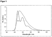
- the half-width (FWHM full width half maximum) is determined from the electroluminescence spectra.
- Table 1 summarizes the results of some OLEDs (Examples 4 to 7).
- the host materials or emitter materials according to the invention the compounds of Examples 1 and 2 are used.
- the host H1 and the emitter material D1 according to the prior art are used.
- organic electroluminescent devices containing the compounds of the invention have a longer lifetime in the case of the matrix example.
- organic electroluminescent devices comprising the compounds according to the invention as dopants have a significantly improved half-width in comparison with the prior art.
- Table 1 ⁇ / b> HTM1 HTM 2 ETM1 HTM 3 H1 D1 D2 Ex. 2
Description
- Die vorliegende Erfindung betrifft organische Halbleiter und deren Verwendung in organischen elektronischen Vorrichtungen.
- Organische Halbleiter werden für eine Reihe verschiedenartiger elektronischer Anwendungen entwickelt. Der Aufbau organischer Elektrolumineszenzvorrichtungen (OLEDs), in denen diese organischen Halbleiter als funktionelle Materialien eingesetzt werden, ist beispielsweise in
US 4539507 ,US 5151629 ,EP 0676461 undWO 98/27136 - Für fluoreszierende OLEDs werden gemäß dem Stand der Technik vor allem kondensierte Aromaten, insbesondere Anthracenderivate, als Host-materialien vor allem für blau emittierende Elektrolumineszenzvorrichtungen verwendet, z. B. 9,10-Bis(2-naphthyl)anthracen (
US 5935721 ). InWO 03/095445 CN 1362464 werden 9,10-Bis(1-naphthyl)-anthracen-Derivate für die Verwendung in OLEDs offenbart. Weitere Anthracenderivate sind inWO 01/076323 WO 01/021729 WO 04/013073 WO 04/018588 WO 03/087023 WO 04/018587 WO 04/016575 WO 08/145239 US 2004/131881 werden Fluorenederivate enthaltend mindestens ein kondensiertes Aromat für die Verwendung in OLEDs offenbart. Es ist für hochwertige Anwendungen wünschenswert, verbesserte Hostmaterialien zur Verfügung zu haben. Dasselbe gilt auch für Hostmaterialien für grün und rot fluoreszierende Dotanden. - Als Stand der Technik bei blau emittierenden Verbindungen kann die Verwendung von Arylvinylaminen genannt werden (z. B.
WO 04/013073 WO 04/016575 WO 04/018587 - Es besteht also weiterhin Bedarf an verbesserten Materialien, insbesondere Host-Materialien für fluoreszierende Emitter, vor allem für grün und rot fluoreszierende Emitter, aber auch für blau fluoreszierende Emitter, und fluoreszierenden Materialien, die thermisch stabil sind, die in organischen elektronischen Vorrichtungen zu guten Effizienzen und gleichzeitig zu hohen Lebensdauern führen, die bei der Herstellung und beim Betrieb der Vorrichtung zu reproduzierbaren Ergebnissen führen und die synthetisch einfach zugänglich sind. Auch bei Loch- und Elektronentransportmaterialien sind weitere Verbesserungen erforderlich.
- Überraschend wurde gefunden, dass Anthracenderivate, welche in 9- oder 9,10-Position substituiert sind und an welche in 1,2-Position oder 2,3-Position oder 3,4-Position und/oder in 5,6-Position oder 6,7-Position oder 7,8-Position eine Indenogruppe ankondensiert ist, sich sehr gut für die Verwendung in organischen Elektrolumineszenzvorrichtungen eignen. Dies gilt ebenso, wenn statt der Indenogruppe entsprechende heterocyclische Gruppen, wie zum Beispiel Indologruppen oder Benzothienylgruppen, ankondensiert sind. Mit diesen Verbindungen ist eine Steigerung der Effizienz und vor allem der Lebensdauer der organischen elektronischen Vorrichtung im Vergleich zu Materialien gemäß dem Stand der Technik möglich. Dies trifft insbesondere auf blau fluoreszierende Vorrichtungen zu. Weiterhin weisen diese Verbindungen eine hohe thermische Stabilität auf. Generell sind diese Materialien sehr gut für die Verwendung in organischen elektronischen Vorrichtungen geeignet, da sie eine hohe Glasübergangstemperatur aufweisen. Diese Materialien und deren Verwendung in organischen elektronischen Vorrichtungen sind daher der Gegenstand der vorliegenden Erfindung.
- Als nächstliegender Stand der Technik kann die
US 2002/132134 betrachtet werden. Darin werden kondensierte Aromaten offenbart, an welche zwei Aryl-substituierte Indenogruppen ankondensiert sind. Diese Verbindungen weisen jedoch einen großen Stokes-Shift auf, welcher möglicherweise verursacht ist durch die Rotationsfreiheitsgrade der Arylsubstituenten. Daher eignen sich die inUS 2002/132134 offenbarten Verbindungen nicht als Hostmaterial für tiefblaue Emitter. Hier besteht daher noch Verbesserungsbedarf. Weiterhin wäre es vorteilhaft, Verbindungen zur Verfügung zu haben, welche ein engeres Emissionsspektrum aufweisen. - Weiterhin ist als Emitter 9,10-Diphenylanthracen bekannt. Dieses weist zwar 100 % Fluoreszenzquanteneffizienz auf (H. Du et al., Photochemistry and Photobiology 1998, 68, 141-142), jedoch liegt die Emission zu weit im blauen Bereich, so dass diese Verbindung nicht als blauer Emitter verwendet werden kann.
- Der Übersichtlichkeit halber werden im Folgenden die Struktur und die Nummerierung des Anthracens dargestellt:

- Gegenstand der Erfindung sind daher Verbindungen gemäß der Formel (1) und (2),


- X
- ist bei jedem Auftreten gleich oder verschieden eine bivalente Brücke, ausgewählt aus C(R1)2;
- Ar
- ist bei jedem Auftreten gleich oder verschieden eine Arylgruppe mit 6 bis 10 C-Atomen oder eine Heteroarylgruppe mit 4 bis 9 C-Atomen;
- R1
- ist bei jedem Auftreten gleich oder verschieden methyl, ethyl, iso-Propyl, tert-Butyl, wobei ein H-Atom oder mehrere H-Atome durch F ersetzt sein können, oder eine Arylgruppe mit 6 bis 14 C-Atomen, die jeweils durch einen oder mehrere Reste R2 substituiert sein kann; dabei können zwei oder mehrere benachbarte Substituenten R1 auch miteinander ein mono- oder polycyclisches, aliphatisches oder aromatisches Ringsystem bilden;
- R
- ist bei jedem Auftreten gleich oder verschieden ein aromatisches oder heteroaromatisches Ringsystem mit 5 bis 14 aromatischen Ringatomen, das jeweils durch einen oder mehrere Reste R2 substituiert sein kann;
- R2
- ist bei jedem Auftreten gleich oder verschieden H, D, F, Cl, Methyl, Ethyl, n-Propyl, i-Propyl, n-Butyl, i-Butyl, s-Butyl, t-Butyl, wobei ein oder mehrere H-Atome durch F, Cl, oder CN ersetzt sein können;
- m
- ist 1;
- n
- ist 0 oder 1;
- In den Strukturen der Formel (1) und (2) bindet die Gruppe Ar über ein Kohlenstoffatom an das Anthracen und die Gruppe X bindet an ein benachbartes Kohlenstoffatom der Gruppe Ar und an ein benachbartes Kohlenstoffatom des Anthracens. Analog zum Indenofluoren sind hier für n = 1 auch cis- und trans-Diindenoanthracenderivate und entsprechende Derivate mit anderen ankondensierten Gruppen möglich, wobei Strukturen der Formel (1) zu trans-Derivaten und Strukturen der Formel (2) zu cis-Derivaten führen.
- Bevorzugt weisen die Verbindungen gemäß Formel (1) eine Glasübergangstemperatur TG von größer als 70 °C auf, besonders bevorzugt größer als 100 °C, ganz besonders bevorzugt größer als 130 °C.
- Eine Arylgruppe im Sinne dieser Erfindung enthält 6 bis 40 C-Atome; eine Heteroarylgruppe im Sinne dieser Erfindung enthält 2 bis 40 C-Atome und mindestens 1 Heteroatom, mit der Maßgabe, dass die Summe aus C-Atomen und Heteroatomen mindestens 5 ergibt. Die Heteroatome sind bevorzugt ausgewählt aus N, O und/oder S. Dabei wird unter einer Arylgruppe bzw. Heteroarylgruppe entweder ein einfacher aromatischer Cyclus, also Benzol, bzw. ein einfacher heteroaromatischer Cyclus, beispielsweise Pyridin, Pyrimidin, Thiophen, etc., oder eine kondensierte Aryl- oder Heteroarylgruppe, beispielsweise Naphthalin, Anthracen, Pyren, Chinolin, Isochinolin, etc., verstanden.
- Ein aromatisches Ringsystem im Sinne dieser Erfindung enthält 6 bis 40 C-Atome im Ringsystem. Ein heteroaromatisches Ringsystem im Sinne dieser Erfindung enthält 2 bis 40 C-Atome und mindestens ein Heteroatom im Ringsystem, mit der Maßgabe, dass die Summe aus C-Atomen und Heteroatomen mindestens 5 ergibt. Die Heteroatome sind bevorzugt ausgewählt aus N, O und/oder S. Unter einem aromatischen oder heteroaromatischen Ringsystem im Sinne dieser Erfindung soll ein System verstanden werden, das nicht notwendigerweise nur Aryl- oder Heteroarylgruppen enthält, sondern in dem auch mehrere Aryl- oder Heteroarylgruppen durch eine kurze, nicht-aromatische Einheit (bevorzugt weniger als 10 % der von H verschiedenen Atome), wie z. B. ein sp3-hybridisiertes C-, N- oder O-Atom, unterbrochen sein können. So sollen beispielsweise auch Systeme wie 9,9'-Spirobifluoren, 9,9-Diarylfluoren, Triarylamin, Diarylether, Stilben, Benzophenon, etc. als aromatische Ringsysteme im Sinne dieser Erfindung verstanden werden. Ebenso werden unter einem aromatischen bzw. heteroaromatischen Ringsystem Systeme verstanden, in denen mehrere Aryl- bzw. Heteroarylgruppen durch Einfachbindungen miteinander verknüpft sind, beispielsweise Biphenyl, Terphenyl oder Bipyridin.
- Im Rahmen der vorliegenden Erfindung werden unter einer C1- bis C40-Alkylgruppe, in der auch einzelne H-Atome oder CH2-Gruppen durch die oben genannten Gruppen substituiert sein können, besonders bevorzugt die Reste Methyl, Ethyl, n-Propyl, i-Propyl, n-Butyl, i-Butyl, s-Butyl, t-Butyl, 2-Methylbutyl, n-Pentyl, s-Pentyl, Cyclopentyl, n-Hexyl, Cyclohexyl, n-Heptyl, Cycloheptyl, n-Octyl, Cyclooctyl, 2-Ethylhexyl, Trifluormethyl, Pentafluorethyl oder 2,2,2-Trifluorethyl verstanden. Unter einer Alkenylgruppe werden im Sinne dieser Erfindung bevorzugt die Reste Ethenyl, Propenyl, Butenyl, Pentenyl, Cyclopentenyl, Hexenyl, Cyclohexenyl, Heptenyl, Cycloheptenyl, Octenyl oder Cyclooctenyl verstanden. Unter einer Alkinylgruppe werden im Sinne dieser Erfindung bevorzugt Ethinyl, Propinyl, Butinyl, Pentinyl, Hexinyl, Heptinyl oder Octinyl verstanden. Unter einer C1- bis C40-Alkoxygruppe werden besonders bevorzugt Methoxy, Trifluormethoxy, Ethoxy, n-Propoxy, i-Propoxy, n-Butoxy, i-Butoxy, s-Butoxy, t-Butoxy oder 2-Methylbutoxy verstanden. Unter einem aromatischen oder heteroaromatischen Ringsystem mit 5 - 40 aromatischen Ringatomen, welches noch jeweils mit den oben genannten Resten R substituiert sein kann und welches über beliebige Positionen am Aromaten bzw. Heteroaromaten verknüpft sein kann, werden insbesondere Gruppen verstanden, die abgeleitet sind von Benzol, Naphthalin, Anthracen, Phenanthren, Benzanthracen, Pyren, Chrysen, Perylen, Fluoranthen, Naphthacen, Pentacen, Benzpyren, Biphenyl, Biphenylen, Terphenyl, Terphenylen, Fluoren, Spirobifluoren, Dihydrophenanthren, Dihydropyren, Tetrahydropyren, cis- oder trans-Indenofluoren, Truxen, Isotruxen, Spirotruxen, Spiroisotruxen, Furan, Benzofuran, Isobenzofuran, Dibenzofuran, Thiophen, Benzothiophen, Isobenzothiophen, Dibenzothiophen, Pyrrol, Indol, Isoindol, Carbazol, Pyridin, Chinolin, Isochinolin, Acridin, Phenanthridin, Benzo-5,6-chinolin, Benzo-6,7-chinolin, Benzo-7,8-chinolin, Phenothiazin, Phenoxazin, Pyrazol, Indazol, Imidazol, Benzimidazol, Naphthimidazol, Phenanthrimidazol, Pyridimidazol, Pyrazinimidazol, Chinoxalinimidazol, Oxazol, Benzoxazol, Naphthoxazol, Anthroxazol, Phenanthroxazol, Isoxazol, 1,2-Thiazol, 1,3-Thiazol, Benzothiazol, Pyridazin, Benzopyridazin, Pyrimidin, Benzpyrimidin, Chinoxalin, 1,5-Diazaanthracen, 2,7-Diazapyren, 2,3-Diazapyren, 1,6-Diazapyren, 1,8-Diazapyren, 4,5-Diazapyren, 4,5,9,10-Tetraazaperylen, Pyrazin, Phenazin, Phenoxazin, Phenothiazin, Fluorubin, Naphthyridin, Azacarbazol, Benzocarbolin, Phenanthrolin, 1,2,3-Triazol, 1,2,4-Triazol, Benzotriazol, 1,2,3-Oxadiazol, 1,2,4-Oxadiazol, 1,2,5-Oxadiazol, 1,3,4-Oxadiazol, 1,2,3-Thiadiazol, 1,2,4-Thiadiazol, 1,2,5-Thiadiazol, 1,3,4-Thiadiazol, 1,3,5-Triazin, 1,2,4-Triazin, 1,2,3-Triazin, Tetrazol, 1,2,4,5-Tetrazin, 1,2,3,4-Tetrazin, 1,2,3,5-Tetrazin, Purin, Pteridin, Indolizin und Benzothiadiazol.
- Eine bevorzugte Ausführungsform der Verbindungen gemäß Formel (1) und (2) sind die Verbindungen der Formeln (3) bis (15),


- In einer bevorzugten Ausführungsform der Erfindung steht das Symbol Ar gleich oder verschieden bei jedem Auftreten für Benzol, Naphthalin, Thiophen, Pyrrol, Furan, Pyridin, Pyrimidin, Pyrazin, Pyridazin, Chinolin, Chinoxalin, Triazin, Triazol, Imidazol, Benzimidazol, Benzothiophen, Indol und Benzofuran, insbesondere für Benzol, Naphthalin oder Thiophen.
- In einer bevorzugten Ausführungsform der Erfindung sind die beiden Gruppen Ar für n = 1 gleich gewählt. Dies begründet sich mit der besseren synthetischen Zugänglichkeit der Verbindungen.
- Von den Verbindungen der Formeln (3) bis (15) sind insbesondere die Verbindungen der Formeln (3), (4) und (5) bevorzugt, da diese ausgehend von synthetisch leicht zugänglichem 2-Bromanthrachinon für n = 1 synthetisiert werden können.
- Eine besonders bevorzugte Ausführungsform der Verbindungen gemäß den Formeln (3) bis (15) sind die Verbindungen der Formeln (3a) bis (15a), (3b) bis (15b) und (3c) bis (15c),


- Der Index m = 1, d. h. es handelt sich bei der zentralen Einheit um ein Anthracen.
- Die Gruppe X steht für C(R1)2. Dabei sei hier nochmals explizit darauf hingewiesen, dass hier für X = C(R1)2 die Reste R1 auch miteinander ein aromatisches oder aliphatisches Ringsystem bilden können. Wenn mehrere Reste R1 an einer Gruppe C(R1)2 miteinander ein Ringsystem bilden, führt dies zu Spirostrukturen. Die Ausbildung derartiger Spirostrukturen durch Bildung von Ringsystemen zwischen zwei Gruppen R1 an C(R1)2 ist eine weitere bevorzugte Ausführungsform der Erfindung. Dies gilt insbesondere, wenn R1 für eine substituierte oder unsubstituierte Phenylgruppe steht und die beiden Phenylgruppen zusammen mit dem C-Atom der Brücke ein Ringsystem bilden.
- Beispiele für bevorzugte Verbindungen gemäß den Formeln (1) bis (15) bzw. (3a) bis (15a) bzw. (3b) bis (15b) bzw. (3c) bis (15c) sind die im Folgenden abgebildeten Strukturen (1) bis (134) (*nicht erfindungsgmäß).


(1) (2) 

(3) (4) 

(5) (6) 

(7) (8) 

(9) (10) 

(11) (12) 

(13) (14) 

(15) (16) 

(17) (18) 

(19) (20) 

(21) (22) 

(23) (24) 

(25) (26) 

(27) (28) 

(29) (30) 

(31)* (32)* 

(33)* (34)* 

(35)* (36)* 

(37)* (38)* 

(39) (40) 

(41) (42) 

(43)* (44) 

(45)* (46)* 

(47)* (48)* 

(49)* (50)* 

(51) (52) 

(53) (54)* 

(55)* (56)* 

(57) (58) 

(59) (60)* 

(61)* (62)* 

(63)* (64)* 

(65)* (66)* 

(67)* (68)* 

(69)* (70)* 

(71)* (72) 

(73)* (74)* 

(75)* (76)* 

(77)* (78)* 

(79)* (80)* 

(81)* (82)* 

(83)* (84)* 

(85)* (86)* 

(87) (88) 

(89) (90)* 

(91)* (92)* 

(93)* (94)* 

(95) (96) 

(97)* (98)* 

(99)* (100)* 

(101)* (102)* 

(103)* (104)* 

(105)* (106)* 

(107)* (108) 

(109)* (110)* 

(111)* (112)* 

(113)* (114)* 

(115)* (116)* 

(117)* (118)* 

(119) (120)* 

(121)* (122)* 

(123)* (124)* 

(125) (126) 

(127)* (128) 

(129)* (130)* 

(131)* (132)* 

(133)* (134)* - Die erfindungsgemäßen Verbindungen gemäß Formel (1) und (2) können nach dem Fachmann bekannten Syntheseschritten hergestellt werden. Die Synthese ist im folgenden Schema 1 beispielhaft abgebildet. Als Ausgangsverbindung eignet sich 2,6-Dibromanthrachinon, welches aus 2,6-Diaminoanthrachinon durch Diazotierung und Umsetzung mit CuBr2 erhalten werden kann. Die Reste R können in Form einer Arylmetallverbindung, beispielsweise einer Aryllithiumverbindung oder einer Aryl-Grignard-Verbindung eingeführt werden, gefolgt von Reduktion der gebildeten Alkohole. Das Bromid kann durch Umsetzung mit einer Diborverbindung, beispielsweise Bis(pinacolato)dibor, unter Palladiumkatalyse in das entsprechende Boronsäurederivat umgewandelt werden, welches in einer Suzuki-Kupplung mit einem 2-Halogenalkylbenzoat umgesetzt werden kann. Die Reste an der Brücke X werden dann durch Umsetzung mit einer Aryllithiumverbindung oder einer Aryl-Grignard-Verbindung eingeführt, und die Cyclisierung zur Verbindung der Formel (1) bzw. (2) erfolgt unter sauren Bedingungen. Je nach den genauen Cyclisierungsbedingungen können bei der Cyclisierung auch Gemische entstehen, welche entweder getrennt werden können oder auch als Gemisch in der organischen Elektrolumineszenzvorrichtung eingesetzt werden können.

- Analog hierzu lassen sich auch anders substituierte Verbindungen herstellen, bzw. es lassen sich andere Derivate der Formel (1) oder (2) herstellen, indem andere Dihalogenanthrachinone verwendet werden.
- Ein weiterer Gegenstand der Erfindung ist ein Verfahren zur Herstellung der Verbindungen gemäß Formel (1) und (2) aus einem Dihalogenanthrachinon, umfassend die Reaktionsschritte:
- a) Addition einer Arylmetallverbindung,
- b) Reduktion zum Anthracen,
- c) Kupplung mit einem funktionalisierten Aromaten, gegebenenfalls nach Umwandlung der Halogenfunktionalität in einer Boronsäurefunktionalität, und
- d) Ringschluss, bevorzugt unter sauren Bedingungen.
- Die oben beschriebenen erfindungsgemäßen Verbindungen, insbesondere Verbindungen, welche mit reaktiven Abgangsgruppen, wie Brom, lod, Boronsäure oder Boronsäureester, substituiert sind, können als Monomere zur Erzeugung entsprechender Dimere, Trimere, Tetramere, Pentamere, Oligomere, Polymere oder als Kern von Dendrimeren Verwendung finden. Die Oligomerisation bzw. Polymerisation erfolgt dabei bevorzugt über die Halogenfunktionalität bzw. die Boronsäurefunktionalität.
- Weiterer Gegenstand der Erfindung sind daher Dimere, Trimere, Tetramere, Pentamere, Oligomere, Polymere oder Dendrimere enthaltend eine oder mehrere Verbindungen gemäß Formel (1) und/oder (2), wobei ein oder mehrere Reste R, R1 oder R2 Bindungen zwischen den Verbindungen gemäß Formel (1) bzw. (2) im Dimer, Trimer, Tetramer bzw. Pentamer bzw. Bindungen der Verbindung gemäß Formel (1) bzw. (2) zum Polymer, Oligomer oder Dendrimer darstellen. Unter einem Oligomer im Sinne dieser Erfindung wird eine Verbindung verstanden, welche mindestens sechs Einheiten gemäß Formel (1) und/oder (2) aufweist. Die Polymere, Oligomere oder Dendrimere können konjugiert, teilkonjugiert oder nichtkonjugiert sein. Die Trimere, Tetramere, Pentamere, Oligomere oder Polymere können linear oder verzweigt sein. In den linear verknüpften Strukturen können die Einheiten gemäß Formel (1) und/oder (2) sowohl direkt miteinander verknüpft sein oder sie können über eine bivalente Gruppe, beispielsweise über eine substituierte oder unsubstituierte Alkylengruppe, über ein Heteroatom oder über eine bivalente aromatische oder heteroaromatische Gruppe, miteinander verknüpft sein. In verzweigten Strukturen können beispielsweise drei oder mehrere Einheiten gemäß Formel (1) und/oder (2) über eine trivalente oder höhervalente Gruppe, beispielsweise über eine trivalente oder höhervalente aromatische oder heteroaromatische Gruppe, zu einem verzweigten Trimer, Tetramer, Pentamer, Oligomer oder Polymer verknüpft sein.
- Für die Wiederholeinheiten gemäß Formel (1) und (2) in Dimeren, Trimeren, Tetrameren, Pentameren, Oligomeren und Polymeren gelten dieselben Bevorzugungen wie oben beschrieben.
- Zur Herstellung der Oligomere oder Polymere werden die erfindungsgemäßen Monomere homopolymerisiert oder mit weiteren Monomeren copolymerisiert. Geeignete und bevorzugte Comonomere sind gewählt aus Fluorenen (z. B. gemäß
EP 842208 WO 00/22026 EP 707020 EP 894107 WO 06/061181 WO 92/18552 WO 04/070772 WO 04/113468 EP 1028136 ), Dihydrophenanthrenen (z. B. gemäßWO 05/014689 WO 04/041901 WO 04/113412 WO 05/040302 WO 05/104264 WO 07/017066 WO 07/068325 WO 06/003000 - Die erfindungsgemäßen Verbindungen gemäß Formel (1) und (2) eignen sich für den Einsatz in elektronischen Vorrichtungen, insbesondere in organischen Elektrolumineszenzvorrichtungen (OLEDs, PLEDs). Abhängig von der Substitution werden die Verbindungen in unterschiedlichen Funktionen und Schichten eingesetzt.
- Ein weiterer Gegenstand der Erfindung ist daher die Verwendung von Verbindungen gemäß Formel (1) bzw. Formel (2) in elektronischen Vorrichtungen, insbesondere in organischen Elektrolumineszenzvorrichtungen.
- Nochmals ein weiterer Gegenstand der Erfindung sind organische elektronische Vorrichtungen, enthaltend mindestens eine Verbindung gemäß Formel (1) und/oder (2), insbesondere organische Elektrolumineszenzvorrichtungen, enthaltend Anode, Kathode und mindestens eine emittierende Schicht, dadurch gekennzeichnet, dass mindestens eine organische Schicht, die eine emittierende Schicht oder eine andere Schicht sein kann, mindestens eine Verbindung gemäß Formel (1) und/oder (2) enthält.
- Außer Kathode, Anode und der emittierenden Schicht kann die organische Elektrolumineszenzvorrichtung noch weitere Schichten enthalten. Diese sind beispielsweise gewählt aus jeweils einer oder mehreren Lochinjektionsschichten, Lochtransportschichten, Lochblockierschichten, Elektronentransportschichten, Elektroneninjektionsschichten, Elektronenblockierschichten, Charge-Generation Layers (IDMC 2003, Taiwan; Session 21 OLED (5), T. Matsumoto, T. Nakada, J. Endo, K. Mori, N. Kawamura, A. Yokoi, J. Kido, Multiphoton Organic EL Device Having Charge Generation Layer) und/oder organischen oder anorganischen p/n-Übergängen. Es sei aber darauf hingewiesen, dass nicht notwendigerweise jede dieser Schichten vorhanden sein muss und die Wahl der Schichten immer von den verwendeten Verbindungen abhängt und insbesondere auch von der Tatsache, ob es sich um eine fluoreszierende oder phosphoreszierende Elektrolumineszenzvorrichtung handelt.
- In einer weiteren bevorzugten Ausführungsform der Erfindung enthält die organische Elektrolumineszenzvorrichtung mehrere emittierende Schichten, wobei mindestens eine organische Schicht mindestens eine Verbindung gemäß Formel (1) oder (2) enthält. Besonders bevorzugt weisen diese Emissionsschichten insgesamt mehrere Emissionsmaxima zwischen 380 nm und 750 nm auf, so dass insgesamt weiße Emission resultiert, d. h. in den emittierenden Schichten werden verschiedene emittierende Verbindungen verwendet, die fluoreszieren oder phosphoreszieren können und die blaues und gelbes, orange oder rotes Licht emittieren. Insbesondere bevorzugt sind Dreischichtsysteme, also Systeme mit drei emittierenden Schichten, wobei mindestens eine dieser Schichten mindestens eine Verbindung gemäß Formel (1) oder (2) enthält und wobei die drei Schichten blaue, grüne und orange oder rote Emission zeigen (für den prinzipiellen Aufbau siehe z. B.
WO 05/011013 - In einer bevorzugten Ausführungsform der Erfindung werden die Verbindungen gemäß Formel (1) und (2) als Hostmaterial für fluoreszierende Dotanden eingesetzt, insbesondere für grün und rot fluoreszierende Dotanden. In diesem Fall ist bevorzugt die Gruppe X eine C(R1)2-Gruppe, die Gruppe Ar ist eine Arylgruppe und die Gruppen R sind H, eine Alkylgruppe oder eine Arylgruppe, wobei mindestens eine Gruppe R eine Alkyl- oder Arylgruppe darstellt; bevorzugt stellen beide Gruppen R Arylgruppen dar. Dieselben Bevorzugungen gelten für die Gruppen X, Ar und R in Strukturen gemäß Formel (3) bis (15), (3a) bis (15a), (3b) bis (15b) und (3c) bis (15c).
- Unter einem Hostmaterial wird in einem System aus Host und Dotand diejenige Komponente verstanden, die in dem System im höheren Anteil vorliegt. Bei einem System aus einem Host und mehreren Dotanden wird als Host diejenige Komponente verstanden, deren Anteil der höchste in der Mischung ist.
- Der Anteil des Hostmaterials gemäß Formel (1) bzw. (2) in der emittierenden Schicht beträgt zwischen 50.0 und 99.9 Vol.-%, bevorzugt zwischen 80.0 und 99.5 Vol.-%, besonders bevorzugt zwischen 90.0 und 99.0 Vol.-%. Entsprechend beträgt der Anteil des Dotanden zwischen 0.1 und 50.0 Vol.-%, bevorzugt zwischen 0.5 und 20.0 Vol.-%, besonders bevorzugt zwischen 1.0 und 10.0 Vol.-%.
- Bevorzugte Dotanden in fluoreszierenden Vorrichtungen sind gewählt aus der Klasse der Monostyrylamine, der Distyrylamine, der Tristyrylamine, der Tetrastyrylamine und der Arylamine. Unter einem Monostyrylamin wird eine Verbindung verstanden, die eine Styrylgruppe und mindestens ein Amin enthält, welches bevorzugt aromatisch ist. Unter einem Distyrylamin wird eine Verbindung verstanden, die zwei Styrylgruppen und mindestens ein Amin enthält, welches bevorzugt aromatisch ist. Unter einem Tristyrylamin wird eine Verbindung verstanden, die drei Styrylgruppen und mindestens ein Amin enthält, welches bevorzugt aromatisch ist. Unter einem Tetrastyrylamin wird eine Verbindung verstanden, die vier Styrylgruppen und mindestens ein Amin enthält, welches bevorzugt aromatisch ist. Unter einem Arylamin bzw. einem aromatischen Amin im Sinne dieser Erfindung wird eine Verbindung verstanden, die drei aromatische oder heteroaromatische Ringsysteme direkt an den Stickstoff gebunden enthält, davon bevorzugt mindestens ein kondensiertes Ringsystem mit mindestens 14 aromatischen Ringatomen. Die Styrylgruppen sind besonders bevorzugt Stilbene, die auch an der Doppelbindung oder an den Aromaten weiter substituiert sein können. Beispiele für derartige Dotanden sind substituierte oder unsubstituierte Tristilbenamine oder weitere Dotanden, die beispielsweise in
WO 06/000388 WO 06/058737 WO 06/000389 WO 07/065549 WO 07/115610 WO 06/122630 WO 08/006449 WO 07/140847 - Geeignete Dotanden, für welche die Verbindung gemäß Formel (1) bzw. Formel (2) ein geeignetes Hostmaterial sind, sind weiterhin die in der folgenden Tabelle abgebildeten Strukturen sowie die in
JP 06/001973 WO 04/047499 WO 06/098080 WO 07/065678 US 2005/0260442 undWO 04/092111 
- In einer weiteren bevorzugten Ausführungsform der Erfindung werden die Verbindungen gemäß Formel (1) und (2) als emittierende Materialien eingesetzt. Die Verbindungen sind insbesondere dann bevorzugt, wenn die Reste R für ein aromatisches oder heteroaromatisches Ringsystem stehen. Dies führt zu emittierenden Verbindungen, welche tiefblaue Emission mit einem sehr engen Emissionsspektrum zeigen. Die Verbindungen sind weiterhin dann als emittierende Verbindungen geeignet, wenn mindestens ein Substituent R mindestens eine Vinylaryl-Einheit, mindestens eine Vinylarylamin-Einheit und/oder mindestens eine Arylamino- bzw. Diarylamino-Einheit enthält. Bevorzugte Arylaminoeinheiten sind die Gruppen der vorne abgebildeten Formeln (16) und (17). Dieselben Bevorzugungen gelten für die Gruppen R in Strukturen gemäß Formel (3) bis (15) und (3a) bis (15a) bzw. (3b) bis (15b) bzw. (3c) bis (15c). Besonders bevorzugte Dotanden sind solche, in welchen entweder zwei Reste R für Gruppen der Formel (16) oder (17) stehen oder in welchen ein Rest R für eine Gruppe der Formel (16) oder (17) steht und der andere Reste R für H, eine Alkylgruppe oder eine Arylgruppe stehen.
- Der Anteil der Verbindung gemäß Formel (1) bzw. (2) in der Mischung der emittierenden Schicht beträgt zwischen 0.1 und 50.0 Vol.-%, bevorzugt zwischen 0.5 und 20.0 Vol.-%, besonders bevorzugt zwischen 1.0 und 10.0 Vol.-%. Entsprechend beträgt der Anteil des Hostmaterials zwischen 50.0 und 99.9 Vol.-%, bevorzugt zwischen 80.0 und 99.5 Vol.-%, besonders bevorzugt zwischen 90.0 und 99.0 Vol.-%.
- Als Hostmaterialien kommen hierfür Materialien verschiedener Stoffklassen in Frage. Bevorzugte Hostmaterialien sind ausgewählt aus den Klassen der Oligoarylene (z. B. 2,2',7,7'-Tetraphenylspirobifluoren gemäß
EP 676461 EP 676461 WO 04/081017 WO 04/058911 WO 05/084081 WO 05/084082 WO 06/048268 -
WO 06/117052 WO 08/145239 - Geeignete Hostmaterialien sind weiterhin die in der folgenden Tabelle abgebildeten Materialien, sowie Derivate dieser Materialien, wie sie in
WO 04/018587 WO 08/006449 US 5935721 ,US 2005/0181232 ,JP 2000/273056 EP 681019 US 2004/0247937 undUS 2005/0211958 offenbart werden.
- In nochmals einer weiteren Ausführungsform der Erfindung werden die Verbindungen gemäß Formel (1) und (2) als Lochtransportmaterial bzw. als Lochinjektionsmaterial eingesetzt. Die Verbindungen sind dann bevorzugt mit mindestens einer Gruppe N(Ar1)2 substituiert, bevorzugt mit mindestens zwei Gruppen N(Ar1)2 und/oder sie enthalten weitere Gruppen, die den Lochtransport verbessern. Die Gruppen N(Ar1)2 sind bevorzugt ausgewählt aus den oben beschriebenen Formeln (16) oder (17). Dies gilt insbesondere für die Reste R an den Strukturen gemäß Formel (3) bis (15) bzw. (3a) bis (15a) bzw. (3b) bis (15b) bzw. (3c) bis (15c). Weitere bevorzugte Gruppen, die den Lochtransport verbessern, sind beispielsweise die Gruppen N(R1), S oder O, insbesondere N(R1) als verbrückende Einheit X oder elektronenreiche Heteroaromaten, insbesondere Thiophen, Pyrrol oder Furan als Gruppe Ar. Die Verbindung wird bevorzugt in einer Lochtransport- bzw. in einer Lochinjektionsschicht eingesetzt. Eine Lochinjektionsschicht im Sinne dieser Erfindung ist eine Schicht, die direkt an die Anode angrenzt. Eine Lochtransportschicht im Sinne dieser Erfindung ist eine Schicht, die zwischen einer Lochinjektionsschicht und einer Emissionsschicht liegt. Wenn die Verbindungen gemäß Formel (1) bzw. (2) als Lochtransport- bzw. als Lochinjektionsmaterial verwendet werden, kann es bevorzugt sein, wenn sie mit Elektronenakzeptor-Verbindungen dotiert werden, beispielsweise mit F4-TCNQ oder mit Verbindungen, wie in
EP 1476881 oderEP 1596445 beschrieben. - In nochmals einer weiteren Ausführungsform der Erfindung werden die Verbindungen gemäß Formel (1) und (2) als Elektronentransportmaterial eingesetzt. Hier ist es bevorzugt, wenn eine oder beide verbrückenden Gruppen X, bevorzugt beide, für C=O, P(=O), SO oder SO2 stehen und die Substituenten R für H, eine Alkylgruppe, eine Arylgruppe oder eine Heteroarylgruppe, welche einen elektronenarmen Heterocyclus darstellt. Weiterhin ist es hier bevorzugt, wenn die verbrückenden Gruppen X für C(R1)2 stehen und ein oder beide Substituenten R einen elektronenarmen Heterocyclus enthalten, wie beispielsweise Imidazol, Pyrazol, Thiazol, Benzimidazol, Benzothiazol, Triazol, Oxadiazol, Benzothiadiazol, Phenanthrolin, etc. Dies gilt insbesondere für die Gruppen X und R an den Strukturen gemäß Formel (3) bis (14) bzw. (3a) bis (14a) bzw. (3b) bis (14b) bzw. (3c) bis (14c). Weiterhin kann es bevorzugt sein, wenn die Verbindung mit Elektronendonorverbindungen dotiert ist.
- Geeignete Ladungstransportmaterialien, wie sie in der Lochinjektions- bzw. Lochtransportschicht oder in der Elektronentransportschicht der erfindungsgemäßen organischen Elektrolumineszenzvorrichtung verwendet werden können, sind außer den erfindungsgemäßen Materialiene beispielsweise die in Y. Shirota et al., Chem. Rev. 2007, 107(4), 953-1010 offenbarten Verbindungen oder andere Materialien, wie sie gemäß dem Stand der Technik in diesen Schichten eingesetzt werden.
- Geeignete Lochtransport- oder Lochinjektionsmaterialien, die in der erfindungsgemäßen Elektrolumineszenzvorrichtung enthaltend eine Verbindung der Formel (1) oder (2) verwendet werden können, sind beispielsweise die in der folgenden Tabelle aufgeführten Materialien.


- Weiterhin geeignete Lochtransport- und Lochinjektionsmaterialien sind Derivate der oben abgebildeten Verbindungen, wie sie in
JP 2001/226331 EP 676461 EP 650955 WO 01/049806 US 4780536 ,WO 98/30071 EP 891121 EP 1661888 ,JP 2006/253445 EP 650955 WO 06/073054 US 5061569 undWO 06/122630 - Geeignete Elektronentransport- oder Elektroneninjektionsmaterialien, die in der erfindungsgemäßen Elektrolumineszenzvorrichtung enthaltend eine Verbindung der Formel (1) oder (2) verwendet werden können, sind beispielsweise die in der folgenden Tabelle aufgeführten Materialien.

- Weiterhin geeignete Elektronentransport- und Elektroneninjektionsmaterialien sind Derivate der oben abgebildeten Verbindungen, wie sie in
JP 2000/053957 WO 03/060956 WO 04/028217 WO 04/080975 - Auch in Polymeren können Wiederholeinheiten gemäß Formel (1) und (2) entweder als Polymergrundgerüst (Backbone), als emittierende Einheit, als lochtransportierende Einheit und/oder als elektronentransportierende Einheit eingesetzt werden. Dabei entsprechen die bevorzugten Substitutionsmuster den oben beschriebenen.
- Weiterhin bevorzugt ist eine organische Elektrolumineszenzvorrichtung, dadurch gekennzeichnet, dass eine oder mehrere Schichten mit einem Sublimationsverfahren beschichtet werden. Dabei werden die Materialien in Vakuum-Sublimationsanlagen bei einem Anfangsdruck von üblicherweise kleiner 10-5 mbar, bevorzugt kleiner 10-6 mbar aufgedampft. Es ist aber auch möglich, dass der Anfangsdruck noch geringer ist, beispielsweise kleiner 10-7 mbar.
- Bevorzugt ist ebenfalls eine organische Elektrolumineszenzvorrichtung, dadurch gekennzeichnet, dass eine oder mehrere Schichten mit dem OVPD (Organic Vapour Phase Deposition) Verfahren oder mit Hilfe einer Trägergassublimation beschichtet werden. Dabei werden die Materialien bei einem Druck zwischen 10-5 mbar und 1 bar aufgebracht. Ein Spezialfall dieses Verfahrens ist das OVJP (Organic Vapour Jet Printing) Verfahren, bei dem die Materialien direkt durch eine Düse aufgebracht und so strukturiert werden (z. B. M. S. Arnold et al., Appl. Phys. Lett. 2008, 92, 053301).
- Weiterhin bevorzugt ist eine organische Elektrolumineszenzvorrichtung, dadurch gekennzeichnet, dass eine oder mehrere Schichten aus Lösung, wie z. B. durch Spincoating, oder mit einem beliebigen Druckverfahren, wie z. B. Siebdruck, Flexodruck oder Offsetdruck, besonders bevorzugt aber LITI (Light Induced Thermal Imaging, Thermotransferdruck) oder Ink-Jet Druck (Tintenstrahldruck), hergestellt werden. Hierfür sind lösliche Verbindungen nötig. Hohe Löslichkeit lässt sich durch geeignete Substitution der Verbindungen erreichen.
- Die erfindungsgemäßen Verbindungen weisen bei Verwendung in organischen Elektrolumineszenzvorrichtungen folgende überraschende Vorteile gegenüber dem Stand der Technik auf:
- 1. Die erfindungsgemäßen Verbindungen weisen eine hohe thermische Stabilität auf und lassen sich unzersetzt sublimieren.
- 2. Die erfindungsgemäßen Verbindungen, insbesondere solche, in denen R für ein aromatisches oder heteroaromatisches Ringsystem steht oder die mit Diarylaminosubstituenten substituiert sind, weisen sehr gute blaue bzw. grüne Farbkoordinaten auf und eignen sich daher sehr gut als blaue Emitter. Weiterhin weisen die Verbindungen einen geringen Stokes-Shift und ein sehr schmales Emissionsspektrum auf.
- 3. Die erfindungsgemäßen Verbindungen eignen sich sehr gut als Hostmaterial, insbesondere für rot und grün fluoreszierende Dotanden.
- 4. Die erfindungsgemäßen Verbindungen, insbesondere solche, welche mit Diarylaminogruppen substituitert sind und/oder welche S, O oder N(R1) in der Brücke X enthalten und/oder welche elektronenreiche Heteroaromaten als Gruppe Ar enthalten, eignen sich sehr gut für die Verwendung als Lochinjektions- und Lochtransportmaterial und führen zu einer Verringerung der Betriebsspannung.
- 5. Die mit den erfindungsgemäßen Verbindungen hergestellten OLEDs weisen eine sehr hohe Lebensdauer auf.
- 6. Die mit den erfindungsgemäßen Verbindungen hergestellten OLEDs weisen eine sehr hohe Quanteneffizienz auf.
- Im vorliegenden Anmeldetext wird auf die Verwendung der erfindungsgemäßen Verbindungen in Bezug auf OLEDs und PLEDs und die entsprechenden Displays abgezielt. Trotz dieser Beschränkung der Beschreibung ist es für den Fachmann ohne weiteres erfinderisches Zutun möglich, die erfindungsgemäßen Verbindungen auch in anderen elektronischen Vorrichtungen einzusetzen, z. B. in organischen Feld-Effekt-Transistoren (O-FETs), organischen Dünnfilmtransistoren (O-TFTs), organischen lichtemittierenden Transistoren (O-LETs), organischen integrierten Schaltungen (O-ICs), organischen Solarzellen (O-SCs), organischen Feld-Quench-Devices (O-FQDs), lichtemittierenden elektrochemischen Zellen (LECs), organischen Laserdioden (O-Laser) oder organischen Photorezeptoren.
- Die Verwendung der erfindungsgemäßen Verbindungen in den entsprechenden Vorrichtungen ebenso wie diese Vorrichtungen selbst sind ebenfalls ein Gegenstand der vorliegenden Erfindung.
- Die Erfindung wird durch die nachfolgenden Beispiele genauer beschrieben, ohne sie dadurch einschränken zu wollen.
- Die nachfolgenden Synthesen werden, sofern nicht anders angegeben, unter einer Schutzgasatmosphäre in getrockneten Lösungsmitteln durchgeführt. Die Edukte können von ALDRICH bezogen werden.
-

- 62.6 g (255 mmol) 2,6-Diaminoanthrachinon und 124 g (550 mmol) CuBr2 werden in 1000 mL Acetonitril vorgelegt und 68 mL (515 mmol) tert-Butylnitrit bei 60 °C Innentemperatur zugetropft. Nach 30 min. wird das Reaktionsgemisch in ein Gemisch aus 150 mL konzentrierte HCl und 1 L Eiswasser gegossen, der entstandene Feststoff abgesaugt, mit Wasser, EtOH und Heptan gewaschen und getrocknet. Man erhält 89 g (243 mmol, 96 %) eines braunen Feststoffes, der im 1H-NMR einheitlich ist und der ohne weitere Reinigung in die Folgereaktion eingesetzt wird.
-

- 36.6 g (100 mmol) 2,6-Dibromanthrachinon werden in 600 mL THF gelöst, auf -75 °C abgekühlt und 100 mL einer 2 M Phenyllithiumlösung in THF zugetropft. Nach 2 h lässt man auf RT kommen, gibt 50 mL einer 4 M HCl zu, extrahiert zwischen Toluol und Wasser, trocknet die organische Phase über Na2SO4 und entfernt das Lösungsmittel im Vakuum. Der Rückstand wird in 350 mL DMF aufgenommen, 68 g (350 mmol) SnCl2 zugegeben und für 2 h auf eine Innentemperatur von 140 °C gebracht. Danach gibt man bei ca. 40 °C 180 mL 2 M HCl zu, saugt den Niederschlag ab, wäscht mit Wasser, EtOH und Essigsäureethylester und trocknet bei 80 °C im Vakuum. Nach Umkristallisation aus Toluol erhält man 30.8 g (63 mmol, 63 %) eines ockerfarbenen Feststoffes, der nach DC- und 1H-NMR einheitlich ist und in dieser Form in der Folgereaktion eingesetzt wird.
-

- 9.5 g (19.5 mmol) 2,6-Dibrom-9,10-diphenylanthracen werden in 240 mL trockenem Dioxan gelöst, 16.3 g (64 mmol) Bis(pinacolato)dibor, 1 g (1.2 mmol) [1,1'-Bis(diphenylphosphino)ferrocen]palladium(II)chlorid (Komplex mit Dichlormethan (1:1), Pd-Gehalt: 13 %) und 23 g (234 mmol) Kaliumacetat zugegeben, das Gemisch für 2 h zum Sieden erhitzt, in Eiswasser gegossen, der Niederschlag abgesaugt, mit EtOH gewaschen und im Vakuum getrocknet. Man erhält 10 g (17.1 mmol, 88 %) eines fahlgelben, DC- und 1H-NMR einheitlichen Pulvers.
-

- 9.4 g (16 mmol) 9,10-Diphenylanthracen-2,6-diboronsäurepinacolester werden 4 h in einer Mischung aus 115 mL EtOH, 115 mL Toluol, 60 mL einer 2 M Na2CO3-Lösung, 4.5 mL (32.3 mmol) Methyl-2-brombenzoat und 750 mg (0.7 mmol) Pd(PPh3)4 zum Sieden erhitzt. Im Anschluss wird die Reaktionsmischung in eine Mischung aus Eiswasser/MeOH/HCl 1:1:1 gegossen, der farblose Niederschlag abgesaugt, mit Wasser, EtOH und Heptan gewaschen und getrocknet. Der Feststoff wird in siedendem Toluol gelöst, über eine Kieselgelschicht filtriert, das Filtrat mit Heptan versetzt und das ausgefallene Produkt abgesaugt. Man erhält 8.9 g (14.8 mmol, 92 %) des Diesters als farbloses Pulver.
-

- 8.9 g (14.9 mmol) des Diesters werden bei RT mit 180 ml einer 0.5 M Phenylmagnesiumbromid-Lösung (90 mmol) in THF versetzt und für 3 h zum Sieden erhitzt. Nach dieser Zeit werden 50 mL 50%ige Essigsäure zugetropft, das Lösungsmittel im Vakuum entfernt, der verbliebene Feststoff in MeOH aufgenommen, abgesaugt und mit MeOH gewaschen und getrocknet. Es verbleiben 11.3 g (13.3 mmol, 90 %) eines farblosen Feststoffes, der nach DC und 1H-NMR einen Reinheitsgrad von >98% aufwies.
-

- 10.3 g (12.2 mmol) des Diols werden für 2 h in einer Mischung aus 70 mL Eisessig und 1 mL konz. HCl zum Sieden erhitzt. Nach erfolgtem Umsatz wird der ausgefallene Feststoff abgesaugt, mit Wasser, EtOH und Heptan gewaschen und getrocknet. Nach vierfacher Umkristallisation aus Chlorbenzol und zweifacher Sublimation im Vakuum (T = 340 °C, p = 1 x 10⁻⁵ mbar) verbleiben 6 g (7.4 mmol, 61 %) in Form eines blassgelben Glases mit einer durch RP-HPLC bestimmten Reinheit von >99.9%.
-

- Die Synthese dieser Verbindung erfolgt analog zu Beispiel 1, wobei 2-Aminoanthrachinon als Ausgangsverbindung eingesetzt wird.
- Die Herstellung von OLEDs erfolgt nach einem Verfahren, das in
WO 04/058911 - In den folgenden Beispielen 4 bis 7 werden die Ergebnisse verschiedener OLEDs vorgestellt. Glasplatten, die mit strukturiertem ITO (Indium Zinn Oxid) beschichtet sind, bilden die Substrate der OLEDs. Die OLEDs bestehen aus folgender Schichtenfolge: Substrat / Lochinjektionsschicht (HTM1) 60 nm / Lochtransportschicht (HTM2) 20 nm / Emissionschicht (EML) 30 nm / Elektronentransportschicht (ETM) 20 nm und abschließend eine Kathode. Die Materialien werden in einer Vakuumkammer thermisch aufgedampft. Dabei besteht die Emissionsschicht immer aus einem Matrixmaterial (Host) und einem Dotierstoff (Dotand), der durch Coverdampfung dem Host beigemischt wird. Die Kathode wird durch eine 1 nm dünne LiF-Schicht und einer darauf abgeschiedenen 100 nm AI-Schicht gebildet. Die Tabelle 1 zeigt die chemischen Strukturen der zum Aufbau der OLEDs verwendeten Materialien.
- Diese OLEDs werden standardmäßig charakterisiert; hierfür werden die Elektrolumineszenzspektren, die Effizienz (gemessen in cd/A), die Leistungseffizienz (gemessen in lm/W) in Abhängigkeit der Helligkeit, berechnet aus Strom-Spannungs-Helligkeit-Kennlinien (IUL-Kennlinien), und die Lebensdauer bestimmt. Als Lebensdauer wird die Zeit definiert, nach der die Anfangshelligkeit von 25000 cd/m2 auf die Hälfte gesunken ist. Aus den Elektrolumineszenzspektren wird die Halbwertsbreite (FWHM= full width half maximum) bestimmt.
- In Tabelle 1 sind die Ergebnisse einiger OLEDs (Beispiele 4 bis 7) zusammengefasst. Als erfindungsgemäße Hostmaterialien bzw. Emittermaterialien werden die Verbindungen der Beispiele 1 und 2 verwendet. Als Vergleichsbeispiele werden der Host H1 bzw. das Emittermaterial D1 gemäß dem Stand der Technik verwendet.
- Wie man aus den Ergebnissen in Tabelle 2 deutlich erkennen kann, weisen organische Elektrolumineszenzvorrichtungen enthaltend die erfindungsgemäßen Verbindungen eine höhere Lebensdauer im Fall des Matrixbeispiels auf. Wie man aus der Tabelle 3 erkennen kann, weisen organische Elektrolumineszenzvorrichtungen enthaltend die erfindungsgemäßen Verbindungen als Dotanden eine wesentlich verbesserte Halbwertsbreite im Vergleich zum Stand der Technik auf.
Tabelle 1 


HTM1 HTM 2 ETM1 


HTM 3 H1 D1 


D2 Bsp. 2 Bsp. 1 Tabelle 2 Bsp. EML ETM Farbe Max. Eff. (cd/A) Spannung (V) bei 1000cd/m2 CIE Lebensdauer bei 25000 cd/m2 (h) 4 Vergleich H1+5% D1 ETM1 grün 18.3 5.3 x=0.29/ y=0.60 300 5 Bsp. 2 + 5% D1 ETM1 grün 22.5 4.9 x=0.29/ y=0.62 410 Tabelle 3 Bsp. EML ETM Farbe Max. Eff. (cd/A) Spannung (V) bei 1000cd/m2 CIE FWHM 6 Vergleich H1+5% D2 ETM1 blau 3.9 5.7 x=0.14/ y=0.12 49 7 H1 + 1% Bsp. 1 ETM1 blau 3.1 5.7 x=0.14/ y=0.09 24 - Die deutlich schmalere Halbwertsbreite des Emissionspeaks wird in
Fig. 1 verdeutlicht. Darin werden die Photolumineszenzspektren und die Halbwertsbreite der oben abgebildeten Verbindung D2 (gepunktete Linie; Verbindung gemäßWO 08/006449
Claims (10)
- Verbindungen gemäß der Formel (1) und (2),

 X ist bei jedem Auftreten gleich oder verschieden eine bivalente Brücke, ausgewählt aus C(R1)2,Ar ist bei jedem Auftreten gleich oder verschieden eine Arylgruppe mit 6 bis 10 C-Atomen oder eine Heteroarylgruppe mit 4 bis 9 C-Atomen;R1 ist bei jedem Auftreten gleich oder verschieden methyl, ethyl, iso-Propyl, tert-Butyl, wobei ein H-Atom oder mehrere H-Atome durch F ersetzt sein können, oder eine Arylgruppe mit 6 bis 14 C-Atomen, die jeweils durch einen oder mehrere Reste R2 substituiert sein kann; dabei können zwei oder mehrere benachbarte Substituenten R1 auch miteinander ein mono- oder polycyclisches, aliphatisches oder aromatisches Ringsystem bilden;R ist bei jedem Auftreten gleich oder verschieden ein aromatisches oder heteroaromatisches Ringsystem mit 5 bis 14 aromatischen Ringatomen, das jeweils durch einen oder mehrere Reste R2 substituiert sein kann;R2 ist bei jedem Auftreten gleich oder verschieden H, D, F, Cl, Methyl, Ethyl, n-Propyl, i-Propyl, n-Butyl, i-Butyl, s-Butyl, t-Butyl, wobei ein oder mehrere H-Atome durch F, Cl, oder CN ersetzt sein können;m ist 1;n ist 0 oder 1;dadurch gekennzeichnet, dass die Gruppen Ar unsubstituiert sind.
 - Verbindungen nach Anspruch 1 gemäß den Formeln (3) bis (15),


- Verbindungen nach Anspruch 1 oder 2, dadurch gekennzeichnet, dass das Symbol Ar gleich oder verschieden bei jedem Auftreten für Benzol, Naphthalin, Thiophen, Pyrrol, Furan, Pyridin, Pyrimidin, Pyrazin, Pyridazin, Chinolin, Chinoxalin, Benzothiophen, Indol oder Benzofuran steht.
- Verbindungen nach einem oder mehreren der Ansprüche 1 bis 3 gemäß den Formeln (3a) bis (15a), (3b) bis (15b) und (3c) bis (15c),


- Verfahren zur Herstellung von Verbindungen nach einem oder mehreren der Ansprüche 1 bis 4 aus einem Dihalogenanthrachinon, umfassend die Reaktionsschritte:a) Addition einer Arylmetallverbindung,b) Reduktion zum Anthracen,c) Kupplung mit einem funktionalisierten Aromaten, gegenenfalls nach Umwandlung der Halogengruppe in ein Boronsäurederivat, undd) Ringschluss, bevorzugt unter sauren Bedingungen.
- Dimere, Trimere, Tetramere, Pentamere, Oligomere, Polymere oder Dendrimere enthaltend eine oder mehrere Verbindungen nach einem oder mehreren der Ansprüche 1 bis 4, wobei ein oder mehrere Reste R, R1 oder R2 Bindungen zwischen den Verbindungen gemäß Formel (1) bzw. (2) im Dimer, Trimer, Tetramer bzw. Pentamer bzw. Bindungen der Verbindung gemäß Formel (1) bzw. (2) zum Polymer, Oligomer oder Dendrimer darstellen.
- Verwendung von Verbindungen nach einem oder mehreren der Ansprüche 1 bis 4 oder 6 in elektronischen Vorrichtungen, insbesondere in organischen Elektrolumineszenzvorrichtungen (OLEDs, PLEDs), organischen Feld-Effekt-Transistoren (O-FETs), organischen Dünnfilmtransistoren (O-TFTs), organischen lichtemittierenden Transistoren (O-LETs), organischen integrierten Schaltungen (O-ICs), organischen Solarzellen (O-SCs), organischen Feld-Quench-Devices (O-FQDs), lichtemittierenden elektrochemischen Zellen (LECs), organischen Laserdioden (O-Laser) oder organischen Photorezeptoren.
- Elektronische Vorrichtung, insbesondere ausgewählt aus organischen Elektrolumineszenzvorrichtungen (OLEDs, PLEDs), organischen Feld-Effekt-Transistoren (O-FETs), organischen Dünnfilmtransistoren (O-TFTs), organischen lichtemittierenden Transistoren (O-LETs), organischen integrierten Schaltungen (O-ICs), organischen Solarzellen (O-SCs), organischen Feld-Quench-Devices (O-FQDs), lichtemittierenden elektrochemischen Zellen (LECs), organischen Laserdioden (O-Laser) und organischen Photorezeptoren, enthaltend mindestens eine Verbindung nach einem oder mehreren der Ansprüche 1 bis 4 oder 6.
- Organische Elektrolumineszenzvorrichtung nach Anspruch 8, dadurch gekennzeichnet, dass diese außer Anode, Kathode und der emittierenden Schicht noch weitere Schichten enthält, ausgewählt aus aus jeweils einer oder mehreren Lochinjektionsschichten, Lochtransportschichten, Lochblockierschichten, Elektronentransportschichten, Elektroneninjektionsschichten, Elektronenblockierschichten, Charge-Generation Layers und/oder weiteren emittierenden Schichten, wobei nicht notwendigerweise jede dieser Schichten vorhanden sein muss.
- Organische Elektrolumineszenzvorrichtung nach Anspruch 8 oder 9, dadurch gekennzeichnet, dass die Verbindung nach einem oder mehreren der Ansprüche 1 bis 4 als Hostmaterial für fluoreszierende Dotanden, als fluoreszierender Dotand, als Lochtransportmaterial, als Lochinjektionsmaterial oder als Elektronentransportmaterial eingesetzt wird.
Applications Claiming Priority (2)
| Application Number | Priority Date | Filing Date | Title |
|---|---|---|---|
| DE102008018670A DE102008018670A1 (de) | 2008-04-14 | 2008-04-14 | Neue Materialien für organische Elektrolumineszenzvorrichtungen |
| PCT/EP2009/001938 WO2009127307A1 (de) | 2008-04-14 | 2009-03-17 | Neue materialien für organische elektrolumineszenzvorrichtungen |
Publications (2)
| Publication Number | Publication Date |
|---|---|
| EP2265689A1 EP2265689A1 (de) | 2010-12-29 |
| EP2265689B1 true EP2265689B1 (de) | 2018-06-20 |
Family
ID=40651770
Family Applications (1)
| Application Number | Title | Priority Date | Filing Date |
|---|---|---|---|
| EP09732312.5A Active EP2265689B1 (de) | 2008-04-14 | 2009-03-17 | Neue materialien für organische elektrolumineszenzvorrichtungen |
Country Status (8)
| Country | Link |
|---|---|
| US (1) | US8927117B2 (de) |
| EP (1) | EP2265689B1 (de) |
| JP (1) | JP5788313B2 (de) |
| KR (2) | KR101739241B1 (de) |
| CN (1) | CN102007194B (de) |
| DE (1) | DE102008018670A1 (de) |
| TW (1) | TW201004899A (de) |
| WO (1) | WO2009127307A1 (de) |
Families Citing this family (24)
| Publication number | Priority date | Publication date | Assignee | Title |
|---|---|---|---|---|
| KR101115760B1 (ko) * | 2008-05-14 | 2012-03-07 | 주식회사 두산 | 안트라센 유도체 및 이를 이용한 유기 전계 발광 소자 |
| KR101561479B1 (ko) * | 2008-12-05 | 2015-10-19 | 롬엔드하스전자재료코리아유한회사 | 신규한 유기 발광 화합물 및 이를 채용하고 있는 유기 발광소자 |
| JP5398397B2 (ja) * | 2009-07-21 | 2014-01-29 | 出光興産株式会社 | 有機薄膜太陽電池用材料及びそれを用いた有機薄膜太陽電池 |
| KR101097313B1 (ko) | 2009-08-10 | 2011-12-23 | 삼성모바일디스플레이주식회사 | 유기 발광 소자 |
| KR101805913B1 (ko) * | 2009-11-13 | 2017-12-07 | 주식회사 두산 | 안트라센 유도체 및 이를 이용한 유기 전계 발광 소자 |
| KR101247956B1 (ko) | 2009-12-30 | 2013-04-03 | (주)씨에스엘쏠라 | 유기 발광 소자 및 이를 위한 유기 발광 화합물 |
| RU2013110785A (ru) * | 2010-08-13 | 2014-09-20 | Мерк Патент Гмбх | ПРОИЗВОДНЫЕ АНТРА[2,3-b:7,6-b']ДИТИОФЕНА И ИХ ПРИМЕНЕНИЕ В КАЧЕСТВЕ ОРГАНИЧЕСКИХ ПОЛУПРОВОДНИКОВ |
| CN102796244B (zh) * | 2011-05-25 | 2014-08-06 | 海洋王照明科技股份有限公司 | 含蒽醌单元的共轭聚合物及其制备方法和应用 |
| US9373793B2 (en) | 2011-06-27 | 2016-06-21 | Lg Chem, Ltd. | Compound and organic light-emitting device using same |
| JP5753027B2 (ja) | 2011-08-22 | 2015-07-22 | ユー・ディー・シー アイルランド リミテッド | 有機電界発光素子、化合物、並びに該素子を用いた発光装置、表示装置及び照明装置 |
| US9145383B2 (en) | 2012-08-10 | 2015-09-29 | Hallstar Innovations Corp. | Compositions, apparatus, systems, and methods for resolving electronic excited states |
| US9125829B2 (en) | 2012-08-17 | 2015-09-08 | Hallstar Innovations Corp. | Method of photostabilizing UV absorbers, particularly dibenzyolmethane derivatives, e.g., Avobenzone, with cyano-containing fused tricyclic compounds |
| WO2014025370A1 (en) | 2012-08-10 | 2014-02-13 | Hallstar Innovations Corp. | Tricyclic energy quencher compounds for reducing singlet oxygen generation |
| KR101537005B1 (ko) * | 2012-09-28 | 2015-07-20 | 제일모직 주식회사 | 유기광전자소자용 화합물, 이를 포함하는 유기발광소자 및 상기 유기발광소자를 포함하는 표시장치 |
| KR102203102B1 (ko) * | 2014-03-05 | 2021-01-15 | 삼성디스플레이 주식회사 | 화합물 및 이를 포함한 유기 발광 소자 |
| KR102269132B1 (ko) | 2014-06-10 | 2021-06-25 | 삼성디스플레이 주식회사 | 반방향족성 화합물 및 이를 포함하는 유기 발광 소자 |
| US10084141B2 (en) | 2014-06-13 | 2018-09-25 | Samsung Display Co., Ltd. | Antiaromatic compound and organic light-emitting device including the same |
| US9951270B2 (en) * | 2014-10-30 | 2018-04-24 | Lg Chem, Ltd. | Multicyclic compound and organic electronic device using the same |
| JP6468818B2 (ja) * | 2014-11-27 | 2019-02-13 | キヤノン株式会社 | 1位,1’位,3位,3’位に縮合環を有する2,2’−ビベンゾ[d]イミダゾリデン化合物、それを有する有機発光素子、表示装置、画像情報処理装置、照明装置、画像形成装置、露光装置 |
| US9773988B2 (en) * | 2015-04-10 | 2017-09-26 | University Of Oregon | Diindenoanthracene and diindenopentacene |
| JP6224028B2 (ja) * | 2015-05-21 | 2017-11-01 | ユー・ディー・シー アイルランド リミテッド | 有機電界発光素子、化合物、並びに該素子を用いた発光装置、表示装置及び照明装置 |
| TWI564294B (zh) | 2015-08-24 | 2017-01-01 | 國立清華大學 | 載子產生材料與有機發光二極體 |
| CN108675975A (zh) * | 2017-10-17 | 2018-10-19 | 默克专利有限公司 | 用于有机电致发光器件的材料 |
| US11021489B2 (en) | 2019-03-01 | 2021-06-01 | University Of Oregon | Polycyclic aromatic compound embodiments and methods of making and using the same |
Citations (1)
| Publication number | Priority date | Publication date | Assignee | Title |
|---|---|---|---|---|
| US20040131881A1 (en) * | 2002-12-31 | 2004-07-08 | Eastman Kodak Company | Complex fluorene-containing compounds for use in OLED devices |
Family Cites Families (60)
| Publication number | Priority date | Publication date | Assignee | Title |
|---|---|---|---|---|
| US4539507A (en) | 1983-03-25 | 1985-09-03 | Eastman Kodak Company | Organic electroluminescent devices having improved power conversion efficiencies |
| DE4111878A1 (de) | 1991-04-11 | 1992-10-15 | Wacker Chemie Gmbh | Leiterpolymere mit konjugierten doppelbindungen |
| US5151629A (en) | 1991-08-01 | 1992-09-29 | Eastman Kodak Company | Blue emitting internal junction organic electroluminescent device (I) |
| DE59510315D1 (de) | 1994-04-07 | 2002-09-19 | Covion Organic Semiconductors | Spiroverbindungen und ihre Verwendung als Elektrolumineszenzmaterialien |
| DE4436773A1 (de) | 1994-10-14 | 1996-04-18 | Hoechst Ag | Konjugierte Polymere mit Spirozentren und ihre Verwendung als Elektrolumineszenzmaterialien |
| EP0842208B2 (de) | 1995-07-28 | 2009-08-19 | Sumitomo Chemical Company, Limited | 2,7-aryl-9-substituierte fluorene und 9-substituierte fluorenoligomere und polymere |
| DE19614971A1 (de) | 1996-04-17 | 1997-10-23 | Hoechst Ag | Polymere mit Spiroatomen und ihre Verwendung als Elektrolumineszenzmaterialien |
| DE19652261A1 (de) | 1996-12-16 | 1998-06-18 | Hoechst Ag | Arylsubstituierte Poly(p-arylenvinylene), Verfahren zur Herstellung und deren Verwendung in Elektroluminszenzbauelementen |
| JP4278186B2 (ja) * | 1997-05-15 | 2009-06-10 | 三洋電機株式会社 | 有機エレクトロルミネッセンス素子 |
| US5942340A (en) * | 1997-10-02 | 1999-08-24 | Xerox Corporation | Indolocarbazole electroluminescent devices |
| US5935721A (en) | 1998-03-20 | 1999-08-10 | Eastman Kodak Company | Organic electroluminescent elements for stable electroluminescent |
| DE19846766A1 (de) | 1998-10-10 | 2000-04-20 | Aventis Res & Tech Gmbh & Co | Konjugierte Polymere, enthaltend spezielle Fluorenbausteine mit verbesserten Eigenschaften |
| US6166172A (en) | 1999-02-10 | 2000-12-26 | Carnegie Mellon University | Method of forming poly-(3-substituted) thiophenes |
| KR100809132B1 (ko) | 1999-09-21 | 2008-02-29 | 이데미쓰 고산 가부시키가이샤 | 유기 전자발광 소자 및 유기 발광 매체 |
| JP4094203B2 (ja) | 2000-03-30 | 2008-06-04 | 出光興産株式会社 | 有機エレクトロルミネッセンス素子及び有機発光媒体 |
| US6479172B2 (en) | 2001-01-26 | 2002-11-12 | Xerox Corporation | Electroluminescent (EL) devices |
| US7072347B2 (en) | 2001-02-23 | 2006-07-04 | International Business Machines Corporation | Assignment of packet descriptor field positions in a network processor |
| CN1239447C (zh) * | 2002-01-15 | 2006-02-01 | 清华大学 | 一种有机电致发光材料 |
| DE10207859A1 (de) | 2002-02-20 | 2003-09-04 | Univ Dresden Tech | Dotiertes organisches Halbleitermaterial sowie Verfahren zu dessen Herstellung |
| US7049011B2 (en) * | 2002-03-14 | 2006-05-23 | Tdk Corporation | Organic electroluminescent device |
| JP4170655B2 (ja) | 2002-04-17 | 2008-10-22 | 出光興産株式会社 | 新規芳香族化合物及びそれを利用した有機エレクトロルミネッセンス素子 |
| KR100578424B1 (ko) | 2002-05-07 | 2006-05-11 | 주식회사 엘지화학 | 새로운 유기 발광용 화합물 및 이를 이용한 유기 발광 소자 |
| CN1192684C (zh) * | 2002-06-05 | 2005-03-09 | 谢爽 | 有机电致发光器件 |
| WO2004018588A1 (ja) | 2002-07-19 | 2004-03-04 | Idemitsu Kosan Co., Ltd. | 有機エレクトロルミネッセンス素子及び有機発光媒体 |
| JP4025137B2 (ja) | 2002-08-02 | 2007-12-19 | 出光興産株式会社 | アントラセン誘導体及びそれを利用した有機エレクトロルミネッセンス素子 |
| JP2004075567A (ja) | 2002-08-12 | 2004-03-11 | Idemitsu Kosan Co Ltd | オリゴアリーレン誘導体及びそれを利用した有機エレクトロルミネッセンス素子 |
| TWI284485B (en) | 2002-08-23 | 2007-07-21 | Idemitsu Kosan Co | Organic electroluminescence device and anthracene derivative |
| GB0226010D0 (en) | 2002-11-08 | 2002-12-18 | Cambridge Display Tech Ltd | Polymers for use in organic electroluminescent devices |
| KR101030158B1 (ko) | 2002-12-23 | 2011-04-18 | 메르크 파텐트 게엠베하 | 유기 전자발광 부품 |
| US6849348B2 (en) * | 2002-12-31 | 2005-02-01 | Eastman Kodak Company | Complex fluorene-containing compounds |
| DE10304819A1 (de) | 2003-02-06 | 2004-08-19 | Covion Organic Semiconductors Gmbh | Carbazol-enthaltende konjugierte Polymere und Blends, deren Darstellung und Verwendung |
| DE10310887A1 (de) | 2003-03-11 | 2004-09-30 | Covion Organic Semiconductors Gmbh | Matallkomplexe |
| EP1491568A1 (de) | 2003-06-23 | 2004-12-29 | Covion Organic Semiconductors GmbH | Halbleitende Polymere |
| DE10328627A1 (de) | 2003-06-26 | 2005-02-17 | Covion Organic Semiconductors Gmbh | Neue Materialien für die Elektrolumineszenz |
| DE10333232A1 (de) | 2003-07-21 | 2007-10-11 | Merck Patent Gmbh | Organisches Elektrolumineszenzelement |
| DE10337346A1 (de) | 2003-08-12 | 2005-03-31 | Covion Organic Semiconductors Gmbh | Konjugierte Polymere enthaltend Dihydrophenanthren-Einheiten und deren Verwendung |
| US7659540B2 (en) | 2003-10-22 | 2010-02-09 | Merck Patent Gmbh | Materials for electroluminescence and the utilization thereof |
| DE10357044A1 (de) | 2003-12-04 | 2005-07-14 | Novaled Gmbh | Verfahren zur Dotierung von organischen Halbleitern mit Chinondiiminderivaten |
| DE102004008304A1 (de) | 2004-02-20 | 2005-09-08 | Covion Organic Semiconductors Gmbh | Organische elektronische Vorrichtungen |
| DE102004020298A1 (de) | 2004-04-26 | 2005-11-10 | Covion Organic Semiconductors Gmbh | Elektrolumineszierende Polymere und deren Verwendung |
| DE102004031000A1 (de) | 2004-06-26 | 2006-01-12 | Covion Organic Semiconductors Gmbh | Organische Elektrolumineszenzvorrichtungen |
| TW200613515A (en) * | 2004-06-26 | 2006-05-01 | Merck Patent Gmbh | Compounds for organic electronic devices |
| DE102004032527A1 (de) | 2004-07-06 | 2006-02-02 | Covion Organic Semiconductors Gmbh | Elektrolumineszierende Polymere |
| EP1655359A1 (de) | 2004-11-06 | 2006-05-10 | Covion Organic Semiconductors GmbH | Organische Elektrolumineszenzvorrichtung |
| TW200639140A (en) | 2004-12-01 | 2006-11-16 | Merck Patent Gmbh | Compounds for organic electronic devices |
| EP1669386A1 (de) | 2004-12-06 | 2006-06-14 | Covion Organic Semiconductors GmbH | Teilkonjugierte Polymere, deren Darstellung und Verwendung |
| JP4790260B2 (ja) * | 2004-12-22 | 2011-10-12 | 出光興産株式会社 | アントラセン誘導体を用いた有機エレクトロルミネッセンス素子 |
| JP5242380B2 (ja) | 2005-05-03 | 2013-07-24 | メルク パテント ゲーエムベーハー | 有機エレクトロルミネッセンス素子 |
| DE102005023437A1 (de) | 2005-05-20 | 2006-11-30 | Merck Patent Gmbh | Verbindungen für organische elektronische Vorrichtungen |
| DE102005037734B4 (de) | 2005-08-10 | 2018-02-08 | Merck Patent Gmbh | Elektrolumineszierende Polymere, ihre Verwendung und bifunktionelle monomere Verbindungen |
| KR100828173B1 (ko) * | 2005-11-22 | 2008-05-08 | (주)그라쎌 | 유기 발광 화합물 및 이를 발광재료로 채용하고 있는 표시소자 |
| DE102005058543A1 (de) | 2005-12-08 | 2007-06-14 | Merck Patent Gmbh | Organische Elektrolumineszenzvorrichtungen |
| US8795847B2 (en) * | 2005-12-08 | 2014-08-05 | Merck Patent Gmbh | Materials for organic electroluminescent devices |
| DE102005058557A1 (de) * | 2005-12-08 | 2007-06-14 | Merck Patent Gmbh | Organische Elektrolumineszenzvorrichtung |
| DE102005060473A1 (de) | 2005-12-17 | 2007-06-28 | Merck Patent Gmbh | Konjugierte Polymere, deren Darstellung und Verwendung |
| DE102006015183A1 (de) | 2006-04-01 | 2007-10-04 | Merck Patent Gmbh | Materialien für organische Elektrolumineszenzvorrichtungen |
| DE102006025846A1 (de) | 2006-06-02 | 2007-12-06 | Merck Patent Gmbh | Neue Materialien für organische Elektrolumineszenzvorrichtungen |
| DE102006031990A1 (de) * | 2006-07-11 | 2008-01-17 | Merck Patent Gmbh | Neue Materialien für organische Elektrolumineszenzvorrichtungen |
| DE102006035035A1 (de) | 2006-07-28 | 2008-01-31 | Merck Patent Gmbh | Neue Materialien für organische Elektrolumineszenzvorrichtungen |
| JP2009203183A (ja) * | 2008-02-27 | 2009-09-10 | Tosoh Corp | ヘテロアセン誘導体の製造方法 |
-
2008
- 2008-04-14 DE DE102008018670A patent/DE102008018670A1/de not_active Withdrawn
-
2009
- 2009-03-17 WO PCT/EP2009/001938 patent/WO2009127307A1/de active Application Filing
- 2009-03-17 KR KR1020167008357A patent/KR101739241B1/ko active IP Right Grant
- 2009-03-17 KR KR1020107025456A patent/KR101708507B1/ko active IP Right Grant
- 2009-03-17 EP EP09732312.5A patent/EP2265689B1/de active Active
- 2009-03-17 JP JP2011504338A patent/JP5788313B2/ja active Active
- 2009-03-17 US US12/937,794 patent/US8927117B2/en active Active
- 2009-03-17 CN CN200980112965.7A patent/CN102007194B/zh active Active
- 2009-04-09 TW TW098111833A patent/TW201004899A/zh unknown
Patent Citations (1)
| Publication number | Priority date | Publication date | Assignee | Title |
|---|---|---|---|---|
| US20040131881A1 (en) * | 2002-12-31 | 2004-07-08 | Eastman Kodak Company | Complex fluorene-containing compounds for use in OLED devices |
Also Published As
| Publication number | Publication date |
|---|---|
| CN102007194A (zh) | 2011-04-06 |
| KR20100133485A (ko) | 2010-12-21 |
| US20110037063A1 (en) | 2011-02-17 |
| JP2011520784A (ja) | 2011-07-21 |
| WO2009127307A1 (de) | 2009-10-22 |
| US8927117B2 (en) | 2015-01-06 |
| DE102008018670A1 (de) | 2009-10-15 |
| JP5788313B2 (ja) | 2015-09-30 |
| KR101708507B1 (ko) | 2017-02-20 |
| TW201004899A (en) | 2010-02-01 |
| KR101739241B1 (ko) | 2017-05-23 |
| KR20160038088A (ko) | 2016-04-06 |
| CN102007194B (zh) | 2015-01-14 |
| EP2265689A1 (de) | 2010-12-29 |
Similar Documents
| Publication | Publication Date | Title |
|---|---|---|
| EP2265689B1 (de) | Neue materialien für organische elektrolumineszenzvorrichtungen | |
| EP2024310B1 (de) | Materialien für organische elektrolumineszenzvorrichtungen | |
| DE112009003904B4 (de) | Materialien für organische Elektrolumineszenzvorrichtungen | |
| EP2148909B1 (de) | Benzanthracen-derivate für organische elektrolumineszenzvorrichtungen | |
| EP2046915B1 (de) | Neue materialien für organische elektrolumineszenzvorrichtungen | |
| EP2663567B1 (de) | Verbindungen für organische elektrolumineszenzvorrichtungen | |
| DE102008008953B4 (de) | Neue Materialien für organische Elektrolumineszenzvorrichtungen | |
| EP2038370B1 (de) | Neue materialien für organische elektrolumineszenzvorrichtungen | |
| EP1999226B1 (de) | Neue materialien für organische elektrolumineszenzvorrichtungen | |
| DE112010003082B4 (de) | Neue materialien für organische elektrolumineszenzvorrichtungen | |
| EP1957606B1 (de) | Neue materialien für organische elektroluminieszenzvorrichtungen | |
| EP2340290B1 (de) | Neue materialien für organische elektrolumineszenzvorrichtungen | |
| EP3211058B1 (de) | Neue materialien für organische elektrolumineszenzvorrichtungen | |
| EP2307520A1 (de) | Materialien für organische elektrolumineszenzvorrichtungen | |
| WO2010094378A1 (de) | Organische elektronische vorrichtung | |
| DE102010048607A1 (de) | Verbindungen für elektronische Vorrichtungen | |
| DE102008050841B4 (de) | Neue Materialien für organische Elektrolumineszenzvorrichtungen |
Legal Events
| Date | Code | Title | Description |
|---|---|---|---|
| PUAI | Public reference made under article 153(3) epc to a published international application that has entered the european phase |
Free format text: ORIGINAL CODE: 0009012 |
|
| 17P | Request for examination filed |
Effective date: 20100813 |
|
| AK | Designated contracting states |
Kind code of ref document: A1 Designated state(s): AT BE BG CH CY CZ DE DK EE ES FI FR GB GR HR HU IE IS IT LI LT LU LV MC MK MT NL NO PL PT RO SE SI SK TR |
|
| AX | Request for extension of the european patent |
Extension state: AL BA RS |
|
| DAX | Request for extension of the european patent (deleted) | ||
| STAA | Information on the status of an ep patent application or granted ep patent |
Free format text: STATUS: EXAMINATION IS IN PROGRESS |
|
| 17Q | First examination report despatched |
Effective date: 20161107 |
|
| RIC1 | Information provided on ipc code assigned before grant |
Ipc: H01L 51/50 20060101ALI20180103BHEP Ipc: C09K 11/06 20060101AFI20180103BHEP |
|
| GRAP | Despatch of communication of intention to grant a patent |
Free format text: ORIGINAL CODE: EPIDOSNIGR1 |
|
| STAA | Information on the status of an ep patent application or granted ep patent |
Free format text: STATUS: GRANT OF PATENT IS INTENDED |
|
| INTG | Intention to grant announced |
Effective date: 20180209 |
|
| GRAS | Grant fee paid |
Free format text: ORIGINAL CODE: EPIDOSNIGR3 |
|
| GRAA | (expected) grant |
Free format text: ORIGINAL CODE: 0009210 |
|
| STAA | Information on the status of an ep patent application or granted ep patent |
Free format text: STATUS: THE PATENT HAS BEEN GRANTED |
|
| AK | Designated contracting states |
Kind code of ref document: B1 Designated state(s): AT BE BG CH CY CZ DE DK EE ES FI FR GB GR HR HU IE IS IT LI LT LU LV MC MK MT NL NO PL PT RO SE SI SK TR |
|
| REG | Reference to a national code |
Ref country code: GB Ref legal event code: FG4D Free format text: NOT ENGLISH |
|
| REG | Reference to a national code |
Ref country code: IE Ref legal event code: FG4D Free format text: LANGUAGE OF EP DOCUMENT: GERMAN |
|
| REG | Reference to a national code |
Ref country code: AT Ref legal event code: REF Ref document number: 1010593 Country of ref document: AT Kind code of ref document: T Effective date: 20180715 |
|
| REG | Reference to a national code |
Ref country code: DE Ref legal event code: R096 Ref document number: 502009015039 Country of ref document: DE |
|
| REG | Reference to a national code |
Ref country code: NL Ref legal event code: MP Effective date: 20180620 |
|
| PG25 | Lapsed in a contracting state [announced via postgrant information from national office to epo] |
Ref country code: SE Free format text: LAPSE BECAUSE OF FAILURE TO SUBMIT A TRANSLATION OF THE DESCRIPTION OR TO PAY THE FEE WITHIN THE PRESCRIBED TIME-LIMIT Effective date: 20180620 Ref country code: LT Free format text: LAPSE BECAUSE OF FAILURE TO SUBMIT A TRANSLATION OF THE DESCRIPTION OR TO PAY THE FEE WITHIN THE PRESCRIBED TIME-LIMIT Effective date: 20180620 Ref country code: NO Free format text: LAPSE BECAUSE OF FAILURE TO SUBMIT A TRANSLATION OF THE DESCRIPTION OR TO PAY THE FEE WITHIN THE PRESCRIBED TIME-LIMIT Effective date: 20180920 Ref country code: BG Free format text: LAPSE BECAUSE OF FAILURE TO SUBMIT A TRANSLATION OF THE DESCRIPTION OR TO PAY THE FEE WITHIN THE PRESCRIBED TIME-LIMIT Effective date: 20180920 Ref country code: FI Free format text: LAPSE BECAUSE OF FAILURE TO SUBMIT A TRANSLATION OF THE DESCRIPTION OR TO PAY THE FEE WITHIN THE PRESCRIBED TIME-LIMIT Effective date: 20180620 |
|
| REG | Reference to a national code |
Ref country code: LT Ref legal event code: MG4D |
|
| PG25 | Lapsed in a contracting state [announced via postgrant information from national office to epo] |
Ref country code: LV Free format text: LAPSE BECAUSE OF FAILURE TO SUBMIT A TRANSLATION OF THE DESCRIPTION OR TO PAY THE FEE WITHIN THE PRESCRIBED TIME-LIMIT Effective date: 20180620 Ref country code: HR Free format text: LAPSE BECAUSE OF FAILURE TO SUBMIT A TRANSLATION OF THE DESCRIPTION OR TO PAY THE FEE WITHIN THE PRESCRIBED TIME-LIMIT Effective date: 20180620 Ref country code: GR Free format text: LAPSE BECAUSE OF FAILURE TO SUBMIT A TRANSLATION OF THE DESCRIPTION OR TO PAY THE FEE WITHIN THE PRESCRIBED TIME-LIMIT Effective date: 20180921 |
|
| PG25 | Lapsed in a contracting state [announced via postgrant information from national office to epo] |
Ref country code: NL Free format text: LAPSE BECAUSE OF FAILURE TO SUBMIT A TRANSLATION OF THE DESCRIPTION OR TO PAY THE FEE WITHIN THE PRESCRIBED TIME-LIMIT Effective date: 20180620 |
|
| PG25 | Lapsed in a contracting state [announced via postgrant information from national office to epo] |
Ref country code: PL Free format text: LAPSE BECAUSE OF FAILURE TO SUBMIT A TRANSLATION OF THE DESCRIPTION OR TO PAY THE FEE WITHIN THE PRESCRIBED TIME-LIMIT Effective date: 20180620 Ref country code: SK Free format text: LAPSE BECAUSE OF FAILURE TO SUBMIT A TRANSLATION OF THE DESCRIPTION OR TO PAY THE FEE WITHIN THE PRESCRIBED TIME-LIMIT Effective date: 20180620 Ref country code: IS Free format text: LAPSE BECAUSE OF FAILURE TO SUBMIT A TRANSLATION OF THE DESCRIPTION OR TO PAY THE FEE WITHIN THE PRESCRIBED TIME-LIMIT Effective date: 20181020 Ref country code: CZ Free format text: LAPSE BECAUSE OF FAILURE TO SUBMIT A TRANSLATION OF THE DESCRIPTION OR TO PAY THE FEE WITHIN THE PRESCRIBED TIME-LIMIT Effective date: 20180620 Ref country code: RO Free format text: LAPSE BECAUSE OF FAILURE TO SUBMIT A TRANSLATION OF THE DESCRIPTION OR TO PAY THE FEE WITHIN THE PRESCRIBED TIME-LIMIT Effective date: 20180620 Ref country code: EE Free format text: LAPSE BECAUSE OF FAILURE TO SUBMIT A TRANSLATION OF THE DESCRIPTION OR TO PAY THE FEE WITHIN THE PRESCRIBED TIME-LIMIT Effective date: 20180620 |
|
| PG25 | Lapsed in a contracting state [announced via postgrant information from national office to epo] |
Ref country code: ES Free format text: LAPSE BECAUSE OF FAILURE TO SUBMIT A TRANSLATION OF THE DESCRIPTION OR TO PAY THE FEE WITHIN THE PRESCRIBED TIME-LIMIT Effective date: 20180620 Ref country code: IT Free format text: LAPSE BECAUSE OF FAILURE TO SUBMIT A TRANSLATION OF THE DESCRIPTION OR TO PAY THE FEE WITHIN THE PRESCRIBED TIME-LIMIT Effective date: 20180620 |
|
| REG | Reference to a national code |
Ref country code: DE Ref legal event code: R097 Ref document number: 502009015039 Country of ref document: DE |
|
| PLBE | No opposition filed within time limit |
Free format text: ORIGINAL CODE: 0009261 |
|
| STAA | Information on the status of an ep patent application or granted ep patent |
Free format text: STATUS: NO OPPOSITION FILED WITHIN TIME LIMIT |
|
| 26N | No opposition filed |
Effective date: 20190321 |
|
| PG25 | Lapsed in a contracting state [announced via postgrant information from national office to epo] |
Ref country code: DK Free format text: LAPSE BECAUSE OF FAILURE TO SUBMIT A TRANSLATION OF THE DESCRIPTION OR TO PAY THE FEE WITHIN THE PRESCRIBED TIME-LIMIT Effective date: 20180620 |
|
| PG25 | Lapsed in a contracting state [announced via postgrant information from national office to epo] |
Ref country code: SI Free format text: LAPSE BECAUSE OF FAILURE TO SUBMIT A TRANSLATION OF THE DESCRIPTION OR TO PAY THE FEE WITHIN THE PRESCRIBED TIME-LIMIT Effective date: 20180620 |
|
| PG25 | Lapsed in a contracting state [announced via postgrant information from national office to epo] |
Ref country code: MC Free format text: LAPSE BECAUSE OF FAILURE TO SUBMIT A TRANSLATION OF THE DESCRIPTION OR TO PAY THE FEE WITHIN THE PRESCRIBED TIME-LIMIT Effective date: 20180620 |
|
| REG | Reference to a national code |
Ref country code: CH Ref legal event code: PL |
|
| GBPC | Gb: european patent ceased through non-payment of renewal fee |
Effective date: 20190317 |
|
| PG25 | Lapsed in a contracting state [announced via postgrant information from national office to epo] |
Ref country code: LU Free format text: LAPSE BECAUSE OF NON-PAYMENT OF DUE FEES Effective date: 20190317 |
|
| REG | Reference to a national code |
Ref country code: BE Ref legal event code: MM Effective date: 20190331 |
|
| PG25 | Lapsed in a contracting state [announced via postgrant information from national office to epo] |
Ref country code: LI Free format text: LAPSE BECAUSE OF NON-PAYMENT OF DUE FEES Effective date: 20190331 Ref country code: GB Free format text: LAPSE BECAUSE OF NON-PAYMENT OF DUE FEES Effective date: 20190317 Ref country code: CH Free format text: LAPSE BECAUSE OF NON-PAYMENT OF DUE FEES Effective date: 20190331 Ref country code: IE Free format text: LAPSE BECAUSE OF NON-PAYMENT OF DUE FEES Effective date: 20190317 |
|
| PG25 | Lapsed in a contracting state [announced via postgrant information from national office to epo] |
Ref country code: FR Free format text: LAPSE BECAUSE OF NON-PAYMENT OF DUE FEES Effective date: 20190331 Ref country code: BE Free format text: LAPSE BECAUSE OF NON-PAYMENT OF DUE FEES Effective date: 20190331 |
|
| PG25 | Lapsed in a contracting state [announced via postgrant information from national office to epo] |
Ref country code: TR Free format text: LAPSE BECAUSE OF FAILURE TO SUBMIT A TRANSLATION OF THE DESCRIPTION OR TO PAY THE FEE WITHIN THE PRESCRIBED TIME-LIMIT Effective date: 20180620 |
|
| PG25 | Lapsed in a contracting state [announced via postgrant information from national office to epo] |
Ref country code: PT Free format text: LAPSE BECAUSE OF FAILURE TO SUBMIT A TRANSLATION OF THE DESCRIPTION OR TO PAY THE FEE WITHIN THE PRESCRIBED TIME-LIMIT Effective date: 20181022 Ref country code: MT Free format text: LAPSE BECAUSE OF FAILURE TO SUBMIT A TRANSLATION OF THE DESCRIPTION OR TO PAY THE FEE WITHIN THE PRESCRIBED TIME-LIMIT Effective date: 20180620 |
|
| REG | Reference to a national code |
Ref country code: AT Ref legal event code: MM01 Ref document number: 1010593 Country of ref document: AT Kind code of ref document: T Effective date: 20190317 |
|
| PG25 | Lapsed in a contracting state [announced via postgrant information from national office to epo] |
Ref country code: AT Free format text: LAPSE BECAUSE OF NON-PAYMENT OF DUE FEES Effective date: 20190317 |
|
| PG25 | Lapsed in a contracting state [announced via postgrant information from national office to epo] |
Ref country code: CY Free format text: LAPSE BECAUSE OF FAILURE TO SUBMIT A TRANSLATION OF THE DESCRIPTION OR TO PAY THE FEE WITHIN THE PRESCRIBED TIME-LIMIT Effective date: 20180620 |
|
| PG25 | Lapsed in a contracting state [announced via postgrant information from national office to epo] |
Ref country code: HU Free format text: LAPSE BECAUSE OF FAILURE TO SUBMIT A TRANSLATION OF THE DESCRIPTION OR TO PAY THE FEE WITHIN THE PRESCRIBED TIME-LIMIT; INVALID AB INITIO Effective date: 20090317 |
|
| PG25 | Lapsed in a contracting state [announced via postgrant information from national office to epo] |
Ref country code: MK Free format text: LAPSE BECAUSE OF FAILURE TO SUBMIT A TRANSLATION OF THE DESCRIPTION OR TO PAY THE FEE WITHIN THE PRESCRIBED TIME-LIMIT Effective date: 20180620 |
|
| PGFP | Annual fee paid to national office [announced via postgrant information from national office to epo] |
Ref country code: DE Payment date: 20230117 Year of fee payment: 15 |
|
| P01 | Opt-out of the competence of the unified patent court (upc) registered |
Effective date: 20230518 |