US6849348B2 - Complex fluorene-containing compounds - Google Patents
Complex fluorene-containing compounds Download PDFInfo
- Publication number
- US6849348B2 US6849348B2 US10/334,359 US33435902A US6849348B2 US 6849348 B2 US6849348 B2 US 6849348B2 US 33435902 A US33435902 A US 33435902A US 6849348 B2 US6849348 B2 US 6849348B2
- Authority
- US
- United States
- Prior art keywords
- compound
- hexyl
- ethylhexyl
- phenyl
- aryl
- Prior art date
- Legal status (The legal status is an assumption and is not a legal conclusion. Google has not performed a legal analysis and makes no representation as to the accuracy of the status listed.)
- Expired - Lifetime
Links
- 0 *C(*)(c1c2)c3c(ccc(*)c4)c4ccc3-c1ccc2-c1cc2cc3c(-c4ccccc4)c(cc4[s]c(*)cc4c4)c4c(-c4ccccc4)c3cc2[s]1 Chemical compound *C(*)(c1c2)c3c(ccc(*)c4)c4ccc3-c1ccc2-c1cc2cc3c(-c4ccccc4)c(cc4[s]c(*)cc4c4)c4c(-c4ccccc4)c3cc2[s]1 0.000 description 129
- CDBSFOGPVBGYPW-UHFFFAOYSA-N C.C.C.C.CCCCC(C)C.CCCCCC Chemical compound C.C.C.C.CCCCC(C)C.CCCCCC CDBSFOGPVBGYPW-UHFFFAOYSA-N 0.000 description 3
- ATUOYWHBWRKTHZ-UHFFFAOYSA-N CCC Chemical compound CCC ATUOYWHBWRKTHZ-UHFFFAOYSA-N 0.000 description 3
- UHOVQNZJYSORNB-UHFFFAOYSA-N c1ccccc1 Chemical compound c1ccccc1 UHOVQNZJYSORNB-UHFFFAOYSA-N 0.000 description 2
- WUEUZQMQTHNJSY-UHFFFAOYSA-N BrC1=CC2=C(C=C1)C1=C(C=C(Br)C=C1)N2.BrC1=CC=C(C2=CC=C(Br)C=C2)C=C1.C1=CC=C(NC2=CC=CC=C2)C=C1.CC(C)(C)C1=CC=C(Br)C=C1.CC(C)(C)C1=CC=C(N(C2=CC=C(Br)C=C2)C2=CC=C(Br)C=C2)C=C1.CC(C)(C)C1=CC=C(N(C2=CC=CC=C2)C2=CC=CC=C2)C=C1.CC1(C)COB(C2=CC=C(N(C3=CC=C(B4OCC(C)(C)CO4)C=C3)C3=CC=C(C(C)(C)C)C=C3)C=C2)OC1.CCCCC(CC)CN1C2=C(C=CC(Br)=C2)C2=C1C=C(Br)C=C2.O=[N+]([O-])C1=C(C2=CC=C(Br)C=C2)C=CC(Br)=C1 Chemical compound BrC1=CC2=C(C=C1)C1=C(C=C(Br)C=C1)N2.BrC1=CC=C(C2=CC=C(Br)C=C2)C=C1.C1=CC=C(NC2=CC=CC=C2)C=C1.CC(C)(C)C1=CC=C(Br)C=C1.CC(C)(C)C1=CC=C(N(C2=CC=C(Br)C=C2)C2=CC=C(Br)C=C2)C=C1.CC(C)(C)C1=CC=C(N(C2=CC=CC=C2)C2=CC=CC=C2)C=C1.CC1(C)COB(C2=CC=C(N(C3=CC=C(B4OCC(C)(C)CO4)C=C3)C3=CC=C(C(C)(C)C)C=C3)C=C2)OC1.CCCCC(CC)CN1C2=C(C=CC(Br)=C2)C2=C1C=C(Br)C=C2.O=[N+]([O-])C1=C(C2=CC=C(Br)C=C2)C=CC(Br)=C1 WUEUZQMQTHNJSY-UHFFFAOYSA-N 0.000 description 1
- NETGSBUYWDRNIS-UHFFFAOYSA-N BrC1=CC2=C(C=C1)C=C(OCC1=CC=CC=C1)C=C2.C#CC#CC#COC1=CC2=C(C=C1)C(C(=O)CCCCCC)=C(OCCCCCC)C=C2.C#CC#CC#COC1=CC2=C(C=C1)C=C(OCCCCCC)C=C2.OB(O)C1=CC2=C(C=C1)C=C(OCC1=CC=CC=C1)C=C2.OC1=CC2=C(C=C1)C=C(Br)C=C2.OC1=CC2=C(C=C1)C=C(O)C=C2.[HH].[HH].[HH].[HH].[HH].[HH].[HH].[HH].[HH].[HH].[HH].[HH] Chemical compound BrC1=CC2=C(C=C1)C=C(OCC1=CC=CC=C1)C=C2.C#CC#CC#COC1=CC2=C(C=C1)C(C(=O)CCCCCC)=C(OCCCCCC)C=C2.C#CC#CC#COC1=CC2=C(C=C1)C=C(OCCCCCC)C=C2.OB(O)C1=CC2=C(C=C1)C=C(OCC1=CC=CC=C1)C=C2.OC1=CC2=C(C=C1)C=C(Br)C=C2.OC1=CC2=C(C=C1)C=C(O)C=C2.[HH].[HH].[HH].[HH].[HH].[HH].[HH].[HH].[HH].[HH].[HH].[HH] NETGSBUYWDRNIS-UHFFFAOYSA-N 0.000 description 1
- LRXICRCBSLSLKQ-UHFFFAOYSA-N BrC1=CC2=C(C=C1)C=C(OCC1=CC=CC=C1)C=C2.CCCCCCC(=O)C1=C(C2=CC3=C(C=C2)C=C(OCC2=CC=CC=C2)C=C3)C=CC(OCC2=CC=CC=C2)=C1.CCCCCCC(=O)C1=C(O)C=CC(O)=C1.CCCCCCC(=O)C1=C(O)C=CC(OCC2=CC=CC=C2)=C1.CCCCCCC(=O)C1=C(OC)C=CC(OC)=C1.CCCCCCC(=O)C1=C(OS(=O)(=O)C(F)(F)F)C=CC(OCC2=CC=CC=C2)=C1.COC1=CC=C(OC)C=C1.OB(O)C1=CC2=C(C=C1)C=C(OCC1=CC=CC=C1)C=C2.OC1=CC2=C(C=C1)C=C(Br)C=C2.[H]C(O)(CCCCCC)C1=C(C2=CC3=C(C=C2)C=C(OCC2=CC=CC=C2)C=C3)C=CC(OCC2=CC=CC=C2)=C1 Chemical compound BrC1=CC2=C(C=C1)C=C(OCC1=CC=CC=C1)C=C2.CCCCCCC(=O)C1=C(C2=CC3=C(C=C2)C=C(OCC2=CC=CC=C2)C=C3)C=CC(OCC2=CC=CC=C2)=C1.CCCCCCC(=O)C1=C(O)C=CC(O)=C1.CCCCCCC(=O)C1=C(O)C=CC(OCC2=CC=CC=C2)=C1.CCCCCCC(=O)C1=C(OC)C=CC(OC)=C1.CCCCCCC(=O)C1=C(OS(=O)(=O)C(F)(F)F)C=CC(OCC2=CC=CC=C2)=C1.COC1=CC=C(OC)C=C1.OB(O)C1=CC2=C(C=C1)C=C(OCC1=CC=CC=C1)C=C2.OC1=CC2=C(C=C1)C=C(Br)C=C2.[H]C(O)(CCCCCC)C1=C(C2=CC3=C(C=C2)C=C(OCC2=CC=CC=C2)C=C3)C=CC(OCC2=CC=CC=C2)=C1 LRXICRCBSLSLKQ-UHFFFAOYSA-N 0.000 description 1
- LPRSGAPHSRVXJG-UHFFFAOYSA-N C#CC#CC#COC1=C(C2=CC=C(OCC3=CC=CC=C3)C=C2C(=O)CCCCCC)C=CC2=C1C=CC(C1=C(C(=O)CCCCCC)C=C(OCC3=CC=CC=C3)C=C1)=C2OCCCCCC.C#CC#CC#COC1=C(C2=CC=C(OCC3=CC=CC=C3)C=C2C(O)CCCCCC)C=CC2=C1C=CC(C1=C(C(O)CCCCCC)C=C(OCC3=CC=CC=C3)C=C1)=C2OCCCCCC.CCCCCCOC1=C(B(O)O)C=CC2=C1C=CC(B(O)O)=C2OCCCCCC.CCCCCCOC1=C(B2OCC(C)(C)CO2)C=CC2=C1C=CC(B1OCC(C)(C)CO1)=C2OCCCCCC.CCCCCCOC1=C(Br)C=CC2=C1C=CC(Br)=C2OCCCCCC.OC1=C(Br)C=CC2=C1C=CC(Br)=C2O.OC1=CC=CC2=C1C=CC=C2O.[HH].[HH].[HH].[HH].[HH].[HH].[HH].[HH].[HH].[HH].[HH].[HH].[HH].[HH].[HH].[HH].[HH].[HH].[H]C1(CCCCCC)C2=CC(OCC3=CC=CC=C3)=CC=C2C2=C(OC#CC#CC#C)C3=C(C=C21)C(OCCCCCC)=C1C(=C3)C([H])(CCCCCC)C2=C1C=CC(OCC1=CC=CC=C1)=C2 Chemical compound C#CC#CC#COC1=C(C2=CC=C(OCC3=CC=CC=C3)C=C2C(=O)CCCCCC)C=CC2=C1C=CC(C1=C(C(=O)CCCCCC)C=C(OCC3=CC=CC=C3)C=C1)=C2OCCCCCC.C#CC#CC#COC1=C(C2=CC=C(OCC3=CC=CC=C3)C=C2C(O)CCCCCC)C=CC2=C1C=CC(C1=C(C(O)CCCCCC)C=C(OCC3=CC=CC=C3)C=C1)=C2OCCCCCC.CCCCCCOC1=C(B(O)O)C=CC2=C1C=CC(B(O)O)=C2OCCCCCC.CCCCCCOC1=C(B2OCC(C)(C)CO2)C=CC2=C1C=CC(B1OCC(C)(C)CO1)=C2OCCCCCC.CCCCCCOC1=C(Br)C=CC2=C1C=CC(Br)=C2OCCCCCC.OC1=C(Br)C=CC2=C1C=CC(Br)=C2O.OC1=CC=CC2=C1C=CC=C2O.[HH].[HH].[HH].[HH].[HH].[HH].[HH].[HH].[HH].[HH].[HH].[HH].[HH].[HH].[HH].[HH].[HH].[HH].[H]C1(CCCCCC)C2=CC(OCC3=CC=CC=C3)=CC=C2C2=C(OC#CC#CC#C)C3=C(C=C21)C(OCCCCCC)=C1C(=C3)C([H])(CCCCCC)C2=C1C=CC(OCC1=CC=CC=C1)=C2 LPRSGAPHSRVXJG-UHFFFAOYSA-N 0.000 description 1
- WZTUKQNXFBTQSG-UHFFFAOYSA-N C#CC#CC#COC1=C2C3=CC=C(OSOOC(F)(F)F)C=C3C(CCCCCC)(CCCCCC)C2=CC2=C1C=C1C(=C2OCCCCCC)C2=C(C=C(OS(=O)(=O)C(F)(F)F)C=C2)C1(CCCCCC)CCCCCC.[HH].[HH].[HH].[HH].[HH].[HH] Chemical compound C#CC#CC#COC1=C2C3=CC=C(OSOOC(F)(F)F)C=C3C(CCCCCC)(CCCCCC)C2=CC2=C1C=C1C(=C2OCCCCCC)C2=C(C=C(OS(=O)(=O)C(F)(F)F)C=C2)C1(CCCCCC)CCCCCC.[HH].[HH].[HH].[HH].[HH].[HH] WZTUKQNXFBTQSG-UHFFFAOYSA-N 0.000 description 1
- AGPFJYRAZOJGMK-UHFFFAOYSA-N C#CC#CC1=CC=C(C2=C3C=CC4=C(C3=C(C3=CC=C(CCCC)C=C3)C3=C2C2=C(C=C3)C3=C(C=C(OS(=O)(=O)C(F)(F)F)C=C3)C2C2=CC=C(CCCCCCCCCC)C=C2)C(C2=CC=C(CCCCCCCCCC)C=C2)C2=C4C=CC(OSOOC(F)(F)F)=C2)C=C1.CCCCCCCCCCC1=CC=C(C2C3=C(C=CC(O)=C3)C3=C2C2=C(C=C3)C(C3=CC=C(CCCC)C=C3)=C3C(=C2C2=CC=C(CCCC)C=C2)C=CC2=C3C(C3=CC=C(CCCCCCCCCC)C=C3)C3=C2C=CC(O)=C3)C=C1.CCCCCCCCCCC1=CC=C(C2C3=C(C=CC(OC)=C3)C3=C2C2=C(C=C3)C(C3=CC=C(CCCC)C=C3)=C3C(=C2C2=CC=C(CCCC)C=C2)C=CC2=C3C(C3=CC=C(CCCCCCCCCC)C=C3)C3=C2C=CC(OC)=C3)C=C1 Chemical compound C#CC#CC1=CC=C(C2=C3C=CC4=C(C3=C(C3=CC=C(CCCC)C=C3)C3=C2C2=C(C=C3)C3=C(C=C(OS(=O)(=O)C(F)(F)F)C=C3)C2C2=CC=C(CCCCCCCCCC)C=C2)C(C2=CC=C(CCCCCCCCCC)C=C2)C2=C4C=CC(OSOOC(F)(F)F)=C2)C=C1.CCCCCCCCCCC1=CC=C(C2C3=C(C=CC(O)=C3)C3=C2C2=C(C=C3)C(C3=CC=C(CCCC)C=C3)=C3C(=C2C2=CC=C(CCCC)C=C2)C=CC2=C3C(C3=CC=C(CCCCCCCCCC)C=C3)C3=C2C=CC(O)=C3)C=C1.CCCCCCCCCCC1=CC=C(C2C3=C(C=CC(OC)=C3)C3=C2C2=C(C=C3)C(C3=CC=C(CCCC)C=C3)=C3C(=C2C2=CC=C(CCCC)C=C2)C=CC2=C3C(C3=CC=C(CCCCCCCCCC)C=C3)C3=C2C=CC(OC)=C3)C=C1 AGPFJYRAZOJGMK-UHFFFAOYSA-N 0.000 description 1
- FBYHRAUYBUKQOC-WKNBERDFSA-L C1=CC=C2C(=C1)O[Zn]1(OC3=C(C=CC=C3)C3=N1CCS3)N1=C2SC2=C1C=CC=C2.CCC1=C(CC)C2=N3C1=CC1=C(CC)C(CC)=C4/C=C5/C(CC)=C(CC)C6=N5[Pt]3(N14)N1/C(=C\2)C(CC)=C(CC)/C1=C/6.CN1=CC=CC=C1C1=CC=CC=C1[Ir]12(C3=CC=CC=C3C3=N1C=CC=C3)C1=CC=CC=C1C1=N2C=CC=C1.FB1(F)N2C(=CC3=N1C1=C(C=CC=C1)C=C3)C=CC1=C2C=CC=C1.[Eu].[H]BN1N=C(C)C=C1C Chemical compound C1=CC=C2C(=C1)O[Zn]1(OC3=C(C=CC=C3)C3=N1CCS3)N1=C2SC2=C1C=CC=C2.CCC1=C(CC)C2=N3C1=CC1=C(CC)C(CC)=C4/C=C5/C(CC)=C(CC)C6=N5[Pt]3(N14)N1/C(=C\2)C(CC)=C(CC)/C1=C/6.CN1=CC=CC=C1C1=CC=CC=C1[Ir]12(C3=CC=CC=C3C3=N1C=CC=C3)C1=CC=CC=C1C1=N2C=CC=C1.FB1(F)N2C(=CC3=N1C1=C(C=CC=C1)C=C3)C=CC1=C2C=CC=C1.[Eu].[H]BN1N=C(C)C=C1C FBYHRAUYBUKQOC-WKNBERDFSA-L 0.000 description 1
- ZKPKGUDWBVQRQC-UHFFFAOYSA-N C=CC(=O)OCC.CCOC(=O)C1=C(C2=CC=C(OC)C=C2)C2=C(C=CC=C2)C(C2=CC=C(OC)C=C2)=C1.COC1=CC=C(Br[MgH])C=C1.COC1=CC=C(C2=C3C=CC=CC3=C(C3=CC=C(OC)C=C3)O2)C=C1.COC1=CC=C(C2OC(=O)C3=C2C=CC=C3)C=C1 Chemical compound C=CC(=O)OCC.CCOC(=O)C1=C(C2=CC=C(OC)C=C2)C2=C(C=CC=C2)C(C2=CC=C(OC)C=C2)=C1.COC1=CC=C(Br[MgH])C=C1.COC1=CC=C(C2=C3C=CC=CC3=C(C3=CC=C(OC)C=C3)O2)C=C1.COC1=CC=C(C2OC(=O)C3=C2C=CC=C3)C=C1 ZKPKGUDWBVQRQC-UHFFFAOYSA-N 0.000 description 1
- WFDIJRYMOXRFFG-UHFFFAOYSA-N CC(=O)OC(C)=O Chemical compound CC(=O)OC(C)=O WFDIJRYMOXRFFG-UHFFFAOYSA-N 0.000 description 1
- FOHNRIPORYRPLC-UHFFFAOYSA-O CC(C)(C)S(C)(C)Nc(cc1C(c(c2c3)ccc3O[I+]C(C)(C)C)=O)ccc1C2=O Chemical compound CC(C)(C)S(C)(C)Nc(cc1C(c(c2c3)ccc3O[I+]C(C)(C)C)=O)ccc1C2=O FOHNRIPORYRPLC-UHFFFAOYSA-O 0.000 description 1
- NKGKDGMHDQENOA-UHFFFAOYSA-N CC(C)(C)[Si](C)(C)Cl.CC(C)(C)[Si](C)(C)OC1=CC=C2C(=O)C3=C(C=CC(O[Si](C)(C)C(C)(C)C)=C3)C(=O)C2=C1.CCCCC(CC)CBr.CCCCCCCCCCC1=CC=C(C(=O)C2=CC=CC=C2Br)C=C1.CCCCCCCCCCC1=CC=CC=C1.CCCCCCCCOC1=CC=C(Br)C=C1.CCCCCCCCOC1=CC=C(C2=C3C=CC(O)=CC3=C(C3=CC=C(OCCCCCCCC)C=C3)C3=C2C=C(O)C=C3)C=C1.O=C(Cl)C1=CC=CC=C1Br.O=C1=C2=CC=C(O)C=C2=C(=O)C2=C1C=C(O)C=C2.OC1=CC=C(Br)C=C1 Chemical compound CC(C)(C)[Si](C)(C)Cl.CC(C)(C)[Si](C)(C)OC1=CC=C2C(=O)C3=C(C=CC(O[Si](C)(C)C(C)(C)C)=C3)C(=O)C2=C1.CCCCC(CC)CBr.CCCCCCCCCCC1=CC=C(C(=O)C2=CC=CC=C2Br)C=C1.CCCCCCCCCCC1=CC=CC=C1.CCCCCCCCOC1=CC=C(Br)C=C1.CCCCCCCCOC1=CC=C(C2=C3C=CC(O)=CC3=C(C3=CC=C(OCCCCCCCC)C=C3)C3=C2C=C(O)C=C3)C=C1.O=C(Cl)C1=CC=CC=C1Br.O=C1=C2=CC=C(O)C=C2=C(=O)C2=C1C=C(O)C=C2.OC1=CC=C(Br)C=C1 NKGKDGMHDQENOA-UHFFFAOYSA-N 0.000 description 1
- XHAZVBHRMCWOAJ-UHFFFAOYSA-N CC(C)(C)[Si](C)(C)OC1=CC=C2C(=O)C3=C(C=CC(O[Si](C)(C)C(C)(C)C)=C3)C(=O)C2=C1.CCCCC1=CC=C(Br)C=C1.CCCCC1=CC=C(C2=C3C=CC(B4OCC(C)(C)CO4)=CC3=C(C3=CC=C(CCCC)C=C3)C3=C2C=C(B2OCC(C)(C)CO2)C=C3)C=C1.CCCCC1=CC=C(C2=C3C=CC(O)=CC3=C(C3=CC=C(CCCC)C=C3)C3=C2C=C(O)C=C3)C=C1.CCCCC1=CC=C(C2=C3C=CC(OSOOC(F)(F)F)=CC3=C(C3=CC=C(CCCC)C=C3)C3=C2C=C(OS(=O)(=O)C(F)(F)F)C=C3)C=C1.CCCCCCCCCCC1=CC=C(C(=O)C2=C(Br)C=CC(OC)=C2)C=C1.CCCCCCCCCCC1=CC=CC=C1.COC1=CC(C(=O)Cl)=C(Br)C=C1.COC1=CC(C(=O)O)=C(Br)C=C1 Chemical compound CC(C)(C)[Si](C)(C)OC1=CC=C2C(=O)C3=C(C=CC(O[Si](C)(C)C(C)(C)C)=C3)C(=O)C2=C1.CCCCC1=CC=C(Br)C=C1.CCCCC1=CC=C(C2=C3C=CC(B4OCC(C)(C)CO4)=CC3=C(C3=CC=C(CCCC)C=C3)C3=C2C=C(B2OCC(C)(C)CO2)C=C3)C=C1.CCCCC1=CC=C(C2=C3C=CC(O)=CC3=C(C3=CC=C(CCCC)C=C3)C3=C2C=C(O)C=C3)C=C1.CCCCC1=CC=C(C2=C3C=CC(OSOOC(F)(F)F)=CC3=C(C3=CC=C(CCCC)C=C3)C3=C2C=C(OS(=O)(=O)C(F)(F)F)C=C3)C=C1.CCCCCCCCCCC1=CC=C(C(=O)C2=C(Br)C=CC(OC)=C2)C=C1.CCCCCCCCCCC1=CC=CC=C1.COC1=CC(C(=O)Cl)=C(Br)C=C1.COC1=CC(C(=O)O)=C(Br)C=C1 XHAZVBHRMCWOAJ-UHFFFAOYSA-N 0.000 description 1
- SZUATABOPVXFLP-UHFFFAOYSA-N CC1(C)COB(C2=CC=C3C=C(B4OCC(C)(C)CO4)C=CC3=C2)OC1.CCCCCCC(=O)C1=C(C2=CC3=C(C=C2)C=C(C2=C(C(C)=O)C=C(OCC4=CC=CC=C4)C=C2)C=C3)C=CC(OCC2=CC=CC=C2)=C1.CCCCCCC1(CCCCCC)C2=C(C=CC(OSOOC(F)(F)F)=C2)C2=CC=C3C(=C21)C=CC1=C3C(CCCCCC)(CCCCCC)C2=C1C=CC(OS(=O)(=O)C(F)(F)F)=C2.O=S(=O)(OC1=CC2=CC=C(OSOOC(F)(F)F)C=C2C=C1)C(F)(F)F.OC1=CC=C2C=C(O)C=CC2=C1 Chemical compound CC1(C)COB(C2=CC=C3C=C(B4OCC(C)(C)CO4)C=CC3=C2)OC1.CCCCCCC(=O)C1=C(C2=CC3=C(C=C2)C=C(C2=C(C(C)=O)C=C(OCC4=CC=CC=C4)C=C2)C=C3)C=CC(OCC2=CC=CC=C2)=C1.CCCCCCC1(CCCCCC)C2=C(C=CC(OSOOC(F)(F)F)=C2)C2=CC=C3C(=C21)C=CC1=C3C(CCCCCC)(CCCCCC)C2=C1C=CC(OS(=O)(=O)C(F)(F)F)=C2.O=S(=O)(OC1=CC2=CC=C(OSOOC(F)(F)F)C=C2C=C1)C(F)(F)F.OC1=CC=C2C=C(O)C=CC2=C1 SZUATABOPVXFLP-UHFFFAOYSA-N 0.000 description 1
- RAJZAEOXTQEDDZ-UHFFFAOYSA-N CCCCCCC(=O)C1=C(C2=C3C=CC=CC3=C(OC)C=C2)C=CC(OC)=C1.CCCCCCC(=O)C1=C(O)C=CC(OC)=C1.CCCCCCC(=O)C1=C(OC)C=CC(OC)=C1.CCCCCCC(=O)C1=C(OS(=O)(=O)C(F)(F)F)C=CC(OC)=C1.COC1=C2C=CC=CC2=C(B2OCC(C)(C)CO2)C=C1.COC1=C2C=CC=CC2=C(O)C=C1.COC1=C2C=CC=CC2=C(OS(=O)(=O)C(F)(F)F)C=C1 Chemical compound CCCCCCC(=O)C1=C(C2=C3C=CC=CC3=C(OC)C=C2)C=CC(OC)=C1.CCCCCCC(=O)C1=C(O)C=CC(OC)=C1.CCCCCCC(=O)C1=C(OC)C=CC(OC)=C1.CCCCCCC(=O)C1=C(OS(=O)(=O)C(F)(F)F)C=CC(OC)=C1.COC1=C2C=CC=CC2=C(B2OCC(C)(C)CO2)C=C1.COC1=C2C=CC=CC2=C(O)C=C1.COC1=C2C=CC=CC2=C(OS(=O)(=O)C(F)(F)F)C=C1 RAJZAEOXTQEDDZ-UHFFFAOYSA-N 0.000 description 1
- PBHNFOPLPKGXIA-UHFFFAOYSA-N CCCCCCC(=O)C1=C(C2=CC3=C(C=C2)C=C(OCC2=CC=CC=C2)C=C3)C=CC2=C1C=CC(OCC1=CC=CC=C1)=C2.CCCCCCC(=O)C1=C(O)C=CC2=C1C=CC(O)=C2.CCCCCCC(=O)C1=C(O)C=CC2=C1C=CC(OCC1=CC=CC=C1)=C2.CCCCCCC(=O)C1=C(OCC2=CC=CC=C2)C=CC2=C1C=CC(OCC1=CC=CC=C1)=C2.CCCCCCC(=O)C1=C(OS(=O)(=O)C(F)(F)F)C=CC2=C1C=CC(OCC1=CC=CC=C1)=C2 Chemical compound CCCCCCC(=O)C1=C(C2=CC3=C(C=C2)C=C(OCC2=CC=CC=C2)C=C3)C=CC2=C1C=CC(OCC1=CC=CC=C1)=C2.CCCCCCC(=O)C1=C(O)C=CC2=C1C=CC(O)=C2.CCCCCCC(=O)C1=C(O)C=CC2=C1C=CC(OCC1=CC=CC=C1)=C2.CCCCCCC(=O)C1=C(OCC2=CC=CC=C2)C=CC2=C1C=CC(OCC1=CC=CC=C1)=C2.CCCCCCC(=O)C1=C(OS(=O)(=O)C(F)(F)F)C=CC2=C1C=CC(OCC1=CC=CC=C1)=C2 PBHNFOPLPKGXIA-UHFFFAOYSA-N 0.000 description 1
- DJEAKUVCJFPQMV-UHFFFAOYSA-N CCCCCCC(O)C1=C(C2=C3C=CC=CC3=C(OC)C=C2)C=CC(OC)=C1.CCCCCCC1(CCCCCC)C2=CC(O)=C3C=CC=CC3=C2C2=C1C=C(O)C=C2.CCCCCCC1(CCCCCC)C2=CC(OC)=C3C=CC=CC3=C2C2=C1C=C(OC)C=C2.CCCCCCC1(CCCCCC)C2=CC(OSOOC(F)(F)F)=C3C=CC=CC3=C2C2=C1C=C(OS(=O)(=O)C(F)(F)F)C=C2.CCCCCCC1C2=CC(OC)=C3C=CC=CC3=C2C2=C1C=C(OC)C=C2.CCCCCCCCCCC1=CC=C(C(=O)C2=C(C3=C4C=CC=CC4=C(OC)C=C3)C=CC(OC)=C2)C=C1 Chemical compound CCCCCCC(O)C1=C(C2=C3C=CC=CC3=C(OC)C=C2)C=CC(OC)=C1.CCCCCCC1(CCCCCC)C2=CC(O)=C3C=CC=CC3=C2C2=C1C=C(O)C=C2.CCCCCCC1(CCCCCC)C2=CC(OC)=C3C=CC=CC3=C2C2=C1C=C(OC)C=C2.CCCCCCC1(CCCCCC)C2=CC(OSOOC(F)(F)F)=C3C=CC=CC3=C2C2=C1C=C(OS(=O)(=O)C(F)(F)F)C=C2.CCCCCCC1C2=CC(OC)=C3C=CC=CC3=C2C2=C1C=C(OC)C=C2.CCCCCCCCCCC1=CC=C(C(=O)C2=C(C3=C4C=CC=CC4=C(OC)C=C3)C=CC(OC)=C2)C=C1 DJEAKUVCJFPQMV-UHFFFAOYSA-N 0.000 description 1
- BUWZJWVUOUMJQG-UHFFFAOYSA-N CCCCCCC(O)C1=C(C2=CC3=C(C=C2)C=C(OCC2=CC=CC=C2)C=C3)C=CC2=C1C=CC(OCC1=CC=CC=C1)=C2.CCCCCCC1(CCCCCC)C2=C(C=CC3=C2C=CC(O)=C3)C2=C1C1=C(C=C2)/C=C(O)\C=C/1.CCCCCCC1(CCCCCC)C2=CC3=C(C=CC(OCC4=CC=CC=C4)=C3)C=C2C2=C1C1=C(C=C2)C=C(OCC2=CC=CC=C2)C=C1.[H]C1(CCCCCC)C2=CC3=C(C=CC(OCC4=CC=CC=C4)=C3)C=C2C2=C1C1=C(C=C2)C=C(OCC2=CC=CC=C2)C=C1 Chemical compound CCCCCCC(O)C1=C(C2=CC3=C(C=C2)C=C(OCC2=CC=CC=C2)C=C3)C=CC2=C1C=CC(OCC1=CC=CC=C1)=C2.CCCCCCC1(CCCCCC)C2=C(C=CC3=C2C=CC(O)=C3)C2=C1C1=C(C=C2)/C=C(O)\C=C/1.CCCCCCC1(CCCCCC)C2=CC3=C(C=CC(OCC4=CC=CC=C4)=C3)C=C2C2=C1C1=C(C=C2)C=C(OCC2=CC=CC=C2)C=C1.[H]C1(CCCCCC)C2=CC3=C(C=CC(OCC4=CC=CC=C4)=C3)C=C2C2=C1C1=C(C=C2)C=C(OCC2=CC=CC=C2)C=C1 BUWZJWVUOUMJQG-UHFFFAOYSA-N 0.000 description 1
- DXPKJTYOAXCPAP-UHFFFAOYSA-N CCCCCCC1(CC(CC)CCCC)C2=C(C=CC3=C2C=CC(O)=C3)C2=C1C1=C(C=C2)/C=C(O)\C=C/1.CCCCCCC1(CC(CC)CCCC)C2=C(C=CC3=C2C=CC(OS(=O)(=O)C(F)(F)F)=C3)C2=C1C1=C(C=C2)/C=C(OSOOC(F)(F)F)\C=C/1.CCCCCCC1(CC(CC)CCCC)C2=CC3=C(C=CC(OCC4=CC=CC=C4)=C3)C=C2C2=C1C1=C(C=C2)C=C(OCC2=CC=CC=C2)C=C1.CCCCCCC1(CCCCCC)C2=C(C=CC3=C2C=CC(OS(=O)(=O)C(F)(F)F)=C3)C2=C1C1=C(C=C2)/C=C(OSOOC(F)(F)F)\C=C/1 Chemical compound CCCCCCC1(CC(CC)CCCC)C2=C(C=CC3=C2C=CC(O)=C3)C2=C1C1=C(C=C2)/C=C(O)\C=C/1.CCCCCCC1(CC(CC)CCCC)C2=C(C=CC3=C2C=CC(OS(=O)(=O)C(F)(F)F)=C3)C2=C1C1=C(C=C2)/C=C(OSOOC(F)(F)F)\C=C/1.CCCCCCC1(CC(CC)CCCC)C2=CC3=C(C=CC(OCC4=CC=CC=C4)=C3)C=C2C2=C1C1=C(C=C2)C=C(OCC2=CC=CC=C2)C=C1.CCCCCCC1(CCCCCC)C2=C(C=CC3=C2C=CC(OS(=O)(=O)C(F)(F)F)=C3)C2=C1C1=C(C=C2)/C=C(OSOOC(F)(F)F)\C=C/1 DXPKJTYOAXCPAP-UHFFFAOYSA-N 0.000 description 1
- ZEDQXKOMMTXNTF-UHFFFAOYSA-N CCCCCCC1(CCCCCC)C2=C(C=CC(B3OCC(C)(C)CO3)=C2)C2=C1C1=C(C=C2)C=C(B2OCC(C)(C)CO2)C=C1 Chemical compound CCCCCCC1(CCCCCC)C2=C(C=CC(B3OCC(C)(C)CO3)=C2)C2=C1C1=C(C=C2)C=C(B2OCC(C)(C)CO2)C=C1 ZEDQXKOMMTXNTF-UHFFFAOYSA-N 0.000 description 1
- SGSMFEMXBQOIPV-UHFFFAOYSA-N CCCCCCC1(CCCCCC)C2=C(C=CC(O)=C2)C2=C1C1=C(C=C2)C=C(O)C=C1.CCCCCCC1(CCCCCC)C2=C(C=CC(OCC3=CC=CC=C3)=C2)C2=C1C1=C(C=C2)C=C(OCC2=CC=CC=C2)C=C1.CCCCCCC1(CCCCCC)C2=C(C=CC(OS(=O)(=O)C(F)(F)F)=C2)C2=C1C1=C(C=C2)C=C(OSOOC(F)(F)F)C=C1.[H]C1(CCCCCC)C2=C(C=CC(OCC3=CC=CC=C3)=C2)C2=C1C1=C(C=C2)C=C(OCC2=CC=CC=C2)C=C1 Chemical compound CCCCCCC1(CCCCCC)C2=C(C=CC(O)=C2)C2=C1C1=C(C=C2)C=C(O)C=C1.CCCCCCC1(CCCCCC)C2=C(C=CC(OCC3=CC=CC=C3)=C2)C2=C1C1=C(C=C2)C=C(OCC2=CC=CC=C2)C=C1.CCCCCCC1(CCCCCC)C2=C(C=CC(OS(=O)(=O)C(F)(F)F)=C2)C2=C1C1=C(C=C2)C=C(OSOOC(F)(F)F)C=C1.[H]C1(CCCCCC)C2=C(C=CC(OCC3=CC=CC=C3)=C2)C2=C1C1=C(C=C2)C=C(OCC2=CC=CC=C2)C=C1 SGSMFEMXBQOIPV-UHFFFAOYSA-N 0.000 description 1
- BNARTVCSSHDHOE-UHFFFAOYSA-N CCCCCCCCC(O)(CCCCCCCC)C1=C(C2=CC=C(OC)C=C2)C2=C(C=CC=C2)C(C2=CC=C(OC)C=C2)=C1.CCCCCCCCC1(CCCCCCCC)C2=C(C=CC(OC)=C2)C2=C1C=C(C1=CC=C(OC)C=C1)C1=C2C=CC=C1.CCCCCCCCC1(CCCCCCCC)C2=C(C=CC(OS(=O)(=O)C(F)(F)F)=C2)C2=C1C=C(C1=CC=C(OSOOC(F)(F)F)C=C1)C1=C2C=CC=C1.COC1=CC=C(B(O)O)C=C1.COC1=CC=C(C2=CC(C(=O)OC3=CC=CC=C3)=C(C3=CC=C(OC)C=C3)C3=C2C=CC=C3)C=C1.COC1=CC=C(OC)C=C1.O=C(NC1=CC=CC=C1)C1=CC=CC=C1.O=C(OC1=CC=CC=C1)C1=C(O)C2=C(C=CC=C2)C(O)=C1.O=C(OC1=CC=CC=C1)C1=C(OS(=O)(=O)C(F)(F)F)C2=C(C=CC=C2)C(OSOOC(F)(F)F)=C1 Chemical compound CCCCCCCCC(O)(CCCCCCCC)C1=C(C2=CC=C(OC)C=C2)C2=C(C=CC=C2)C(C2=CC=C(OC)C=C2)=C1.CCCCCCCCC1(CCCCCCCC)C2=C(C=CC(OC)=C2)C2=C1C=C(C1=CC=C(OC)C=C1)C1=C2C=CC=C1.CCCCCCCCC1(CCCCCCCC)C2=C(C=CC(OS(=O)(=O)C(F)(F)F)=C2)C2=C1C=C(C1=CC=C(OSOOC(F)(F)F)C=C1)C1=C2C=CC=C1.COC1=CC=C(B(O)O)C=C1.COC1=CC=C(C2=CC(C(=O)OC3=CC=CC=C3)=C(C3=CC=C(OC)C=C3)C3=C2C=CC=C3)C=C1.COC1=CC=C(OC)C=C1.O=C(NC1=CC=CC=C1)C1=CC=CC=C1.O=C(OC1=CC=CC=C1)C1=C(O)C2=C(C=CC=C2)C(O)=C1.O=C(OC1=CC=CC=C1)C1=C(OS(=O)(=O)C(F)(F)F)C2=C(C=CC=C2)C(OSOOC(F)(F)F)=C1 BNARTVCSSHDHOE-UHFFFAOYSA-N 0.000 description 1
- ORDKJDQSDOKOQU-UHFFFAOYSA-N CCCCCCCCCCC1=CC=C(C(=O)C2=CC(OC)=CC=C2C2=C(C)C3=C(C=C2)C=C(OC)C=C3)C=C1.COC1=CC2=C(C=C1)C(=O)CCC2.COC1=CC2=C(C=C1)C(C)=C(B1OCC(C)(C)CO1)C=C2.COC1=CC2=C(C=C1)C(C)=C(O)C=C2.COC1=CC2=C(C=C1)C(C)=C(OS(=O)(=O)C(F)(F)F)C=C2.COC1=CC2=C(C=C1)C(C)=CCC2.COC1=CC2=C(C=C1)C(C)C(=O)CC2 Chemical compound CCCCCCCCCCC1=CC=C(C(=O)C2=CC(OC)=CC=C2C2=C(C)C3=C(C=C2)C=C(OC)C=C3)C=C1.COC1=CC2=C(C=C1)C(=O)CCC2.COC1=CC2=C(C=C1)C(C)=C(B1OCC(C)(C)CO1)C=C2.COC1=CC2=C(C=C1)C(C)=C(O)C=C2.COC1=CC2=C(C=C1)C(C)=C(OS(=O)(=O)C(F)(F)F)C=C2.COC1=CC2=C(C=C1)C(C)=CCC2.COC1=CC2=C(C=C1)C(C)C(=O)CC2 ORDKJDQSDOKOQU-UHFFFAOYSA-N 0.000 description 1
- URJFXJAKUBKHME-UHFFFAOYSA-N CCCCCCCCCCC1=CC=C(C(=O)C2=CC(OC)=CC=C2C2=CC3=C(C=C2)C(C2=CC=C(CCCC)C=C2)=C2C=C(C4=CC=C(OC)C=C4C(=O)C4=CC=C(CCCCCCCCCC)C=C4)C=CC2=C3C2=CC=C(CCCC)C=C2)C=C1.CCCCCCCCCCC1=CC=C(C(O)C2=CC(OC)=CC=C2C2=CC3=C(C=C2)C(C2=CC=C(CCCC)C=C2)=C2C=C(C4=CC=C(OC)C=C4C(O)C4=CC=C(CCCCCCCCCC)C=C4)C=CC2=C3C2=CC=C(CCCC)C=C2)C=C1 Chemical compound CCCCCCCCCCC1=CC=C(C(=O)C2=CC(OC)=CC=C2C2=CC3=C(C=C2)C(C2=CC=C(CCCC)C=C2)=C2C=C(C4=CC=C(OC)C=C4C(=O)C4=CC=C(CCCCCCCCCC)C=C4)C=CC2=C3C2=CC=C(CCCC)C=C2)C=C1.CCCCCCCCCCC1=CC=C(C(O)C2=CC(OC)=CC=C2C2=CC3=C(C=C2)C(C2=CC=C(CCCC)C=C2)=C2C=C(C4=CC=C(OC)C=C4C(O)C4=CC=C(CCCCCCCCCC)C=C4)C=CC2=C3C2=CC=C(CCCC)C=C2)C=C1 URJFXJAKUBKHME-UHFFFAOYSA-N 0.000 description 1
- GQMADFCPSDFJKO-UHFFFAOYSA-N CCCCCCCCCCC1=CC=C(C(=O)C2=CC=CC=C2C2=CC3=C(C=C2)C(C2=CC=C(OCCCCCCCC)C=C2)=C2C=C(C4=CC=CC=C4C(=O)C4=CC=C(CCCCCCCCCC)C=C4)C=CC2=C3C2=CC=C(OCCCCCCCC)C=C2)C=C1.CCCCCCCCCCC1=CC=C(C(O)C2=CC=CC=C2C2=CC3=C(C=C2)C(C2=CC=C(OCCCCCCCC)C=C2)=C2C=C(C4=CC=CC=C4C(O)C4=CC=C(CCCCCCCCCC)C=C4)C=CC2=C3C2=CC=C(OCCCCCCCC)C=C2)C=C1.CCCCCCCCOC1=CC=C(C2=C3C=CC(B4OCC(C)(C)CO4)=CC3=C(C3=CC=C(OCCCCCCCC)C=C3)C3=C2C=C(B2OCC(C)(C)CO2)C=C3)C=C1.CCCCCCCCOC1=CC=C(C2=C3C=CC(OSOOC(F)(F)F)=CC3=C(C3=CC=C(OCCCCCCCC)C=C3)C3=C2C=C(OS(=O)(=O)C(F)(F)F)C=C3)C=C1 Chemical compound CCCCCCCCCCC1=CC=C(C(=O)C2=CC=CC=C2C2=CC3=C(C=C2)C(C2=CC=C(OCCCCCCCC)C=C2)=C2C=C(C4=CC=CC=C4C(=O)C4=CC=C(CCCCCCCCCC)C=C4)C=CC2=C3C2=CC=C(OCCCCCCCC)C=C2)C=C1.CCCCCCCCCCC1=CC=C(C(O)C2=CC=CC=C2C2=CC3=C(C=C2)C(C2=CC=C(OCCCCCCCC)C=C2)=C2C=C(C4=CC=CC=C4C(O)C4=CC=C(CCCCCCCCCC)C=C4)C=CC2=C3C2=CC=C(OCCCCCCCC)C=C2)C=C1.CCCCCCCCOC1=CC=C(C2=C3C=CC(B4OCC(C)(C)CO4)=CC3=C(C3=CC=C(OCCCCCCCC)C=C3)C3=C2C=C(B2OCC(C)(C)CO2)C=C3)C=C1.CCCCCCCCOC1=CC=C(C2=C3C=CC(OSOOC(F)(F)F)=CC3=C(C3=CC=C(OCCCCCCCC)C=C3)C3=C2C=C(OS(=O)(=O)C(F)(F)F)C=C3)C=C1 GQMADFCPSDFJKO-UHFFFAOYSA-N 0.000 description 1
- FSLFWFBLVXJEDF-UHFFFAOYSA-N CCCCCCCCCCC1=CC=C(C(O)(C2=CC=CC=C2)C2=C(C3=C4C=CC=CC4=C(OC)C=C3)C=CC(OC)=C2)C=C1.CCCCCCCCCCC1=CC=C(C2(C3=CC=CC=C3)C3=CC(O)=C4C=CC=CC4=C3C3=C2C=C(O)C=C3)C=C1.CCCCCCCCCCC1=CC=C(C2(C3=CC=CC=C3)C3=CC(OC)=C4C=CC=CC4=C3C3=C2C=C(OC)C=C3)C=C1.CCCCCCCCCCC1=CC=C(C2(C3=CC=CC=C3)C3=CC(OSOOC(F)(F)F)=C4C=CC=CC4=C3C3=C2C=C(OS(=O)(=O)C(F)(F)F)C=C3)C=C1 Chemical compound CCCCCCCCCCC1=CC=C(C(O)(C2=CC=CC=C2)C2=C(C3=C4C=CC=CC4=C(OC)C=C3)C=CC(OC)=C2)C=C1.CCCCCCCCCCC1=CC=C(C2(C3=CC=CC=C3)C3=CC(O)=C4C=CC=CC4=C3C3=C2C=C(O)C=C3)C=C1.CCCCCCCCCCC1=CC=C(C2(C3=CC=CC=C3)C3=CC(OC)=C4C=CC=CC4=C3C3=C2C=C(OC)C=C3)C=C1.CCCCCCCCCCC1=CC=C(C2(C3=CC=CC=C3)C3=CC(OSOOC(F)(F)F)=C4C=CC=CC4=C3C3=C2C=C(OS(=O)(=O)C(F)(F)F)C=C3)C=C1 FSLFWFBLVXJEDF-UHFFFAOYSA-N 0.000 description 1
- FKASXAQPQGEZAR-UHFFFAOYSA-N CCCCCCCCCCC1=CC=C(C(O)(C2=CC=CC=C2)C2=CC(OC)=CC=C2C2=C(C)C3=C(C=C2)C=C(OC)C=C3)C=C1.CCCCCCCCCCC1=CC=C(C2(C3=CC=CC=C3)C3=CC(O)=CC=C3C3=C(C)C4=C(C=C(O)C=C4)C=C32)C=C1.CCCCCCCCCCC1=CC=C(C2(C3=CC=CC=C3)C3=CC(OC)=CC=C3C3=C(C)C4=C(C=C(OC)C=C4)C=C32)C=C1.CCCCCCCCCCC1=CC=C(C2(C3=CC=CC=C3)C3=CC(OS(=O)(=O)C(F)(F)F)=CC=C3C3=C(C)C4=C(C=C(OSOOC(F)(F)F)C=C4)C=C32)C=C1 Chemical compound CCCCCCCCCCC1=CC=C(C(O)(C2=CC=CC=C2)C2=CC(OC)=CC=C2C2=C(C)C3=C(C=C2)C=C(OC)C=C3)C=C1.CCCCCCCCCCC1=CC=C(C2(C3=CC=CC=C3)C3=CC(O)=CC=C3C3=C(C)C4=C(C=C(O)C=C4)C=C32)C=C1.CCCCCCCCCCC1=CC=C(C2(C3=CC=CC=C3)C3=CC(OC)=CC=C3C3=C(C)C4=C(C=C(OC)C=C4)C=C32)C=C1.CCCCCCCCCCC1=CC=C(C2(C3=CC=CC=C3)C3=CC(OS(=O)(=O)C(F)(F)F)=CC=C3C3=C(C)C4=C(C=C(OSOOC(F)(F)F)C=C4)C=C32)C=C1 FKASXAQPQGEZAR-UHFFFAOYSA-N 0.000 description 1
- UUGKYEXQMXHOMD-UHFFFAOYSA-N CCCCCCCCCCC1=CC=C(C2C3=C(C=CC=C3)C3=C2C2=C(C=C3)C(C3=CC=C(O)C=C3)=C3C(=C2C2=CC=C(O)C=C2)C=CC2=C3C(C3=CC=C(CCCCCCCCCC)C=C3)C3=C2C=CC=C3)C=C1.CCCCCCCCCCC1=CC=C(C2C3=C(C=CC=C3)C3=C2C2=C(C=C3)C(C3=CC=C(OCCCCCCCC)C=C3)=C3C(=C2C2=CC=C(OCCCCCCCC)C=C2)C=CC2=C3C(C3=CC=C(CCCCCCCCCC)C=C3)C3=C2C=CC=C3)C=C1.CCCCCCCCCCC1=CC=C(C2C3=C(C=CC=C3)C3=C2C2=C(C=C3)C(C3=CC=C(OS(=O)(=O)C(F)(F)F)C=C3)=C3C(=C2C2=CC=C(OS(=O)(=O)C(F)(F)F)C=C2)C=CC2=C3C(C3=CC=C(CCCCCCCCCC)C=C3)C3=C2C=CC=C3)C=C1 Chemical compound CCCCCCCCCCC1=CC=C(C2C3=C(C=CC=C3)C3=C2C2=C(C=C3)C(C3=CC=C(O)C=C3)=C3C(=C2C2=CC=C(O)C=C2)C=CC2=C3C(C3=CC=C(CCCCCCCCCC)C=C3)C3=C2C=CC=C3)C=C1.CCCCCCCCCCC1=CC=C(C2C3=C(C=CC=C3)C3=C2C2=C(C=C3)C(C3=CC=C(OCCCCCCCC)C=C3)=C3C(=C2C2=CC=C(OCCCCCCCC)C=C2)C=CC2=C3C(C3=CC=C(CCCCCCCCCC)C=C3)C3=C2C=CC=C3)C=C1.CCCCCCCCCCC1=CC=C(C2C3=C(C=CC=C3)C3=C2C2=C(C=C3)C(C3=CC=C(OS(=O)(=O)C(F)(F)F)C=C3)=C3C(=C2C2=CC=C(OS(=O)(=O)C(F)(F)F)C=C2)C=CC2=C3C(C3=CC=C(CCCCCCCCCC)C=C3)C3=C2C=CC=C3)C=C1 UUGKYEXQMXHOMD-UHFFFAOYSA-N 0.000 description 1
- PSESFUMMYYYSBY-FFWJCJKYSA-N CCN(C)CC.COC(C)C(OC)C(C)OC.[C-]#[N+]/C(C#N)=C1/C=C(C)OC=C1/C=C/C1=CC=C(N(C)CC)C=C1 Chemical compound CCN(C)CC.COC(C)C(OC)C(C)OC.[C-]#[N+]/C(C#N)=C1/C=C(C)OC=C1/C=C/C1=CC=C(N(C)CC)C=C1 PSESFUMMYYYSBY-FFWJCJKYSA-N 0.000 description 1
- FXAXSTJYPKVBRU-UHFFFAOYSA-N CCN(CC)C1=CC=C2OC(=O)C(C3=NC4=C(C=CC=C4)C3)=CC2=C1 Chemical compound CCN(CC)C1=CC=C2OC(=O)C(C3=NC4=C(C=CC=C4)C3)=CC2=C1 FXAXSTJYPKVBRU-UHFFFAOYSA-N 0.000 description 1
- FJWRGPWPIXAPBJ-UHFFFAOYSA-N CC[Si](C)(C)CC Chemical compound CC[Si](C)(C)CC FJWRGPWPIXAPBJ-UHFFFAOYSA-N 0.000 description 1
- IEJIGPNLZYLLBP-UHFFFAOYSA-N COC(=O)OC Chemical compound COC(=O)OC IEJIGPNLZYLLBP-UHFFFAOYSA-N 0.000 description 1
- IVECIWLVOYDMRU-UHFFFAOYSA-N COC(C)=O.COC(C)=O Chemical compound COC(C)=O.COC(C)=O IVECIWLVOYDMRU-UHFFFAOYSA-N 0.000 description 1
- ODHJOROUCITYNF-UHFFFAOYSA-N COc(cc1)cc(C(O)=O)c1Br Chemical compound COc(cc1)cc(C(O)=O)c1Br ODHJOROUCITYNF-UHFFFAOYSA-N 0.000 description 1
- TYEAANYZDHCXML-UHFFFAOYSA-N CS(C)(=O)=O.CS(C)=O Chemical compound CS(C)(=O)=O.CS(C)=O TYEAANYZDHCXML-UHFFFAOYSA-N 0.000 description 1
- SXCAFSODPMNOOW-UHFFFAOYSA-N NC(c1c2)(c3c(ccc(-c(cc4)cc(cc5)c4cc5-c4c(ccc(N)c5)c5c(-c5cc(cccc6)c6cc5)c(cc5)c4cc5N)c4)c4ccc3-c1ccc2-c(cc1)cc(cc2)c1cc2-c1c(cc(cc2)N)c2c(-c2ccc(cccc3)c3c2)c2c1ccc(N)c2)N Chemical compound NC(c1c2)(c3c(ccc(-c(cc4)cc(cc5)c4cc5-c4c(ccc(N)c5)c5c(-c5cc(cccc6)c6cc5)c(cc5)c4cc5N)c4)c4ccc3-c1ccc2-c(cc1)cc(cc2)c1cc2-c1c(cc(cc2)N)c2c(-c2ccc(cccc3)c3c2)c2c1ccc(N)c2)N SXCAFSODPMNOOW-UHFFFAOYSA-N 0.000 description 1
- UVLUKCOLEHVOQR-UHFFFAOYSA-N NC1(c2c(CC(N)=Cc3ccc4CC(N)=C5)c3c4c5c2-c(cc2c(N)cc3ccc4)c1c1c2c3c4c(N)c1)I Chemical compound NC1(c2c(CC(N)=Cc3ccc4CC(N)=C5)c3c4c5c2-c(cc2c(N)cc3ccc4)c1c1c2c3c4c(N)c1)I UVLUKCOLEHVOQR-UHFFFAOYSA-N 0.000 description 1
- DSEWHTDDFCQLPT-RWKJPSGOSA-N NC1(c2c(ccc(/C=C(/c(c(N)c3)cc(N)c3/C(/N)=C/c3ccccc3)\N)c3)c3ccc2-c2ccc(/C=C(/c3ccc(/C(/N)=C/c4ccccc4)c(N)c3)\N)cc12)I Chemical compound NC1(c2c(ccc(/C=C(/c(c(N)c3)cc(N)c3/C(/N)=C/c3ccccc3)\N)c3)c3ccc2-c2ccc(/C=C(/c3ccc(/C(/N)=C/c4ccccc4)c(N)c3)\N)cc12)I DSEWHTDDFCQLPT-RWKJPSGOSA-N 0.000 description 1
- BSQPDXRNUHAUQO-DMHBPVSGSA-M [3H]C1=C[O-][Mt+]N1.[3H]C1=N[Mt+][O-]C1 Chemical compound [3H]C1=C[O-][Mt+]N1.[3H]C1=N[Mt+][O-]C1 BSQPDXRNUHAUQO-DMHBPVSGSA-M 0.000 description 1
Images


Classifications
-
- C—CHEMISTRY; METALLURGY
- C09—DYES; PAINTS; POLISHES; NATURAL RESINS; ADHESIVES; COMPOSITIONS NOT OTHERWISE PROVIDED FOR; APPLICATIONS OF MATERIALS NOT OTHERWISE PROVIDED FOR
- C09K—MATERIALS FOR MISCELLANEOUS APPLICATIONS, NOT PROVIDED FOR ELSEWHERE
- C09K11/00—Luminescent, e.g. electroluminescent, chemiluminescent materials
- C09K11/06—Luminescent, e.g. electroluminescent, chemiluminescent materials containing organic luminescent materials
-
- C—CHEMISTRY; METALLURGY
- C08—ORGANIC MACROMOLECULAR COMPOUNDS; THEIR PREPARATION OR CHEMICAL WORKING-UP; COMPOSITIONS BASED THEREON
- C08G—MACROMOLECULAR COMPOUNDS OBTAINED OTHERWISE THAN BY REACTIONS ONLY INVOLVING UNSATURATED CARBON-TO-CARBON BONDS
- C08G61/00—Macromolecular compounds obtained by reactions forming a carbon-to-carbon link in the main chain of the macromolecule
- C08G61/02—Macromolecular compounds containing only carbon atoms in the main chain of the macromolecule, e.g. polyxylylenes
-
- C—CHEMISTRY; METALLURGY
- C08—ORGANIC MACROMOLECULAR COMPOUNDS; THEIR PREPARATION OR CHEMICAL WORKING-UP; COMPOSITIONS BASED THEREON
- C08G—MACROMOLECULAR COMPOUNDS OBTAINED OTHERWISE THAN BY REACTIONS ONLY INVOLVING UNSATURATED CARBON-TO-CARBON BONDS
- C08G61/00—Macromolecular compounds obtained by reactions forming a carbon-to-carbon link in the main chain of the macromolecule
- C08G61/12—Macromolecular compounds containing atoms other than carbon in the main chain of the macromolecule
- C08G61/122—Macromolecular compounds containing atoms other than carbon in the main chain of the macromolecule derived from five- or six-membered heterocyclic compounds, other than imides
-
- C—CHEMISTRY; METALLURGY
- C09—DYES; PAINTS; POLISHES; NATURAL RESINS; ADHESIVES; COMPOSITIONS NOT OTHERWISE PROVIDED FOR; APPLICATIONS OF MATERIALS NOT OTHERWISE PROVIDED FOR
- C09B—ORGANIC DYES OR CLOSELY-RELATED COMPOUNDS FOR PRODUCING DYES, e.g. PIGMENTS; MORDANTS; LAKES
- C09B1/00—Dyes with anthracene nucleus not condensed with any other ring
-
- C—CHEMISTRY; METALLURGY
- C09—DYES; PAINTS; POLISHES; NATURAL RESINS; ADHESIVES; COMPOSITIONS NOT OTHERWISE PROVIDED FOR; APPLICATIONS OF MATERIALS NOT OTHERWISE PROVIDED FOR
- C09B—ORGANIC DYES OR CLOSELY-RELATED COMPOUNDS FOR PRODUCING DYES, e.g. PIGMENTS; MORDANTS; LAKES
- C09B23/00—Methine or polymethine dyes, e.g. cyanine dyes
- C09B23/14—Styryl dyes
- C09B23/145—Styryl dyes the ethylene chain carrying an heterocyclic residue, e.g. heterocycle-CH=CH-C6H5
-
- C—CHEMISTRY; METALLURGY
- C09—DYES; PAINTS; POLISHES; NATURAL RESINS; ADHESIVES; COMPOSITIONS NOT OTHERWISE PROVIDED FOR; APPLICATIONS OF MATERIALS NOT OTHERWISE PROVIDED FOR
- C09B—ORGANIC DYES OR CLOSELY-RELATED COMPOUNDS FOR PRODUCING DYES, e.g. PIGMENTS; MORDANTS; LAKES
- C09B3/00—Dyes with an anthracene nucleus condensed with one or more carbocyclic rings
- C09B3/14—Perylene derivatives
-
- C—CHEMISTRY; METALLURGY
- C09—DYES; PAINTS; POLISHES; NATURAL RESINS; ADHESIVES; COMPOSITIONS NOT OTHERWISE PROVIDED FOR; APPLICATIONS OF MATERIALS NOT OTHERWISE PROVIDED FOR
- C09B—ORGANIC DYES OR CLOSELY-RELATED COMPOUNDS FOR PRODUCING DYES, e.g. PIGMENTS; MORDANTS; LAKES
- C09B57/00—Other synthetic dyes of known constitution
- C09B57/001—Pyrene dyes
-
- C—CHEMISTRY; METALLURGY
- C09—DYES; PAINTS; POLISHES; NATURAL RESINS; ADHESIVES; COMPOSITIONS NOT OTHERWISE PROVIDED FOR; APPLICATIONS OF MATERIALS NOT OTHERWISE PROVIDED FOR
- C09B—ORGANIC DYES OR CLOSELY-RELATED COMPOUNDS FOR PRODUCING DYES, e.g. PIGMENTS; MORDANTS; LAKES
- C09B57/00—Other synthetic dyes of known constitution
- C09B57/007—Squaraine dyes
-
- H—ELECTRICITY
- H05—ELECTRIC TECHNIQUES NOT OTHERWISE PROVIDED FOR
- H05B—ELECTRIC HEATING; ELECTRIC LIGHT SOURCES NOT OTHERWISE PROVIDED FOR; CIRCUIT ARRANGEMENTS FOR ELECTRIC LIGHT SOURCES, IN GENERAL
- H05B33/00—Electroluminescent light sources
- H05B33/12—Light sources with substantially two-dimensional radiating surfaces
- H05B33/14—Light sources with substantially two-dimensional radiating surfaces characterised by the chemical or physical composition or the arrangement of the electroluminescent material, or by the simultaneous addition of the electroluminescent material in or onto the light source
-
- H—ELECTRICITY
- H10—SEMICONDUCTOR DEVICES; ELECTRIC SOLID-STATE DEVICES NOT OTHERWISE PROVIDED FOR
- H10K—ORGANIC ELECTRIC SOLID-STATE DEVICES
- H10K85/00—Organic materials used in the body or electrodes of devices covered by this subclass
- H10K85/10—Organic polymers or oligomers
- H10K85/111—Organic polymers or oligomers comprising aromatic, heteroaromatic, or aryl chains, e.g. polyaniline, polyphenylene or polyphenylene vinylene
- H10K85/113—Heteroaromatic compounds comprising sulfur or selene, e.g. polythiophene
-
- H—ELECTRICITY
- H10—SEMICONDUCTOR DEVICES; ELECTRIC SOLID-STATE DEVICES NOT OTHERWISE PROVIDED FOR
- H10K—ORGANIC ELECTRIC SOLID-STATE DEVICES
- H10K85/00—Organic materials used in the body or electrodes of devices covered by this subclass
- H10K85/10—Organic polymers or oligomers
- H10K85/111—Organic polymers or oligomers comprising aromatic, heteroaromatic, or aryl chains, e.g. polyaniline, polyphenylene or polyphenylene vinylene
- H10K85/115—Polyfluorene; Derivatives thereof
-
- H—ELECTRICITY
- H10—SEMICONDUCTOR DEVICES; ELECTRIC SOLID-STATE DEVICES NOT OTHERWISE PROVIDED FOR
- H10K—ORGANIC ELECTRIC SOLID-STATE DEVICES
- H10K85/00—Organic materials used in the body or electrodes of devices covered by this subclass
- H10K85/10—Organic polymers or oligomers
- H10K85/141—Organic polymers or oligomers comprising aliphatic or olefinic chains, e.g. poly N-vinylcarbazol, PVC or PTFE
-
- H—ELECTRICITY
- H10—SEMICONDUCTOR DEVICES; ELECTRIC SOLID-STATE DEVICES NOT OTHERWISE PROVIDED FOR
- H10K—ORGANIC ELECTRIC SOLID-STATE DEVICES
- H10K85/00—Organic materials used in the body or electrodes of devices covered by this subclass
- H10K85/10—Organic polymers or oligomers
- H10K85/151—Copolymers
-
- H—ELECTRICITY
- H10—SEMICONDUCTOR DEVICES; ELECTRIC SOLID-STATE DEVICES NOT OTHERWISE PROVIDED FOR
- H10K—ORGANIC ELECTRIC SOLID-STATE DEVICES
- H10K85/00—Organic materials used in the body or electrodes of devices covered by this subclass
- H10K85/60—Organic compounds having low molecular weight
- H10K85/615—Polycyclic condensed aromatic hydrocarbons, e.g. anthracene
- H10K85/622—Polycyclic condensed aromatic hydrocarbons, e.g. anthracene containing four rings, e.g. pyrene
-
- H—ELECTRICITY
- H10—SEMICONDUCTOR DEVICES; ELECTRIC SOLID-STATE DEVICES NOT OTHERWISE PROVIDED FOR
- H10K—ORGANIC ELECTRIC SOLID-STATE DEVICES
- H10K85/00—Organic materials used in the body or electrodes of devices covered by this subclass
- H10K85/60—Organic compounds having low molecular weight
- H10K85/615—Polycyclic condensed aromatic hydrocarbons, e.g. anthracene
- H10K85/624—Polycyclic condensed aromatic hydrocarbons, e.g. anthracene containing six or more rings
-
- H—ELECTRICITY
- H10—SEMICONDUCTOR DEVICES; ELECTRIC SOLID-STATE DEVICES NOT OTHERWISE PROVIDED FOR
- H10K—ORGANIC ELECTRIC SOLID-STATE DEVICES
- H10K85/00—Organic materials used in the body or electrodes of devices covered by this subclass
- H10K85/60—Organic compounds having low molecular weight
- H10K85/631—Amine compounds having at least two aryl rest on at least one amine-nitrogen atom, e.g. triphenylamine
- H10K85/633—Amine compounds having at least two aryl rest on at least one amine-nitrogen atom, e.g. triphenylamine comprising polycyclic condensed aromatic hydrocarbons as substituents on the nitrogen atom
-
- H—ELECTRICITY
- H10—SEMICONDUCTOR DEVICES; ELECTRIC SOLID-STATE DEVICES NOT OTHERWISE PROVIDED FOR
- H10K—ORGANIC ELECTRIC SOLID-STATE DEVICES
- H10K85/00—Organic materials used in the body or electrodes of devices covered by this subclass
- H10K85/60—Organic compounds having low molecular weight
- H10K85/649—Aromatic compounds comprising a hetero atom
- H10K85/655—Aromatic compounds comprising a hetero atom comprising only sulfur as heteroatom
-
- H—ELECTRICITY
- H10—SEMICONDUCTOR DEVICES; ELECTRIC SOLID-STATE DEVICES NOT OTHERWISE PROVIDED FOR
- H10K—ORGANIC ELECTRIC SOLID-STATE DEVICES
- H10K85/00—Organic materials used in the body or electrodes of devices covered by this subclass
- H10K85/60—Organic compounds having low molecular weight
- H10K85/649—Aromatic compounds comprising a hetero atom
- H10K85/656—Aromatic compounds comprising a hetero atom comprising two or more different heteroatoms per ring
- H10K85/6565—Oxadiazole compounds
-
- H—ELECTRICITY
- H10—SEMICONDUCTOR DEVICES; ELECTRIC SOLID-STATE DEVICES NOT OTHERWISE PROVIDED FOR
- H10K—ORGANIC ELECTRIC SOLID-STATE DEVICES
- H10K85/00—Organic materials used in the body or electrodes of devices covered by this subclass
- H10K85/60—Organic compounds having low molecular weight
- H10K85/649—Aromatic compounds comprising a hetero atom
- H10K85/657—Polycyclic condensed heteroaromatic hydrocarbons
- H10K85/6576—Polycyclic condensed heteroaromatic hydrocarbons comprising only sulfur in the heteroaromatic polycondensed ring system, e.g. benzothiophene
-
- C—CHEMISTRY; METALLURGY
- C09—DYES; PAINTS; POLISHES; NATURAL RESINS; ADHESIVES; COMPOSITIONS NOT OTHERWISE PROVIDED FOR; APPLICATIONS OF MATERIALS NOT OTHERWISE PROVIDED FOR
- C09K—MATERIALS FOR MISCELLANEOUS APPLICATIONS, NOT PROVIDED FOR ELSEWHERE
- C09K2211/00—Chemical nature of organic luminescent or tenebrescent compounds
- C09K2211/10—Non-macromolecular compounds
- C09K2211/1003—Carbocyclic compounds
- C09K2211/1011—Condensed systems
-
- C—CHEMISTRY; METALLURGY
- C09—DYES; PAINTS; POLISHES; NATURAL RESINS; ADHESIVES; COMPOSITIONS NOT OTHERWISE PROVIDED FOR; APPLICATIONS OF MATERIALS NOT OTHERWISE PROVIDED FOR
- C09K—MATERIALS FOR MISCELLANEOUS APPLICATIONS, NOT PROVIDED FOR ELSEWHERE
- C09K2211/00—Chemical nature of organic luminescent or tenebrescent compounds
- C09K2211/10—Non-macromolecular compounds
- C09K2211/1003—Carbocyclic compounds
- C09K2211/1014—Carbocyclic compounds bridged by heteroatoms, e.g. N, P, Si or B
-
- H—ELECTRICITY
- H10—SEMICONDUCTOR DEVICES; ELECTRIC SOLID-STATE DEVICES NOT OTHERWISE PROVIDED FOR
- H10K—ORGANIC ELECTRIC SOLID-STATE DEVICES
- H10K2102/00—Constructional details relating to the organic devices covered by this subclass
- H10K2102/10—Transparent electrodes, e.g. using graphene
- H10K2102/101—Transparent electrodes, e.g. using graphene comprising transparent conductive oxides [TCO]
- H10K2102/103—Transparent electrodes, e.g. using graphene comprising transparent conductive oxides [TCO] comprising indium oxides, e.g. ITO
-
- H—ELECTRICITY
- H10—SEMICONDUCTOR DEVICES; ELECTRIC SOLID-STATE DEVICES NOT OTHERWISE PROVIDED FOR
- H10K—ORGANIC ELECTRIC SOLID-STATE DEVICES
- H10K50/00—Organic light-emitting devices
- H10K50/10—OLEDs or polymer light-emitting diodes [PLED]
- H10K50/11—OLEDs or polymer light-emitting diodes [PLED] characterised by the electroluminescent [EL] layers
-
- H—ELECTRICITY
- H10—SEMICONDUCTOR DEVICES; ELECTRIC SOLID-STATE DEVICES NOT OTHERWISE PROVIDED FOR
- H10K—ORGANIC ELECTRIC SOLID-STATE DEVICES
- H10K85/00—Organic materials used in the body or electrodes of devices covered by this subclass
- H10K85/10—Organic polymers or oligomers
- H10K85/111—Organic polymers or oligomers comprising aromatic, heteroaromatic, or aryl chains, e.g. polyaniline, polyphenylene or polyphenylene vinylene
- H10K85/113—Heteroaromatic compounds comprising sulfur or selene, e.g. polythiophene
- H10K85/1135—Polyethylene dioxythiophene [PEDOT]; Derivatives thereof
-
- H—ELECTRICITY
- H10—SEMICONDUCTOR DEVICES; ELECTRIC SOLID-STATE DEVICES NOT OTHERWISE PROVIDED FOR
- H10K—ORGANIC ELECTRIC SOLID-STATE DEVICES
- H10K85/00—Organic materials used in the body or electrodes of devices covered by this subclass
- H10K85/30—Coordination compounds
- H10K85/321—Metal complexes comprising a group IIIA element, e.g. Tris (8-hydroxyquinoline) gallium [Gaq3]
- H10K85/324—Metal complexes comprising a group IIIA element, e.g. Tris (8-hydroxyquinoline) gallium [Gaq3] comprising aluminium, e.g. Alq3
-
- H—ELECTRICITY
- H10—SEMICONDUCTOR DEVICES; ELECTRIC SOLID-STATE DEVICES NOT OTHERWISE PROVIDED FOR
- H10K—ORGANIC ELECTRIC SOLID-STATE DEVICES
- H10K85/00—Organic materials used in the body or electrodes of devices covered by this subclass
- H10K85/30—Coordination compounds
- H10K85/341—Transition metal complexes, e.g. Ru(II)polypyridine complexes
- H10K85/342—Transition metal complexes, e.g. Ru(II)polypyridine complexes comprising iridium
-
- H—ELECTRICITY
- H10—SEMICONDUCTOR DEVICES; ELECTRIC SOLID-STATE DEVICES NOT OTHERWISE PROVIDED FOR
- H10K—ORGANIC ELECTRIC SOLID-STATE DEVICES
- H10K85/00—Organic materials used in the body or electrodes of devices covered by this subclass
- H10K85/60—Organic compounds having low molecular weight
- H10K85/615—Polycyclic condensed aromatic hydrocarbons, e.g. anthracene
- H10K85/623—Polycyclic condensed aromatic hydrocarbons, e.g. anthracene containing five rings, e.g. pentacene
-
- H—ELECTRICITY
- H10—SEMICONDUCTOR DEVICES; ELECTRIC SOLID-STATE DEVICES NOT OTHERWISE PROVIDED FOR
- H10K—ORGANIC ELECTRIC SOLID-STATE DEVICES
- H10K85/00—Organic materials used in the body or electrodes of devices covered by this subclass
- H10K85/60—Organic compounds having low molecular weight
- H10K85/615—Polycyclic condensed aromatic hydrocarbons, e.g. anthracene
- H10K85/626—Polycyclic condensed aromatic hydrocarbons, e.g. anthracene containing more than one polycyclic condensed aromatic rings, e.g. bis-anthracene
-
- H—ELECTRICITY
- H10—SEMICONDUCTOR DEVICES; ELECTRIC SOLID-STATE DEVICES NOT OTHERWISE PROVIDED FOR
- H10K—ORGANIC ELECTRIC SOLID-STATE DEVICES
- H10K85/00—Organic materials used in the body or electrodes of devices covered by this subclass
- H10K85/60—Organic compounds having low molecular weight
- H10K85/649—Aromatic compounds comprising a hetero atom
- H10K85/657—Polycyclic condensed heteroaromatic hydrocarbons
-
- Y—GENERAL TAGGING OF NEW TECHNOLOGICAL DEVELOPMENTS; GENERAL TAGGING OF CROSS-SECTIONAL TECHNOLOGIES SPANNING OVER SEVERAL SECTIONS OF THE IPC; TECHNICAL SUBJECTS COVERED BY FORMER USPC CROSS-REFERENCE ART COLLECTIONS [XRACs] AND DIGESTS
- Y10—TECHNICAL SUBJECTS COVERED BY FORMER USPC
- Y10S—TECHNICAL SUBJECTS COVERED BY FORMER USPC CROSS-REFERENCE ART COLLECTIONS [XRACs] AND DIGESTS
- Y10S428/00—Stock material or miscellaneous articles
- Y10S428/917—Electroluminescent
Definitions
- the present invention relates to organic compounds containing a complex fluorene structures.
- Electroluminescent device such as light emitting diodes represents an alternative to conventional display and lighting elements. Electroluminescent devices are opto-electronic devices where light emission is produced in response to an electrical current through the device.
- the physical model for EL is the radiative recombination of electrons and holes.
- organic and inorganic materials have been used for the fabrication of LEDs. Inorganic materials such as ZnS/Sn, Ga/Bs, Ga/As have been used in semiconductor lasers, small area displays, LED lamps, etc.
- the drawbacks of inorganic materials include difficulties to process and to obtain large surface areas and efficient blue light.
- Organic materials which includes both small molecules and polymeric materials, offer several advantages over inorganic materials for LEDs, such as simpler manufacturing, low operating voltages, the possibility of producing large area and full-color displays.
- Conjugated polymers such as poly(phenylvinylene) (PPV) were first introduced as EL materials by Burroughes et al in 1990 (Burroughes, J. H. Nature 1990, 347, 539-41). Tremendous progress has been made since then to improve the stability, efficiency, and durability of polymeric LEDs (Bernius, M. T. et al, Adv. Mater . 2000, 12, 1737).
- OLED Organic LED
- LCDs liquid crystal displays
- PLED polymer-based LEDs
- blue light emitting polymers as primary materials, it is possible to produce other colors by a downhill energy transfer process.
- a green or red EL emission can be obtained by doping a blue EL host material with a small amount of green or red luminescent material.
- organic materials for an organic electroluminescent device.
- the organic materials comprise a complex fluorene structure represented by one of the following formulae (I), (II), or (III). wherein:
- the present invention provides organic luminescent materials with a number of advantages that include excellent solubility and thermal stability, good color tunability, high efficiency and low driving voltage.
- FIG. 1 illustrates in cross-section a basic structure of an EL device
- FIG. 2 illustrates the absorption (AB) and photoluminescence (PL) spectra of compound 231;
- FIG. 3 illustrates the EL spectrum of an EL device fabricated from compound 231
- FIG. 4 illustrates the voltage-current density and luminance characteristics of a EL device fabricated from compound 231
- FIG. 5 illustrates the absorption (AB) and photoluminescence (PL) spectra of compound 206
- FIG. 6 illustrates the EL spectrum of an EL device fabricated from compound 206.
- FIG. 7 illustrates the voltage-current density and luminance characteristics of a EL device fabricated from compound 206.
- the present invention provides highly efficient organic light-emitting materials comprising a complex fluorene structure with good color tunability, excellent solubility and thermal stability, and enhanced electron and/or hole transport ability.
- the complex fluorene is represented by formulae (I), (II), or (III), X 1 , X 2 , X 3 , and X 4 are individually the same or different and include a moiety containing CH or N; R 1 , R 2 , R 3 , and R 4 are substituents each being individually hydrogen, or alkyl, or alkenyl, or alkynyl, or alkoxy of from 1 to 40 carbon atoms; aryl or substituted aryl of from 6 to 60 carbon atoms; or heteroaryl or substituted heteroaryl of from 4 to 60 carbons; or F, Cl, or Br; or a cyano group; or a nitro group; or R 3 , or R 4 or both are groups that form fused aromatic or heteroaromatic rings.
- R 1 , R 2 , R 3 , and R 4 are independently hydrogen, methyl, ethyl, propyl, isopropyl, butyl, isobutyl, t-butyl, pentyl, hexyl, ethylhexyl, heptyl, octyl, nonyl, decyl, dodecyl, hexyadecyl, cyclohexyl, cyclopentyl, methoxy, ethoxy, butoxy, hexyloxy, ethylhexyloxy, methoxyethoxyethyl, methoxyethyloxyethoxyethyl, phenyl, tolyl, nathphyl, xylene, anthracene, phenanthrene, phenylmethylenephenyl, benzyl, phenoxy, pyridyl, thiophenyl.
- R 3 , and R 4 are groups that form fused aromatic or heteroaromatic rings such as naphthalene, anthracene, perylene, phenanthrene, pyrene, tetracene, pentacene, triphenylene, and benzo[a]pyrene.
- R 1 , R 2 , R 3 , and R 4 are hydrogen, t-butyl, hexyl, 2-ethylhexyl, octyl, 3,7-dimethyloctyl, decyl, heptyl, phenyl, 2-ethylhexyloxy, or 4-methoxypheny; diphenylamino, (4-diphenylamino)phenyl; R 3 forms fused aromatic anthracene, or perylene, or pyrene, phenanthrene, or tetracene, and R4 forms a naphthalene or anthracene; or R 3 , or R 4 or both represent one or more than one substituents.
- the organic materials comprising the complex fluorene structure are small molecules or polymers, and can be used in a combination of two or more thereof.
- Small molecules include dendrimers and polymers include hyperbranched architecture.
- Small molecules comprising the complex fluorene structure are represented by formula (IV) wherein Y 1 and Y 2 each individually represent a substituted or unsubstituted alkyl, alkenyl, alkynyl, aryl, or heteroaryl or other conjugated groups, and y 1 and y 2 are integers from 0 to 6, and Y 1 and Y 2 are the same or different.
- Polymers comprising the complex fluorene structure are represented by repeating units of formula (V) which comprise the complex fluorene structure as part of the polymer main chain and repeating units of formula (VI) which comprise the complex structure as part of the polymer side chain.
- X 5 and X 6 are linking groups
- Y 1 and Y 2 are each individually represented as a substituted or unsubstituted alkyl, alkenyl, alkynyl, aryl, or heteroaryl or other conjugated groups
- x, y 1 and y 2 are integers from 0 to 6.
- X 5 and X 6 each individually represent a linking group and include but are not limited to the following groups:
- X 5 and X 6 are carbon-carbon bond linking groups:
- R is hydrogen, alkyl, alkynyl, or alkenyl group containing 1 to 40 carbon atoms; aryl or substituted aryl of containing 6 to 60 carbon atom s; or heteroaryl or substituted heteroaryl containing 4 to 60 carbons; or F, Cl, or Br; or a cyano, or a nitro group;
- X 5 and X 6 are ether or thioether linking groups: —O—; or —S— Group III:
- X 5 and X 6 are ester linking groups: Group IV:
- X 5 and X 6 are anhydride linking groups: Group V:
- X 5 and X 6 are carbonate linking groups;
- X 5 and X 6 are sulfone or sulfine linking groups: Group VII:
- X 5 and X 6 are an amine linking groups: wherein R is defined as above.
- X 5 and X 6 are amide linking groups: Group IX:
- X 5 and X 6 are urea linking groups: Group IX:
- X 5 and X 6 are aryl or heteroaryl linking groups: ⁇ (Ar) ⁇ n — wherein Ar is an aryl or substituted aryl group containing 6 to 60 carbon atoms; or heteroaryl or substituted heteroaryl containing 4 to 60 carbons; n is an integer of from 1 to 6.
- X 5 and X 6 can be one or the combination of more than one of the above groups.
- Y 1 and Y 2 represents a substituted or unsubstituted alkyl, alkenyl, alkynyl, aryl, heteroaryl or other conjugated groups, and can be the same or different.
- Alkyl, alkenyl, and alkynyl groups contain 1 to 40 carbon atoms
- Substituted or unsubstituted aryl groups contain 6 to 60 carbon atoms which include phenyl, biphenyl, naphthyl, anthracene, fluorene, phenanthrene, spirophenyl, perylene, or pyrene groups;
- Substituted or unsubstituted heteroaryl groups contain 4 to 60 carbon atoms which include pyridine, thiophene, pyrrole, bithiophene, furan, benzofuran, benzimidazole, benzoxazole, quinoxaline, phenylquinoline, dipheyloxadizaole, or carbazole;
- substituents mentioned above include but are not limited to alkyl or alkoxy groups containing 1 to 40 carbon atoms, aryl or substituted aryl containing 6 to 60 carbon atoms; or heteroaryl or substituted heteroaryl containing 4 to 60 carbons; or F, Cl, or Br; or a cyano group; or a nitro group.
- Y 1 and Y 2 can be divided into the following groups.
- Y 1 and Y 2 are alkyl, alkenyl, or alkynyl groups of formula (VII): —W— (VII) wherein:
- Y 5 and Y 6 are two aryl or heteroaryl groups connected by a linking group Z of formula (VIII): —(Ar 1 )-Z-(Ar 2 )— (VIII) wherein:
- Ar 1 and Ar 2 are substituted or unsubstituted aryl groups containing 6 to 60 carbon atoms, or heteroaryl groups containing 4 to 60 carbons;
- Z is a divalent linking groups containing 0 to 40 carbon atoms, can contain N, Si, O, Cl, F, Br, or S atoms.
- Y 1 and Y 2 are aryl or heteroaryl groups of formula (IX): —Ar— (IX) wherein:
- Y 1 and Y 2 can be one or the combination of more than one of the above groups.
- the specific molecular structures can be the combination of any of the above drawn structures.
- Organic compounds comprising complex fluorene structures (I), (II) or (III) can be synthesized using known methods.
- the polymerization method and the molecular weights of the resulting polymers used in the present invention are not necessary to be particularly restricted.
- the molecular weights of the polymers are at least 1000, and preferably at least 2000.
- the polymers may be prepared by condensation polymerizations, such as coupling reactions including Pd-catalyzed Suzuki coupling, Stille coupling or Heck coupling, or Ni-mediated Yamamoto coupling, or by condensation reaction between di-(acid chlorides) with di-amines, di-alcohols or di-phenols in the presence of bases, or by other condensation methods such as Wittig reaction, or Horner-Emmons reaction, or Knoevenagel reaction, or dehalogenation of dibenzyl halides, or by free radical polymerization of vinyl compounds, or ring-opening polymerization cyclic compounds, or ring-opening metathesis polymerization.
- condensation polymerizations such as coupling reactions including Pd-catalyzed Suzuki coupling, Stille coupling or Heck coupling, or Ni-mediated Yamamoto coupling, or by condensation reaction between di-(acid chlorides) with di-amines, di-alcohols or di-phenols in the presence of bases, or by other condensation methods such as Wittig
- Suzuki coupling reaction was first reported by Suzuki et al on the coupling of aromatic boronic acid derivatives with aromatic halides (Suzuki, A. et al Synthetic Comm . 1981, 11(7), 513). Since then, this reaction has been widely used to prepared polymers for various applications (Ranger, M. et al Macromolecules 1997, 30, 7686).
- the reaction involves the use of a palladium-based catalyst such as a soluble Pd compound either in the state of Pd (II) or Pd (0), a base such as an aqueous inorganic alkaline carbonate or bicarbonate, and a solvent for the reactants and/or product.
- the preferred Pd catalyst is a Pd (0) complex such as Pd(PPh 3 ) 4 or a Pd (II) salt such as Pd(PPh 3 ) 2 Cl 2 or Pd(OAc) 2 with a tertiary phosphine ligand, and used in the range of 0.01-10 mol % based on the functional groups of the reactants.
- Polar solvents such as THF and non-polar solvents toluene can be used however, the non-polar solvent is believed to slow down the reaction. Modified processes were reported to prepare conjugated polymers for EL devices from the Suzuki coupling of aromatic halides and aromatic boron derivatives (Inbasekaran, M. et al U.S. Pat. No.
- phenol derivatives can be easily protected by various protecting groups which would not interfere with functional group transformation and be deprotected to generate back the phenol group which then can be converted to triflates.
- the diboron derivatives can be prepared from the corresponding dihalide or ditriflate.
- the present invention also provides a process for preparing a conjugated polymer which comprises in the polymerization reaction mixture (a) an aromatic monomer having at least two reactive triflate groups and an aromatic monomer having at least two reactive boron derivative groups selected from boronic acid, boronic ester, or borane groups or an aromatic monomer having one reactive triflate group and one boron derivative group selected from boronic acid, boronic ester, or borane groups, (b) a catalytic amount of a palladium catalyst, (c) an organic or inorganic base, and (d) an organic solvent.
- the process of the invention produces conjugated polymers with relatively low polydispersity, high molecular weight in a relatively short reaction time.
- conjugated polymer refers to either a fully conjugated polymer which is conjugated along the full length of its chain and processes a delocalized pi-electron system along the chain, or a partially conjugated polymer which contains both conjugated and non-conjugated segments.
- the aromatic monomers used to form conjugated polymers of the present invention must have the appropriate functional groups: the triflate and boron derivative groups.
- aromatic or aryl refers to any monomer which has triflate or boron derivative groups attached directly to the aromatic or heteroaromatic rings.
- the present process can be used to polymerize two systems to form a linear polymer: 1) an aryl di-triflate monomer containing two reactive triflate groups and an aryl di-boron monomer containing two reactive boron derivative functional groups; and 2) an aryl monomer containing both reactive triflate and boron derivative functional groups.
- both aryl monomers must contain at least two reactive triflate or boron derivative groups; in a one monomer system, the monomer must contain at least one of the triflate or boron derivative groups and more than one the other group.
- the boron derivative functional groups are selected from a boronic acid group represented by B(OH) 2 , a boronic ester group represented by B(OR 12 )(OR 13 ) wherein R 12 is substituted or unsubstituted alkyl group of 1 to 6 carbons, and R 13 is hydrogen, or substituted and unsubstituted alkyl group of 1 to 6 carbons, R 12 and R 13 can be the same or different, and R 12 and R 13 can be connected to form a cyclic boronic ester, preferably a 5- or 6-membered ring; and a borane group represented by BR 14 R 15 , wherein R 14 and R 15 are each substituted and unsubstituted alkyl group of 1 to 20 carbons.
- the boron derivative groups are preferably boronic acid or cyclic boronic ester groups.
- Polymers can be prepared by using a mixture of monomers to form copolymers with desired properties and architecture.
- the polymerization system preferably comprises about equal mole percent of the reactive triflate and boron derivative groups.
- the mole ratio of these two classes of reactive groups is preferably 0.98 to 1.10, more preferably less than 1.05, most preferably 1.00.
- a mono-functional triflate or boron derivative can be used to end-cap the chain ends.
- aryl groups for the monomers include but are not limited to aromatic hydrocarbons such as phenyl, naphthyl, anthracene, fluorene, benzofluorene, dibenzofluorene, phenanthrene, perylene, pyrene, rubrene, chrysene, tetracene, pentacene, triphenylene, diphenylanthracene, dinapthylanthracene, and benzo[a]pyrene; and heteroaromatic groups such as thiophene, pyrrole, furan, pyridine, triazines, tetrazenes, oxazoles, imidazoles, oxadiazole, thiadiazole, benzoxazole, quinoline, benzimidazole, carbazole, benzothiazole, and acridine; and triarylamines such as triphenylamine, dinaphthylphenylamine
- the aryl groups are selected from fluorene, benzofluorene, diphenylanthracene, dinaphthylanthracene, thiophene, oxadiazole, benzothiazole, benzimidazole and carbazole.
- the bases suitable for use in the process of the invention include inorganic aqueous bases such as alkali metal hydroxides, carbonates acetates, and bicarbonates, alkaline earth metal hydroxides, carbonates acetates, and bicarbonates, alkaline earth metal alkoxides, and alkali metal alkoxides, and organic bases such as sources of hydroxyl ions and Lewis bases such as those which create a source of hydroxyl ions in the presence of water.
- the organic base should be soluble in an organic solvent and/or water.
- aqueous inorganic bases include the hydroxide, carbonates and bicarbonates of lithium, sodium, potassium, cesium, and barium.
- the aqueous base is a solution of sodium, potassium, or cesium carbonate in a concentration of 1 to 2 M.
- organic bases include alkyl ammonium hydroxides, carbonates, bicarbonates, fluorides, and borates, pyridines, organic amines.
- the organic base used in the process of the invention is a tetraalkylammonium hydroxide, carbonate, or bicarbonate such as tetramethyl-, tetraethyl-, or tetrapropyl-ammonium hydroxide, carbonate, or bicarbonate.
- the amount of base used in the process is not particularly important as long as the number of moles of the base is equal or higher than that of the monomer.
- 1 to 10 molar equivalents of the base per boron-derivative functional group are employed. More preferably, 1 to 5 molar equivalents of base are used. Most preferably, 1.5 to 4 molar equivalents, and in particular 1.8 to 2.5 molar equivalents of base are used. A single base or a mixture of different bases can be used in the process of the invention.
- the catalyst used in the process of the invention is preferably a palladium catalyst in a form of Pd(0) or Pd(II) complexes with ligands or Pd(II) salts.
- suitable ligands for the palladium complexes are phosphines such as trialkylphophines, tricycloalkylphosphines and triarylphosphines, where the three substituents on the phosphorus can be identical or different and one or more of the ligands can link phophorus groups of a plurality of phosphines, where part of this linkage can also be one or me metal atoms, diketones such asdibenzylideneacetone (dba), acetylacetone and octafluoroacetylacetone, and tertiary amines such as triethylamine, trimethylamine, tripropylamines.
- phosphines such as trialkylphophine
- ligands can also be derivatized by attachment of cationic or anionic groups to render water solubility. It is also possible to use a mixture of more than one ligand.
- Particular examples of the phosphine ligands used in the process of the invention are trimethylphosphine, tributylphophine, tricyclohexylphosphine, tritolylphosphine, 1,2-bis(diphenylphosphino)ethane, triphenylphosphine, 1,3-bis(diphenylphosphino)propane, and 1,1′-(diphenylphosphineo)ferrocene (dppf).
- the ligands are triphenylphosphine (Ph 3 P), 1,1′-(diphenlphosphineo)ferrocene (dppf), 1,2-bis(diphenylphosphino)ethane, and 1,3-(bisdiphenylphosphino)propane, and more preferably, triphenylphosphine (Ph 3 P), and 1,1′-(diphenlphosphineo)ferrocene (dppf).
- the most preferred Pd(0) complex is Ph(Ph 3 P) 4 .
- the preferred Pd(II) salts are palladium acetate, palladium (II) propionate, palladium (II) butanoate, and palladium (II) chloride, and more preferred Pd (II) salt is palladium (II) acetate.
- a palladium (II) salt it is advantageous to add to the reaction mixture 2 to 4 molar equivalents of other ligands such as Ph 3 P or dppf per mole of Pd salt.
- a Pd(II) complex such as PdCl 2 (PPh 3 ) 2 , bis(acetonitrile)palladium dichloride, dichlorobis(dimethylsulfoxide) palladium (II), bis(benzonitrile)palladium dichloride, or PdCl 2 (dppf) can be used as an alternative.
- the palladium catalyst can also be on a support material such as an inert organic resin.
- the amount of the palladium catalyst used in the reaction mixture is 0.001 to 1 mol % for each mole of monomer, preferably, 0.01 to 1 mol % for each mole of monomer.
- the organic solvents suitable for use in the process include those capable of dissolving the monomer to a solution concentration of at least 1 percent, preferably at least 2 percent.
- suitable solvents for the process described are hydrocarbons such as hexane, heptane, petroleum ether, cyclohexane, benzene, chlorobenzenes, ethylbenzen, mesitylene, toluene, and xylenes, ethers such as anisole, diethyl ether, tetrahydrofuran, dioxane, dioxolane, diisopropyl ether, dimethoxyethane, t-butyl methyl ether, and diethylene glycol dimethyl ether, ketones such as acetone, methyl ethyl ketone, and isobutyl methyl ketone, alcohols such as methanol, ethanol, propanols, ethylene glycol, and butanols, and amides such
- the preferred organic solvents include one solvent in which the polymer is soluble.
- the preferred solvents are ethers such as tetrahydrofuran, dioxane, dimethyoxyethane, diethylene glycol dimethyl ether, diisopropyl ether, hydrocarbons such as benzene, chlorobenzenes, toluene, xylenes, heptane, and cyclohexane, ketones such as methyl ethyl ketone and isobutyl methyl ketone, amides such as dimethylformamide, dimethylacetamide and N-methylpyrrolidone, and mixtures thereof.
- ethers such as tetrahydrofuran, dioxane, dimethyoxyethane, diethylene glycol dimethyl ether, diisopropyl ether
- hydrocarbons such as benzene, chlorobenzenes, toluene, xylenes, heptan
- More preferred organic solvents are ethers for example tetrahydrofuran, dimethyoxyethane and dioxane, hydrocarbons for example toluene, chlorobenzenes, and xylenes, and amides for example, dimethylformamide, and dimethylacetamide.
- ethers for example tetrahydrofuran, dimethyoxyethane and dioxane
- hydrocarbons for example toluene, chlorobenzenes, and xylenes
- amides for example, dimethylformamide, and dimethylacetamide.
- Most preferred organic solvents of the process of the invention are one or more water-insoluble solvents such as toluene or xylenes or tetrahydrofuran, or mixtures thereof
- the volume of the solvent of the process of the invention should be maintained at the level for efficient mixing and stirring at reflux as the reaction mixture becomes more viscous with the build-up of polymer molecular weight.
- the polymerization reaction mixture may also contain a phase transfer catalyst as disclosed in U.S. Pat. No. 5,777,070.
- Suitable phase transfer catalysts used in the process of the invention include quaternary ammonium and phosphonium salts, crown ethers and cryptands.
- the phase transfer catalyst is a tetralkylammonium halide, or bisulfate. Examples of the most preferred phase transfer catalyst are tetrabutylammonium chloride and tricaprylylmethylammonium chloride (known as Aliquat® from Aldrich Chemical).
- the preferred range of the amount of phase transfer catalyst is between 0.01 to 0.5 mole per mole of monomer, more preferably 0.05 to 0.1 mole per mole of monomer.
- the polymerization reaction is carried at a temperature of from 0 to 200° C., preferably from 30 to 170° C., and more preferably 50 to 150° C., and most preferably 60 to 120° C.
- the reaction time is from 1 to 100 hours, preferably 5 to 70 hours, more preferably 5 to 50 hours, and most preferably, 5 to 48 hours.
- the process of the present invention can also be extended to the use of monomers in which some or all of the reactive functional groups are not directly attached to the aromatic rings, especially to other kinds of unsaturated monomers.
- the process of the invention provides conjugated polymers particularly useful for an optical device.
- the optical device may comprise a luminescent device such as an EL device in which the polymer or small molecules of the present invention is deposited between a cathode and an anode.
- the polymers or small molecules or the combination thereof can be deposited as thin film by vapor deposition method or from a solution by spin-coating, spray-coating, dip-coating, roller-coating, or ink jet delivery.
- the thin film may be supported by substrate directly, preferably a transparent substrate, or supported by the substrate indirectly where there is one or more inter layers between the substrate and thin film.
- the thin film can be used as emitting layer or charge carrier transporting layer.
- General EL device architecture General EL device architecture:
- the present invention can be employed in most organic EL device configurations. These include very simple structures comprising a single anode and cathode to more complex devices, such as passive matrix displays comprised of orthogonal arrays of anodes and cathodes to form pixels, and active-matrix displays where each pixel is controlled independently, for example, with thin film transistors (TFTs).
- TFTs thin film transistors
- FIG. 1 A typical structure is shown in FIG. 1 and includes a substrate 101 , an anode 103 , a hole-injecting layer 105 , a hole-transporting layer 107 , a light-emitting layer 109 , an electron-transporting layer 111 , and a cathode 113 .
- These layers are described in detail below. This figure is for illustration only and the individual layer thickness is not scaled according to the actual thickness.
- the substrate may alternatively be located adjacent to the cathode, or the substrate may actually constitute the anode or cathode.
- the organic layers between the anode and cathode are conveniently referred to as the organic EL element.
- the total combined thickness of the organic layers is preferably less than 500 nm.
- the anode and cathode of the OLED are connected to a voltage/current source 250 through electrical conductors 260 .
- the OLED is operated by applying a potential between the anode and cathode such that the anode is at a more positive potential than the cathode. Holes are injected into the organic EL element from the anode and electrons are injected into the organic EL element at the anode. Enhanced device stability can sometimes be achieved when the OLED is operated in an AC mode where, for some time period in the cycle, the potential bias is reversed and no current flows.
- An example of an AC driven OLED is described in U.S. Pat. No. 5,552,678.
- the OLED device of this invention is typically provided over a supporting substrate 101 where either the cathode or anode can be in contact with the substrate.
- the electrode in contact with the substrate is conveniently referred to as the bottom electrode.
- the bottom electrode is the anode, but this invention is not limited to that configuration.
- the substrate can either be light transmissive or opaque, depending on the intended direction of light emission. The light transmissive property is desirable for viewing the EL emission through the substrate. Transparent glass or plastic is commonly employed in such cases.
- the substrate may be a complex structure comprising multiple layers of materials. This is typically the case for active matrix substrates wherein TFTs are provided below the EL layers.
- the substrate at least in the emissive pixilated areas, be comprised of largely transparent materials such as glass or polymers.
- the transmissive characteristic of the bottom support is immaterial, and therefore can be light transmissive, light absorbing or light reflective.
- Substrates for use in this case include, but are not limited to, glass, plastic, semiconductor materials, silicon, ceramics, and circuit board materials.
- the substrate may be a complex structure comprising multiple layers of materials such as found in active matrix TFT designs. Of course it is necessary to provide in these device configurations a light-transparent top electrode.
- the anode When EL emission is viewed through anode 103 , the anode should be transparent or substantially transparent to the emission of interest.
- Common transparent anode materials used in this invention are indium-tin oxide (ITO), indium-zinc oxide (IZO) and tin oxide, but other metal oxides can work including, but not limited to, aluminum- or indium-doped zinc oxide, magnesium-indium oxide, and nickel-tungsten oxide.
- metal nitrides such as gallium nitride
- metal selenides such as zinc selenide
- metal sulfides such as zinc sulfide
- the anode can be modified with plasma-deposited fluorocarbons.
- anode For applications where EL emission is viewed only through the cathode electrode, the transmissive characteristics of anode are immaterial and any conductive material can be used, transparent, opaque or reflective.
- Example conductors for this application include, but are not limited to, gold, iridium, molybdenum, palladium, and platinum.
- Typical anode materials, transmissive or otherwise, have a work function of 4.1 eV or greater. Desired anode materials are commonly deposited by any suitable means such as evaporation, sputtering, chemical vapor deposition, or electrochemical means.
- Anodes can be patterned using well-known photolithographic processes.
- anodes may be polished prior to application of other layers to reduce surface roughness so as to minimize shorts or enhance reflectivity.
- HIL Hole-Injection Layer
- a hole-injecting layer 105 be provided between anode 103 and hole-transporting layer 107 .
- the hole-injecting material can serve to improve the film formation property of subsequent organic layers and to facilitate injection of holes into the hole-transporting layer.
- Suitable materials for use in the hole-injecting layer include, but are not limited to, porphyrinic compounds as described in U.S. Pat. No. 4,720,432, plasma-deposited fluorocarbon polymers as described in U.S. Pat. No. 6,208,075, and some aromatic amines, for example, m-MTDATA (4,4′,4′′-tris[(3-methylphenyl)phenylamino]triphenylamine).
- Alternative hole-injecting materials reportedly useful in organic EL devices are described in EP 0 891 121 A1 and EP 1 029 909 A1.
- HTL Hole-Transporting Layer
- the hole-transporting layer 107 of the organic EL device in general contains at least one hole-transporting compound such as an aromatic tertiary amine, where the latter is understood to be a compound containing at least one trivalent nitrogen atom that is bonded only to carbon atoms, at least one of which is a member of an aromatic ring.
- the aromatic tertiary amine can be an arylamine, such as a monoarylamine, diarylamine, triarylamine, or a polymeric arylamine. Exemplary monomeric triarylamines are illustrated by Klupfel et al. U.S. Pat. No. 3,180,730.
- Other suitable triarylamines substituted with one or more vinyl radicals and/or comprising at least one active hydrogen containing group are disclosed by Brantley et al U.S. Pat. Nos. 3,567,450 and 3,658,520.
- a more preferred class of aromatic tertiary amines are those which include at least two aromatic tertiary amine moieties as described in U.S. Pat. Nos. 4,720,432 and 5,061,569.
- Such compounds include those represented by structural formula (A). wherein Q 1 and Q 2 are independently selected aromatic tertiary amine moieties and G is a linking group such as an arylene, cycloalkylene, or alkylene group of a carbon to carbon bond.
- at least one of Q 1 or Q 2 contains a polycyclic fused ring structure, e.g., a naphthalene.
- G is an aryl group, it is conveniently a phenylene, biphenylene, or naphthalene moiety.
- tetraaryldiamines Another class of aromatic tertiary amines are the tetraaryldiamines. Desirable tetraaryldiamines include two diarylamino groups, such as indicated by formula (C), linked through an arylene group. Useful tetraaryldiamines include those represented by formula (D): wherein
- At least one of Ar 4 , R 21 , R 22 , and R 23 is a polycyclic fused ring structure, e.g., a naphthalene.
- the various alkyl, alkylene, aryl, and arylene moieties of the foregoing structural formulae (A), (B), (C), (D), can each in turn be substituted.
- Typical substituents include alkyl groups, alkoxy groups, aryl groups, aryloxy groups, and halogen such as fluoride, chloride, and bromide.
- the various alkyl and alkylene moieties typically contain from about 1 to 6 carbon atoms.
- the cycloalkyl moieties can contain from 3 to about 10 carbon atoms, but typically contain five, six, or seven ring carbon atoms—e.g., cyclopentyl, cyclohexyl, and cycloheptyl ring structures.
- the aryl and arylene moieties are usually phenyl and phenylene moieties.
- the hole-transporting layer can be formed of a single or a mixture of aromatic tertiary amine compounds.
- a triarylamine such as a triarylamine satisfying the formula (B)
- a tetraaryldiamine such as indicated by formula (D).
- a triarylamine is employed in combination with a tetraaryldiamine, the latter is positioned as a layer interposed between the triarylamine and the electron injecting and transporting layer.
- useful aromatic tertiary amines are the following:
- Another class of useful hole-transporting materials includes polycyclic aromatic compounds as described in EP 1 009 041. Tertiary aromatic amines with more than two amine groups may be used including oligomeric materials.
- polymeric hole-transporting materials can be used such as poly(N-vinylcarbazole) (PVK), polythiophenes, polypyrrole, polyaniline (Yang, Y. et al. Appl. Phys. Lett . 1994, 64,1245) and copolymers such as poly(3,4-ethylenedioxythiophene)/poly(4-styrenesulfonate) also called PEDOT/PSS(Groenendaal, L. B. et al. Adv. Mater . 2000, 12, 481).
- the light-emitting layer (LEL) 109 of the organic EL element includes a luminescent or fluorescent material where electroluminescence is produced as a result of electron-hole pair recombination in this region.
- the light-emitting layer can be comprised of a single material including both small molecules and polymers, but more commonly consists of a host material doped with a guest compound or compounds where light emission comes primarily from the dopant and can be of any color.
- the host materials in the light-emitting layer can be an electron-transporting material, as defined below, a hole-transporting material, as defined above, or another material or combination of materials that support hole-electron recombination.
- the dopant is usually chosen from highly fluorescent dyes, but phosphorescent compounds, e.g., transition metal complexes as described in WO 98/55561, WO 00/18851, WO 00/57676, and WO 00/70655 are also useful.
- the color of the EL devices can be tuned using dopants of different emission wavelengths. By using a mixture of dopants, EL color characteristics of the combined spectra of the individual dopant are produced.
- Dopants are typically coated as 0.01 to 10% by weight into the host material.
- Polymeric materials such as polyfluorenes and poly(arylene vinylenes) (e.g., poly(p-phenylenevinylene), PPV) can also be used as the host material.
- small molecule dopants can be molecularly dispersed into the polymeric host, or the dopant could be added by copolymerizing a minor constituent into the host polymer.
- a dye as a dopant is a comparison of the bandgap potential which is defined as the energy difference between the highest occupied molecular orbital (HOMO) and the lowest unoccupied molecular orbital (LUMO) of the molecule.
- HOMO highest occupied molecular orbital
- LUMO lowest unoccupied molecular orbital
- a necessary-condition is that the band gap of the dopant is smaller than that of the host material.
- the host triplet energy level of the host be high enough to enable energy transfer from host to dopant.
- host and emitting molecules known to be of use include, but are not limited to, those disclosed in U.S. Pat. Nos. 4,768,292; 5,141,671; 5,150,006; 5,151,629; 5,405,709; 5,484,922,; 5,593,788; 5,645,948; 5,683,823; 5,755,999; 5,928,802; 5,935,720; 5,935,721, and 6,020,078.
- Form E small molecule metal complexes of 8-hydroxyquinoline and similar derivatives constitute one class of useful host compounds capable of supporting electroluminescence, and are particularly suitable for light emission of wavelengths longer than 500 nm, e.g., green, yellow, orange, and red.
- M represents a metal
- t is an integer of from 1 to 4.
- T independently in each occurrence represents the atoms completing a nucleus having at least two fused aromatic rings.
- the metal can be monovalent, divalent, trivalent, or tetravalent metal.
- the metal can, for example, be an alkali metal, such as lithium, sodium, or potassium; an alkaline earth metal, such as magnesium or calcium; an earth metal, such aluminum or gallium, or a transition metal such as zinc or zirconium.
- alkali metal such as lithium, sodium, or potassium
- alkaline earth metal such as magnesium or calcium
- earth metal such aluminum or gallium, or a transition metal such as zinc or zirconium.
- any monovalent, divalent, trivalent, or tetravalent metal known to be a useful chelating metal can be employed.
- T completes a heterocyclic nucleus containing at least two fused aromatic rings, at least one of which is an azole or azine ring. Additional rings, including both aliphatic and aromatic rings, can be fused with the two required rings, if required. To avoid adding molecular bulk without improving on function the number of ring atoms is usually maintained at 18 or less.
- Illustrative of useful chelated oxinoid compounds are the following:
- Formula F Derivatives of 9,10-di-(2-naphthyl)anthracene (Formula F) constitute one class of useful hosts capable of supporting electroluminescence, and are particularly suitable for light emission of wavelengths longer than 400 nm, e.g., blue, green, yellow, orange or red.
- R 24 , R 25 , R 26 , R 27 , R 28 , and R 29 represent one or more substituents on each ring where each substituent is individually selected from the following groups:
- Group 1 hydrogen, or alkyl of from 1 to 24 carbon atoms
- Group 2 aryl or substituted aryl of from 5 to 20 carbon atoms;
- Group 3 carbon atoms from 4 to 24 necessary to complete a fused aromatic ring of anthracenyl; pyrenyl, or perylenyl;
- Group 4 heteroaryl or substituted heteroaryl of from 5 to 24 carbon atoms as necessary to complete a fused heteroaromatic ring of furyl, thienyl, pyridyl, quinolinyl or other heterocyclic systems;
- Group 5 alkoxylamino, alkylamino, or arylamino of from 1 to 24 carbon atoms;
- Group 6 fluorine, chlorine, bromine or cyano.
- Illustrative examples include 9,10-di-(2-naphthyl)anthracene and 2-t-butyl-9,10-di-(2-naphthyl)anthracene.
- Other anthracene derivatives can be useful as a host in the LEL, including derivatives of 9,10-bis[4-(2,2-diphenylethenyl)phenyl]anthracene.
- Benzazole derivatives constitute another class of useful hosts capable of supporting electroluminescence, and are particularly suitable for light emission of wavelengths longer than 400 nm, e.g., blue, green, yellow, orange or red.
- t 1 is an integer of 3 to 8;
- Z 1 is O, NR 31 or S
- R 30 and R 31 are individually hydrogen; alkyl of from 1 to 24 carbon atoms, for example, propyl, t-butyl, heptyl, and the like; aryl or hetero-atom substituted aryl of from 5 to 20 carbon atoms for example phenyl and naphthyl, furyl, thienyl, pyridyl, quinolinyl and other heterocyclic systems; or halo such as chloro, fluoro; or atoms necessary to complete a fused aromatic ring;
- Z 2 is a linkage unit consisting of alkyl, aryl, substituted alkyl, or substituted aryl, which conjugately or unconjugately connects the multiple benzazoles together.
- An example of a useful benzazole is 2, 2′, 2′′-(1,3,5-phenylene)tris[1-phenyl-1H-benzimidazole].
- Distyrylarylene derivatives are also useful hosts, as described in U.S. Pat. No. 5,121,029.
- Carbazole derivatives are particularly useful hosts for phosphorescent emitters.
- Polymers incorporating the above small molecule moieties as represented by formulas (E), (F), and (G) are useful host materials.
- Examples of 9,10-di-(2-naphthyl)anthracene-containing polymers are disclosed in U.S. Pat. No. 6,361,887.
- Useful fluorescent dopants include, but are not limited to, derivatives of anthracene, tetracene, xanthene, perylene, rubrene, coumarin, rhodamine, and quinacridone, dicyanomethylenepyran compounds, thiopyran compounds, polymethine compounds, pyrilium and thiapyrilium compounds, fluorene derivatives, periflanthene derivatives, indenoperylene derivatives, bis(azinyl)amine boron compounds, bis(azinyl)methane compounds, and carbostyryl compounds.
- Useful phosphorescent dopants include but are not limited to organometallic complexes of transition metals of iridium, platinum, palladium, or osmium.
- Illustrative examples of useful dopants include, but are not limited to, the following: Electron-Transporting Layer (ETL):
- Preferred thin film-forming materials for use in forming the electron-transporting layer 111 of the organic EL devices of this invention are metal chelated oxinoid compounds, including chelates of oxine itself (also commonly referred to as 8-quinolinol or 8-hydroxyquinoline). Such compounds help to inject and transport electrons and exhibit both high levels of performance and are readily fabricated in the form of thin films.
- exemplary of contemplated oxinoid compounds are those satisfying structural formula (E), previously described.
- electron-transporting materials include various butadiene derivatives as disclosed in U.S. Pat. No. 4,356,429 and various heterocyclic optical brighteners as described in U.S. Pat. No. 4,539,507.
- Benzazoles satisfying structural formula (G) are also useful electron transporting materials.
- Triazines are also known to be useful as electron transporting materials.
- Oxadiazole compounds including small molecules and polymers are useful electron transporting materials as described in U.S. Patent No. 6,451,457.
- the cathode 113 used in this invention can be comprised of nearly any conductive material. Desirable materials have good film-forming properties to ensure good contact with the underlying organic layer, promote electron injection at low voltage, and have good stability. Useful cathode materials often contain a low work function metal ( ⁇ 4.0 eV) or metal alloy.
- One preferred cathode material is comprised of a Mg:Ag alloy wherein the percentage of silver is in the range of 1 to 20%, as described in commonly-assigned U.S. Pat. No. 4,885,211.
- cathode materials include bilayers comprising a thin electron-injection layer (EIL) in contact with the organic layer (e.g., ETL) which is capped with a thicker layer of a conductive metal.
- EIL electron-injection layer
- the EIL preferably includes a low work function metal or metal salt, and if so, the thicker capping layer does not need to have a low work function.
- One such cathode is comprised of a thin layer of LiF followed by a thicker layer of Al as described in commonly-assigned U.S. Pat. No. 5,677,572.
- Other useful cathode material sets include, but are not limited to, those disclosed in commonly-assigned U.S. Pat. Nos. 5,059,861; 5,059,862, and 6,140,763.
- the cathode When light emission is viewed through the cathode, the cathode must be transparent or nearly transparent. For such applications, metals must be thin or one must use transparent conductive oxides, or a combination of these materials. Optically transparent cathodes have been described in more detail in U.S. Pat. Nos.
- Cathode materials are typically deposited by evaporation, sputtering, or chemical vapor deposition. When needed, patterning can be achieved through many well known methods including, but not limited to, through-mask deposition, integral shadow masking as described in U.S. Pat. No. 5,276,380 and EP 0 732 868, laser ablation, and selective chemical vapor deposition.
- layers 109 and 111 can optionally be collapsed into a single layer that serves the function of supporting both light emission and electron transportation.
- layers 107 , 109 and 111 can optionally be collapsed into a single layer that serves the function of supporting both light emission and hole and electron transportation. This is the preferred EL device structure of this invention and is referred to as “single-layer” device.
- emitting dopants may be added to the hole-transporting layer, which may serve as a host. Multiple dopants may be added to one or more layers in order to create a white-emitting EL device, for example, by combining blue- and yellow-emitting materials, cyan- and red-emitting materials, or red-, green-, and blue-emitting materials.
- White-emitting devices are described, for example, in EP 1 187 235, EP 1 182 244, U.S. Patent Publication 20020025419, and U.S. Pat. Nos. 5,683,823; 5,503,910; 5,405,709; and 5,283,182.
- Additional layers such as electron or hole-blocking layers as taught in the art may be employed in devices of this invention.
- Hole-blocking layers are commonly used to improve efficiency of phosphorescent emitter devices, for example, as in U.S. Patent Publication 20020015859.
- This invention may be used in so-called stacked device architecture, for example, as taught in U.S. Pat. Nos. 5,703,436 and 6,337,492.
- the organic materials mentioned above can be deposited as high quality transparent thin films by various methods such as a vapor deposition or sublimation method, an electron-beam method, a sputtering method, a thermal transferring method, a molecular lamination method and a coating method such as solution casting, spin-coating or inkjet printing, with an optional binder to improve film formation.
- a vapor deposition or sublimation method an electron-beam method, a sputtering method, a thermal transferring method, a molecular lamination method and a coating method such as solution casting, spin-coating or inkjet printing, with an optional binder to improve film formation.
- solvent deposition is usually preferred.
- the material to be deposited by sublimation can be vaporized from a sublimator “boat” often comprised of a tantalum material, e.g., as described in U.S. Pat. No. 6,237,529, or can be first coated onto a donor sheet and then sublimed in closer proximity
- Layers with a mixture of materials can utilize separate sublimator boats or the materials can be pre-mixed and coated from a single boat or donor sheet. Patterned deposition can be achieved using shadow masks, integral shadow masks (U.S. Pat. No. 5,294,870), spatially-defined thermal dye transfer from a donor sheet (U.S. Pat. Nos. 5,688,551; 5,851,709 and 6,066,357) and inkjet method (U.S. Pat. No. 6,066,357).
- the spin-coating or inkjet printing technique is used to deposit the organic material of the invention, only one compound is deposited in a single layer device.
- organic EL devices are sensitive to moisture or oxygen, or both, so they are commonly sealed in an inert atmosphere such as nitrogen or argon, along with a desiccant such as alumina, bauxite, calcium sulfate, clays, silica gel, zeolites, alkaline metal oxides, alkaline earth metal oxides, sulfates, or metal halides and perchlorates.
- a desiccant such as alumina, bauxite, calcium sulfate, clays, silica gel, zeolites, alkaline metal oxides, alkaline earth metal oxides, sulfates, or metal halides and perchlorates.
- Methods for encapsulation and desiccation include, but are not limited to, those described in U.S. Pat. No. 6,226,890.
- barrier layers such as SiOx, Teflon, and alternating inorganic/polymeric layers are known in the art for encapsulation.
- Organic EL devices of this invention can employ various well-known optical effects in order to enhance its properties if desired. This includes optimizing layer thicknesses to yield maximum light transmission, providing dielectric mirror structures, replacing reflective electrodes with light-absorbing electrodes, providing anti glare or anti-reflection coatings over the display, providing a polarizing medium over the display, or providing colored, neutral density, or color conversion filters over the display. Filters, polarizers, and anti-glare or anti-reflection coatings may be specifically provided over the cover or as part of the cover.
- the monomers to be used in the present invention to construct polymers are not necessary to be particularly restricted. Any monomers can be used as long as the polymer formed is a polymer which satisfies the general formulas (V) and (VI). Typical synthesis is illustrated in Schemes 1-11.
- 1,4-Dimethoxybenzene (15.0 g, 0.11 mol) was dissolved in 100 mL of methylene chloride and the solution was cooled to 0° C. To the solution was added aluminum chloride (17.37 g, 0.13 mol) in portions and the mixture was stirred for 10 min. Heptanoyl chloride (17.75 g, 0.12 mol) was added via an additional funnel. After 2 h, reaction was complete and was quenched with dilute HCl solution carefully. The organic phase was separated, washed with dilute sodium bicarbonate, and dried over magnesium sulfate. The crude product was purified by column on silica gel using either/heptane (10/90) as an eluent to give 20.52 g pure product as clear oil (75% yield). FD-MS: 250 (M + ).
- 6-Bromo-2-naphthol (50.0 g, 0.22 mol) was dissolved in 150 mL of DMF, and potassium carbonate (123.92 g, 0.90 mol) was added. The mixture was stirred for 10 min and benzyl bromide (95.84 g, 0.56 mol) was added. The reaction mixture was heated at 90° C. for 4 h and poured into water. The crude product was collected as yellow powder and was purified by recrystallization from ethanol to give 68.05 g pure product as sparklingly white needles (97% yield).
- the reaction was warmed up slightly and HI solution (47% in water, 39 mL, 0.21 mol) was added slowly to quench the reaction and to de-protect the TBDMS group.
- the deep brown reaction was heated to reflux for 10 min. and most of the solvent was removed under reduced pressure.
- the reaction mixture was then extracted with methylene chloride three times.
- the combined organic phase was washed with saturated sodium metabisulfate solution, water, and brine, and dried over MgSO 4 .
- the crude product was obtained as brown viscous oil and was purified by column chromatography on silica gel with 15/85 ether/hexane as an eluent.
- the pure product was obtained as light green-yellow solid 5.5 g (42% yield).
- the reaction was heated for 5 h and bromobenzene was added to end-cap boronate group. The reaction was heated for another 4 h and then poured into 200 mL of methanol. The precipitated polymer was washed with methanol, diluted HCl solution, and dried. The polymer was treated with diethyl dithiocarbamate twice: polymer was dissolved in toluene, and sodium diethyl dithiocarbamate in water (1 g in 10 mL of water) was added, and the mixture was stirred under nitrogen at 60° C. overnight. The toluene layer was separated and concentrated and the polymer was precipitated into methanol twice. Polymer can then be extracted with acetone with a Sohxlet setup overnight to remove oligomers. Polymer was dried under vacuum at 45° C.
- the organic EL medium has a single layer of the organic compound described in this invention.
- the above sequence completed the deposition of the EL device.
- the device was then hermetically packaged in a dry glove box for protection against ambient environment.
- Table 1 summarizes the characterization of the polymers prepared in the present invention.
- Absorption (AB) and photoluminescence (PL) spectra were obtained from dilute solutions and solid thin films of the polymers and EL spectra were obtained from ITO/PEDOT/organic compound/CsF/Mg:Ag EL devices.
- the fabrication of EL devices was illustrated in example 36.
- FIGS. 2 and 5 show the AB and PL spectra of compounds 231 and 206 respectively.
- FIGS. 3 and 6 show the EL spectra of compounds 231 and 206 respectively.
- the voltage-current characteristics of the EL device of compounds 231 and 206 are shown in FIG. 4 and 7 respectively.
- UV b Com- T d T g ( ⁇ max PL c EL pound M w a PDI (° C.) (° C.) nm) ( ⁇ max nm) ( ⁇ max nm) 165 16300 1.70 428 183 380 420 (382) 452 167 23200 2.30 441 50 342 396 (342) 412 168 29200 1.97 418 86 376 420 (380) 452 174 34400 2.01 429 138 392 424 (394) 456 190 7000 1.85 426 137 378 424 (394) 476 221 14100 1.80 430 190 362 410 (364) 440 206 38200 2.15 358 NO f 392 432 (394) 468 231 39300 2.62 405 123 428 522 (430) 520 215 13100 1.65 433 140 388 426 (384) 456 133 29000 2.27 420 72 358 422 (360
Landscapes
- Chemical & Material Sciences (AREA)
- Engineering & Computer Science (AREA)
- Materials Engineering (AREA)
- Organic Chemistry (AREA)
- Spectroscopy & Molecular Physics (AREA)
- Physics & Mathematics (AREA)
- Polymers & Plastics (AREA)
- Medicinal Chemistry (AREA)
- Chemical Kinetics & Catalysis (AREA)
- Health & Medical Sciences (AREA)
- Electroluminescent Light Sources (AREA)
- Organic Low-Molecular-Weight Compounds And Preparation Thereof (AREA)
- Luminescent Compositions (AREA)
- Polyoxymethylene Polymers And Polymers With Carbon-To-Carbon Bonds (AREA)
Abstract

wherein:
-
- X1, X2, X3, and X4 are individually the same or different and include a moiety containing CH or N; R1, R2, R3, and R4 are substituents each being individually hydrogen, or alkyl, or alkenyl, or alkynyl, or alkoxy of from 1 to 40 carbon atoms; aryl or substituted aryl of from 6 to 60 carbon atoms; or heteroaryl or substituted heteroaryl of from 4 to 60 carbons; or F, Cl, or Br; or a cyano group; or a nitro group; or R3, or R4 or both are groups that form fused aromatic or heteroaromatic rings.
Description

wherein:
-
- X1, X2, X3, and X4 are individually the same or different and include a moiety containing CH or N; R1, R2, R3, and R4 are substituents each being individually hydrogen, or alkyl, or alkenyl, or alkynyl, or alkoxy of from 1 to 40 carbon atoms; aryl or substituted aryl of from 6 to 60 carbon atoms; or heteroaryl or substituted heteroaryl of from 4 to 60 carbons; or F, Cl, or Br; or a cyano group; or a nitro group; or R3, or R4 or both are groups that form fused aromatic or heteroaromatic rings.
wherein Y1 and Y2 each individually represent a substituted or unsubstituted alkyl, alkenyl, alkynyl, aryl, or heteroaryl or other conjugated groups, and y1 and y2 are integers from 0 to 6, and Y1 and Y2 are the same or different.

wherein:

—O—; or
—S—
Group III:
Group IV:
Group V:
Group VI:

Group VII:
wherein R is defined as above.
Group VIII:
Group IX:

Group IX:
(Ar)n—
wherein Ar is an aryl or substituted aryl group containing 6 to 60 carbon atoms; or heteroaryl or substituted heteroaryl containing 4 to 60 carbons; n is an integer of from 1 to 6.
—W— (VII)
wherein:
-
- W contains 1 to 28 carbon atoms, may also contains O, N, S, F, Cl, or Br, or Si atoms.
—(CH2)m—
wherein: m is an integer from 1 to 6;

wherein: q is an integer from 0 to 12;

wherein: X7 is a C, O, N, or S atom;

Group II:
—(Ar1)-Z-(Ar2)— (VIII)
wherein:

wherein: R is defined as above, and can represent more than one such substituent;

-
- wherein: X8 is C or Si;


wherein: R5, and R6 are substituents each being individually hydrogen, or alkyl, or alkenyl, or alkynyl, or alkoxy of from 1 to 40 carbon atoms; aryl or substituted aryl of from 6 to 60 carbon atoms; or heteroaryl or substituted heteroaryl of from 4 to 60 carbons; or F, Cl, or Br; or a cyano group; or a nitro group; or
- wherein: X9 is O or S atom, or N—R;
Group III:
- wherein: X8 is C or Si;
—Ar— (IX)
wherein:
-
- Ar is a substituted or unsubstituted aryl group with 6 to 60 carbon atoms, or a substituted or unsubstituted heteroaryl group with 4 to 60 carbon atoms, and at least one or more N, S, or O atoms.


-
- wherein: X10 is an O atom or two cyano groups;
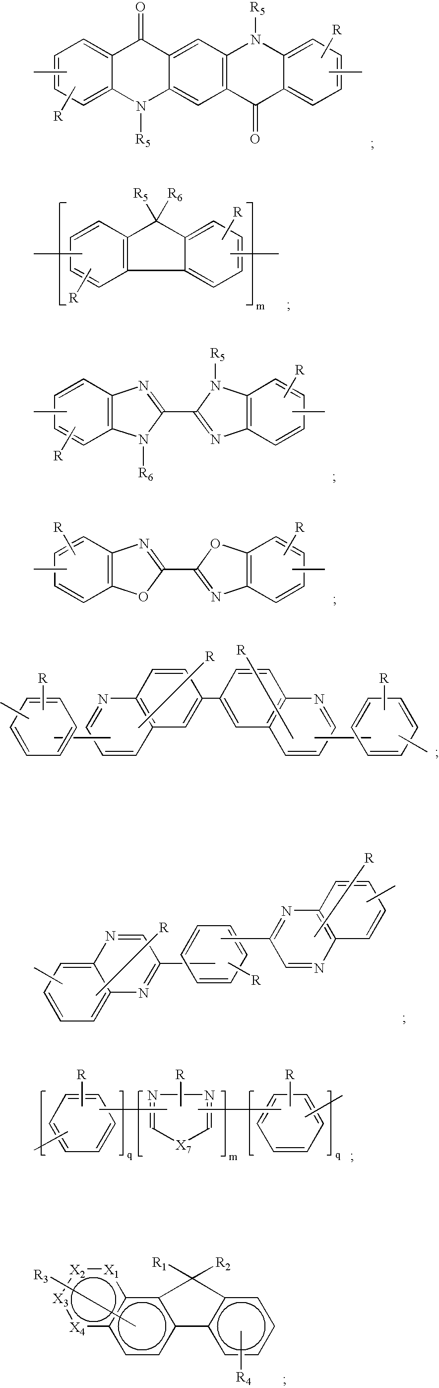

- wherein: X10 is an O atom or two cyano groups;

R1═R2=n-octyl, R7═H compound 2
R1═R2=2-ethylhexyl, R7=n-hexyl compound 3
R1=n-hexyl, R2=2-ethylhexyl, R7═

R1═R2=2-ethylhexyl, R7═H compound 6
R1=n-hexyl, R2=2-ethylhexyl, R7═H compound 7

R1=n-hexyl, R2=2-ethylhexyl, R7=2-ethylhexyl compound 9
R1=n-hexyl, R2=2-ethylhexyl, R7=2-ethylhexyloxy compound 10
R1═R2═R7=2-ethylhexyl compound 11

R1=n-hexyl, R2═R7=2-ethylhexyl compound 13
R1=n-hexyl, R2=2-ethylhexyl, R7=2-ethylhexyloxy compound 14
R1═R2═R7=2-ethylhexyl compound 15
R1═R2=2-ethylhexyl, R7═

R1=n-hexyl, R2═R7=2-ethylhexyl compound 18
R1=n-hexyl, R2=2-ethylhexyl, R7=2-ethylhexyloxy compound 19
R1═R2═R7=2-
R1═R2=2-ethylhexyl, R7=n-octyl compound 21

R1═R2=n-hexyl compound 23
R1═R2=2-ethylhexyl compound 24
R1═R2=phenyl compound 25
R1═R2=4-(bis(4-methylphenyl)amino)phenyl compound 26

R1═R2=4-(bis(4-methylphenyl)amino)phenyl compound 28
R1=2-ethylhexyl, R2=n-octyl compound 29

R1═R2═R7═R8=n-hexyl compound 31
R1═R7=n-hexyl, R2=2-ethylhexyl, R8═H compound 32

R1═R2═R7═R8=n-hexyl compound 34
R1═R7=n-hexyl, R2=2-ethylhexyl, R8═H compound 35
R1═R2═R7=4-(bis(4-methylphenyl)amino)phenyl, R8=n-hexyl compound 36

R1=n-hexyl, R2═R7=2-ethylhexyl compound 38
R1=n-hexyl, R2=2-ethylhexyl, R7=2-ethylhexyloxy compound 39
R1═R2=2-ethylhexyl, R7=4-(bis(4-methylphenyl)amino)
R1═H, R2=4-n-decylphenyl, R7=4-(bis(4-methylphenyl)amino)phenyl compound 41

R1=n-hexyl, R2=2-ethylhexyl, R7=2-ethylhexyloxy compound 43
R1═H, R2=4-n-decylphenyl, R7=4-(bis(4-methylphenyl)amino)phenyl compound 44
R1═H, R2=4-n-decylphenyl, R7=2-ethylhexyloxy compound 44

R1=n-hexyl, R2=2-ethylhexyl, R7=2-ethylhexyloxy, R8=diphenylamino compound 46
R1═H, R2=4-n-decylphenyl, R7═R8=4-(bis(4-methylphenyl)amino)phenyl compound 47
R1═H, R2=4-n-decylphenyl, R7=2-ethylhexyloxy, R8=4-(bis(4-methylphenyl)amino)phenyl compound 48

R1═R7=4-(bis(4-methylphenyl)amino)phenyl, R2═R8═H compound 50
R1═R2═R7═R8=4-n-decylphenyl compound 51

R1═R7=4-(bis(4-methylphenyl)amino)phenyl, R2═R8═H compound 53
R1═R2═R7═R8=4-n-decylphenyl compound 54
R1═R2═R7═R8=n-octyl compound 55

R1═R2=4-(bis(4-methylphenyl)amino)phenyl, R7═R8═H compound 57
R1═R2═R7═R8=4-n-decylphenyl compound 58

R1═R2=4-(bis(4-methylphenyl)amino)phenyl, R7═H, R8=n-
R1═R2═R8=4-n-decylphenyl, R7═CN compound 61

R1═R2═R8=4-(bis(4-methylphenyl)amino)phenyl, R7═H compound 63
R1═R2 4-n-decylphenyl, R7═CN, R8=n-hexyloxy compound 64

R1═R2=4-(bis(4-methylphenyl)amino)phenyl, R7=4-t-butylphenyl, R8=t-butyl compound 66
R1=hexyl, R2=4-n-decylphenyl, R7=2-ethylhexyl, R8=phenyl compound 67

R1═R2=4-(bis(4-methylphenyl)amino)phenyl, R7=phenyl, R8═H compound 69
R1=hexyl, R2=4-n-decylphenyl, R7=2-ethylhexyloxy, R8=phenyl compound 70

R =n-hexyl, R2=2-ethylhexyl, R7=2-ethylhexyloxy, R8=diphenylamino compound 72
R1═H, R2=4-n-decylphenyl, R7═R8=4-(bis(4-methylphenyl)amino)phenyl compound 73
R1═H, R2═R8=4-n-decylphenyl, R7=2-ethylhexyloxy compound 74

R1=n-hexyl, R2=2-ethylhexyl, R3═R4=2-ethylhexyloxy compound 72
R1═R2=4-(bis(4-methylphenyl)amino)phenyl, R3═R4=4-(t-butylphenyl) compound 73
R1═H, R2=4-n-decylphenyl, R3=2-ethylhexyloxy, R4=2-ethylhexyl compound 74

R1═R2═R7═R8=2-ethylhexyl compound 76
R1═R2=4-(bis(4-methylphenyl)amino)phenyl, R7═R8 H compound 77
R1═H, R2=4-n-decylphenyl, R7═R8=2-ethylhexyloxy compound 78

R1═R2=2-ethylhexyl, R7═R8=2-
R1═R2=4-(bis(4-methylphenyl)amino)phenyl, R7═R8=t-butyl compound 81

R1═H, R2=4-octylphenyl, R7═R8=2-ethylhexyl compound 83
R1═R2=2-ethylhexyl, R7=2-ethylhexyloxy, R8=3,7-dimethyloctyl compound 84

R1=3,7-dimethyloctyl, R2=4-octylphenyl compound 86
R1═R2=4-(bis(4-methylphenyl)amino)phenyl compound 87

R1═H, R2=4-octylphenyl, R7═R8=2-ethylhexyloxy compound 89
R1═R2=2-ethylhexyl, R7=4-t-butylphenyl, R8=3,7-dimethyloctyl compound 90

R1═H, R2=4-octylphenyl, R7═R8=2-ethylhexyl compound 92
R1═R2=2-ethylhexyl, R7=3,7-dimethyloctyloxy, R8=n-hexyl compound 93

R1═R2=2-ethylhexyl, R7=3,7-dimethyloctyloxy, R8=n-hexyl compound 95
R1═R2=2-ethylhexyl, R7=3,7-dimethyloctyloxy, R8=n-hexyl compound 96

R1=ethyl=R2 compound 98

R1═H, R2═R7=4-octylphenyl, R8=2-
R1═R2=2-ethylhexyl, R7=t-butyl, R8=
R1═R2=4-(bis(4-methylphenyl)amino)phenyl, R7═H, R8=phenyl compound 102

R1=n-hexyl, R2=4-octylphenyl, R7=t-butyl compound 104
R1═R2=4-(bis(4-methylphenyl)amino)phenyl, R7═

R1═H, R2═R7=4-octylphenyl, R8=2-
R1═R2=n-octyl, R7=diphenylamino, R8=t-butyl compound 108
R1═R2=4-(bis(4-methylphenyl)amino)phenyl, R7=t-butyl, R8=

R1═R2══R8=n-hexyl, R7=phenyl compound 111
R1═R7=n-hexyl, R2=(4-diphenylamino)pheny, R8=2-ethylhexyl compound 112
R1═H, R2=4-decylphenyl, R7=n-hexyl, R8=3,7-

R1═R7═H, R2═R8=4-octylphenyl compound 115
R1═R2=n-octyl, R7=(4-diphenylamino)phenyl, R8=2-ethylhexyl compound 116
R1═R2=4-(bis(4-methylphenyl)amino)phenyl, R7=n-decyl, R8=3,7-dimethyloctyl compound 117

R1═R7=n-hexyl, R2═R8=4-octylphenyl compound 119
R1═R2=n-octyl, R7=(4-diphenylamino)phenyl, R8=2-

R1═H, R2═R7=3,7-dimethyloctyl, R8=2-ethylhexyl compound 122
R1═R7=(4-diphenylamino)phenyl, R2=n-octyl, R8=n-hexyl compound 123
R1═R2=4-(bis(4-methylphenyl)amino)phenyl, R7=n-decyl, R8═H compound 124

R1═H, R2═R7=3,7-dimethyloctyl, R8=(4-diphenylamino)phenyl compound 126
R1═R7=4-(bis(4-methylphenyl)amino)phenyl, R2═R8 n-decyl compound 127

R1═H, R2=4-decylphenyl, R7═R8==3,7-dimethyloctyl, m=2, q=5 compound 129
R1═R7=4-(bis(4-methylphenyl)amino)phenyl, R2═R8=n-decyl, m=q=1 compound 130

R1═R2=4-decylphenyl, R7═H, R8=n-hexyl, m=1 compound 132
R1═R2=n-hexyl, R7═R8═H, m=11 compound 133
R1═R2=4-(bis(4-methylphenyl)amino)phenyl, R3=diphenylamino, R4═H, m=17 compound 134

R1═H, R2═R7=3,7-dimethyloctyl, R8=(4-diphenylamino)phenyl,m=2 compound 136
R1═R7=4-(bis(4-methylphenyl)amino)phenyl, R2═R8=n-decyl, m=3 compound 137

R1═H, R2═R7=3,7-dimethyloctyl, R8=(4-diphenylamino)phenyl compound 138
R1=4-(bis(4-methylphenyl)amino)phenyl, R2=n-decyl, R7=t-butyl, R8=n-hexyloxy compound 139

R1═H, R2═R7=3,7-dimethyloctyl, R8=(4-diphenylamino)phenyl compound 141
R1=4-(bis(4-methylphenyl)amino)phenyl, R2=n-decyl, R7=t-butyl, R8=n-hexyloxy compound 142
R1=4-(N-carbazole)phenyl, R2=n-decyl, R7=2-ethylhexyloxy, R8=n-hexyl compound 143
R1=4-(n-decyl)phenyl, R2═R7═R8═H compound 144

R1═R2=4-decylphenyl, R7═H, R8=n-hexyl, m=1 compound 146
R1═R7═R8═H, R2=4-decylphenyl, m=11 compound 147
R1═R2=4-(bis(4-methylphenyl)amino)phenyl, R7=diphenylamino, R8═H, m=17 compound 148

R1═R2=2-ethylhexyl, R7=n-hexyl, R8═CF3, X═C compound 150
R1═R7=4-decylphenyl, R2═H, R8=n-butyl, X═Si compound 151
R1═H, R2=4-(bis(4-methylphenyl)amino)phenyl, R7=diphenylamino, R8=n-hexyl, X═Si compound 152

R1═H, R2═R7=3,7-dimethyloctyl, R8=(4-diphenylamino)phenyl compound 154
R1=4-(bis(4-methylphenyl)amino)phenyl, R2=n-decyl, R7=t-butyl, R8=n-hexyloxy compound 155
R1=4-(N-carbazole)phenyl, R2=n-decyl, R7=2-ethylhexyloxy, R8=n-hexyl compound 156

R1═H, R2═R7=3,7-dimethyloctyl, R8=(4-diphenylamino)phenyl compound 158
R1=4-(bis(4-methylphenyl)amino)phenyl, R2=n-decyl, R7=t-butyl, R8=n-hexyloxy compound 159

R1═H, R2═R7=3,7-dimethyloctyl, R8=(4-diphenylamino)phenyl compound 161
R1=4-(bis(4-methylphenyl)amino)phenyl, R2=n-decyl, R7=t-butyl, R8=n-hexyloxy compound 162

R1=n-hexyl, R2═R7=3,7-dimethyloctyl, R8=(4-diphenylamino)phenyl compound 164
R1═R2=n-hexyl, R7═R8═H compound 165
R1=4-(bis(4-methylphenyl)amino)phenyl, R2=n-decyl, R7=t-butyl, R8=n-hexyloxy compound 166
R1═R2 n-hexyl, R7═R8=n-octyl compound 167
R1═R2=n-hexyl, R7═R8=n-hexyloxy compound 168

R1═H, R2═R7=3,7-dimethyloctyl, R8=(4-diphenylamino)phenyl compound 170
R1=4-(bis(4-methylphenyl)amino)phenyl, R2=n-decyl, R7═R8=n-hexyl compound 171

R1=n-hexyl, R2═R7=3,7-dimethyloctyl, R8=(4-diphenylamino)phenyl compound 173
R1═R2═R7═R8=n-hexyl compound 174
R1=4-(bis(4-methylphenyl)amino)phenyl, R2=n-decyl, R7═R8=n-octyl compound 175

R1═R7=n-hexyl, R2=3,7-dimethyloctyl, R8=(4-diphenylamino)phenyl compound 177
R1═R2═R7═R8=n-hexyl compound 178
R1=4-(bis(4-methylphenyl)amino)phenyl, R2=n-decyl, R7=methyl, R8=n-hexyl compound 179

R1═R9=n-hexyl, R2═R7═R10=3,7-dimethyloctyl, R8=(4-diphenylamino)phenyl compound 181
R1═R2═R9═R10=n-hexyl, R7=n-hexyloxy, R8═H compound 182
R1═R9=4-(bis(4-methylphenyl)amino)phenyl, R2=═R10=n-decyl, R7=t-butyl, R8=n-hexyloxy compound 183
R1═R2═R9═R10=n-hexyl, R7=n-hexyloxy, R8=n-octyl compound 184
R1═R2═R9═R10=n-hexyl, R7═R8=n-hexyloxy compound 185

R1═R2═R9═R10=n-hexyl, R7═R8=(4-diphenylamino)phenyl compound 187
R1═R2═R7═R8══R9═R10=n-hexyl compound 188
R1═R9=4-decylphenyl, R2═R10═H, R7═R8=n-hexyloxy compound 189

R1═H, R2═R7=3,7-dimethyloctyl, R8 (4-diphenylamino)phenyl compound 191
R1=4-(bis(4-methylphenyl)amino)phenyl, R2=n-decyl, R7═R8=n-hexyl compound 192

R1═R2=2-ethylhexyl, R7═R8=(4-diphenylamino)phenyl compound 194
R1═R2═R7═R8=n-hexyl compound 195
R1=4-decylphenyl, R2═H, R7═R8═CF3 compound 196

R1═R2=n-hexyl, R7═R8═H compound 198
R1=2-ethylhexyl, R2=n-hexyl, R7═R8═H compound 199
R1=n-hexyl, R2═R7=3,7-dimethyloctyl, R8=(4-diphenylamino)phenyl compound 200
R1=2-ethylhexyl, R2=n-hexyl, R7═R8=n-hexyloxy compound 201
R1=4-(bis(4-methylphenyl)amino)phenyl, R2=n-decyl, R7=t-butyl, R8=n-hexyloxy compound 202

R1=2-ethylhexyl, R2=n-hexyl, R7═R8═H compound 204
R1=n-hexyl, R2═R8=3,7-dimethyloctyl, R7=(4-diphenylamino)phenyl compound 205
R1═R2=n-hexyl, R7=t-butyl, R8═H compound 206
R1=4-(bis(4-methylphenyl)amino)phenyl, R2=n-decyl, R7=n-butyl, R8=n-hexyloxy compound 207

R1=2-ethylhexyl, R2=n-hexyl, R7═R8=n-butyl compound 209
R1=n-hexyl, R2=(4-diphenylamino)phenyl, R7═H, R8=3,7-dimethyloctyl compound 210
R1═R2=n-hexyl, R7═R8=4-(bis(4-methylphenyl)amino)phenyl compound 211

R1=2-ethylhexyl, R2=n-hexyl, R7=4-t-butylphenyl, R8═H compound 213
R1=n-hexyl, R2═R8=3,7-dimethyloctyl, R7=(4-diphenylamino)phenyl compound 214
R1═R2=n-hexyl, R7=2-ethylhexyl, R8═H compound 215

R1=2-ethylhexyl, R2=n-hexyl, R7=4-t-butylphenyl, R8═H compound 217
R1=n-hexyl, R2=3,7-dimethyloctyl, R7=(4-diphenylamino)pheny, R8=n-hexyloxy compound 218

R1=2-ethylhexyl, R2=n-hexyl, R7=4-t-butylphenyl, R8=n-hexyloxy compound 220
R1═R2=n-hexyl, R7=2-ethylhexyl, R8═H compound 221

R1═R2=2-ethylhexyl, R7═Rx =(4-diphenylamino)phenyl compound 223
R1═R2═R7═R8 n-hexyl compound 224
R1=4-decylphenyl, R2═H, R7═R8═CF3 compound 225

R1═R2=2-ethylhexyl, R7=4-t-butylphenyl, R8═CN compound 227
R1=4-decylphenyl, R2═H, R7═CF3, R8=phenyl compound 228

R1=2-ethylhexyl, R2=n-hexyl, R7═R8═H, R9=4-t-butylphenyl compound 230
R1═R2=n-hexyl, R7═H, R8=methoxy, R9=3,7-dimethyloctyloxy compound 231
R1=n-hexyl, R2═R8=3,7-dimethyloctyl, R7═H, R9=(4-diphenylamino)phenyl compound 232

R1═R2=n-hexyl, R7═R8═H, R9=2-ethylhexyl compound 234
R1=4-decylphenyl, R2═R8=3,7-dimethyloctyl, R7═H, R9=(4-diphenylamino)phenyl compound 235

R1═R2=n-hexyl, R7═R8═H, R9=2-ethylhexyl compound 237
R1=4-decylphenyl, R2═R8=3,7-dimethyloctyl, R7═H, R9=(4-diphenylamino)phenyl compound 238

R1═R2=n-hexyl, R7=phenyl, R8═CN compound 240
R1=4-decylphenyl, R2═R7=3,7-dimethyloctyl, R8=methylcompound 241

R1═R2=n-hexyl, R7=4-decylphenyl, R8=2-ethylhexyloxy compound 243
R1=(4-diaminophenyl)1phenyl, R2═R7=3,7-dimethyloctyl, R8═H compound 244

R1═R2=n-hexyl, R7=n-octyloxy, R8═CN compound 246
R1=4-decylphenyl, R2═R7=3,7-dimethyloctyl, R8═CN compound 247

R1═R2=n-hexyl, R7=phenyl compound 249
R1=4-decylphenyl, R2=n-octyl, R7═
R1=4-(diphenylamino)phenyl, R2=n-hexyl, R7=n-hexyloxy compound 251

R1═R2═R7═R8=n-octyl compound 253
R1═R7=4-decylphenyl, R2═R8=3,7-dimethyloctyl compound 254

R1═R2=n-hexyl, R7═H, R8=n-hexyloxy, R9=2-ethylhexyl compound 256
R1=4-decylphenyl, R2═R8=3,7-dimethyloctyl, R7═H, R9=(4-diphenylamino)phenyl compound 257

R1═R2=n-hexyl, R7=n-octyloxy, R8═CN compound 259
R1═R7=4-decylphenyl, R2=3,7-dimethyloctyl, R8═

R1═R7=n-hexyl, R2═R8=(4-diphenylamino)phenyl compound 262
R1=n-hexyl, R2=(4-diphenylamino)phenyl, R7═H, R8=4-decylphenyl compound 263

R1═R2=n-hexyl, R7=phenyl, R8═H compound 265
R1=4-decylphenyl, R2═R7=3,7-dimethyloctyl, R8=methoxy compound 266

R1═R7═R9=n-hexyl, R2═R8═R10=4-t-butylphenyl compound 268

R1═R7═H, R2═R8=4-t-butylphenyl compound 270
R1=4-(diphenylamino)phenyl, R2═R7=n-hexyl, R8=4-t-butylphenyl compound 271

R1=n-hexyl, R2═R7=2-ethylhexyl compound 273
R1═R2=2-ethylhexyl, R7=4-t-butylphenyl compound 274

R1=2-ethylhexyl, R2=n-hexyl, R7=4-t-butylphenyl, R8═H compound 276
R1=n-hexyl, R2═R8=3,7-dimethyloctyl, R7=(4-diphenylamino)phenyl compound 277
R1=phenyl, R2=4-decylphenyl, R7=2-ethylhexyl, R8═H compound 278

R1═R2=n-hexyl, R7=t-butyl, R8═H compound 280
R1═R2═R7═R8=n-hexyl compound 281
R1=4-decylphenyl, R2=phenyl, R7=t-butyl, R8═H compound 282

R1═R2=n-hexyl, R7=n-hexyloxy, R8═H compound 284
R1═R2═R7═R8=n-hexyl compound 285
R1═R2=n-hexyl, R7=n-octyl, R8═H compound 286
R1=4-decylphenyl, R2=phenyl, R7=t-butyl, R8═H compound 287

R1═R2=n-hexyl, R7=t-butyl, R8═H compound 289
R1═R2═R7═R8=n-hexyl compound 290
R1=4-decylphenyl, R2=phenyl, R7=t-butyl, R8═H compound 291

R1=2-ethylhexyl, R2=n-hexyl, R7=4-t-butylphenyl, R8═R9═H compound 293
R1═R2═R9=3,7-dimethyloctyl, R7═R8=(4-diphenylamino)phenyl compound 294
R1=phenyl, R2=4-decylphenyl, R7=2-ethylhexyl, R8═H, R9=di(4-methylphenyl)amino compound 295
wherein Q1 and Q2 are independently selected aromatic tertiary amine moieties and G is a linking group such as an arylene, cycloalkylene, or alkylene group of a carbon to carbon bond. In one embodiment, at least one of Q1 or Q2 contains a polycyclic fused ring structure, e.g., a naphthalene. When G is an aryl group, it is conveniently a phenylene, biphenylene, or naphthalene moiety.

wherein:
-
- R15 and R16 each independently represents a hydrogen atom, an aryl group, or an alkyl group or R1 and R2 together represent the atoms completing a cycloalkyl group; and
- R17 and R18 each independently represents an aryl group, which is in turn substituted with a diaryl substituted amino group, as indicated by structural formula (C):

wherein R19 and R20 are independently selected aryl groups. In one embodiment, at least one of R19 or R20 contains a polycyclic fused ring structure, e.g., a naphthalene.

wherein
-
- each Ar3 is an independently selected arylene group, such as a phenylene or anthracene moiety,
- t is an integer of from 1 to 4, and
- Ar4, R21, R22, and R23 are independently selected aryl groups.
-
- 1,1-Bis(4-di-p-tolylaminophenyl)cyclohexane
- 1,1-Bis(4-di-p-tolylaminophenyl)-4-phenylcyclohexane
- 4,4′-Bis(diphenylamino)quadriphenyl
- Bis(4-dimethylamino-2-methylphenyl)-phenylmethane
- N,N,N-Tri(p-tolyl)amine
- 4-(di-p-tolylamino)-4′-[4(di-p-tolylamino)-styryl]stilbene
- N,N,N′,N′-Tetra-p-tolyl-4-4′-diaminobiphenyl
- N,N,N′,N′-Tetraphenyl-4,4′-diaminobiphenyl
- N,N,N′,N′-tetra-1-naphthyl-4,4′-diaminobiphenyl
- N,N,N′,N′-tetra-2-naphthyl-4,4′-diaminobiphenyl
- N-Phenylcarbazole
- 4,4′-Bis[N-(1-naphthyl)-N-phenylamino]biphenyl
- 4,4′-Bis[N-(1-naphthyl)-N-(2-naphthyl)amino]biphenyl
- 4,4″-Bis[N-(1-naphthyl)-N-phenylamino]p-terphenyl
- 4,4′-Bis[N-(2-naphthyl)-N-phenylamino]biphenyl
- 4,4′-Bis[N-(3-acenaphthenyl)-N-phenylamino]biphenyl
- 1,5-Bis[N-(1-naphthyl)-N-phenylamino]naphthalene
- 4,4′-Bis[N-(9-anthryl)-N-phenylamino]biphenyl
- 4,4″-Bis[N-(1-anthryl)-N-phenylamino]-p-terphenyl
- 4,4′-Bis[N-(2-phenanthryl)-N-phenylamino]biphenyl
- 4,4′-Bis[N-(8-fluoranthenyl)-N-phenylamino]biphenyl
- 4,4′-Bis[N-(2-pyrenyl)-N-phenylamino]biphenyl
- 4,4′-Bis[N-(2-naphthacenyl)-N-phenylamino]biphenyl
- 4,4′-Bis[N-(2-perylenyl)-N-phenylamino]biphenyl
- 4,4′-Bis[N-(1-coronenyl)-N-phenylamino]biphenyl
- 2,6-Bis(di-p-tolylamino)naphthalene
- 2,6-Bis[di-(1-naphthyl)amino]naphthalene
- 2,6-Bis[N-(1-naphthyl)-N-(2-naphthyl)amino]naphthalene
- N,N,N′,N′-Tetra(2-naphthyl)-4,4″-diamino-p-terphenyl
- 4,4′-Bis {N-phenyl-N-[4-(1-naphthyl)-phenyl]amino}biphenyl
- 4,4′-Bis[N-phenyl-N-(2-pyrenyl)amino]biphenyl
- 2,6-Bis[N,N-di(2-naphthyl)amine]fluorene
- 1,5-Bis[N-(1-naphthyl)-N-phenylamino]naphthalene
- 4,4′,4″-tris[(3-methylphenyl)phenylamino]triphenylamine

wherein:
-
- CO-1: Aluminum trisoxine [alias, tris(8-quinolinolato)aluminum(III)]
- CO-2: Magnesium bisoxine [alias, bis(8-quinolinolato)magnesium(II)]
- CO-3: Bis[benzo {f}-8-quinolinolato]zinc (II)
- CO-4: Bis(2-methyl-8-quinolinolato)aluminum(III)-μ-oxo-bis(2-methyl-8-quinolinolato) aluminum(III)
- CO-5: Indium trisoxine [alias, tris(8-quinolinolato)indium]
- CO-6: Aluminum tris(5-methyloxine) [alias, tris(5-methyl-8-quinolinolato) aluminum(III)]
- CO-7: Lithium oxine [alias, (8-quinolinolato)lithium(I)]
- CO-8: Gallium oxine [alias, tris(8-quinolinolato)gallium(III)]
- CO-9: Zirconium oxine [alias, tetra(8-quinolinolato)zirconium(IV)]

wherein: R24, R25, R26, R27, R28, and R29 represent one or more substituents on each ring where each substituent is individually selected from the following groups:

wherein:


Electron-Transporting Layer (ETL):


-
- a) An indium-tin-oxide (ITO) coated glass substrate was sequentially ultra-sonicated in a commercial detergent, rinsed with deionized water, degreased in toluene vapor and exposed to ultraviolet light and ozone for a few minutes.
- b) An aqueous solution of PEDOT (1.3% in water, Baytron P Trial Product Al 4083 from H. C. Stark) was spin-coated onto ITO under a controlled spinning speed to obtain thickness of 500 Angstroms. The coating was baked in an oven at 110° C. for 10 min.
- c) A toluene solution of a compound (300 mg in 30 mL of solvent) was filtered through a 0.2 μm Teflon filter. The solution was then spin-coated onto PEDOT under a controlled spinning speed. The thickness of the film was between 500-700 Angstroms.
- d) On the top of the organic thin film was deposited a cathode layer consisting of 15 angstroms of a CsF salt, followed by a 2000 angstroms of a 10:1 atomic ratio of Mg and Ag.
| TABLE 1 |
| Characterization of polymers according to Examples. |
| UVb | |||||||
| Com- | Td | Tg | (λmax | PLc | EL | ||
| pound | Mw a | PDI | (° C.) | (° C.) | nm) | (λmax nm) | (λmax nm) |
| 165 | 16300 | 1.70 | 428 | 183 | 380 | 420 (382) | 452 |
| 167 | 23200 | 2.30 | 441 | 50 | 342 | 396 (342) | 412 |
| 168 | 29200 | 1.97 | 418 | 86 | 376 | 420 (380) | 452 |
| 174 | 34400 | 2.01 | 429 | 138 | 392 | 424 (394) | 456 |
| 190 | 7000 | 1.85 | 426 | 137 | 378 | 424 (394) | 476 |
| 221 | 14100 | 1.80 | 430 | 190 | 362 | 410 (364) | 440 |
| 206 | 38200 | 2.15 | 358 | NOf | 392 | 432 (394) | 468 |
| 231 | 39300 | 2.62 | 405 | 123 | 428 | 522 (430) | 520 |
| 215 | 13100 | 1.65 | 433 | 140 | 388 | 426 (384) | 456 |
| 133 | 29000 | 2.27 | 420 | 72 | 358 | 422 (360) | 468 |
| 280 | 976 | 1.21 | 278 | 70 | NAd | NA | NA |
| 282 | 4920 | 1.57 | 454 | 182 | 394e | 448 (396)e | 488 |
| 278 | 2550 | 1.35 | 449 | 128 | 380e | 428 (382)e | NA |
| 284 | 1860 | 1.28 | 236 | 54 | 368e | 430 (370)e | NA |
| 198 | 7990 | 2.52 | 436 | 174 | 384 | 448 (386) | 452 |
| 199 | 6890 | 1.50 | 421 | NO | 384 | 424 (386) | NA |
| 201 | 14100 | 1.68 | 405 | 76 | 388 | 450 (378) | 460 |
| 273 | 5190 | 1.38 | 409 | 175 | 364 | 442 (366) | 468 |
| aweight average molecular weight, determined by size exclusion chromatography in THF using polystyrene standard. | |||||||
| bas solid state thin film | |||||||
| cas solid state thin film, the number in the parenthesis is the excitation wavelength | |||||||
| dnot available | |||||||
| ein toluene solution. | |||||||
| fnot observed. | |||||||
- 101 substrate
- 103 anode
- 105 hole-injecting layer
- 107 hole transporting layer
- 109 light emitting layer
- 111 electron-transporting layer
- 113 cathode
- 250 voltage-current source
- 260 electrical conductors
Claims (18)


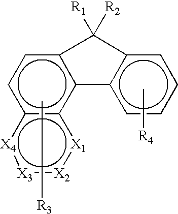


Priority Applications (7)
| Application Number | Priority Date | Filing Date | Title |
|---|---|---|---|
| US10/334,359 US6849348B2 (en) | 2002-12-31 | 2002-12-31 | Complex fluorene-containing compounds |
| TW092130270A TW200416269A (en) | 2002-12-31 | 2003-10-30 | Complex fluorene-containing compounds |
| KR1020057012260A KR101032696B1 (en) | 2002-12-31 | 2003-12-19 | Complex fluorene-containing compounds and electroluminescent devices |
| JP2004565609A JP4897222B2 (en) | 2002-12-31 | 2003-12-19 | Composite fluorene-containing compound and electroluminescent device |
| PCT/US2003/040731 WO2004061048A1 (en) | 2002-12-31 | 2003-12-19 | Complex fluorene-containing compounds and electroluminescent devices |
| CNB2003801100524A CN100360636C (en) | 2002-12-31 | 2003-12-19 | Complex fluorene-containing compounds and electroluminescent devices |
| US10/875,011 US7348071B2 (en) | 2002-12-31 | 2004-06-23 | Complex fluorene-containing compounds and use |
Applications Claiming Priority (1)
| Application Number | Priority Date | Filing Date | Title |
|---|---|---|---|
| US10/334,359 US6849348B2 (en) | 2002-12-31 | 2002-12-31 | Complex fluorene-containing compounds |
Related Parent Applications (1)
| Application Number | Title | Priority Date | Filing Date |
|---|---|---|---|
| US10/335,441 Continuation-In-Part US20040131881A1 (en) | 2002-12-31 | 2002-12-31 | Complex fluorene-containing compounds for use in OLED devices |
Related Child Applications (1)
| Application Number | Title | Priority Date | Filing Date |
|---|---|---|---|
| US10/875,011 Continuation-In-Part US7348071B2 (en) | 2002-12-31 | 2004-06-23 | Complex fluorene-containing compounds and use |
Publications (2)
| Publication Number | Publication Date |
|---|---|
| US20040131880A1 US20040131880A1 (en) | 2004-07-08 |
| US6849348B2 true US6849348B2 (en) | 2005-02-01 |
Family
ID=32680801
Family Applications (2)
| Application Number | Title | Priority Date | Filing Date |
|---|---|---|---|
| US10/334,359 Expired - Lifetime US6849348B2 (en) | 2002-12-31 | 2002-12-31 | Complex fluorene-containing compounds |
| US10/875,011 Expired - Lifetime US7348071B2 (en) | 2002-12-31 | 2004-06-23 | Complex fluorene-containing compounds and use |
Family Applications After (1)
| Application Number | Title | Priority Date | Filing Date |
|---|---|---|---|
| US10/875,011 Expired - Lifetime US7348071B2 (en) | 2002-12-31 | 2004-06-23 | Complex fluorene-containing compounds and use |
Country Status (6)
| Country | Link |
|---|---|
| US (2) | US6849348B2 (en) |
| JP (1) | JP4897222B2 (en) |
| KR (1) | KR101032696B1 (en) |
| CN (1) | CN100360636C (en) |
| TW (1) | TW200416269A (en) |
| WO (1) | WO2004061048A1 (en) |
Cited By (18)
| Publication number | Priority date | Publication date | Assignee | Title |
|---|---|---|---|---|
| US20040198042A1 (en) * | 2003-04-05 | 2004-10-07 | Rohm And Haas Electronic Materials, L.L.C. | Preparation of Group IVA and Group VIA compounds |
| US20040241496A1 (en) * | 2002-12-31 | 2004-12-02 | Eastman Kodak Company | Complex fluorene-containing compounds and use |
| US20050202279A1 (en) * | 2002-12-31 | 2005-09-15 | Eastman Kodak Company | Complex fluorene-containing compounds for use in OLED devices |
| US20050208332A1 (en) * | 2004-03-17 | 2005-09-22 | Byung-Doo Chin | White-light-emitting organic electroluminescent device and organic electroluminescent display having the same |
| US20070029556A1 (en) * | 2005-08-08 | 2007-02-08 | Osram Opto Semiconductors Gmbh | Solution processed crosslinkable hole injection and hole transport polymers for OLEDs |
| US20070187673A1 (en) * | 2004-02-25 | 2007-08-16 | Eastman Kodak Comany | Electroluminescent devices having pendant naphthylanthracene-based polymers |
| US20080160348A1 (en) * | 2006-12-29 | 2008-07-03 | Eric Maurice Smith | Benzofluorenes for luminescent applications |
| US20080160347A1 (en) * | 2006-10-05 | 2008-07-03 | Guofang Wang | Benzofluorene compound, emission materials and organic electroluminescent device |
| KR20080087675A (en) * | 2007-03-27 | 2008-10-01 | 세이코 엡슨 가부시키가이샤 | Organic electroluminescent device |
| US20080278072A1 (en) * | 2007-04-30 | 2008-11-13 | Lg Chem, Ltd. | Organic light emitting device and method of producing the same |
| US20090184312A1 (en) * | 2006-04-13 | 2009-07-23 | Tosoh Corporation | Benzofluorene compound and use thereof |
| US20090189518A1 (en) * | 2007-11-27 | 2009-07-30 | Canon Kabushiki Kaisha | Fused polycyclic compounds and organic light-emitting device using the same |
| US20110204354A1 (en) * | 2008-11-06 | 2011-08-25 | Canon Kabushiki Kaisha | Indenopyrene compound and organic light-emitting device using the compound |
| US8846214B2 (en) | 2009-06-05 | 2014-09-30 | Tosoh Corporation | Amine derivative and organic electroluminescent element |
| US9748492B2 (en) | 2012-11-02 | 2017-08-29 | Idemitsu Kosan Co., Ltd. | Organic electroluminescent device |
| KR20190010419A (en) | 2017-07-21 | 2019-01-30 | 롬엔드하스전자재료코리아유한회사 | Organic Electroluminescent Compound and Organic Electroluminescent Device Comprising the Same |
| US10875825B2 (en) | 2017-08-18 | 2020-12-29 | Samsung Display Co., Lid. | Amine-based compound and organic light-emitting device including the same |
| US11744146B2 (en) | 2017-02-03 | 2023-08-29 | Samsung Display Co., Ltd. | Amine-based compound and organic light-emitting device including the same |
Families Citing this family (73)
| Publication number | Priority date | Publication date | Assignee | Title |
|---|---|---|---|---|
| TW201235442A (en) * | 2003-12-12 | 2012-09-01 | Sumitomo Chemical Co | Polymer and light-emitting element using said polymer |
| JP4792738B2 (en) * | 2003-12-12 | 2011-10-12 | 住友化学株式会社 | Polymer compound and polymer light emitting device using the same |
| JP2006128624A (en) * | 2004-09-29 | 2006-05-18 | Canon Inc | Light emitting element |
| US20060094859A1 (en) * | 2004-11-03 | 2006-05-04 | Marrocco Matthew L Iii | Class of bridged biphenylene polymers |
| JP4904752B2 (en) * | 2004-11-24 | 2012-03-28 | 住友化学株式会社 | Polymer compound and polymer light emitting device using the same |
| US7800103B2 (en) * | 2004-12-02 | 2010-09-21 | Konica Minolta Holdings, Inc. | Organic thin film transistor material, organic thin film transistor, field-effect transistor, switching element, organic semiconductor material and organic semiconductor film |
| WO2006070911A1 (en) * | 2004-12-27 | 2006-07-06 | Sumitomo Chemical Company, Limited | Polymer and polymeric luminescent element employing the same |
| JP4904805B2 (en) * | 2004-12-27 | 2012-03-28 | 住友化学株式会社 | Polymer compound and polymer light emitting device using the same |
| JP5256568B2 (en) * | 2004-12-28 | 2013-08-07 | 住友化学株式会社 | Polymer compound and polymer light emitting device using the same |
| JP4896411B2 (en) * | 2005-02-18 | 2012-03-14 | 住友化学株式会社 | Polymer compound and polymer light emitting device using the same |
| JP4724440B2 (en) * | 2005-03-04 | 2011-07-13 | 住友化学株式会社 | Polymer compound and polymer light emitting device using the same |
| GB0507684D0 (en) * | 2005-04-15 | 2005-05-25 | Cambridge Display Tech Ltd | Pulsed driven displays |
| DE102005023437A1 (en) * | 2005-05-20 | 2006-11-30 | Merck Patent Gmbh | Connections for organic electronic devices |
| JP5457619B2 (en) * | 2005-06-10 | 2014-04-02 | 住友化学株式会社 | Polyarylene |
| TWI415920B (en) * | 2005-08-12 | 2013-11-21 | Sumitomo Chemical Co | High molecular weight material and element using such material |
| ATE509055T1 (en) * | 2005-08-16 | 2011-05-15 | Merck Patent Gmbh | METHOD FOR POLYMERIZING THIOPHEN OR SELENOPHENE DERIVATIVES |
| JP2007119763A (en) * | 2005-09-29 | 2007-05-17 | Sumitomo Chemical Co Ltd | Polymeric material and polymeric light emitting device |
| JP5162888B2 (en) * | 2005-12-02 | 2013-03-13 | 住友化学株式会社 | Polymer compound and polymer light emitting device using the same |
| GB2434915A (en) * | 2006-02-03 | 2007-08-08 | Cdt Oxford Ltd | Phosphoescent OLED for full colour display |
| JP5145717B2 (en) * | 2006-04-13 | 2013-02-20 | 東ソー株式会社 | Benzofluorene compounds and uses thereof |
| DE102006025846A1 (en) * | 2006-06-02 | 2007-12-06 | Merck Patent Gmbh | New materials for organic electroluminescent devices |
| DE102006031990A1 (en) * | 2006-07-11 | 2008-01-17 | Merck Patent Gmbh | New materials for organic electroluminescent devices |
| US7547757B2 (en) * | 2006-08-01 | 2009-06-16 | Headwaters Technology Innovation, Llc | Methods for manufacturing aryl-aryl coupled polymers |
| US7687601B2 (en) * | 2006-10-03 | 2010-03-30 | Headwaters Technology Innovation, Llc | Methods for purifying polymers using solid scavengers |
| JP5023683B2 (en) * | 2006-12-12 | 2012-09-12 | 東ソー株式会社 | Process for producing benzofluorene derivative and intermediate thereof |
| JP5439711B2 (en) * | 2007-01-26 | 2014-03-12 | 東ソー株式会社 | Benzofluorene compounds and uses thereof |
| JP5163853B2 (en) * | 2007-03-22 | 2013-03-13 | 東ソー株式会社 | Organic compounds and their uses |
| JP5369384B2 (en) * | 2007-03-29 | 2013-12-18 | 住友化学株式会社 | Organic photoelectric conversion device and polymer useful for production thereof |
| US20080283827A1 (en) * | 2007-05-15 | 2008-11-20 | Shiying Zheng | Fused-fluorene-containing materials as semiconductor materials for thin film transistors |
| JP5374833B2 (en) * | 2007-05-16 | 2013-12-25 | 東ソー株式会社 | Organic electroluminescent material and organic electroluminescent device using the same |
| JP5104074B2 (en) * | 2007-07-03 | 2012-12-19 | 住友化学株式会社 | Polymer and organic photoelectric conversion element using the same |
| JP5205858B2 (en) * | 2007-08-09 | 2013-06-05 | 東ソー株式会社 | Novel benzo [c] fluorene derivatives and uses thereof |
| JP5205859B2 (en) * | 2007-08-09 | 2013-06-05 | 東ソー株式会社 | Novel benzo [c] fluorene derivatives and uses thereof |
| JP2009149846A (en) * | 2007-11-29 | 2009-07-09 | Sumitomo Chemical Co Ltd | Composition containing amine compound and acceptor compound |
| JP5217476B2 (en) * | 2008-02-08 | 2013-06-19 | Jnc株式会社 | Benzofluorene compound, light emitting layer material and organic electroluminescent device using the compound |
| DE102008018670A1 (en) * | 2008-04-14 | 2009-10-15 | Merck Patent Gmbh | New materials for organic electroluminescent devices |
| JP5408902B2 (en) * | 2008-05-15 | 2014-02-05 | キヤノン株式会社 | Dibenzo [c, g] fluorene compound and organic light emitting device using the same |
| US8431249B2 (en) | 2008-11-06 | 2013-04-30 | Canon Kabushiki Kaisha | Dibenzo[C,G]fluorene compound and organic light-emitting device using same |
| US8174000B2 (en) * | 2009-02-11 | 2012-05-08 | Universal Display Corporation | Liquid compositions for inkjet printing of organic layers or other uses |
| KR101427605B1 (en) * | 2009-03-31 | 2014-08-07 | 롬엔드하스전자재료코리아유한회사 | Novel organic electroluminescent compounds and organic electroluminescent device using the same |
| KR20100109293A (en) * | 2009-03-31 | 2010-10-08 | 다우어드밴스드디스플레이머티리얼 유한회사 | Novel organic electroluminescent compounds and organic electroluminescent device using the same |
| WO2010135248A1 (en) | 2009-05-18 | 2010-11-25 | The Regents Of The University Of California | Electronically conductive polymer binder for lithium-ion battery electrode |
| KR20100137198A (en) * | 2009-06-22 | 2010-12-30 | 다우어드밴스드디스플레이머티리얼 유한회사 | Novel organic electroluminescent compounds and organic electroluminescent device using the same |
| KR101202347B1 (en) * | 2009-10-09 | 2012-11-16 | 삼성디스플레이 주식회사 | A condensed-cyclic compound and an organic light emitting diode employing an organic layer comprising the same |
| KR20110057400A (en) * | 2009-11-24 | 2011-06-01 | 덕산하이메탈(주) | Chemiclal based on indenoflurorene core and organic electroric element using the same, terminal thererof |
| CN102666549A (en) * | 2009-12-14 | 2012-09-12 | 出光兴产株式会社 | Polycyclic fused ring compound and organic thin film transistor using same |
| JPWO2011074231A1 (en) * | 2009-12-14 | 2013-04-25 | 出光興産株式会社 | Polycyclic fused ring compound and organic thin film transistor using the same |
| KR101144356B1 (en) * | 2009-12-18 | 2012-05-11 | 덕산하이메탈(주) | Chemiclal based on indenoflurorene core and organic electroric element using the same, terminal thererof |
| DE102010020567A1 (en) * | 2010-05-14 | 2011-11-17 | Merck Patent Gmbh | metal complexes |
| WO2011153105A1 (en) * | 2010-06-02 | 2011-12-08 | The Regents Of The University Of California | Si composite electrode with li metal doping for advanced lithium-ion battery |
| JP2011038103A (en) * | 2010-08-26 | 2011-02-24 | Sumitomo Chemical Co Ltd | Polymer compound and polymer light-emitting element using the same |
| KR101957902B1 (en) * | 2011-04-13 | 2019-03-14 | 에스에프씨 주식회사 | New compounds and organic light-emitting diode including the same |
| JP5780132B2 (en) | 2011-05-19 | 2015-09-16 | Jnc株式会社 | Benzofluorene compound, light emitting layer material and organic electroluminescent device using the compound |
| JP5973705B2 (en) | 2011-06-16 | 2016-08-23 | ユー・ディー・シー アイルランド リミテッド | Organic electroluminescent device, luminescent material for organic electroluminescent device, and light emitting device, display device and lighting device using the device |
| JP5982966B2 (en) | 2011-08-17 | 2016-08-31 | Jnc株式会社 | Benzofluorene compound, light emitting layer material and organic electroluminescent device using the compound |
| JP5890980B2 (en) | 2011-08-18 | 2016-03-22 | ユー・ディー・シー アイルランド リミテッド | ORGANIC ELECTROLUMINESCENT ELEMENT, COMPOUND FOR ORGANIC ELECTROLUMINESCENT ELEMENT, AND LIGHT EMITTING DEVICE, DISPLAY DEVICE AND LIGHTING DEVICE USING THE ELEMENT |
| JP6063114B2 (en) | 2011-08-18 | 2017-01-18 | ユー・ディー・シー アイルランド リミテッド | ORGANIC ELECTROLUMINESCENT ELEMENT, ELEMENT MATERIAL, AND LIGHT EMITTING DEVICE, DISPLAY DEVICE AND LIGHTING DEVICE USING THE ELEMENT |
| JP5952543B2 (en) | 2011-08-18 | 2016-07-13 | ユー・ディー・シー アイルランド リミテッド | ORGANIC ELECTROLUMINESCENT ELEMENT, COMPOUND FOR ORGANIC ELECTROLUMINESCENT ELEMENT, AND LIGHT EMITTING DEVICE, DISPLAY DEVICE AND LIGHTING DEVICE USING THE ELEMENT |
| JP2013118349A (en) * | 2011-11-02 | 2013-06-13 | Udc Ireland Ltd | Organic electroluminescent element, material for organic electroluminescent element, and light emitting device, display device and illumination device which employ said organic electroluminescent element |
| TWI570095B (en) | 2011-11-04 | 2017-02-11 | 捷恩智股份有限公司 | Benzofluorene compound, material for luminescent layer using the compound, and organic electroluminescent device |
| JP6021389B2 (en) * | 2012-04-05 | 2016-11-09 | キヤノン株式会社 | Organic light emitting device |
| US9750758B2 (en) | 2012-06-25 | 2017-09-05 | Thomas Jefferson University | Compositions and methods for treating cancer with aberrant lipogenic signaling |
| TWI588238B (en) * | 2012-10-26 | 2017-06-21 | 捷恩智股份有限公司 | Benzofluorene compound, material for light emitting layer using the compound, organic electroluminescence element, display device and lighting device |
| WO2014106522A1 (en) | 2013-01-03 | 2014-07-10 | Merck Patent Gmbh | Materials for electronic devices |
| KR101326085B1 (en) * | 2013-01-08 | 2013-11-07 | 덕산하이메탈(주) | Chemiclal based on indenoflurorene core and organic electroric element using the same, terminal thererof |
| KR102137472B1 (en) * | 2013-02-08 | 2020-07-27 | 삼성디스플레이 주식회사 | Organic light emitting diode comprising the same |
| US20160181542A1 (en) | 2013-09-06 | 2016-06-23 | Idemitsu Kosan Co., Ltd. | Anthracene derivative and organic electroluminescent element using same |
| JP6346187B2 (en) | 2013-09-20 | 2018-06-20 | 出光興産株式会社 | ORGANIC ELECTROLUMINESCENT ELEMENT AND ELECTRONIC DEVICE |
| WO2015163206A1 (en) * | 2014-04-21 | 2015-10-29 | 住友化学株式会社 | Composition and polymer compound, and organic semiconductor element containing said composition and said polymer compound |
| KR101900370B1 (en) | 2015-05-13 | 2018-09-19 | 삼성에스디아이 주식회사 | Compound for ORGANIC OPTOELECTRIC DEVICE, ORGANIC OPTOELECTRIC DEVICE AND DISPLAY DEVICE |
| EP3334731B1 (en) | 2015-08-14 | 2021-03-03 | Merck Patent GmbH | Phenoxazine derivatives for organic electroluminescent devices |
| CN107573925B (en) * | 2016-07-05 | 2020-02-21 | 上海和辉光电有限公司 | Organic electroluminescent compound |
| US10232360B1 (en) * | 2017-09-12 | 2019-03-19 | Chevron Phillips Chemical Company, Lp | Use of organic dopants to enhance acetylene hydrogenation catalysts |
Citations (4)
| Publication number | Priority date | Publication date | Assignee | Title |
|---|---|---|---|---|
| US6358633B1 (en) | 1997-05-15 | 2002-03-19 | Sanyo Electric Co., Ltd. | Organic electroluminescence element |
| US6479662B2 (en) * | 1998-12-01 | 2002-11-12 | Board Of Regents, The University Of Texas System | Antitumor dibenzofluorene derivatives |
| US20030143422A1 (en) * | 2001-12-12 | 2003-07-31 | Chen Jian Ping | [5]-helicene and dibenzofluorene materials for use in organic light emitting devices |
| US20040062930A1 (en) * | 2002-09-25 | 2004-04-01 | 3M Innovative Properties Company | Electroactive polymers |
Family Cites Families (14)
| Publication number | Priority date | Publication date | Assignee | Title |
|---|---|---|---|---|
| WO1997033323A1 (en) * | 1996-03-04 | 1997-09-12 | Uniax Corporation | Polyfluorenes as materials for photoluminescence and electroluminescence |
| CA2214935A1 (en) * | 1996-09-26 | 1998-03-26 | Henry Uhlman Bryant | Benzofluorene compounds, intermediates, compositions, and methods |
| CA2215856A1 (en) * | 1996-09-26 | 1998-03-26 | Eli Lilly And Company | Dihydrobenzofluorene compounds, intermediates, compositions, and methods |
| US6309763B1 (en) * | 1997-05-21 | 2001-10-30 | The Dow Chemical Company | Fluorene-containing polymers and electroluminescent devices therefrom |
| TW460490B (en) * | 1999-05-13 | 2001-10-21 | Nat Science Council | Electroluminiscent conjugated polymers modified with high eletronegative heterocyclic moieties and their applications in polymeric light emitting diodes |
| DE60130748T2 (en) * | 2000-03-27 | 2008-07-17 | N.V. Organon | Non-steroidal tetracyclic compounds for estrogen-related treatments |
| EP1138746B2 (en) * | 2000-03-31 | 2014-01-01 | Sumitomo Chemical Company, Limited | Polymeric fluorescent substance, production method therof, and polymer light-emitting device using the same |
| JP5034140B2 (en) * | 2000-03-31 | 2012-09-26 | 住友化学株式会社 | Polymer phosphor, method for producing the same, and polymer light-emitting device using the same |
| EP1149827B1 (en) * | 2000-04-26 | 2003-12-10 | Sony International (Europe) GmbH | End-capped polyfluorenes, films and devices based thereon |
| KR100889514B1 (en) * | 2000-06-12 | 2009-03-19 | 맥스뎀인코포레이티드 | Polymer matrix electroluminescent materials and devices |
| TW200304371A (en) * | 2002-02-22 | 2003-10-01 | Akzo Nobel Nv | Substituted 10-ary1-11H-benzo [b] fluorenes and 7-ary1-5, 6-dihydro-benz [a] anthracenes for selective effects on estrogen receptors |
| TWI314947B (en) * | 2002-04-24 | 2009-09-21 | Eastman Kodak Compan | Organic light emitting diode devices with improved operational stability |
| US20040131881A1 (en) * | 2002-12-31 | 2004-07-08 | Eastman Kodak Company | Complex fluorene-containing compounds for use in OLED devices |
| US6849348B2 (en) * | 2002-12-31 | 2005-02-01 | Eastman Kodak Company | Complex fluorene-containing compounds |
-
2002
- 2002-12-31 US US10/334,359 patent/US6849348B2/en not_active Expired - Lifetime
-
2003
- 2003-10-30 TW TW092130270A patent/TW200416269A/en unknown
- 2003-12-19 CN CNB2003801100524A patent/CN100360636C/en not_active Expired - Lifetime
- 2003-12-19 KR KR1020057012260A patent/KR101032696B1/en active IP Right Grant
- 2003-12-19 JP JP2004565609A patent/JP4897222B2/en not_active Expired - Lifetime
- 2003-12-19 WO PCT/US2003/040731 patent/WO2004061048A1/en active Application Filing
-
2004
- 2004-06-23 US US10/875,011 patent/US7348071B2/en not_active Expired - Lifetime
Patent Citations (4)
| Publication number | Priority date | Publication date | Assignee | Title |
|---|---|---|---|---|
| US6358633B1 (en) | 1997-05-15 | 2002-03-19 | Sanyo Electric Co., Ltd. | Organic electroluminescence element |
| US6479662B2 (en) * | 1998-12-01 | 2002-11-12 | Board Of Regents, The University Of Texas System | Antitumor dibenzofluorene derivatives |
| US20030143422A1 (en) * | 2001-12-12 | 2003-07-31 | Chen Jian Ping | [5]-helicene and dibenzofluorene materials for use in organic light emitting devices |
| US20040062930A1 (en) * | 2002-09-25 | 2004-04-01 | 3M Innovative Properties Company | Electroactive polymers |
Non-Patent Citations (3)
| Title |
|---|
| Bernius et al, Progress with Light-Emitting Polymers, Adv. Mater. 2000, 12, 1737-1750. |
| Burroughes et al, Light-emitting diodes based on conjugated polymers, Nature 1990, 347, 539-541. |
| Yang et al, Organic/polymeric electroluminescent devices processed by hybrid ink-jet printing, Journal of Material Science, Mater. Electron, 2000, 11, 89-96. |
Cited By (30)
| Publication number | Priority date | Publication date | Assignee | Title |
|---|---|---|---|---|
| US20040241496A1 (en) * | 2002-12-31 | 2004-12-02 | Eastman Kodak Company | Complex fluorene-containing compounds and use |
| US20050202279A1 (en) * | 2002-12-31 | 2005-09-15 | Eastman Kodak Company | Complex fluorene-containing compounds for use in OLED devices |
| US7285341B2 (en) * | 2002-12-31 | 2007-10-23 | Eastman Kodak Company | Complex fluorene-containing compounds for use in OLED devices |
| US7348071B2 (en) * | 2002-12-31 | 2008-03-25 | Eastman Kodak Company | Complex fluorene-containing compounds and use |
| US20040198042A1 (en) * | 2003-04-05 | 2004-10-07 | Rohm And Haas Electronic Materials, L.L.C. | Preparation of Group IVA and Group VIA compounds |
| US20070187673A1 (en) * | 2004-02-25 | 2007-08-16 | Eastman Kodak Comany | Electroluminescent devices having pendant naphthylanthracene-based polymers |
| US7267892B2 (en) * | 2004-02-25 | 2007-09-11 | Eastman Kodak Company | Electroluminescent devices having pendant naphthylanthracene-based polymers |
| US20050208332A1 (en) * | 2004-03-17 | 2005-09-22 | Byung-Doo Chin | White-light-emitting organic electroluminescent device and organic electroluminescent display having the same |
| US20070029556A1 (en) * | 2005-08-08 | 2007-02-08 | Osram Opto Semiconductors Gmbh | Solution processed crosslinkable hole injection and hole transport polymers for OLEDs |
| US7576356B2 (en) * | 2005-08-08 | 2009-08-18 | Osram Opto Semiconductors Gmbh | Solution processed crosslinkable hole injection and hole transport polymers for OLEDs |
| US20090184312A1 (en) * | 2006-04-13 | 2009-07-23 | Tosoh Corporation | Benzofluorene compound and use thereof |
| US8993805B2 (en) * | 2006-04-13 | 2015-03-31 | Tosoh Corporation | Benzofluorene compound and use thereof |
| US20080160347A1 (en) * | 2006-10-05 | 2008-07-03 | Guofang Wang | Benzofluorene compound, emission materials and organic electroluminescent device |
| US9099654B2 (en) | 2006-10-05 | 2015-08-04 | Jnc Corporation | Benzofluorene compound, emission materials and organic electroluminescent device |
| US8465848B2 (en) * | 2006-12-29 | 2013-06-18 | E I Du Pont De Nemours And Company | Benzofluorenes for luminescent applications |
| US20080160348A1 (en) * | 2006-12-29 | 2008-07-03 | Eric Maurice Smith | Benzofluorenes for luminescent applications |
| KR20080087675A (en) * | 2007-03-27 | 2008-10-01 | 세이코 엡슨 가부시키가이샤 | Organic electroluminescent device |
| US20080278072A1 (en) * | 2007-04-30 | 2008-11-13 | Lg Chem, Ltd. | Organic light emitting device and method of producing the same |
| WO2008133483A3 (en) * | 2007-04-30 | 2008-12-18 | Lg Chemical Ltd | Organic light emitting device and method of producing the same |
| US7939185B2 (en) * | 2007-11-27 | 2011-05-10 | Canon Kabushiki Kaisha | Fused polycyclic compounds and organic light-emitting device using the same |
| US20090189518A1 (en) * | 2007-11-27 | 2009-07-30 | Canon Kabushiki Kaisha | Fused polycyclic compounds and organic light-emitting device using the same |
| US20110204354A1 (en) * | 2008-11-06 | 2011-08-25 | Canon Kabushiki Kaisha | Indenopyrene compound and organic light-emitting device using the compound |
| US8628863B2 (en) | 2008-11-06 | 2014-01-14 | Canon Kabushiki Kaisha | Indenopyrene compound and organic light-emitting device using the compound |
| US8846214B2 (en) | 2009-06-05 | 2014-09-30 | Tosoh Corporation | Amine derivative and organic electroluminescent element |
| US9748492B2 (en) | 2012-11-02 | 2017-08-29 | Idemitsu Kosan Co., Ltd. | Organic electroluminescent device |
| US10388885B2 (en) | 2012-11-02 | 2019-08-20 | Idemitsu Kosan Co., Ltd. | Organic electroluminescent device |
| US11744146B2 (en) | 2017-02-03 | 2023-08-29 | Samsung Display Co., Ltd. | Amine-based compound and organic light-emitting device including the same |
| KR20190010419A (en) | 2017-07-21 | 2019-01-30 | 롬엔드하스전자재료코리아유한회사 | Organic Electroluminescent Compound and Organic Electroluminescent Device Comprising the Same |
| US10991889B2 (en) * | 2017-07-21 | 2021-04-27 | Rohm And Haas Electronic Materials Korea Ltd. | Organic electroluminescent compound and organic electroluminescent device comprising the same |
| US10875825B2 (en) | 2017-08-18 | 2020-12-29 | Samsung Display Co., Lid. | Amine-based compound and organic light-emitting device including the same |
Also Published As
| Publication number | Publication date |
|---|---|
| JP4897222B2 (en) | 2012-03-14 |
| JP2006512395A (en) | 2006-04-13 |
| CN1756825A (en) | 2006-04-05 |
| KR20050089993A (en) | 2005-09-09 |
| CN100360636C (en) | 2008-01-09 |
| WO2004061048A1 (en) | 2004-07-22 |
| US20040241496A1 (en) | 2004-12-02 |
| TW200416269A (en) | 2004-09-01 |
| US20040131880A1 (en) | 2004-07-08 |
| KR101032696B1 (en) | 2011-05-06 |
| US7348071B2 (en) | 2008-03-25 |
Similar Documents
| Publication | Publication Date | Title |
|---|---|---|
| US6849348B2 (en) | Complex fluorene-containing compounds | |
| US7285341B2 (en) | Complex fluorene-containing compounds for use in OLED devices | |
| US20090004485A1 (en) | 6-member ring structure used in electroluminescent devices | |
| US20070278941A1 (en) | Electroluminescent devices having conjugated arylamine polymers | |
| KR101516813B1 (en) | Organic electronic devices | |
| US6899963B1 (en) | Electroluminescent devices having pendant naphthylanthracene-based polymers | |
| US7910228B2 (en) | Materials for organic light-emitting diodes | |
| KR101694492B1 (en) | Amine compound and organic electroluminescent device using the same | |
| JP3939579B2 (en) | White electroluminescent polymer compound and organic electroluminescent device using the same | |
| CN101495430B (en) | Anthracene derivatives, organic electronic devices using the same and electronic apparatuses comprising the same | |
| US20040170861A1 (en) | Organic light emitting diodes for production of polarized light | |
| US7267892B2 (en) | Electroluminescent devices having pendant naphthylanthracene-based polymers | |
| KR20060096055A (en) | Oled device with asymmetric host | |
| US20100327264A1 (en) | Electroluminescent device using azomethine-lithium-complex as electron injection layer | |
| KR101720079B1 (en) | Quinoxaline derivative compound and organic electroluminescent device using the same | |
| KR100679724B1 (en) | Chromophore compounds and organic electroluminescence display device comprising the same | |
| KR20220052920A (en) | Aromatic amine compound, capping layer material and light emitting device | |
| TWI394483B (en) | Oled device with stabilized green light-emitting layer | |
| US7718275B2 (en) | Electroluminescent materials and devices | |
| US7288329B2 (en) | Electroluminescent devices including conjugated polymers containing an azole structure | |
| KR20160142909A (en) | Dibenzothiophene derivative compound and organic electroluminescent device using the same | |
| US20050014018A1 (en) | Organic electroluminescent devices with high luminance | |
| US6680132B2 (en) | Red organic electroluminescent devices | |
| TW202313648A (en) | Iridium complex compound, composition containing iridium complex compound, organic electroluminescent element and method for producing same | |
| TWI748155B (en) | Polymer, coating compositions comprising the same, and organic light emitting device using the same |
Legal Events
| Date | Code | Title | Description |
|---|---|---|---|
| AS | Assignment |
Owner name: EASTMAN KODAK COMPANY, NEW YORK Free format text: ASSIGNMENT OF ASSIGNORS INTEREST;ASSIGNORS:ZHENG, SHIYING;VAETH, KATHLEEN M.;BENNETT, GRACE A.;REEL/FRAME:013644/0497 Effective date: 20021226 |
|
| STCF | Information on status: patent grant |
Free format text: PATENTED CASE |
|
| FPAY | Fee payment |
Year of fee payment: 4 |
|
| FEPP | Fee payment procedure |
Free format text: PAYOR NUMBER ASSIGNED (ORIGINAL EVENT CODE: ASPN); ENTITY STATUS OF PATENT OWNER: LARGE ENTITY |
|
| AS | Assignment |
Owner name: GLOBAL OLED TECHNOLOGY LLC,DELAWARE Free format text: ASSIGNMENT OF ASSIGNORS INTEREST;ASSIGNOR:EASTMAN KODAK COMPANY;REEL/FRAME:023998/0368 Effective date: 20100122 Owner name: GLOBAL OLED TECHNOLOGY LLC, DELAWARE Free format text: ASSIGNMENT OF ASSIGNORS INTEREST;ASSIGNOR:EASTMAN KODAK COMPANY;REEL/FRAME:023998/0368 Effective date: 20100122 |
|
| FPAY | Fee payment |
Year of fee payment: 8 |
|
| FPAY | Fee payment |
Year of fee payment: 12 |