EP2264783A2 - Verkapselungsanordnung für ein Sonnenkollektormodul aus Verbundwerkstoff - Google Patents
Verkapselungsanordnung für ein Sonnenkollektormodul aus Verbundwerkstoff Download PDFInfo
- Publication number
- EP2264783A2 EP2264783A2 EP10010662A EP10010662A EP2264783A2 EP 2264783 A2 EP2264783 A2 EP 2264783A2 EP 10010662 A EP10010662 A EP 10010662A EP 10010662 A EP10010662 A EP 10010662A EP 2264783 A2 EP2264783 A2 EP 2264783A2
- Authority
- EP
- European Patent Office
- Prior art keywords
- perimeter edge
- substrate
- cell
- metallic
- recited
- Prior art date
- Legal status (The legal status is an assumption and is not a legal conclusion. Google has not performed a legal analysis and makes no representation as to the accuracy of the status listed.)
- Ceased
Links
Images


Classifications
-
- H—ELECTRICITY
- H10—SEMICONDUCTOR DEVICES; ELECTRIC SOLID-STATE DEVICES NOT OTHERWISE PROVIDED FOR
- H10F—INORGANIC SEMICONDUCTOR DEVICES SENSITIVE TO INFRARED RADIATION, LIGHT, ELECTROMAGNETIC RADIATION OF SHORTER WAVELENGTH OR CORPUSCULAR RADIATION
- H10F19/00—Integrated devices, or assemblies of multiple devices, comprising at least one photovoltaic cell covered by group H10F10/00, e.g. photovoltaic modules
- H10F19/30—Integrated devices, or assemblies of multiple devices, comprising at least one photovoltaic cell covered by group H10F10/00, e.g. photovoltaic modules comprising thin-film photovoltaic cells
- H10F19/31—Integrated devices, or assemblies of multiple devices, comprising at least one photovoltaic cell covered by group H10F10/00, e.g. photovoltaic modules comprising thin-film photovoltaic cells having multiple laterally adjacent thin-film photovoltaic cells deposited on the same substrate
-
- H—ELECTRICITY
- H10—SEMICONDUCTOR DEVICES; ELECTRIC SOLID-STATE DEVICES NOT OTHERWISE PROVIDED FOR
- H10F—INORGANIC SEMICONDUCTOR DEVICES SENSITIVE TO INFRARED RADIATION, LIGHT, ELECTROMAGNETIC RADIATION OF SHORTER WAVELENGTH OR CORPUSCULAR RADIATION
- H10F19/00—Integrated devices, or assemblies of multiple devices, comprising at least one photovoltaic cell covered by group H10F10/00, e.g. photovoltaic modules
- H10F19/80—Encapsulations or containers for integrated devices, or assemblies of multiple devices, having photovoltaic cells
- H10F19/85—Protective back sheets
-
- Y—GENERAL TAGGING OF NEW TECHNOLOGICAL DEVELOPMENTS; GENERAL TAGGING OF CROSS-SECTIONAL TECHNOLOGIES SPANNING OVER SEVERAL SECTIONS OF THE IPC; TECHNICAL SUBJECTS COVERED BY FORMER USPC CROSS-REFERENCE ART COLLECTIONS [XRACs] AND DIGESTS
- Y02—TECHNOLOGIES OR APPLICATIONS FOR MITIGATION OR ADAPTATION AGAINST CLIMATE CHANGE
- Y02E—REDUCTION OF GREENHOUSE GAS [GHG] EMISSIONS, RELATED TO ENERGY GENERATION, TRANSMISSION OR DISTRIBUTION
- Y02E10/00—Energy generation through renewable energy sources
- Y02E10/50—Photovoltaic [PV] energy
Definitions
- the invention relates to an encapsulation assembly for a composite solar collection module consisting of a substrate that is transparent to solar rays, said substrate having a substrate perimeter edge, a thin film solar collection cell disposed adjacent said substrate for the collection of solar rays transmitted through said substrate, said thin film solar collection cell having a cell perimeter edge an electrically insulating film applied on top of said thin film solar collection cell having an insulating perimeter edge and a metallic layer put directly onto said insulating film opposite said thin film solar collection cell and having a metallic perimeter edge.
- US 2003/0178056 A1 (Sanyo) relates to the sealing of conventional, silicon wafer-based solar cells in a frame, between a number of protection and insulation layers.
- the disclosed embodiments show an aluminium frame having a recessed section in which a glass plate is mounted as a first protection layer; between this glass plate and a protective film (second protection layer) solar cells and a synthetic resin sheet (e. g. from PET) are sealed by a sealing resin made from EVA.
- the layers are separated from the aluminium frame by means of a silicon layer.
- the succession of the insulating layer and the second protection layer vary from embodiment to embodiment: in the first and second embodiment the succession is solar cell, insulating layer, protection layer; the third embodiment discloses the succession of solar cell, protection layer and insulating layer, finally in the context of the fourth embodiment there is no insulating layer at all.
- the protection layers comprise an aluminium foil being arranged in between two PVF foils.
- the extension of the protection layer reaches at least the extension of the aluminium foil or is larger than the extension of the aluminium foil. In all cases the extension of the aluminium foil is larger than the surface of the solar cells but at the same time it is always smaller than the smallest surface that is embraced by the aluminium frame in order not to have an electrical contact.
- Encapsulation is critical to the lifetime of solar cells, especially thin film solar cells.
- Commonly used encapsulation methods Glass/TF-Cell/PVB/Glass) or Glass/TF-cell/EVA/Tedlar/Al show a considerable amount of moisture and/or oxygen permeation, mainly from the edges of the solar cell through the EVA/PVB lamination material.
- the amount of diffusing species depends on the PVB or EVA area (thickness of the encapsulation material film times perimeter of the module) directly exposed to the atmosphere. Consequently a thick PVB or EVA layer results in a high permeation probability, raising the amount on humidity and/or oxygen within the encapsulated area.
- the gases permeated through the encapsulation material may be harmful to some TF cell materials.
- boron-doped ZnO used as a transparent conductive layer, is moisture sensitive and may be severely lifetime limited in case standard encapsulation is used.
- module manufacturers are using stable thin film materials like SnO 2 . These materials are the best choice regarding cell stability. However, this may not be in line with the best choice for overall cell performance.
- the moisture sensitive ZnO transparent electrode material increases the cell performance, especially the light trapping behaviour (see J. Mueller in Solar Energy 77 (2004) p. 917 or J. Meier et al at Orlando Solar Energy Conference 2005 proceedings (2005 )). Due to the limiting isolation qualities of the encapsulation material, this superior transparent electrode material is not used, to avoid degradation of the cell when exposed to humidity.
- Figs. 1a and 1b show currently used encapsulation schemes for a TF cell 20 in a solar collection module 100.
- the TF cell 20 is encapsulated between a transparent substrate 10 at the front and an encapsulation material 30 (EVA or PVB) and a back protection layer 40 at the back.
- This back protection layer 40 may be glass 41 or a polymeric material foil 42.
- an additional metal layer 43 attached to the polymeric foil is needed to limit the diffusion through the polymeric foil.
- Currently, rather thick polymeric foils or layers (up to several mm) are used and the metal film is directly laminated on the polymeric foil.
- the metal film and the polymeric foil are provided having flush edges, and need to be attached to the glass substrate. Attachment to the substrate can be accomplished by lamination or a gluing process. Tedlar is the material of choice for the polymeric foil mentioned above since it is very stable against environmental conditions. However other foil materials may be used.
- a more sophisticated approach in encapsulating a thin film solar collection cell 20 with non-glass alternatives is the use of a back protection layer 40 comprising a metal sealing foil 60 as shown in Fig. 2 .
- the mostly polymer foil 50 is used as a dielectric material and a mechanical protection while the metal foil 60 is used as a diffusion barrier for environmental gases like oxygen or water vapour.
- the metal and the polymer foil 60 and 50 are attached to each other mostly by gluing, with the metal and polymer foil having flush edges.
- Laminating this specific back protection layer 40 to the glass substrate 10, as shown in Fig.2 results in a solar collection module 100 with reduced moisture permeation.
- this encapsulation technique has the major drawback of arcing problems.
- the arcing results from leak current which is flowing from the metal edge of the multilayer foil (edge of the polymer/metal foil 50/60) to the grounded metal frame 90 or any surrounding ground potential.
- Modern, transformer-less DC/AC converters switch the polarity of the modules to convert to AC voltage more efficiently.
- the TF-cell 20 and the back protection layer 40 with the metal foil 60 represent a capacitor in respect to this switching. As a consequence, the voltage on the metal edge follows the voltage of the TF-cell 20. Since the metal foil 60 is charged now, arcing to ground potential (for example the module frame) is possible and will most likely occur during humid conditions. This arcing not only damages the encapsulation foil but also causes severe problems to the DC/AC converters.
- the currently available encapsulation scheme limits the module design to materials which are not moisture and/or oxygen sensitive.
- thin film module manufacturers are using Sn0 2 for transparent electrodes.
- ZnO with a high haze factor would be an alternative. However this material is more moisture sensitive.
- the use of this rough ZnO would also enable new cell designs.
- Microcrystalline p-layers are usually deposited in a reducing atmosphere which is capable of reducing Sn0 2 to native tin. This reaction reduces the transparency of the SnO 2 front contact. As a consequence the cell performance is lowered.
- ZnO does not show this behaviour when exposed to reducing plasmas during p-layer deposition, allowing the direct deposition of a microcrystalline p-layer on the transparent electrode.
- a moisture/air permeation barrier will give the flexibility for a lot of other alternative cell designs like alternative back reflectors made from ZnO/Al or NlP cells.
- the currently applied scheme as shown in Fig. 1 uses rather thick layer of EVA or PVB. Both materials show some moisture/air diffusion.
- the distance between the module edge 15 and the TF cell should be as big as possible.
- the dead area between the module edge 15 and the TF cell 20 is basically reducing the power of the module. As a consequence the overall value of the deposited glass plate is lowered by this unused area.
- a distance between the frame 90 and the encapsulated area is provided, which increases the distance between the module edge 15 and that of the energy collecting material (TF cell 20).
- the fraction of TF cell area on the glass substrate 20 is reduced causing a loss in active area on the solar collection module 100.
- said metallic perimeter edge is recessed inward from said substrate perimeter edge, said metallic layer is at least coextensive with said thin film solar collection cell and a mechanical protection layer is disposed over said metallic layer opposite said insulating film, and said mechanical protection layer is coextensive with said substrate.
- the method to produce an encapsulation assembly comprises the steps of covering a substrate which is transparent to solar rays and which has a substrate perimeter edge with a thin film solar collection cell having a cell perimeter edge, coating an electrically insulating film having an insulating perimeter edge over said substrate, putting a metallic layer having a metallic perimeter edge directly onto said insulating film, and applying a mechanical protection layer on top of said insulating film and said metallic film.
- a composite solar collection module according to the invention comprises an encapsulation assembly according to the invention.
- An advantage of the encapsulation according to the invention is that it is appropriate for encapsulating a solar collection cell comprising a boron-doped ZnO transparent conductive layer. Another advantage is that it is appropriate for encapsulating a solar collection cell having a PIN structure or having a NIP structure.
- said metallic perimeter edge is coextensive with said cell perimeter edge.
- said insulating perimeter edge is coextensive with said substrate perimeter edge.
- said metallic layer extends 0 to 4 mm beyond said cell perimeter edge toward said substrate perimeter edge.
- said metallic perimeter edge is recessed inward from said substrate perimeter edge, in particular by 5 to 15 mm.
- said substrate is made from glass and/or said mechanical protection layer is made from a material selected from the group consisting of glass and polymeric materials.
- said electrically insulating film has a thickness of 1 ⁇ m to 20 ⁇ m, preferably 1 ⁇ m to 10 ⁇ m.
- said electrically insulating film is made from PMMA.
- said metallic layer has a thickness of 2 nm to 2 ⁇ m.
- said metallic layer has a thickness of about 100 nm.
- said metallic layer is a film made from aluminium film or copper.
- said substrate has dimensions of 1100 mm x 1300 mm thereby defining a substrate perimeter edge that is 4800 mm long and in that said metallic perimeter edge is recessed 5 to 15 mm inward from said substrate perimeter edge, and said cell perimeter edge is recessed 5 to 19 mm inward from said substrate perimeter edge.
- said electrically insulating film has a thickness of 1 ⁇ m to 10 ⁇ m and/or said metallic layer has a thickness of 2 nm to 2 ⁇ m.
- said electrically insulating film is spun, rolled or spray coated over said substrate covered by said thin film solar collection cell.
- said metallic film is sputtered onto said insulating film.
- a composite solar collection module refers to a generally laminate structure wherein individual elements of the module are provided as layers or films in a layered or 'stacked' fashion. Each element in the module has a substantially planar expanse that terminates in a perimeter edge for that element, and a thickness that is measured in a direction perpendicular to the planar expanse of the element, such that the thickness of the entire composite module is equal to the sum of the thicknesses of all of the individual elements thereof.
- 'planar expanse' it is not meant that each of the elements must be flat and planar; elements having curved surfaces also may be used, in which case the resulting solar collection module will have a correspondingly curved surface shape.
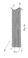
- the disclosed invention addresses the problems mentioned above by applying an encapsulation scheme as shown in Fig. 3 .
- a thin insulating film 70 is applied on top of the TF cell 20.
- another film 80 made from a metallic material is deposited to provide a permeation barrier against moisture or oxygen.
- a mechanical and electrical back protection layer 40 is applied on top the metal film for a complete encapsulation assembly.
- the first very thin insulating film closest to the TF cell 20 is an electrical insulating film 70.
- this film 70 is only a fraction of the thickness compared to typical EVA and PVB encapsulation materials 30 and therefore the moisture permeation laterally from the edge of the module to the cell can be reduced to less than 10% compared to EVA or PVD encapsulation materials 30.
- the film 70 can be spun, rolled or spray coated over the substrate 10 covered by the TF cell 20.
- a large variety of organic and inorganic materials can be used.
- resins as they are used for circuit board coating would be a very good choice since they are commercially available and show good behaviour regarding electrical insulation.
- the final thickness of the organic film depends on:
- the insulating film 70 is optimized by the following criteria:
- the film thickness is low, the diffusion cross section of the insulating film 70 to the atmosphere is low as well, reducing the air and moisture exchange nearly to zero.
- a metal film 80 is deposited on top of this insulating film 70 .
- the metal film 80 can be, e.g, Al, Cu, and is put directly onto the insulating film 70.
- the TF cell 20 is embedded in the metal layer 80 and completely protected from the environment.
- the total metal coverage can be reached by several approaches. However, since metals show a very low permeability to all TF layer-relevant gases only thin layers of metal are needed. Consequently a few (e.g. 2-3) nanometer thick up to one or two micron thick layers are applied. Our experiments have shown that a 100 nm thick aluminium film can provide sufficient sealing capabilities.
- the layer thickness of the metal film 80 strongly depends on the metal used as well as on the film quality obtained.
- the metal film 80 should be continuous and the same safety margin should be applied before defining the final film thickness.
- a method of choice for film deposition would be sputtering, which allows fast and homogeneous deposition of such thin layers at an acceptable price.
- the metal film 80 does not have to be aligned to the insulating film 70. That is, the edge of the metal film 80 needs not be flush or co-extensive with the edge of the insulating film 70. Instead, the metal film 80 is recessed from the module edge 15 of the solar collection module 100 (and also from the metal frame 90 that encases the solar collection module 100) a greater distance than the insulating film 70 located between the metal film 80 and the TF cell 20. In the illustrated embodiment, the metal film 80 is recessed a distance from the module edge 15, while the insulating film 70 extends all the way to the module edge 15.
- This arrangement allows a recess of the metal film 80 to the module edge 15 and the metal frame 90 holding the solar cell module.
- the gap between the metal frame 90 and the metal film 80 is large enough and at the same time the distance between the TF cell 20 and metal film 80 is sufficient to avoid arcing issues.
- This allows a much higher glass utilization by the energy generating TF cell area than within prior art arrangements.
- a comparison of Fig 3b with Fig. 3a will illustrate this benefit in more detail.
- a recess between the metal protection film 80 and the module edge 15 is necessary which consumes about 5-15 mm glass area measured from the module edge 15. After that distance the metal/foil arrangement starts which is necessary for the air/moisture tight sealing.
- the insulating film 70 is approaching the module edge 15 while only the metal film 80 is recessed.
- the TF cell 20 extends nearer to the module edge 15 of the glass substrate 10 (module) by about 15 mm.
- the active TF area will increase from about 1.35 m 2 to about 1.39 m 2 which is 2.6%.
- a mechanical and electrical back protection layer 40 is applied on top of one or more layers of insulating film 70 and metal film 80 .
- This mechanical back protection layer 40 protects the thin film assembly from mechanical harm like cuts during the mounting of a solar panel or mechanical weather effects. In contrast to the prior art this back protection layer 40 does not need to show any gas permeability characteristic.
- Tedlar® foils can be used in contrast to the currently used Tedlar® foils.
- the disclosed encapsulation will allow a very stable insulation of the TF cell 20 against the exposure of atmospheric gases.
- moisture sensitive TF cell materials may be used.
- One of these preferable materials would be boron-doped ZnO, which is a viable candidate TCO (transparent conductive oxide) material for cells with high efficiency.
- NIP solar cells may be possible. Insulation may be used for all cases where thin film cells must be protected against moisture or atmospheric gases.
- an encapsulation assembly for a composite solar collection module and method to produce such an encapsulation assembly are provided which pertain to the technical field initially mentioned, that overcomes the above mentioned problems.
Landscapes
- Photovoltaic Devices (AREA)
Applications Claiming Priority (2)
| Application Number | Priority Date | Filing Date | Title |
|---|---|---|---|
| US67053805P | 2005-04-11 | 2005-04-11 | |
| EP06721903A EP1869714A1 (de) | 2005-04-11 | 2006-04-10 | Solarzellenmodul und verfahren zu seiner einkapselung |
Related Parent Applications (1)
| Application Number | Title | Priority Date | Filing Date |
|---|---|---|---|
| EP06721903.0 Division | 2006-04-10 |
Publications (2)
| Publication Number | Publication Date |
|---|---|
| EP2264783A2 true EP2264783A2 (de) | 2010-12-22 |
| EP2264783A3 EP2264783A3 (de) | 2012-05-23 |
Family
ID=36602767
Family Applications (2)
| Application Number | Title | Priority Date | Filing Date |
|---|---|---|---|
| EP10010662A Ceased EP2264783A3 (de) | 2005-04-11 | 2006-04-10 | Verkapselungsanordnung für ein Sonnenkollektormodul aus Verbundwerkstoff |
| EP06721903A Ceased EP1869714A1 (de) | 2005-04-11 | 2006-04-10 | Solarzellenmodul und verfahren zu seiner einkapselung |
Family Applications After (1)
| Application Number | Title | Priority Date | Filing Date |
|---|---|---|---|
| EP06721903A Ceased EP1869714A1 (de) | 2005-04-11 | 2006-04-10 | Solarzellenmodul und verfahren zu seiner einkapselung |
Country Status (6)
| Country | Link |
|---|---|
| US (1) | US7868246B2 (de) |
| EP (2) | EP2264783A3 (de) |
| JP (1) | JP5122435B2 (de) |
| KR (1) | KR101205627B1 (de) |
| CN (1) | CN101156251B (de) |
| WO (1) | WO2006108314A1 (de) |
Cited By (4)
| Publication number | Priority date | Publication date | Assignee | Title |
|---|---|---|---|---|
| USD751498S1 (en) | 2014-10-08 | 2016-03-15 | Composite Technology Development, Inc. | Trifold solar panel |
| USD754598S1 (en) | 2014-10-08 | 2016-04-26 | Composite Technology Development, Inc. | Trifold solar panel |
| USD755118S1 (en) | 2014-10-08 | 2016-05-03 | Composite Technology Development, Inc. | Trifold solar panel |
| USD755119S1 (en) | 2014-10-08 | 2016-05-03 | Composite Technology Development, Inc. | Trifold solar panel |
Families Citing this family (31)
| Publication number | Priority date | Publication date | Assignee | Title |
|---|---|---|---|---|
| US20080302031A1 (en) * | 2007-06-05 | 2008-12-11 | Solar Roofing Systems, Inc., | Integrated solar roofing tile connection system |
| US8225496B2 (en) | 2007-08-31 | 2012-07-24 | Applied Materials, Inc. | Automated integrated solar cell production line composed of a plurality of automated modules and tools including an autoclave for curing solar devices that have been laminated |
| US20100047954A1 (en) * | 2007-08-31 | 2010-02-25 | Su Tzay-Fa Jeff | Photovoltaic production line |
| US8748727B2 (en) | 2008-01-18 | 2014-06-10 | Tenksolar, Inc. | Flat-plate photovoltaic module |
| WO2009092111A2 (en) * | 2008-01-18 | 2009-07-23 | Tenksolar, Inc. | Flat-plate photovoltaic module |
| US8933320B2 (en) | 2008-01-18 | 2015-01-13 | Tenksolar, Inc. | Redundant electrical architecture for photovoltaic modules |
| US8212139B2 (en) | 2008-01-18 | 2012-07-03 | Tenksolar, Inc. | Thin-film photovoltaic module |
| US20090188603A1 (en) * | 2008-01-25 | 2009-07-30 | Applied Materials, Inc. | Method and apparatus for controlling laminator temperature on a solar cell |
| US20090205703A1 (en) * | 2008-02-14 | 2009-08-20 | Applied Materials, Inc. | Apparatus and method of mounting and supporting a solar panel |
| DE102008013523B4 (de) * | 2008-03-07 | 2012-04-05 | Q-Cells Ag | Solarmodul mit optischer Konzentratoreinrichtung |
| DE102008013522B4 (de) * | 2008-03-07 | 2015-02-19 | Hanwha Q.CELLS GmbH | Solarmodul mit Glas-Substrat, Polymer-Versiegelungselement und im Substratrandbereich angeordneter Dichtungseinrichtung |
| US20100108140A1 (en) * | 2008-03-14 | 2010-05-06 | E. I. Du Pont De Nemours And Company | Device capable of thermally cooling while electrically insulating |
| EP2443666A4 (de) | 2009-06-15 | 2013-06-05 | Tenksolar Inc | Beleuchtungsagnostische solartafel |
| US20110017265A1 (en) * | 2009-07-23 | 2011-01-27 | Farrell James F | Photovoltaic module with conductive cooling and enhanced reflection |
| US20110017266A1 (en) * | 2009-07-24 | 2011-01-27 | Farrell James F | Thin film photovoltaic module having a lamination layer for enhanced reflection and photovoltaic output |
| US20110048495A1 (en) * | 2009-08-26 | 2011-03-03 | Satyanarayana Rao Peddada | Photovoltaic module containing a metal/polymer stack for enhanced cooling and reflection |
| KR101015824B1 (ko) * | 2009-10-27 | 2011-02-23 | 한국철강 주식회사 | 광기전력 장치 및 광기전력 장치의 제조 방법 |
| US9773933B2 (en) | 2010-02-23 | 2017-09-26 | Tenksolar, Inc. | Space and energy efficient photovoltaic array |
| US9299861B2 (en) | 2010-06-15 | 2016-03-29 | Tenksolar, Inc. | Cell-to-grid redundandt photovoltaic system |
| WO2012021650A2 (en) | 2010-08-10 | 2012-02-16 | Tenksolar, Inc. | Highly efficient solar arrays |
| JP2012080060A (ja) * | 2010-09-07 | 2012-04-19 | Mitsubishi Chemicals Corp | 有機太陽電池モジュール |
| KR101241514B1 (ko) * | 2011-10-13 | 2013-03-11 | 엘지이노텍 주식회사 | 태양광 발전장치 및 이의 제조방법 |
| KR101382739B1 (ko) * | 2012-03-06 | 2014-04-09 | 엘지이노텍 주식회사 | 태양전지 모듈 및 이의 제조 방법 |
| WO2013138008A1 (en) * | 2012-03-15 | 2013-09-19 | 3M Innovative Properties Company | Durable photovoltaic modules |
| EP2711990A1 (de) | 2012-09-21 | 2014-03-26 | Ecole Polytechnique Fédérale de Lausanne (EPFL) | Solarmodul und dessen Herstellung |
| US9728663B1 (en) | 2014-05-20 | 2017-08-08 | Solaero Technologies Corp. | Solar cell assembly and method of bonding a solar cell component to a flexible support |
| NL1041939B1 (en) * | 2016-06-21 | 2018-01-04 | Petrus Paulus Carolus Maria Stassen Ing | A solar panel and method for increasing safety and reliability of a solar panel |
| US11380813B2 (en) | 2019-02-11 | 2022-07-05 | Solaero Technologies Corp. | Metamorphic solar cells |
| US10490682B2 (en) | 2018-03-14 | 2019-11-26 | National Mechanical Group Corp. | Frame-less encapsulated photo-voltaic solar panel supporting solar cell modules encapsulated within multiple layers of optically-transparent epoxy-resin materials |
| KR102838159B1 (ko) * | 2025-03-18 | 2025-07-24 | (주)엡스코어 | 태양광모듈의 에지실링 구조 및 태양광모듈 제조방법 |
| KR102825190B1 (ko) * | 2025-03-18 | 2025-06-26 | (주)엡스코어 | 내화 및 에지실링을 구비한 G to S 구조의 프레임 일체형 태양광모듈 및 그 제조방법 |
Citations (2)
| Publication number | Priority date | Publication date | Assignee | Title |
|---|---|---|---|---|
| US6407329B1 (en) | 1999-04-07 | 2002-06-18 | Bridgestone Corporation | Backside covering member for solar battery, sealing film and solar battery |
| US20030178056A1 (en) | 2002-03-25 | 2003-09-25 | Sanyo Electric Co., Ltd. | Solar cell module |
Family Cites Families (29)
| Publication number | Priority date | Publication date | Assignee | Title |
|---|---|---|---|---|
| US4388483A (en) * | 1981-09-08 | 1983-06-14 | Monosolar, Inc. | Thin film heterojunction photovoltaic cells and methods of making the same |
| JPS61104563U (de) * | 1984-12-13 | 1986-07-03 | ||
| US4697041A (en) * | 1985-02-15 | 1987-09-29 | Teijin Limited | Integrated solar cells |
| US4726849A (en) | 1985-08-07 | 1988-02-23 | Sanyo Electric Co., Ltd | Photovoltaic device and a method of manufacturing thereof |
| JPS62232177A (ja) * | 1986-04-02 | 1987-10-12 | Mitsubishi Electric Corp | 光発電モジユ−ル |
| US4981525A (en) * | 1988-02-19 | 1991-01-01 | Sanyo Electric Co., Ltd. | Photovoltaic device |
| WO1993019491A1 (de) * | 1992-03-19 | 1993-09-30 | Siemens Solar Gmbh | Klimastabiles dünnschichtsolarmodul |
| JP3170105B2 (ja) * | 1993-07-01 | 2001-05-28 | キヤノン株式会社 | 太陽電池モジュール |
| JP2756082B2 (ja) * | 1994-04-28 | 1998-05-25 | キヤノン株式会社 | 太陽電池モジュールの製造方法 |
| EP0734075B1 (de) * | 1994-10-06 | 2009-06-17 | Kanegafuchi Kagaku Kogyo Kabushiki Kaisha | Dünnschicht-solarzelle |
| CN1169228C (zh) * | 1995-08-24 | 2004-09-29 | 佳能株式会社 | 太阳能电池组件,其制造方法以及建筑物构件 |
| US5977476A (en) * | 1996-10-16 | 1999-11-02 | United Solar Systems Corporation | High efficiency photovoltaic device |
| JPH10173210A (ja) * | 1996-12-13 | 1998-06-26 | Canon Inc | 電極、その形成方法及び該電極を有する光起電力素子 |
| JP4154004B2 (ja) * | 1997-01-06 | 2008-09-24 | キヤノン株式会社 | 太陽電池モジュールの製造方法 |
| JPH10233521A (ja) * | 1997-02-19 | 1998-09-02 | Canon Inc | 太陽電池モジュール、及びそれを用いた太陽電池一体型建材、太陽光発電装置 |
| JP2000345675A (ja) * | 1999-03-26 | 2000-12-12 | Canon Inc | 太陽電池モジュール、太陽電池付き屋根、及び太陽電池発電システム |
| JP2001044476A (ja) * | 1999-07-28 | 2001-02-16 | Canon Inc | 太陽電池モジュール |
| JP2001111076A (ja) * | 1999-10-08 | 2001-04-20 | Tdk Corp | コーティング体および太陽電池モジュール |
| JP3557148B2 (ja) * | 2000-02-21 | 2004-08-25 | 三洋電機株式会社 | 太陽電池モジュール |
| JP2002083990A (ja) * | 2000-07-06 | 2002-03-22 | Canon Inc | 光起電力素子集合体及びそれを用いた太陽電池モジュールと太陽電池モジュールの製造方法 |
| US6525264B2 (en) * | 2000-07-21 | 2003-02-25 | Sharp Kabushiki Kaisha | Thin-film solar cell module |
| JP2002134770A (ja) * | 2000-10-23 | 2002-05-10 | Toppan Printing Co Ltd | 太陽電池用裏面保護シート |
| JP4783500B2 (ja) * | 2000-12-25 | 2011-09-28 | 株式会社カネカ | 封止前準備用シートセット装置、封止前準備用出力取出し線セット装置、及び自動封止前準備装置 |
| JP2003031824A (ja) | 2001-07-13 | 2003-01-31 | Sharp Corp | 太陽電池モジュール |
| JP4061525B2 (ja) * | 2001-10-01 | 2008-03-19 | 富士電機ホールディングス株式会社 | 太陽電池モジュールの製造方法 |
| JP2004127987A (ja) * | 2002-09-30 | 2004-04-22 | Sharp Corp | 太陽電池セルおよびその製造方法 |
| JP4263009B2 (ja) * | 2003-03-27 | 2009-05-13 | 三洋電機株式会社 | 太陽電池モジュール |
| JP2005086104A (ja) * | 2003-09-10 | 2005-03-31 | Sharp Corp | 太陽電池モジュール |
| JP4681806B2 (ja) * | 2003-12-19 | 2011-05-11 | キヤノン株式会社 | 太陽電池モジュール |
-
2006
- 2006-04-10 WO PCT/CH2006/000201 patent/WO2006108314A1/en not_active Ceased
- 2006-04-10 EP EP10010662A patent/EP2264783A3/de not_active Ceased
- 2006-04-10 CN CN2006800114792A patent/CN101156251B/zh not_active Expired - Fee Related
- 2006-04-10 EP EP06721903A patent/EP1869714A1/de not_active Ceased
- 2006-04-10 KR KR1020077022953A patent/KR101205627B1/ko not_active Expired - Fee Related
- 2006-04-10 JP JP2008504602A patent/JP5122435B2/ja not_active Expired - Fee Related
- 2006-04-10 US US11/279,152 patent/US7868246B2/en not_active Expired - Fee Related
Patent Citations (2)
| Publication number | Priority date | Publication date | Assignee | Title |
|---|---|---|---|---|
| US6407329B1 (en) | 1999-04-07 | 2002-06-18 | Bridgestone Corporation | Backside covering member for solar battery, sealing film and solar battery |
| US20030178056A1 (en) | 2002-03-25 | 2003-09-25 | Sanyo Electric Co., Ltd. | Solar cell module |
Non-Patent Citations (2)
| Title |
|---|
| J. MEIER ET AL., ORLANDO SOLAR ENERGY CONFERENCE, 2005 |
| J. MUELLER, SOLAR ENERGY, vol. 77, 2004, pages 917 |
Cited By (4)
| Publication number | Priority date | Publication date | Assignee | Title |
|---|---|---|---|---|
| USD751498S1 (en) | 2014-10-08 | 2016-03-15 | Composite Technology Development, Inc. | Trifold solar panel |
| USD754598S1 (en) | 2014-10-08 | 2016-04-26 | Composite Technology Development, Inc. | Trifold solar panel |
| USD755118S1 (en) | 2014-10-08 | 2016-05-03 | Composite Technology Development, Inc. | Trifold solar panel |
| USD755119S1 (en) | 2014-10-08 | 2016-05-03 | Composite Technology Development, Inc. | Trifold solar panel |
Also Published As
| Publication number | Publication date |
|---|---|
| KR101205627B1 (ko) | 2012-11-27 |
| KR20080003801A (ko) | 2008-01-08 |
| WO2006108314A1 (en) | 2006-10-19 |
| CN101156251B (zh) | 2012-01-11 |
| EP2264783A3 (de) | 2012-05-23 |
| US7868246B2 (en) | 2011-01-11 |
| EP1869714A1 (de) | 2007-12-26 |
| US20060225777A1 (en) | 2006-10-12 |
| JP5122435B2 (ja) | 2013-01-16 |
| CN101156251A (zh) | 2008-04-02 |
| JP2008536310A (ja) | 2008-09-04 |
Similar Documents
| Publication | Publication Date | Title |
|---|---|---|
| US7868246B2 (en) | Solar cell module and method of encapsulating same | |
| US7960643B2 (en) | Isolated metallic flexible back sheet for solar module encapsulation | |
| US7829783B2 (en) | Isolated metallic flexible back sheet for solar module encapsulation | |
| KR100325955B1 (ko) | 태양전지모듈및태양전지모듈용보강부재 | |
| KR100236283B1 (ko) | 3층구조의 표면코팅재를 지닌 태양전지모듈 | |
| US6407329B1 (en) | Backside covering member for solar battery, sealing film and solar battery | |
| JP3618802B2 (ja) | 太陽電池モジュール | |
| EP1973171B1 (de) | Solarzellenmodul | |
| US20080053519A1 (en) | Laminated photovoltaic cell | |
| KR20120080589A (ko) | 유리 상의 박막 구성요소, 그의 제조 방법, 및 그의 용도 | |
| JPH10112549A (ja) | 太陽電池モジュール | |
| CN104205356A (zh) | 背接触型太阳能电池模块 | |
| US20110214716A1 (en) | Isolated metallic flexible back sheet for solar module encapsulation | |
| JP4101611B2 (ja) | 薄膜太陽電池 | |
| JPH06318728A (ja) | 太陽電池モジュール | |
| CN101989636A (zh) | 太阳能电池模块及其制造方法 | |
| JP2015195417A (ja) | 光起電モジュール製造方法およびトップシート構造製造方法 | |
| JP2012204458A (ja) | 太陽電池モジュールの製造方法 | |
| CN101958354A (zh) | 太阳能电池模块和太阳能电池模块的制造方法 | |
| JPH0945951A (ja) | 太陽電池モジュール | |
| JP2009099883A (ja) | 薄膜太陽電池モジュール | |
| JP2000307137A (ja) | 太陽電池のカバーフィルム、およびそれを用いた太陽電池モジュール | |
| JP2022087356A (ja) | 太陽電池モジュール | |
| EP4658024A1 (de) | Doppelseitiger reflektierender spaltfilm und doppelseitiges fotovoltaisches modul | |
| JP2006173298A (ja) | 太陽電池モジュール |
Legal Events
| Date | Code | Title | Description |
|---|---|---|---|
| PUAI | Public reference made under article 153(3) epc to a published international application that has entered the european phase |
Free format text: ORIGINAL CODE: 0009012 |
|
| AC | Divisional application: reference to earlier application |
Ref document number: 1869714 Country of ref document: EP Kind code of ref document: P |
|
| AK | Designated contracting states |
Kind code of ref document: A2 Designated state(s): AT BE BG CH CY CZ DE DK EE ES FI FR GB GR HU IE IS IT LI LT LU LV MC NL PL PT RO SE SI SK TR |
|
| RAP1 | Party data changed (applicant data changed or rights of an application transferred) |
Owner name: OERLIKON SOLAR AG, TRUEBBACH |
|
| PUAL | Search report despatched |
Free format text: ORIGINAL CODE: 0009013 |
|
| AK | Designated contracting states |
Kind code of ref document: A3 Designated state(s): AT BE BG CH CY CZ DE DK EE ES FI FR GB GR HU IE IS IT LI LT LU LV MC NL PL PT RO SE SI SK TR |
|
| RIC1 | Information provided on ipc code assigned before grant |
Ipc: H01L 27/142 20060101ALI20120417BHEP Ipc: H01L 31/048 20060101AFI20120417BHEP Ipc: H01L 31/0392 20060101ALI20120417BHEP |
|
| 17P | Request for examination filed |
Effective date: 20121008 |
|
| 17Q | First examination report despatched |
Effective date: 20130107 |
|
| RAP1 | Party data changed (applicant data changed or rights of an application transferred) |
Owner name: TEL SOLAR AG |
|
| STAA | Information on the status of an ep patent application or granted ep patent |
Free format text: STATUS: THE APPLICATION HAS BEEN REFUSED |
|
| 18R | Application refused |
Effective date: 20151114 |