EP2264422B1 - Prüfstandsanordnung - Google Patents
Prüfstandsanordnung Download PDFInfo
- Publication number
- EP2264422B1 EP2264422B1 EP10164599.2A EP10164599A EP2264422B1 EP 2264422 B1 EP2264422 B1 EP 2264422B1 EP 10164599 A EP10164599 A EP 10164599A EP 2264422 B1 EP2264422 B1 EP 2264422B1
- Authority
- EP
- European Patent Office
- Prior art keywords
- test
- machine
- loading
- electric machine
- test object
- Prior art date
- Legal status (The legal status is an assumption and is not a legal conclusion. Google has not performed a legal analysis and makes no representation as to the accuracy of the status listed.)
- Active
Links
Images
Classifications
-
- G—PHYSICS
- G01—MEASURING; TESTING
- G01M—TESTING STATIC OR DYNAMIC BALANCE OF MACHINES OR STRUCTURES; TESTING OF STRUCTURES OR APPARATUS, NOT OTHERWISE PROVIDED FOR
- G01M15/00—Testing of engines
- G01M15/02—Details or accessories of testing apparatus
-
- G—PHYSICS
- G01—MEASURING; TESTING
- G01M—TESTING STATIC OR DYNAMIC BALANCE OF MACHINES OR STRUCTURES; TESTING OF STRUCTURES OR APPARATUS, NOT OTHERWISE PROVIDED FOR
- G01M13/00—Testing of machine parts
- G01M13/02—Gearings; Transmission mechanisms
- G01M13/025—Test-benches with rotational drive means and loading means; Load or drive simulation
-
- G—PHYSICS
- G01—MEASURING; TESTING
- G01M—TESTING STATIC OR DYNAMIC BALANCE OF MACHINES OR STRUCTURES; TESTING OF STRUCTURES OR APPARATUS, NOT OTHERWISE PROVIDED FOR
- G01M15/00—Testing of engines
- G01M15/04—Testing internal-combustion engines
- G01M15/042—Testing internal-combustion engines by monitoring a single specific parameter not covered by groups G01M15/06 - G01M15/12
- G01M15/044—Testing internal-combustion engines by monitoring a single specific parameter not covered by groups G01M15/06 - G01M15/12 by monitoring power, e.g. by operating the engine with one of the ignitions interrupted; by using acceleration tests
Definitions
- the invention relates to a test rig with a test specimen, which is connected by a connecting shaft with adapter flange and Drehmomentmessflansch with an electric machine for driving and / or loading of the test specimen, as well as with a control arrangement for the electric machine for driving and / or loading of the test specimen, the arrangement from connecting shaft and drive and loading machine has a constant, predetermined moment of inertia.
- a conventional engine test stand for an internal combustion engine which is connected via a connecting shaft with a drive and loading machine is, for example, from AT 9 782 U2 known.
- Current test bed systems can only simulate such powertrain simulations up to approx. 8-10 Hz, which has proved to be insufficient.
- the US 2002/0091471 A1 shows an engine test bench with internal combustion engine, connecting shaft and a drive and loading machine whose natural frequency is set above 100Hz. To perform tests with this test rig arrangement To be able to control a resonance control unit is provided, which suppresses resonance during the test.
- test rig in particular an engine test stand
- cyclical nonuniformity of the internal combustion engine should be reproducible in detail and excited frequencies from the powertrain simulation, up to 40Hz, can be transferred to the engine.
- the invention provides that the mass and the moment of inertia of the adapter flange is chosen such that the natural frequency of the system of DUT, adapter flange, connecting shaft and Eektromaschine for driving and / or load of the DUT is between the idling frequency and a partial load frequency of the DUT ,
- the realistic representation of "real" combustion surges with dropouts or hybrid-relevant start / stop operation in combination with sophisticated vehicle simulation can now also be implemented on the test bench.
- this test rig configuration is ideally suited for work in the engine and drivetrain sector, which must have a high correlation to the real transient vehicle behavior.
- a particularly important topic is the representation of powertrain vibrations up to 40Hz with the possibility of safe and accurate control of the mechanical vibration system engine - shaft - load unit in this frequency range, i. at a lying in the engine operating range mechanical natural frequency of the test rig.
- the moment of inertia of the adapter flange is chosen such that the natural frequency of the system is between 10 Hz and 100 Hz, preferably between 20 Hz and 60 Hz.
- the connecting shaft is designed as a Geichlaufgeschwelle.
- the electric machine for driving and / or loading of the test specimen has the largest possible ratio of torque to moment of inertia.
- the two features mentioned are responsible for that the electric machine for drive and / or load of the specimen has high acceleration capability (deceleration).
- the electric machine for driving and / or loading of the test specimen, in particular its rotor, prepared for angle synchronous, jerky, high torque loads is provided.
- the above requirements can be implemented if the drive and loading machine as a three-phase-powered three-phase machine, preferably As an asynchronous machine, foreign-excited or permanent magnet-excited synchronous machine is executed.
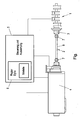
- the drawing figure shows a schematic representation of a test stand arrangement, for example an engine test stand, with an internal combustion engine as the test object 1, which is symbolized by its crankshaft.
- This test piece 1 is connected via a shaft 2 and an adapter flange 3 with an electric machine 4 for driving and / or loading of the test piece 1.
- the control and evaluation unit 5, which may also be parts of a still higher-level test stand automation system, also comprises a control arrangement 6 for the electric machine 4. While the test object 1 is constructed in real terms, components which can be connected thereto can be replaced by simulation, for which purpose at least one model is implemented for such connectable to the device under test components 1 in the control arrangement 6, from which model then the control request to the electric machine 4 is determined.
- the arrangement of connecting shaft 2 and electric machine 4 has a constant, predetermined moment of inertia.
- the mass and moment of inertia of the adapter flange 3 are selected so that the natural frequency of the system under test 1, adapter flange 3, connecting shaft 2 and electric machine 4 between the idling frequency and a partial load frequency of the specimen 1, i. preferably between about 20 and 60Hz.
- a realistic representation of the cyclical nonuniformity of the internal combustion engine as the test object 1 is possible since excited frequencies from the powertrain simulation or other models can be transmitted to the internal combustion engine.
- the wave 2 acts as a low-pass filter with respect to previous constructions upwardly shifted low-pass frequency.
- the safe and accurate compensation of the mechanical vibration system DUT 1, adapter flange 3, connecting shaft 2 and electric machine 4 in this frequency range, ie at a lying in the engine operating range mechanical natural frequency of the test bed, be supported by a suitable control strategy.
- the control arrangement 6 comprises, for example, a controller and an actual value calculation unit, which is arranged in a feedback branch.
- the actual value calculation unit a current actual value of the control and a prediction of an imminent, system delay-free actual value can be processed on the basis of the actual value of a previous work cycle to form a modified actual value which is fed back to the control.
- the connecting shaft 2 is designed as a constant velocity universal joint shaft. It has two constant velocity joints 7 at the ends of a steel tube 8 with adapted rigidity and torque transmission capability. Due to the constant velocity joints 7, the geometric alignment of the test piece 1 and the electric machine 4 is not so critical and can be performed very easily in comparison with conventionally used torsion bars. Also, one and the same shaft 2 can be used for many different test specimens 1, whereas so far for each specimen 1, the design of the shaft 2 recalculated and a specially tuned shaft 2 had to be installed.
- the drive and / or load unit 4 has the lowest possible moment of inertia for the good simulatory simulation of the repercussions of the components connected to the device under test 1, as well as preferably the largest possible ratio of torque to moment of inertia.
- the two features mentioned ensure the necessary high acceleration capability (deceleration), which is expressed by the value "revolutions per unit time" (rpm / sec), which is advantageously not less than 30,000 rpm / sec and from the nominal torque, the possible overload and the inertia mass of the machine is calculated.
- the electric machine 4 in particular its rotor, prepared for angle-synchronous, jerky, high torque loads. Measures for avoiding eddy currents and thus excessive heat development also contribute, in particular in the area of de (r) mounting rings of the electric machine 4.
- the electric machine 4 is designed as a three-phase three-phase machine, preferably as an asynchronous machine, a separately excited or permanently magnet-excited synchronous machine.
- the realistic imaging of the rotational irregularity in the entire speed band of an internal combustion engine as the test object 1 is possible.
- This is the basis for the transfer of SOP-oriented development and calibration tasks from the vehicle to the engine test bench (eg drivability, OBD, start / stop, ancillary engine development, structure-borne noise analyzes etc).
- SOP-oriented development and calibration tasks from the vehicle to the engine test bench (eg drivability, OBD, start / stop, ancillary engine development, structure-borne noise analyzes etc).
- OBD relevant rotational nonuniformity signal can be obtained as in the vehicle by the inventive test rig, which was previously not feasible on any engine test, as conventional test stand systems, in combination with conventional control, smooth this behavior.
- Driveability is the subjective feeling of a driver interacting with a vehicle.
- driving performance and consumption for example on the powertrain test bench, and of consumption and emissions on the chassis dynamometer.
- the tuning of driveability is performed almost exclusively in the vehicle based on subjective evaluations by test drivers. However, if satisfactory drivability tuning is not achieved in the vehicle, it will not be possible to prevent repetitive loops in the development process. A global, common optimum can only be found to be difficult due to the separate coordination of the development goals.
- the above problems can be circumvented. Thanks to the integration on the engine test bench, numerous coordination tasks can now be carried out earlier in the development process.
- the tuning of the test rig arrangement according to the invention to a natural frequency of the system between 10 Hz and 100 Hz, preferably between 20 Hz and 60 Hz, is advantageous since many drivability maneuvers cause vibrations in this range. For example, vibrations of the drivability maneuver "tip-in" (positive load stroke by the accelerator pedal) reach up to 40 Hz.
- the test rig arrangement according to the invention also allows the time-saving and material-saving investigation of questions on the effects of various connected components by the simulation of their reaction in said frequency range, such as starting and stopping, without having to perform experiments with a variety of real components.
- no expensive test vehicles or component prototypes are necessary, the representation of hardware changes or variants in a very short time is possible, other components can be replaced faster than in real vehicles, the tests are very well compared with each other, since development environment always remains constant, and If required, comprehensive measuring equipment can be used.
Landscapes
- Physics & Mathematics (AREA)
- General Physics & Mathematics (AREA)
- Chemical & Material Sciences (AREA)
- Engineering & Computer Science (AREA)
- Combustion & Propulsion (AREA)
- Testing Of Engines (AREA)
- Testing Of Devices, Machine Parts, Or Other Structures Thereof (AREA)
Priority Applications (1)
| Application Number | Priority Date | Filing Date | Title |
|---|---|---|---|
| PL10164599T PL2264422T3 (pl) | 2009-06-16 | 2010-06-01 | Układ stanowiska badawczego |
Applications Claiming Priority (1)
| Application Number | Priority Date | Filing Date | Title |
|---|---|---|---|
| AT0036909U AT10812U3 (de) | 2009-06-16 | 2009-06-16 | Prüfstandsanordnung |
Publications (3)
| Publication Number | Publication Date |
|---|---|
| EP2264422A2 EP2264422A2 (de) | 2010-12-22 |
| EP2264422A3 EP2264422A3 (de) | 2014-07-02 |
| EP2264422B1 true EP2264422B1 (de) | 2015-09-09 |
Family
ID=40935217
Family Applications (1)
| Application Number | Title | Priority Date | Filing Date |
|---|---|---|---|
| EP10164599.2A Active EP2264422B1 (de) | 2009-06-16 | 2010-06-01 | Prüfstandsanordnung |
Country Status (7)
| Country | Link |
|---|---|
| US (1) | US8418542B2 (zh) |
| EP (1) | EP2264422B1 (zh) |
| JP (1) | JP5150680B2 (zh) |
| CN (1) | CN101957262B (zh) |
| AT (1) | AT10812U3 (zh) |
| HU (1) | HUE028256T2 (zh) |
| PL (1) | PL2264422T3 (zh) |
Families Citing this family (17)
| Publication number | Priority date | Publication date | Assignee | Title |
|---|---|---|---|---|
| US8590369B2 (en) * | 2010-12-23 | 2013-11-26 | Horiba Instruments, Inc. | Vehicle drivetrain test stand and method of controlling same |
| AT510378B1 (de) * | 2011-12-15 | 2012-09-15 | Avl List Gmbh | Verfahren und prüfstand zum testen eines startermotors |
| AT512186B1 (de) * | 2012-04-18 | 2013-06-15 | Avl List Gmbh | Motorenprüfstand |
| DE102014226515B4 (de) * | 2014-12-19 | 2020-02-13 | Zf Friedrichshafen Ag | Getriebeprüfstand |
| CN104656556B (zh) * | 2015-01-23 | 2017-10-13 | 清能德创电气技术(北京)有限公司 | 一种基于参考模型自适应的惯量比调节方法 |
| KR101660406B1 (ko) * | 2015-07-13 | 2016-09-30 | 재단법인경북테크노파크 | 모터의 nvh 성능시험장치 |
| CN105258949A (zh) * | 2015-10-03 | 2016-01-20 | 李志勇 | 一种发动机安装支架及其工艺方法 |
| KR101962849B1 (ko) * | 2015-11-10 | 2019-03-27 | 이래에이엠에스 주식회사 | 차량용 드라이브 샤프트의 다목적 시험장치 |
| AT519261B1 (de) * | 2016-12-05 | 2018-05-15 | Avl List Gmbh | Verfahren und Prüfstand zum Durchführen eines Prüflaufs mit einem Antriebsstrang |
| KR101919549B1 (ko) * | 2016-12-05 | 2018-11-16 | 코리아테스팅 주식회사 | 제어 안정성 및 신뢰성이 향상된 하이브리드 서보 액추에이터 |
| KR101921302B1 (ko) * | 2016-12-05 | 2018-11-22 | 코리아테스팅 주식회사 | 기계적인 트리거 기능을 이용한 응답성능 개선 하이브리드 서보 액추에이터 |
| CN106706327A (zh) * | 2017-01-19 | 2017-05-24 | 浙江大学 | 一种发动机燃烧过程实验研究装置 |
| AT520185B1 (de) * | 2017-12-04 | 2019-02-15 | Avl List Gmbh | Prüfstand und Verfahren zur Durchführung eines Prüfversuchs |
| CN108087155B (zh) * | 2017-12-19 | 2024-02-09 | 西安航天动力研究所 | 一种大流量液体输送系统频率特性试验系统的试验方法 |
| AT522555B1 (de) * | 2019-05-14 | 2020-12-15 | Tectos Gmbh | Verfahren zur echtzeit-analyse innermotorischer prozesse |
| AT522354B1 (de) * | 2019-08-12 | 2020-10-15 | Avl List Gmbh | Verfahren zum Betreiben eines Prüfstands |
| US11790126B2 (en) | 2019-12-19 | 2023-10-17 | Caterpillar Inc. | Method and system for internal combustion engine simulation |
Family Cites Families (31)
| Publication number | Priority date | Publication date | Assignee | Title |
|---|---|---|---|---|
| DE660989C (de) * | 1934-04-17 | 1938-06-08 | Versuchsanstalt Fuer Luftfahrt | Motorenpruefstand mit einem federnd gegen das Fundament abgestuetzten Motortraeger |
| AT263089B (de) * | 1965-11-23 | 1968-07-10 | Telefunken Patent | Schaltungsanordnung mit Kapazitätsdioden |
| US4382388A (en) * | 1979-10-31 | 1983-05-10 | Kabushiki Kaisha Ono Sokki | Dynamometer road simulating method and system |
| US4466294A (en) * | 1981-12-31 | 1984-08-21 | Edi | Transient driving cycle simulator test system |
| US4899595A (en) * | 1989-02-17 | 1990-02-13 | Warsaw Arthur J | Modular dynamometer with extended testing range |
| US5452605A (en) * | 1991-02-08 | 1995-09-26 | Clayton Industries | Dynamometer for simulating the inertial and road load forces encountered by motor vehicles |
| JPH0523094U (ja) * | 1991-09-11 | 1993-03-26 | 株式会社明電舎 | 自動車用エンジンのテストスタンド |
| US5375460A (en) * | 1993-04-09 | 1994-12-27 | Clayton Industries | Method and apparatus for testing motor vehicles under simulated road conditions |
| US5445013A (en) * | 1993-08-30 | 1995-08-29 | Clayton Industries | Dynamometer for simulating the inertial and road load forces encountered by motor vehicles and method |
| US5465612A (en) * | 1994-06-16 | 1995-11-14 | Clayton Industries | Method and apparatus for testing motor vehicles under simulated road conditions |
| EP0704689B1 (de) * | 1994-09-30 | 2003-04-16 | AVL List GmbH | Verfahren zur Trägheitsmomentbestimmung |
| JPH09178616A (ja) * | 1995-12-25 | 1997-07-11 | Meidensha Corp | 車両用試験装置 |
| JP3424458B2 (ja) * | 1996-09-27 | 2003-07-07 | トヨタ自動車株式会社 | 車両運転性評価装置 |
| JP3405924B2 (ja) | 1998-07-21 | 2003-05-12 | トヨタ自動車株式会社 | 負荷伝達装置 |
| JP3405925B2 (ja) * | 1998-07-22 | 2003-05-12 | トヨタ自動車株式会社 | エンジンの試験装置 |
| JP4020513B2 (ja) * | 1998-09-30 | 2007-12-12 | トヨタ自動車株式会社 | 原動機の試験装置 |
| US6360591B1 (en) * | 2000-03-02 | 2002-03-26 | Burke E. Porter Machinery Company | Method of controlling a chassis dynamometer |
| US6651493B2 (en) * | 2000-05-04 | 2003-11-25 | Hicklin Engineering, L.C. | Torque converter dynamometer and method of using same |
| JP3918435B2 (ja) * | 2001-01-11 | 2007-05-23 | 株式会社明電舎 | 自動車部品の試験装置 |
| JP2003207424A (ja) * | 2002-01-09 | 2003-07-25 | Meidensha Corp | エンジンベンチシステム |
| US6860145B2 (en) * | 2003-04-14 | 2005-03-01 | Power Test, Inc. | Chassis dynamometer |
| JP2007522452A (ja) * | 2004-02-03 | 2007-08-09 | ドラッグ タグ ピーティーワイ リミテッド | ダイナモメータ用車両固定機構 |
| JP4207810B2 (ja) * | 2004-03-11 | 2009-01-14 | 神鋼電機株式会社 | Pmモータの評価試験装置 |
| AT7073U3 (de) * | 2004-05-24 | 2005-05-25 | Avl List Gmbh | Prüfstand für brennkraftmaschinen |
| JP2006271057A (ja) | 2005-03-23 | 2006-10-05 | Toshiba Mitsubishi-Electric Industrial System Corp | 永久磁石同期電動機の回転子 |
| JP4837940B2 (ja) * | 2005-05-18 | 2011-12-14 | 株式会社エー・アンド・デイ | 回転型分力計測装置 |
| JP4788543B2 (ja) * | 2006-09-19 | 2011-10-05 | 株式会社明電舎 | エンジンベンチシステムのパラメータ推定装置 |
| JP4788627B2 (ja) * | 2007-02-20 | 2011-10-05 | 株式会社明電舎 | エンジンベンチシステムのパラメータ推定装置 |
| JP4333767B2 (ja) * | 2007-04-03 | 2009-09-16 | 株式会社デンソー | 車両制御装置 |
| AT9782U3 (de) * | 2007-10-11 | 2008-10-15 | Avl List Gmbh | Drehmoment-messflansch |
| US7926336B2 (en) * | 2008-09-04 | 2011-04-19 | Vickio Jr Louis P | Dynamometer |
-
2009
- 2009-06-16 AT AT0036909U patent/AT10812U3/de not_active IP Right Cessation
-
2010
- 2010-06-01 PL PL10164599T patent/PL2264422T3/pl unknown
- 2010-06-01 EP EP10164599.2A patent/EP2264422B1/de active Active
- 2010-06-01 HU HUE10164599A patent/HUE028256T2/en unknown
- 2010-06-12 CN CN2010102130675A patent/CN101957262B/zh active Active
- 2010-06-15 US US12/801,581 patent/US8418542B2/en active Active
- 2010-06-15 JP JP2010136141A patent/JP5150680B2/ja active Active
Also Published As
| Publication number | Publication date |
|---|---|
| AT10812U3 (de) | 2010-03-15 |
| JP5150680B2 (ja) | 2013-02-20 |
| HUE028256T2 (en) | 2016-12-28 |
| PL2264422T3 (pl) | 2016-04-29 |
| US20110000291A1 (en) | 2011-01-06 |
| US8418542B2 (en) | 2013-04-16 |
| EP2264422A2 (de) | 2010-12-22 |
| AT10812U2 (de) | 2009-10-15 |
| CN101957262B (zh) | 2012-07-04 |
| JP2011002455A (ja) | 2011-01-06 |
| CN101957262A (zh) | 2011-01-26 |
| EP2264422A3 (de) | 2014-07-02 |
Similar Documents
| Publication | Publication Date | Title |
|---|---|---|
| EP2264422B1 (de) | Prüfstandsanordnung | |
| EP2264421B1 (de) | Prüfstandsanordnung | |
| DE10162786B4 (de) | Verfahren zur Leistungsermittlung, Messvorrichtung und Leistungsprüfstand für einen Prüfling | |
| AT517689B1 (de) | Verfahren zum Erstellen eines Prüfversuchs | |
| EP2321708B1 (de) | Verfahren und regelanordnung zur regelung einer regelstrecke mit sich wiederholendem arbeitszyklus | |
| AT508909B1 (de) | Verfahren und einrichtung zur regelung einer prüfstandsanordnung | |
| AT514725B1 (de) | Verfahren und eine Vorrichtung zur Ermittlung des Vortriebsmoments | |
| WO2013053461A1 (de) | Verfahren und vorrichtung zum erkennen von drehzahl-/drehmomentschwankungen in einer antriebsvorrichtung | |
| DE102007016420A1 (de) | Prüfstand und Verfahren zum Überprüfen eines Antriebsstrangs | |
| EP3729041B1 (de) | Verfahren zum betreiben eines prüfstands | |
| EP3059569A2 (de) | Verfahren zur teilphysikalischen echtzeitsimulation | |
| EP2019303A1 (de) | Verfahren zum Auswuchten eines Fahrzeugrades | |
| DE102018218622A1 (de) | Verfahren zum Re-Integrieren eines Verbrennungsmotors in einen Antriebsstrang eines Fahrzeuges | |
| EP1574835B1 (de) | Verfahren und Steuergerät zum Bereinigen eines Drehzahlsignals | |
| DE102010007735A1 (de) | Verfahren zum Ermitteln und/oder Überwachen des Zustandes von technischen Komponenten und/oder Regelsystemen eines Kraftfahrzeuges | |
| DE102013202706A1 (de) | Anordnung für einen Getriebelastprüfstand | |
| EP1382956A2 (de) | Verfahren zur Simulation des Fahrverhaltens von Fahrzeugen | |
| EP1333268A2 (de) | Verfahren und Vorrichtung zum Prüfen eines Fahrzeug-Antriebsstranges | |
| EP1459043B1 (de) | Verfahren zur leistungsermittlung und leistungsprüfstand für einen verbrennungsmotor | |
| EP3279633B1 (de) | Prüfvorrichtung zur prüfung oder erprobung eines prüfgegenstands | |
| DE102018102202A1 (de) | Vorrichtung und Verfahren zur Zustandsüberwachung einer Elastomerkupplung oder eines Zweimassenschwungrades oder eines Torsionsdämpfers | |
| DE102012000836A1 (de) | Getriebeprüfstandeinrichtung für Getriebe, insbesondere für Windkraftanlagen, mit einem im Antriebsstrang integrierten Generator | |
| DE102015120263B4 (de) | Verfahren zur Verschleißbestimmung, Messgerät, Steuervorrichtung dazu sowie Antriebsvorrichtung umfassend die Steuervorrichtung | |
| AT523048B1 (de) | Vorrichtung, Referenzfahrzeug mit einer Vorrichtung und Verfahren zur Bewertung und/oder Kalibrierung eines Prüfstands | |
| DE10038281A1 (de) | Verfahren und Vorrichtung zur Reduktion von Schwingungen in einem Antriebssystem, sowie Steuereinrichtung für ein Antriebssystem |
Legal Events
| Date | Code | Title | Description |
|---|---|---|---|
| PUAI | Public reference made under article 153(3) epc to a published international application that has entered the european phase |
Free format text: ORIGINAL CODE: 0009012 |
|
| AK | Designated contracting states |
Kind code of ref document: A2 Designated state(s): AL AT BE BG CH CY CZ DE DK EE ES FI FR GB GR HR HU IE IS IT LI LT LU LV MC MK MT NL NO PL PT RO SE SI SK SM TR |
|
| AX | Request for extension of the european patent |
Extension state: BA ME RS |
|
| PUAL | Search report despatched |
Free format text: ORIGINAL CODE: 0009013 |
|
| AK | Designated contracting states |
Kind code of ref document: A3 Designated state(s): AL AT BE BG CH CY CZ DE DK EE ES FI FR GB GR HR HU IE IS IT LI LT LU LV MC MK MT NL NO PL PT RO SE SI SK SM TR |
|
| AX | Request for extension of the european patent |
Extension state: BA ME RS |
|
| RIC1 | Information provided on ipc code assigned before grant |
Ipc: G01M 15/04 20060101ALI20140527BHEP Ipc: G01M 15/02 20060101AFI20140527BHEP |
|
| 17P | Request for examination filed |
Effective date: 20140829 |
|
| RBV | Designated contracting states (corrected) |
Designated state(s): AL AT BE BG CH CY CZ DE DK EE ES FI FR GB GR HR HU IE IS IT LI LT LU LV MC MK MT NL NO PL PT RO SE SI SK SM TR |
|
| REG | Reference to a national code |
Ref country code: DE Ref legal event code: R079 Ref document number: 502010010233 Country of ref document: DE Free format text: PREVIOUS MAIN CLASS: G01M0015020000 Ipc: G01M0013020000 |
|
| RIC1 | Information provided on ipc code assigned before grant |
Ipc: G01M 15/02 20060101ALI20150122BHEP Ipc: G01M 13/02 20060101AFI20150122BHEP Ipc: G01M 15/04 20060101ALI20150122BHEP |
|
| GRAP | Despatch of communication of intention to grant a patent |
Free format text: ORIGINAL CODE: EPIDOSNIGR1 |
|
| INTG | Intention to grant announced |
Effective date: 20150410 |
|
| GRAS | Grant fee paid |
Free format text: ORIGINAL CODE: EPIDOSNIGR3 |
|
| GRAA | (expected) grant |
Free format text: ORIGINAL CODE: 0009210 |
|
| AK | Designated contracting states |
Kind code of ref document: B1 Designated state(s): AL AT BE BG CH CY CZ DE DK EE ES FI FR GB GR HR HU IE IS IT LI LT LU LV MC MK MT NL NO PL PT RO SE SI SK SM TR |
|
| REG | Reference to a national code |
Ref country code: GB Ref legal event code: FG4D Free format text: NOT ENGLISH |
|
| REG | Reference to a national code |
Ref country code: AT Ref legal event code: REF Ref document number: 748514 Country of ref document: AT Kind code of ref document: T Effective date: 20150915 Ref country code: CH Ref legal event code: EP |
|
| REG | Reference to a national code |
Ref country code: IE Ref legal event code: FG4D Free format text: LANGUAGE OF EP DOCUMENT: GERMAN |
|
| REG | Reference to a national code |
Ref country code: DE Ref legal event code: R096 Ref document number: 502010010233 Country of ref document: DE |
|
| REG | Reference to a national code |
Ref country code: SE Ref legal event code: TRGR |
|
| REG | Reference to a national code |
Ref country code: NL Ref legal event code: MP Effective date: 20150909 |
|
| PG25 | Lapsed in a contracting state [announced via postgrant information from national office to epo] |
Ref country code: GR Free format text: LAPSE BECAUSE OF FAILURE TO SUBMIT A TRANSLATION OF THE DESCRIPTION OR TO PAY THE FEE WITHIN THE PRESCRIBED TIME-LIMIT Effective date: 20151210 Ref country code: LT Free format text: LAPSE BECAUSE OF FAILURE TO SUBMIT A TRANSLATION OF THE DESCRIPTION OR TO PAY THE FEE WITHIN THE PRESCRIBED TIME-LIMIT Effective date: 20150909 Ref country code: FI Free format text: LAPSE BECAUSE OF FAILURE TO SUBMIT A TRANSLATION OF THE DESCRIPTION OR TO PAY THE FEE WITHIN THE PRESCRIBED TIME-LIMIT Effective date: 20150909 Ref country code: LV Free format text: LAPSE BECAUSE OF FAILURE TO SUBMIT A TRANSLATION OF THE DESCRIPTION OR TO PAY THE FEE WITHIN THE PRESCRIBED TIME-LIMIT Effective date: 20150909 Ref country code: NO Free format text: LAPSE BECAUSE OF FAILURE TO SUBMIT A TRANSLATION OF THE DESCRIPTION OR TO PAY THE FEE WITHIN THE PRESCRIBED TIME-LIMIT Effective date: 20151209 |
|
| REG | Reference to a national code |
Ref country code: LT Ref legal event code: MG4D |
|
| PG25 | Lapsed in a contracting state [announced via postgrant information from national office to epo] |
Ref country code: ES Free format text: LAPSE BECAUSE OF FAILURE TO SUBMIT A TRANSLATION OF THE DESCRIPTION OR TO PAY THE FEE WITHIN THE PRESCRIBED TIME-LIMIT Effective date: 20150909 Ref country code: HR Free format text: LAPSE BECAUSE OF FAILURE TO SUBMIT A TRANSLATION OF THE DESCRIPTION OR TO PAY THE FEE WITHIN THE PRESCRIBED TIME-LIMIT Effective date: 20150909 |
|
| PG25 | Lapsed in a contracting state [announced via postgrant information from national office to epo] |
Ref country code: NL Free format text: LAPSE BECAUSE OF FAILURE TO SUBMIT A TRANSLATION OF THE DESCRIPTION OR TO PAY THE FEE WITHIN THE PRESCRIBED TIME-LIMIT Effective date: 20150909 |
|
| PG25 | Lapsed in a contracting state [announced via postgrant information from national office to epo] |
Ref country code: CZ Free format text: LAPSE BECAUSE OF FAILURE TO SUBMIT A TRANSLATION OF THE DESCRIPTION OR TO PAY THE FEE WITHIN THE PRESCRIBED TIME-LIMIT Effective date: 20150909 Ref country code: SK Free format text: LAPSE BECAUSE OF FAILURE TO SUBMIT A TRANSLATION OF THE DESCRIPTION OR TO PAY THE FEE WITHIN THE PRESCRIBED TIME-LIMIT Effective date: 20150909 Ref country code: IS Free format text: LAPSE BECAUSE OF FAILURE TO SUBMIT A TRANSLATION OF THE DESCRIPTION OR TO PAY THE FEE WITHIN THE PRESCRIBED TIME-LIMIT Effective date: 20160109 Ref country code: EE Free format text: LAPSE BECAUSE OF FAILURE TO SUBMIT A TRANSLATION OF THE DESCRIPTION OR TO PAY THE FEE WITHIN THE PRESCRIBED TIME-LIMIT Effective date: 20150909 |
|
| PG25 | Lapsed in a contracting state [announced via postgrant information from national office to epo] |
Ref country code: RO Free format text: LAPSE BECAUSE OF FAILURE TO SUBMIT A TRANSLATION OF THE DESCRIPTION OR TO PAY THE FEE WITHIN THE PRESCRIBED TIME-LIMIT Effective date: 20150909 Ref country code: PT Free format text: LAPSE BECAUSE OF FAILURE TO SUBMIT A TRANSLATION OF THE DESCRIPTION OR TO PAY THE FEE WITHIN THE PRESCRIBED TIME-LIMIT Effective date: 20160111 |
|
| REG | Reference to a national code |
Ref country code: DE Ref legal event code: R097 Ref document number: 502010010233 Country of ref document: DE |
|
| REG | Reference to a national code |
Ref country code: FR Ref legal event code: PLFP Year of fee payment: 7 |
|
| PLBE | No opposition filed within time limit |
Free format text: ORIGINAL CODE: 0009261 |
|
| STAA | Information on the status of an ep patent application or granted ep patent |
Free format text: STATUS: NO OPPOSITION FILED WITHIN TIME LIMIT |
|
| 26N | No opposition filed |
Effective date: 20160610 |
|
| PG25 | Lapsed in a contracting state [announced via postgrant information from national office to epo] |
Ref country code: DK Free format text: LAPSE BECAUSE OF FAILURE TO SUBMIT A TRANSLATION OF THE DESCRIPTION OR TO PAY THE FEE WITHIN THE PRESCRIBED TIME-LIMIT Effective date: 20150909 Ref country code: SI Free format text: LAPSE BECAUSE OF FAILURE TO SUBMIT A TRANSLATION OF THE DESCRIPTION OR TO PAY THE FEE WITHIN THE PRESCRIBED TIME-LIMIT Effective date: 20150909 |
|
| REG | Reference to a national code |
Ref country code: HU Ref legal event code: AG4A Ref document number: E028256 Country of ref document: HU |
|
| PG25 | Lapsed in a contracting state [announced via postgrant information from national office to epo] |
Ref country code: BE Free format text: LAPSE BECAUSE OF NON-PAYMENT OF DUE FEES Effective date: 20160630 |
|
| PG25 | Lapsed in a contracting state [announced via postgrant information from national office to epo] |
Ref country code: MC Free format text: LAPSE BECAUSE OF FAILURE TO SUBMIT A TRANSLATION OF THE DESCRIPTION OR TO PAY THE FEE WITHIN THE PRESCRIBED TIME-LIMIT Effective date: 20150909 |
|
| REG | Reference to a national code |
Ref country code: CH Ref legal event code: PL |
|
| REG | Reference to a national code |
Ref country code: IE Ref legal event code: MM4A |
|
| PG25 | Lapsed in a contracting state [announced via postgrant information from national office to epo] |
Ref country code: CH Free format text: LAPSE BECAUSE OF NON-PAYMENT OF DUE FEES Effective date: 20160630 Ref country code: LI Free format text: LAPSE BECAUSE OF NON-PAYMENT OF DUE FEES Effective date: 20160630 |
|
| PG25 | Lapsed in a contracting state [announced via postgrant information from national office to epo] |
Ref country code: IE Free format text: LAPSE BECAUSE OF NON-PAYMENT OF DUE FEES Effective date: 20160601 |
|
| REG | Reference to a national code |
Ref country code: FR Ref legal event code: PLFP Year of fee payment: 8 |
|
| PG25 | Lapsed in a contracting state [announced via postgrant information from national office to epo] |
Ref country code: SM Free format text: LAPSE BECAUSE OF FAILURE TO SUBMIT A TRANSLATION OF THE DESCRIPTION OR TO PAY THE FEE WITHIN THE PRESCRIBED TIME-LIMIT Effective date: 20150909 Ref country code: CY Free format text: LAPSE BECAUSE OF FAILURE TO SUBMIT A TRANSLATION OF THE DESCRIPTION OR TO PAY THE FEE WITHIN THE PRESCRIBED TIME-LIMIT Effective date: 20150909 |
|
| REG | Reference to a national code |
Ref country code: FR Ref legal event code: PLFP Year of fee payment: 9 |
|
| PG25 | Lapsed in a contracting state [announced via postgrant information from national office to epo] |
Ref country code: MK Free format text: LAPSE BECAUSE OF FAILURE TO SUBMIT A TRANSLATION OF THE DESCRIPTION OR TO PAY THE FEE WITHIN THE PRESCRIBED TIME-LIMIT Effective date: 20150909 Ref country code: LU Free format text: LAPSE BECAUSE OF NON-PAYMENT OF DUE FEES Effective date: 20160601 Ref country code: TR Free format text: LAPSE BECAUSE OF FAILURE TO SUBMIT A TRANSLATION OF THE DESCRIPTION OR TO PAY THE FEE WITHIN THE PRESCRIBED TIME-LIMIT Effective date: 20150909 Ref country code: MT Free format text: LAPSE BECAUSE OF FAILURE TO SUBMIT A TRANSLATION OF THE DESCRIPTION OR TO PAY THE FEE WITHIN THE PRESCRIBED TIME-LIMIT Effective date: 20150909 |
|
| PG25 | Lapsed in a contracting state [announced via postgrant information from national office to epo] |
Ref country code: BG Free format text: LAPSE BECAUSE OF FAILURE TO SUBMIT A TRANSLATION OF THE DESCRIPTION OR TO PAY THE FEE WITHIN THE PRESCRIBED TIME-LIMIT Effective date: 20150909 |
|
| PG25 | Lapsed in a contracting state [announced via postgrant information from national office to epo] |
Ref country code: AL Free format text: LAPSE BECAUSE OF FAILURE TO SUBMIT A TRANSLATION OF THE DESCRIPTION OR TO PAY THE FEE WITHIN THE PRESCRIBED TIME-LIMIT Effective date: 20150909 |
|
| PGFP | Annual fee paid to national office [announced via postgrant information from national office to epo] |
Ref country code: PL Payment date: 20200529 Year of fee payment: 11 Ref country code: HU Payment date: 20200603 Year of fee payment: 11 Ref country code: SE Payment date: 20200623 Year of fee payment: 11 |
|
| REG | Reference to a national code |
Ref country code: SE Ref legal event code: EUG |
|
| PG25 | Lapsed in a contracting state [announced via postgrant information from national office to epo] |
Ref country code: HU Free format text: LAPSE BECAUSE OF NON-PAYMENT OF DUE FEES Effective date: 20210602 |
|
| PG25 | Lapsed in a contracting state [announced via postgrant information from national office to epo] |
Ref country code: SE Free format text: LAPSE BECAUSE OF NON-PAYMENT OF DUE FEES Effective date: 20210602 |
|
| PG25 | Lapsed in a contracting state [announced via postgrant information from national office to epo] |
Ref country code: PL Free format text: LAPSE BECAUSE OF NON-PAYMENT OF DUE FEES Effective date: 20210601 |
|
| P01 | Opt-out of the competence of the unified patent court (upc) registered |
Effective date: 20230502 |
|
| PGFP | Annual fee paid to national office [announced via postgrant information from national office to epo] |
Ref country code: FR Payment date: 20230628 Year of fee payment: 14 Ref country code: DE Payment date: 20230629 Year of fee payment: 14 |
|
| PGFP | Annual fee paid to national office [announced via postgrant information from national office to epo] |
Ref country code: AT Payment date: 20230629 Year of fee payment: 14 |
|
| PGFP | Annual fee paid to national office [announced via postgrant information from national office to epo] |
Ref country code: IT Payment date: 20230629 Year of fee payment: 14 Ref country code: GB Payment date: 20230627 Year of fee payment: 14 |