EP2264422B1 - Prüfstandsanordnung - Google Patents
Prüfstandsanordnung Download PDFInfo
- Publication number
- EP2264422B1 EP2264422B1 EP10164599.2A EP10164599A EP2264422B1 EP 2264422 B1 EP2264422 B1 EP 2264422B1 EP 10164599 A EP10164599 A EP 10164599A EP 2264422 B1 EP2264422 B1 EP 2264422B1
- Authority
- EP
- European Patent Office
- Prior art keywords
- test
- machine
- loading
- electric machine
- test object
- Prior art date
- Legal status (The legal status is an assumption and is not a legal conclusion. Google has not performed a legal analysis and makes no representation as to the accuracy of the status listed.)
- Active
Links
Images
Classifications
-
- G—PHYSICS
- G01—MEASURING; TESTING
- G01M—TESTING STATIC OR DYNAMIC BALANCE OF MACHINES OR STRUCTURES; TESTING OF STRUCTURES OR APPARATUS, NOT OTHERWISE PROVIDED FOR
- G01M15/00—Testing of engines
- G01M15/02—Details or accessories of testing apparatus
-
- G—PHYSICS
- G01—MEASURING; TESTING
- G01M—TESTING STATIC OR DYNAMIC BALANCE OF MACHINES OR STRUCTURES; TESTING OF STRUCTURES OR APPARATUS, NOT OTHERWISE PROVIDED FOR
- G01M13/00—Testing of machine parts
- G01M13/02—Gearings; Transmission mechanisms
- G01M13/025—Test-benches with rotational drive means and loading means; Load or drive simulation
-
- G—PHYSICS
- G01—MEASURING; TESTING
- G01M—TESTING STATIC OR DYNAMIC BALANCE OF MACHINES OR STRUCTURES; TESTING OF STRUCTURES OR APPARATUS, NOT OTHERWISE PROVIDED FOR
- G01M15/00—Testing of engines
- G01M15/04—Testing internal-combustion engines
- G01M15/042—Testing internal-combustion engines by monitoring a single specific parameter not covered by groups G01M15/06 - G01M15/12
- G01M15/044—Testing internal-combustion engines by monitoring a single specific parameter not covered by groups G01M15/06 - G01M15/12 by monitoring power, e.g. by operating the engine with one of the ignitions interrupted; by using acceleration tests
Definitions
- the invention relates to a test rig with a test specimen, which is connected by a connecting shaft with adapter flange and Drehmomentmessflansch with an electric machine for driving and / or loading of the test specimen, as well as with a control arrangement for the electric machine for driving and / or loading of the test specimen, the arrangement from connecting shaft and drive and loading machine has a constant, predetermined moment of inertia.
- a conventional engine test stand for an internal combustion engine which is connected via a connecting shaft with a drive and loading machine is, for example, from AT 9 782 U2 known.
- Current test bed systems can only simulate such powertrain simulations up to approx. 8-10 Hz, which has proved to be insufficient.
- the US 2002/0091471 A1 shows an engine test bench with internal combustion engine, connecting shaft and a drive and loading machine whose natural frequency is set above 100Hz. To perform tests with this test rig arrangement To be able to control a resonance control unit is provided, which suppresses resonance during the test.
- test rig in particular an engine test stand
- cyclical nonuniformity of the internal combustion engine should be reproducible in detail and excited frequencies from the powertrain simulation, up to 40Hz, can be transferred to the engine.
- the invention provides that the mass and the moment of inertia of the adapter flange is chosen such that the natural frequency of the system of DUT, adapter flange, connecting shaft and Eektromaschine for driving and / or load of the DUT is between the idling frequency and a partial load frequency of the DUT ,
- the realistic representation of "real" combustion surges with dropouts or hybrid-relevant start / stop operation in combination with sophisticated vehicle simulation can now also be implemented on the test bench.
- this test rig configuration is ideally suited for work in the engine and drivetrain sector, which must have a high correlation to the real transient vehicle behavior.
- a particularly important topic is the representation of powertrain vibrations up to 40Hz with the possibility of safe and accurate control of the mechanical vibration system engine - shaft - load unit in this frequency range, i. at a lying in the engine operating range mechanical natural frequency of the test rig.
- the moment of inertia of the adapter flange is chosen such that the natural frequency of the system is between 10 Hz and 100 Hz, preferably between 20 Hz and 60 Hz.
- the connecting shaft is designed as a Geichlaufgeschwelle.
- the electric machine for driving and / or loading of the test specimen has the largest possible ratio of torque to moment of inertia.
- the two features mentioned are responsible for that the electric machine for drive and / or load of the specimen has high acceleration capability (deceleration).
- the electric machine for driving and / or loading of the test specimen, in particular its rotor, prepared for angle synchronous, jerky, high torque loads is provided.
- the above requirements can be implemented if the drive and loading machine as a three-phase-powered three-phase machine, preferably As an asynchronous machine, foreign-excited or permanent magnet-excited synchronous machine is executed.
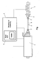
- the drawing figure shows a schematic representation of a test stand arrangement, for example an engine test stand, with an internal combustion engine as the test object 1, which is symbolized by its crankshaft.
- This test piece 1 is connected via a shaft 2 and an adapter flange 3 with an electric machine 4 for driving and / or loading of the test piece 1.
- the control and evaluation unit 5, which may also be parts of a still higher-level test stand automation system, also comprises a control arrangement 6 for the electric machine 4. While the test object 1 is constructed in real terms, components which can be connected thereto can be replaced by simulation, for which purpose at least one model is implemented for such connectable to the device under test components 1 in the control arrangement 6, from which model then the control request to the electric machine 4 is determined.
- the arrangement of connecting shaft 2 and electric machine 4 has a constant, predetermined moment of inertia.
- the mass and moment of inertia of the adapter flange 3 are selected so that the natural frequency of the system under test 1, adapter flange 3, connecting shaft 2 and electric machine 4 between the idling frequency and a partial load frequency of the specimen 1, i. preferably between about 20 and 60Hz.
- a realistic representation of the cyclical nonuniformity of the internal combustion engine as the test object 1 is possible since excited frequencies from the powertrain simulation or other models can be transmitted to the internal combustion engine.
- the wave 2 acts as a low-pass filter with respect to previous constructions upwardly shifted low-pass frequency.
- the safe and accurate compensation of the mechanical vibration system DUT 1, adapter flange 3, connecting shaft 2 and electric machine 4 in this frequency range, ie at a lying in the engine operating range mechanical natural frequency of the test bed, be supported by a suitable control strategy.
- the control arrangement 6 comprises, for example, a controller and an actual value calculation unit, which is arranged in a feedback branch.
- the actual value calculation unit a current actual value of the control and a prediction of an imminent, system delay-free actual value can be processed on the basis of the actual value of a previous work cycle to form a modified actual value which is fed back to the control.
- the connecting shaft 2 is designed as a constant velocity universal joint shaft. It has two constant velocity joints 7 at the ends of a steel tube 8 with adapted rigidity and torque transmission capability. Due to the constant velocity joints 7, the geometric alignment of the test piece 1 and the electric machine 4 is not so critical and can be performed very easily in comparison with conventionally used torsion bars. Also, one and the same shaft 2 can be used for many different test specimens 1, whereas so far for each specimen 1, the design of the shaft 2 recalculated and a specially tuned shaft 2 had to be installed.
- the drive and / or load unit 4 has the lowest possible moment of inertia for the good simulatory simulation of the repercussions of the components connected to the device under test 1, as well as preferably the largest possible ratio of torque to moment of inertia.
- the two features mentioned ensure the necessary high acceleration capability (deceleration), which is expressed by the value "revolutions per unit time" (rpm / sec), which is advantageously not less than 30,000 rpm / sec and from the nominal torque, the possible overload and the inertia mass of the machine is calculated.
- the electric machine 4 in particular its rotor, prepared for angle-synchronous, jerky, high torque loads. Measures for avoiding eddy currents and thus excessive heat development also contribute, in particular in the area of de (r) mounting rings of the electric machine 4.
- the electric machine 4 is designed as a three-phase three-phase machine, preferably as an asynchronous machine, a separately excited or permanently magnet-excited synchronous machine.
- the realistic imaging of the rotational irregularity in the entire speed band of an internal combustion engine as the test object 1 is possible.
- This is the basis for the transfer of SOP-oriented development and calibration tasks from the vehicle to the engine test bench (eg drivability, OBD, start / stop, ancillary engine development, structure-borne noise analyzes etc).
- SOP-oriented development and calibration tasks from the vehicle to the engine test bench (eg drivability, OBD, start / stop, ancillary engine development, structure-borne noise analyzes etc).
- OBD relevant rotational nonuniformity signal can be obtained as in the vehicle by the inventive test rig, which was previously not feasible on any engine test, as conventional test stand systems, in combination with conventional control, smooth this behavior.
- Driveability is the subjective feeling of a driver interacting with a vehicle.
- driving performance and consumption for example on the powertrain test bench, and of consumption and emissions on the chassis dynamometer.
- the tuning of driveability is performed almost exclusively in the vehicle based on subjective evaluations by test drivers. However, if satisfactory drivability tuning is not achieved in the vehicle, it will not be possible to prevent repetitive loops in the development process. A global, common optimum can only be found to be difficult due to the separate coordination of the development goals.
- the above problems can be circumvented. Thanks to the integration on the engine test bench, numerous coordination tasks can now be carried out earlier in the development process.
- the tuning of the test rig arrangement according to the invention to a natural frequency of the system between 10 Hz and 100 Hz, preferably between 20 Hz and 60 Hz, is advantageous since many drivability maneuvers cause vibrations in this range. For example, vibrations of the drivability maneuver "tip-in" (positive load stroke by the accelerator pedal) reach up to 40 Hz.
- the test rig arrangement according to the invention also allows the time-saving and material-saving investigation of questions on the effects of various connected components by the simulation of their reaction in said frequency range, such as starting and stopping, without having to perform experiments with a variety of real components.
- no expensive test vehicles or component prototypes are necessary, the representation of hardware changes or variants in a very short time is possible, other components can be replaced faster than in real vehicles, the tests are very well compared with each other, since development environment always remains constant, and If required, comprehensive measuring equipment can be used.
Landscapes
- Physics & Mathematics (AREA)
- General Physics & Mathematics (AREA)
- Chemical & Material Sciences (AREA)
- Engineering & Computer Science (AREA)
- Combustion & Propulsion (AREA)
- Testing Of Engines (AREA)
- Testing Of Devices, Machine Parts, Or Other Structures Thereof (AREA)
Description
- Die Erfindung betrifft eine Prüfstandsanordnung mit einem Prüfling, welcher durch eine Verbindungswelle mit Adapterflansch und Drehmomentmessflansch mit einer Elektromaschine für Antrieb und/oder Belastung des Prüflings verbunden ist, sowie mit einer Regelungsanordnung für die Elektromaschine für Antrieb und/oder Belastung des Prüflings, wobei die Anordnung aus Verbindungswelle und Antriebs- und Belastungsmaschine ein konstantes, vorgegebenes Trägheitsmoment aufweist.
- Steigende Kraftstoffpreise und gesetzliche Vorgaben in Bezug auf Emission und 002, in Kombination mit hohen Kundenerwartungen bzgl. Komfort, führt zu einem stetig wachsenden Bedarf in Hinblick auf kostenoptimierte Fahrzeuge mit hoch innovativen Antriebsträngen. Aus diesem Grund sind die Fahrzeughersteller mit der Herausforderung konfrontiert, hoch komplexe Antriebstranglösungen schnell und zielgerichtet zu entwickeln. Um diesen Herausforderungen gerecht zu werden, sind diverse Strategien entwickelt worden wobei sich das "Front Loading" des Entwicklungsprozesses, auf Basis des "Road-to-Lab-Math" Strategieansatzes, als Kernstrategie herauskristallisiert hat. Hier sollen Entwicklungsaufgäben, welche früher nur in teuren Prototypenumgebungen bearbeitet werden konnten, in frühe Prozessphasen transferiert werden, wie beispielsweise in Gschweitl K., Ellinger R., Loibner E.: "Werkzeuge und Methoden im Hybrid Entwicklungsprozess", 19. "Motor und Umwelt"-Konferenz, Graz 2007, in Schyr C., Gschweitl K.: "Methodische Validierung von hybriden Antriebsträngen". 2. Internationales Symposium für Entwicklungsmethodik, Darmstadt, 2007 oder in Beidl C., Rainer G., Schoeggl P., Martini E., Dener D.: "Enabling Future Powertrain Solutions by Innovative Simulation & Testing Toolchains". 32nd FISITA World Automaotive Congress, Munich, 2008, beschrieben ist. Die Prototypenumgebungen sollen durch Simulationsumgebungen ersetzt werden. Diese Strategie setzt aber voraus, dass dem Entwickler durchgängige Entwicklungsumgebungen zur Verfügung stehen, in denen er das Gesamtsystemverhalten Fahrzeug aber auch dessen Interaktion mit der Umgebung berücksichtigen kann.
- Um etwa Themen wie Fahrbarkeitskalibration qualitativ hochwertig auf den Motorenprüfstand verlagern zu können, muss man in der Lage sein Effekte abzubilden, die für den späteren Kundenkomfort relevant sind. Ein herkömmlicher Motorprüfstand für einen Verbrennungsmotor, der über eine Verbindungswelle mit einer Antriebs- und Belastungsmaschine verbunden ist, ist beispielsweise aus der
AT 9 782 U2 US 2002/0091471 A1 zeigt einen Motorprüfstand mit Verbrennungsmotor, Verbindungswelle und einer Antriebs- und Belastungsmaschine, deren Eigenfrequenz über 100Hz gelegt ist. Um Tests mit dieser Prüfstandsanordnung durchführen zu können ist eine Resonanzsteuereinheit vorgesehen, die Resonanz während des Tests unterdrückt. - Es war daher die Aufgabe der vorliegenden Erfindung, eine Prüfstandsanordnung anzugeben, insbesondere einen Motorenprüfstand, der unter Vermeidung der oben deutlich gewordenen Nachteile die Verbindung der Antriebstrang- und Fahrzeugsimulation mit dem realen fahrzeugspezifischen Verbrennungs- und Instationärverhaltens des Motors herstellen kann. Insbesondere sollte, was bislang nicht möglich war, die zyklische Ungleichförmigkeit des Verbrennungsmotors detailgetreu darstellbar sein und angeregte Frequenzen aus der Antriebstrangsimulation, bis zu 40Hz, auf den Verbrennungsmotor übertragen werden können.
- Zur Lösung dieser Aufgabe ist erfindungsgemäß vorgesehen, dass die Masse und das Trägheitsmoment des Adapterflansches derart gewählt ist, dass die Eigenfrequenz des Systems aus Prüfling, Adapterflansch, Verbindungswelle und Eektromaschine für Antrieb und/oder Belastung des Prüflings zwischen der Leerlauffrequenz und einer Teillastfrequenz des Prüflings liegt. Durch diese Systemauslegung sind nun beispielsweise die realistische Darstellung von "echten" Verbrennungsstößen mit Aussetzern oder der hybridrelevante Start/Stopp-Betrieb in Kombination mit hochentwickelter Fahrzeugsimulation auch am Prüfstand umsetzbar. Damit ist diese Prüfstandkonfiguration hervorragend für Arbeiten im Motor-& Antriebstrangbereich, die eine hohe Korrelation zum realen instationären Fahrzeugverhal-_ ten aufweisen müssen, geeignet.
- Ein besonders wichtiges Thema ist die Darstellung von Triebstrangschwingungen bis 40Hz mit der Möglichkeit der sicheren und genauen Ausregelung des mechanischen Schwingsystems Motor - Welle - Belastungseinheit in diesem Frequenzbereich, d.h. bei einer im Motorenbetriebsbereich liegenden mechanischen Eigenfrequenz des Prüfstandaufbaues. Gemäß einem vorteilhaften Ausführungsbeispiel der Erfindung ist daher vorgesehen, dass das Trägheitsmoment des Adapterflansches derart gewählt wird, dass die Eigenfrequenz des Systems zwischen 10 Hz und 100 Hz liegt, vorzugsweise zwischen 20 Hz und 60 Hz.
- Vorteilhafterweise ist die Verbindungswelle als Geichlaufgelenkwelle ausgeführt.
- Um die realen, instationären Rückwirkungen im Fahrzeugverhalten simulatorisch gut nachbilden zu können, ist eine Belastungseinheit notwendig, die sich durch niedrigste Eigenschwungmasse und hohe Verstellgeschwindigkeiten auszeichnet. Daher ist ein weiteres Ausführüngsbeispiel der Erfindung dadurch gekennzeichnet, dass die Elektromaschine für Antrieb und/oder Belastung des Prüflings ein möglichst geringes Trägheitsmoment aufweist.
- Vorteilhafterweise ist zusätzlich auch vorgesehen, dass die Elektromaschine für Antrieb und/oder Belastung des Prüflings ein möglichst großes Verhältnis aus Drehmoment zu Trägheitsmoment aufweist. Die beiden genannten Merkmale sind dafür verantwortlich, dass die Elektromaschine für Antrieb und/oder Belastung des Prüflings hohe Beschleunigungsfähigkeit (Abbremsung) besitzt.
- Gemäß einer besonders zweckmäßigen Ausgestaltung der Erfindung ist die Elektromaschine für Antrieb und/oder Belastung des Prüflings, insbesondere deren Rotor, für winkelsynchrone, stoßartige, hohe Drehmomentbelastungen vorbereitet.
- Besonders gut können die oben genannten Anforderungen umgesetzt werden, wenn die Antriebs- und Belastungsmaschine als 3-Phasen-gespeiste Drehstrommaschine, vorzugsweise als Asynchronmaschine, fremderregte oder permanentmagneterregte Synchronmaschine, ausgeführt ist.
- In der nachfolgenden Beschreibung soll die Erfindung anhand eines bevorzugten Ausführungsbeispiels und der beigefügten Zeichnung näher erläutert werden.
- Die Zeichnungsfigur zeigt in schematischer Darstellung eine Prüfstandsanordnung, beispielsweise einen Motorenprüfstand, mit einer Verbrennungskraftmaschine als Prüfling 1, die durch deren Kurbelwelle symbolisiert ist. Dieser Prüfling 1 ist über eine Welle 2 und einen Adapterflansch 3 mit einer Elektromaschine 4 für Antrieb und/oder Belastung des Prüflings 1 verbunden. Die Steuer- und Auswerte-Einheit 5, welche auch Teile eines noch übergeordneten Prüfstandsautomatisierungssystems sein kann, umfasst auch eine Regelungsanordnung 6 für die Elektromaschine 4. Während der Prüfling 1 real aufgebaut ist, können daran anschließbare Komponenten durch Simulation ersetzt werden, wofür zumindest ein Modell für derartige, an den Prüfling 1 anschließbare Komponenten in der Regelungsanordnung 6 implementiert ist, aus welchem Modell dann die Regelanforderung an die Elektromaschine 4 ermittelt wird.
- Die Anordnung aus Verbindungswelle 2 und Elektromaschine 4 weist ein konstantes, vorgegebenes Trägheitsmoment auf. Zusätzlich sind die Masse und das Trägheitsmoment des Adapterflansches 3 derart gewählt, dass die Eigenfrequenz des Systems aus Prüfling 1, Adapterflansch 3, Verbindungswelle 2 und Elektromaschine 4 zwischen der Leerlauffrequenz und einer Teillastfrequenz des Prüflings 1, d.h. vorzugsweise zwischen etwa 20 und 60Hz, liegt. In diesem Frequenzbereich ist eine realistische Darstellung von die zyklische Ungleichförmigkeit des Verbrennungsmotors als Prüfling 1 möglich, da angeregte Frequenzen aus der Antriebstrangsimulation oder anderen Modellen auf den Verbrennungsmotor übertragen werden können. Die Welle 2 wirkt dabei wie ein Tiefpass-Filter mit gegenüber bisherigen Aufbauten nach oben verschobener Tiefpass-Frequenz.
- Vorteilhafterweise kann die sichere und genaue Ausregelung des mechanischen Schwingsystems Prüfling 1, Adapterflansch 3, Verbindungswelle 2 und Elektromaschine 4 in diesem Frequenzbereich, d.h. bei einer im Motorenbetriebsbereich liegenden mechanischen Eigenfrequenz des Prüfstandaufbaues, durch eine geeignete Regelungsstrategie unterstützt werden. Die Regelungsanordnung 6 umfasst dazu beispielsweise einen Regler und eine Istwertberechnungseinheit, die in einem Feedback-Zweig angeordnet ist. In der Istwertberechnungseinheit sind ein aktueller Istwert der Regelung und eine Vorhersage eines bevorstehenden, systemverzögerungsfreien Istwertes auf der Grundlage des Istwertes eines vorherigen Arbeitszyklus zu einem modifizierten Istwert verarbeitbar, der der Regelung rückgeführt wird.
- Vorteilhafterweise ist die Verbindungswelle 2 als Gleichlaufgelenkwelle ausgeführt. Sie weist zwei Gleichlaufgelenke 7 an den Enden eines Stahlrohres 8 mit angepasster Steifigkeit und Momentenübertragungsfähigkeit auf. Aufgrund der Gleichlaufgelenke 7 ist die geometrische Ausrichtung von Prüfling 1 und Elektromaschine 4 nicht so kritisch und kann im Vergleich mit herkömmlich verwendeten Drehstäben sehr einfach durchgeführt werden. Auch ist ein und dieselbe Welle 2 für viele unterschiedliche Prüflinge 1 verwendbar, während bislang für jeden Prüfling 1 die Auslegung der Welle 2 neu berechnet und eine speziell abgestimmte Welle 2 verbaut werden musste.
- Die Antriebs- und/oder Belastungseinheit 4 weist für die gute simulatorische Nachbildung der Rückwirkungen der am Prüfling 1 angeschlossenen Komponenten ein möglichst geringes Trägheitsmoment auf, ebenso wie vorzugsweise ein möglichst großes Verhältnis aus Drehmoment zu Trägheitsmoment. Die beiden genannten Merkmale gewährleisten die notwendige hohe Beschleunigungsfähigkeit (Abbremsung), welche durch den Wert "Umdrehungen pro Zeiteinheit pro Zeiteinheit" (rpm/sec) ausgedrückt, der vorteilhafterweise nicht unter 30.000 rpm/sec liegt und sich aus dem Nennmoment, der möglichen Überlast und der Trägheitsmasse der Maschine errechnet.
- Gemäß einer besonders zweckmäßigen Ausgestaltung der Erfindung ist die Elektromaschine 4, insbesondere deren Rotor, für winkelsynchrone, stoßartige, hohe Drehmomentbelastungen vorbereitet. Auch Maßnahmen zur Vermeidung von Wirbelströmen und damit übermäßiger Hitzeentwicklung tragen dazu bei, insbesondere im Bereich de(r) Montageringe der Elektromaschine 4.
- Besonders gut können die oben genannten Anforderungen umgesetzt werden, wenn die Elektromaschine 4 als 3-Phasen-gespeiste Drehstrommaschine, vorzugsweise als Asynchronmaschine, fremderregte oder permanentmagneterregte Synchronmaschine, ausgeführt ist.
- Mit der erfindungsgemäßen Prüfstandsanordnung ist beispielsweise die realistische Abbildung der Drehungleichförmigkeit im gesamten Drehzahlband eines Verbrennungsmotors als Prüfling 1 möglich. Das ist die Basis für die Übertragung von SOP orientierten Entwicklungs- und Kalibrationsaufgaben vom Fahrzeug auf den Motorenprüfstand (z.B. Fahrbarkeit, OBD, Start/Stop, Nebenaggregatetriebentwicklung, Körperschallanalysen etc). Dies betrifft auch die Aussetzererkennung von Ottomotoren, bei welcher durch die erfindungsgemäße Prüfstandsanordnung jetzt das OBD relevante Drehungleichförmigkeitssignal wie im Fahrzeug erhalten werden kann, was bislang auf keinem Motorenprüfstand realisierbar war, da konventionelle Prüfstandsysteme, in Kombination mit konventioneller Regelung, dieses Verhalten glätten. Und das besonders bei Hybridantrieben wesentliche Verhalten von Mehrmassenschwungrädern kann simuliert werden, ohne auf die Verfügbarkeit von Prototypen angewiesen zu sein, welches durch die zum Motor hin verstärkte Drehungleichförmigkeit gekennzeichnet ist. Mit Hilfe der erfindungsgemäßen Merkmale können nun die Auswirkungen von Mehrmassenschwungrädern auf den Verbrennungsmotor systematisch und hocheffizient untersucht werden.
- Ebenso müssen für Aufgaben wie die qualitativ hochwertig auf den Motorenprüfstand zu verlagernde Fahrbarkeitskalibration Effekte abgebildet werden können, die für den späteren Kundenkomfort relevant sind. Als Fahrbarkeit wird das subjektive Empfinden eines Fahrers bei Wechselwirkung mit einem Fahrzeug bezeichnet. Im Antriebsstrangentwicklungsprozess werden standardmäßig die Entwicklungsziele Fahrleistung, Verbrauch, Emissionen und Fahrbarkeit unterschieden. Die Abstimmung und Optimierung der jeweiligen Ziele erfolgt meist auf unterschiedlichen Plattformen: Fahrleistung und Verbrauch etwa am Antriebsstrangsprüfstand, jene von Verbrauch und Emissionen am Rollenprüfstand. Die Abstimmung der Fahrbarkeit wird praktisch ausschließlich im Fahrzeug, basierend auf subjektiven Bewertungen von Testfahrern, durchgeführt. Wird im Fahrzeug aber keine zufriedenstellende Fahrbarkeitsabstimmung erzielt, so sind Wiederholungsschleifen im Entwicklungsprozess nicht zu verhindern. Ein globales, gemeinsames Optimum kann auf Grund der getrennten Abstimmung der Entwicklungsziele nur erschwert gefunden werden.
- Durch Einsatz von Methoden zur Simulation sowie zur objektiven Bewertung der Fahrbarkeit im Antriebsstrangentwicklungsprozess können obige Probleme umgangen werden. Durch die Integration am Motorenprüfstand können nun zahlreiche Abstimmungsaufgaben bereits früher im Entwicklungsprozess durchgeführt werden. Auch hier ist die erfindungsgemäße Abstimmung der Prüfstandsanordnung auf eine Eigenfrequenz des Systems zwischen 10 Hz und 100 Hz, vorzugsweise zwischen 20 Hz und 60 Hz, von Vorteil, da viele Fahrbarkeitsmanöver in diesem Bereich liegende Schwingungen hervorrufen. Beispielsweise erreichen Schwingungen des Fahrbarkeitsmanövers "Tip In" (positiver Lastschlag durch das Fahrpedal) bis zu 40Hz.
- Auch gestattet die erfindungsgemäße Prüfstandsanordnung die zeit- und materialsparende Untersuchung von Fragen zur Auswirkung verschiedenster angeschlossener Komponenten durch die Simulation von deren Rückwirkung im genannten Frequenzbereich, etwa bei Starten und Stoppen, ohne Versuche mit einer Vielzahl von realen Komponenten durchführen zu müssen. Dabei sind keine teuren Versuchsfahrzeuge oder Komponentenprototypen notwendig, ist die Darstellung von Hardware-Änderungen oder Varianten in sehr kurzer Zeit möglich, können andere Bauteile schneller getauscht werden als in realen Fahrzeugen, sind die Tests sehr gut untereinander vergleichbar, da Entwicklungsumgebung immer konstant bleibt, und kann je nach Bedarf umfassendes Messequipment angewendet werden.
Claims (7)
- Prüfstandsanordnung mit einem Prüfling (1), welcher durch eine Verbindungswelle (2) mit Adapterflansch (3) mit einer Elektromaschine (4) für Antrieb und/oder Belastung des Prüflings (1) verbunden ist, sowie mit einer Regelungsanordnung für die Elektromaschine (4) für Antrieb und/oder Belastung des Prüflings (1), wobei die Anordnung aus Verbindungswelle (2) und Antriebs- und Belastungsmaschine (4) ein konstantes, vorgegebenes Trägheitsmoment aufweist, dadurch gekennzeichnet, dass die Masse und das Trägheitsmoment des Adapterflansches (3) derart gewählt ist, dass die Eigenfrequenz des Systems aus Prüfling (1), Adapterflänsch (3), Verbindungswelle (2) und Elektromaschine (4) für Antrieb und/oder Belastung des Prüflings (1) zwischen der Leerlauffrequenz und einer Teillastfrequenz des Prüflings (1) liegt.
- Prüfstandsanordnung nach Anspruch 1, dadurch gekennzeichnet, dass das Trägheitsmoment des Adapterflansches (3) derart gewählt wird, dass die Eigenfrequenz des Systems (1, 2, 3, 4) zwischen 10 Hz und 100 Hz liegt, vorzugsweise zwischen 20 Hz und 60 Hz.
- Prüfstandsanordnung nach Anspruch 1 oder 2, dadurch gekennzeichnet, dass die Verbindungswelle (2) als Gleichlaufgelenkwelle ausgeführt ist.
- Prüfstandsanordnung nach einem der Ansprüche 1 bis 3, dadurch gekennzeichnet, dass die Elektromaschine (4) für Antrieb und/oder Belastung des Prüflings (1) ein möglichst geringes Trägheitsmoment aufweist.
- Prüfstandsanordnung nach Anspruch 4, dadurch gekennzeichnet, dass die Elektromaschine (4) für Antrieb und/oder Belastung des Prüflings (1) ein möglichst großes Verhältnis aus Drehmoment zu Trägheitsmoment aufweist.
- Prüfstandsanordnung nach Anspruch 4 oder 5, dadurch gekennzeichnet, dass die Elektromaschine (4) für Antrieb und/oder Belastung des Prüflings (1), insbesondere deren Rotor, für winkelsynchrone, stoßartige, hohe Drehmomentbelastungen vorbereitet ist.
- Prüfstandsanordnung nach einem der Ansprüche 4 bis 6, dadurch gekennzeichnet, dass die Antriebs- und Belastungsmaschine (4) als 3-Phasen-gespeiste Drehstrommaschine, vorzugsweise als Asynchronmaschine, fremderregte oder permanentmagneterregte Synchronmaschine, ausgeführt ist.
Priority Applications (1)
| Application Number | Priority Date | Filing Date | Title |
|---|---|---|---|
| PL10164599T PL2264422T3 (pl) | 2009-06-16 | 2010-06-01 | Układ stanowiska badawczego |
Applications Claiming Priority (1)
| Application Number | Priority Date | Filing Date | Title |
|---|---|---|---|
| AT0036909U AT10812U3 (de) | 2009-06-16 | 2009-06-16 | Prüfstandsanordnung |
Publications (3)
| Publication Number | Publication Date |
|---|---|
| EP2264422A2 EP2264422A2 (de) | 2010-12-22 |
| EP2264422A3 EP2264422A3 (de) | 2014-07-02 |
| EP2264422B1 true EP2264422B1 (de) | 2015-09-09 |
Family
ID=40935217
Family Applications (1)
| Application Number | Title | Priority Date | Filing Date |
|---|---|---|---|
| EP10164599.2A Active EP2264422B1 (de) | 2009-06-16 | 2010-06-01 | Prüfstandsanordnung |
Country Status (7)
| Country | Link |
|---|---|
| US (1) | US8418542B2 (de) |
| EP (1) | EP2264422B1 (de) |
| JP (1) | JP5150680B2 (de) |
| CN (1) | CN101957262B (de) |
| AT (1) | AT10812U3 (de) |
| HU (1) | HUE028256T2 (de) |
| PL (1) | PL2264422T3 (de) |
Families Citing this family (19)
| Publication number | Priority date | Publication date | Assignee | Title |
|---|---|---|---|---|
| US8590369B2 (en) * | 2010-12-23 | 2013-11-26 | Horiba Instruments, Inc. | Vehicle drivetrain test stand and method of controlling same |
| AT510378B1 (de) * | 2011-12-15 | 2012-09-15 | Avl List Gmbh | Verfahren und prüfstand zum testen eines startermotors |
| AT512186B1 (de) * | 2012-04-18 | 2013-06-15 | Avl List Gmbh | Motorenprüfstand |
| DE102014226515B4 (de) * | 2014-12-19 | 2020-02-13 | Zf Friedrichshafen Ag | Getriebeprüfstand |
| CN104656556B (zh) * | 2015-01-23 | 2017-10-13 | 清能德创电气技术(北京)有限公司 | 一种基于参考模型自适应的惯量比调节方法 |
| KR101660406B1 (ko) * | 2015-07-13 | 2016-09-30 | 재단법인경북테크노파크 | 모터의 nvh 성능시험장치 |
| CN105258949A (zh) * | 2015-10-03 | 2016-01-20 | 李志勇 | 一种发动机安装支架及其工艺方法 |
| KR101962849B1 (ko) * | 2015-11-10 | 2019-03-27 | 이래에이엠에스 주식회사 | 차량용 드라이브 샤프트의 다목적 시험장치 |
| KR101919549B1 (ko) * | 2016-12-05 | 2018-11-16 | 코리아테스팅 주식회사 | 제어 안정성 및 신뢰성이 향상된 하이브리드 서보 액추에이터 |
| KR101921302B1 (ko) * | 2016-12-05 | 2018-11-22 | 코리아테스팅 주식회사 | 기계적인 트리거 기능을 이용한 응답성능 개선 하이브리드 서보 액추에이터 |
| AT519261B1 (de) * | 2016-12-05 | 2018-05-15 | Avl List Gmbh | Verfahren und Prüfstand zum Durchführen eines Prüflaufs mit einem Antriebsstrang |
| CN106706327A (zh) * | 2017-01-19 | 2017-05-24 | 浙江大学 | 一种发动机燃烧过程实验研究装置 |
| AT520185B1 (de) * | 2017-12-04 | 2019-02-15 | Avl List Gmbh | Prüfstand und Verfahren zur Durchführung eines Prüfversuchs |
| CN108087155B (zh) * | 2017-12-19 | 2024-02-09 | 西安航天动力研究所 | 一种大流量液体输送系统频率特性试验系统的试验方法 |
| AT522555B1 (de) * | 2019-05-14 | 2020-12-15 | Tectos Gmbh | Verfahren zur echtzeit-analyse innermotorischer prozesse |
| AT522354B1 (de) * | 2019-08-12 | 2020-10-15 | Avl List Gmbh | Verfahren zum Betreiben eines Prüfstands |
| US11790126B2 (en) | 2019-12-19 | 2023-10-17 | Caterpillar Inc. | Method and system for internal combustion engine simulation |
| CN111044195B (zh) * | 2019-12-28 | 2024-07-23 | 烟台大学 | 应用于内燃机浮动缸套摩擦试验机的模拟点火定时装置 |
| CN115372001B (zh) * | 2021-05-20 | 2025-11-25 | 中国航发商用航空发动机有限责任公司 | 一种试车台现场交互方法和系统 |
Family Cites Families (31)
| Publication number | Priority date | Publication date | Assignee | Title |
|---|---|---|---|---|
| DE660989C (de) * | 1934-04-17 | 1938-06-08 | Versuchsanstalt Fuer Luftfahrt | Motorenpruefstand mit einem federnd gegen das Fundament abgestuetzten Motortraeger |
| AT263089B (de) * | 1965-11-23 | 1968-07-10 | Telefunken Patent | Schaltungsanordnung mit Kapazitätsdioden |
| US4382388A (en) * | 1979-10-31 | 1983-05-10 | Kabushiki Kaisha Ono Sokki | Dynamometer road simulating method and system |
| US4466294A (en) * | 1981-12-31 | 1984-08-21 | Edi | Transient driving cycle simulator test system |
| US4899595A (en) * | 1989-02-17 | 1990-02-13 | Warsaw Arthur J | Modular dynamometer with extended testing range |
| US5452605A (en) * | 1991-02-08 | 1995-09-26 | Clayton Industries | Dynamometer for simulating the inertial and road load forces encountered by motor vehicles |
| JPH0523094U (ja) * | 1991-09-11 | 1993-03-26 | 株式会社明電舎 | 自動車用エンジンのテストスタンド |
| US5375460A (en) * | 1993-04-09 | 1994-12-27 | Clayton Industries | Method and apparatus for testing motor vehicles under simulated road conditions |
| US5445013A (en) * | 1993-08-30 | 1995-08-29 | Clayton Industries | Dynamometer for simulating the inertial and road load forces encountered by motor vehicles and method |
| US5465612A (en) * | 1994-06-16 | 1995-11-14 | Clayton Industries | Method and apparatus for testing motor vehicles under simulated road conditions |
| EP0704689B1 (de) * | 1994-09-30 | 2003-04-16 | AVL List GmbH | Verfahren zur Trägheitsmomentbestimmung |
| JPH09178616A (ja) | 1995-12-25 | 1997-07-11 | Meidensha Corp | 車両用試験装置 |
| JP3424458B2 (ja) * | 1996-09-27 | 2003-07-07 | トヨタ自動車株式会社 | 車両運転性評価装置 |
| JP3405924B2 (ja) | 1998-07-21 | 2003-05-12 | トヨタ自動車株式会社 | 負荷伝達装置 |
| JP3405925B2 (ja) * | 1998-07-22 | 2003-05-12 | トヨタ自動車株式会社 | エンジンの試験装置 |
| JP4020513B2 (ja) * | 1998-09-30 | 2007-12-12 | トヨタ自動車株式会社 | 原動機の試験装置 |
| US6360591B1 (en) * | 2000-03-02 | 2002-03-26 | Burke E. Porter Machinery Company | Method of controlling a chassis dynamometer |
| US6651493B2 (en) * | 2000-05-04 | 2003-11-25 | Hicklin Engineering, L.C. | Torque converter dynamometer and method of using same |
| JP3918435B2 (ja) * | 2001-01-11 | 2007-05-23 | 株式会社明電舎 | 自動車部品の試験装置 |
| JP2003207424A (ja) * | 2002-01-09 | 2003-07-25 | Meidensha Corp | エンジンベンチシステム |
| US6860145B2 (en) * | 2003-04-14 | 2005-03-01 | Power Test, Inc. | Chassis dynamometer |
| EP1721123A4 (de) * | 2004-02-03 | 2011-01-19 | Drag Tag Pty Ltd | Fahrzeuglenk-messvorrichtung |
| JP4207810B2 (ja) * | 2004-03-11 | 2009-01-14 | 神鋼電機株式会社 | Pmモータの評価試験装置 |
| AT7073U3 (de) * | 2004-05-24 | 2005-05-25 | Avl List Gmbh | Prüfstand für brennkraftmaschinen |
| JP2006271057A (ja) | 2005-03-23 | 2006-10-05 | Toshiba Mitsubishi-Electric Industrial System Corp | 永久磁石同期電動機の回転子 |
| JP4837940B2 (ja) * | 2005-05-18 | 2011-12-14 | 株式会社エー・アンド・デイ | 回転型分力計測装置 |
| JP4788543B2 (ja) * | 2006-09-19 | 2011-10-05 | 株式会社明電舎 | エンジンベンチシステムのパラメータ推定装置 |
| JP4788627B2 (ja) * | 2007-02-20 | 2011-10-05 | 株式会社明電舎 | エンジンベンチシステムのパラメータ推定装置 |
| JP4333767B2 (ja) * | 2007-04-03 | 2009-09-16 | 株式会社デンソー | 車両制御装置 |
| AT9782U3 (de) * | 2007-10-11 | 2008-10-15 | Avl List Gmbh | Drehmoment-messflansch |
| US7926336B2 (en) * | 2008-09-04 | 2011-04-19 | Vickio Jr Louis P | Dynamometer |
-
2009
- 2009-06-16 AT AT0036909U patent/AT10812U3/de not_active IP Right Cessation
-
2010
- 2010-06-01 EP EP10164599.2A patent/EP2264422B1/de active Active
- 2010-06-01 HU HUE10164599A patent/HUE028256T2/en unknown
- 2010-06-01 PL PL10164599T patent/PL2264422T3/pl unknown
- 2010-06-12 CN CN2010102130675A patent/CN101957262B/zh active Active
- 2010-06-15 US US12/801,581 patent/US8418542B2/en active Active
- 2010-06-15 JP JP2010136141A patent/JP5150680B2/ja active Active
Also Published As
| Publication number | Publication date |
|---|---|
| US20110000291A1 (en) | 2011-01-06 |
| JP2011002455A (ja) | 2011-01-06 |
| CN101957262A (zh) | 2011-01-26 |
| EP2264422A3 (de) | 2014-07-02 |
| CN101957262B (zh) | 2012-07-04 |
| AT10812U3 (de) | 2010-03-15 |
| EP2264422A2 (de) | 2010-12-22 |
| US8418542B2 (en) | 2013-04-16 |
| PL2264422T3 (pl) | 2016-04-29 |
| JP5150680B2 (ja) | 2013-02-20 |
| HUE028256T2 (en) | 2016-12-28 |
| AT10812U2 (de) | 2009-10-15 |
Similar Documents
| Publication | Publication Date | Title |
|---|---|---|
| EP2264422B1 (de) | Prüfstandsanordnung | |
| EP2264421B1 (de) | Prüfstandsanordnung | |
| AT517689B1 (de) | Verfahren zum Erstellen eines Prüfversuchs | |
| EP1456621B1 (de) | Verfahren zur leistungsermittlung, messvorrichtung und leistungspruefstand fuer einen pruefling | |
| EP2321708B1 (de) | Verfahren und regelanordnung zur regelung einer regelstrecke mit sich wiederholendem arbeitszyklus | |
| DE112007003038B4 (de) | Antriebsstrang | |
| DE102007016420B4 (de) | Prüfstand und Verfahren zum Überprüfen eines Antriebsstrangs | |
| EP2766590A1 (de) | Verfahren und vorrichtung zum erkennen von drehzahl-/drehmomentschwankungen in einer antriebsvorrichtung | |
| AT508909A4 (de) | Verfahren und einrichtung zur regelung einer prüfstandsanordnung | |
| CN110006663A (zh) | 前置横驱混合动力总成的整车传动系扭振分析方法及系统 | |
| EP3059569A2 (de) | Verfahren zur teilphysikalischen echtzeitsimulation | |
| WO2008040282A1 (de) | Antriebsstrang | |
| EP2019303A1 (de) | Verfahren zum Auswuchten eines Fahrzeugrades | |
| DE102018218622A1 (de) | Verfahren zum Re-Integrieren eines Verbrennungsmotors in einen Antriebsstrang eines Fahrzeuges | |
| EP1382956A2 (de) | Verfahren zur Simulation des Fahrverhaltens von Fahrzeugen | |
| EP1333268A2 (de) | Verfahren und Vorrichtung zum Prüfen eines Fahrzeug-Antriebsstranges | |
| DE102015120263B4 (de) | Verfahren zur Verschleißbestimmung, Messgerät, Steuervorrichtung dazu sowie Antriebsvorrichtung umfassend die Steuervorrichtung | |
| DE10162787B4 (de) | Verfahren zur Leistungsermittlung und Leistungsprüfstand für einen Prüfling | |
| DE10038281A1 (de) | Verfahren und Vorrichtung zur Reduktion von Schwingungen in einem Antriebssystem, sowie Steuereinrichtung für ein Antriebssystem | |
| EP1574835B1 (de) | Verfahren und Steuergerät zum Bereinigen eines Drehzahlsignals | |
| DE102012000836A1 (de) | Getriebeprüfstandeinrichtung für Getriebe, insbesondere für Windkraftanlagen, mit einem im Antriebsstrang integrierten Generator | |
| EP3279633B1 (de) | Prüfvorrichtung zur prüfung oder erprobung eines prüfgegenstands | |
| DE102018102202A1 (de) | Vorrichtung und Verfahren zur Zustandsüberwachung einer Elastomerkupplung oder eines Zweimassenschwungrades oder eines Torsionsdämpfers | |
| AT523048B1 (de) | Vorrichtung, Referenzfahrzeug mit einer Vorrichtung und Verfahren zur Bewertung und/oder Kalibrierung eines Prüfstands | |
| Pexa et al. | Dynamic measuring of performance parameters for vehicles engines |
Legal Events
| Date | Code | Title | Description |
|---|---|---|---|
| PUAI | Public reference made under article 153(3) epc to a published international application that has entered the european phase |
Free format text: ORIGINAL CODE: 0009012 |
|
| AK | Designated contracting states |
Kind code of ref document: A2 Designated state(s): AL AT BE BG CH CY CZ DE DK EE ES FI FR GB GR HR HU IE IS IT LI LT LU LV MC MK MT NL NO PL PT RO SE SI SK SM TR |
|
| AX | Request for extension of the european patent |
Extension state: BA ME RS |
|
| PUAL | Search report despatched |
Free format text: ORIGINAL CODE: 0009013 |
|
| AK | Designated contracting states |
Kind code of ref document: A3 Designated state(s): AL AT BE BG CH CY CZ DE DK EE ES FI FR GB GR HR HU IE IS IT LI LT LU LV MC MK MT NL NO PL PT RO SE SI SK SM TR |
|
| AX | Request for extension of the european patent |
Extension state: BA ME RS |
|
| RIC1 | Information provided on ipc code assigned before grant |
Ipc: G01M 15/04 20060101ALI20140527BHEP Ipc: G01M 15/02 20060101AFI20140527BHEP |
|
| 17P | Request for examination filed |
Effective date: 20140829 |
|
| RBV | Designated contracting states (corrected) |
Designated state(s): AL AT BE BG CH CY CZ DE DK EE ES FI FR GB GR HR HU IE IS IT LI LT LU LV MC MK MT NL NO PL PT RO SE SI SK SM TR |
|
| REG | Reference to a national code |
Ref country code: DE Ref legal event code: R079 Ref document number: 502010010233 Country of ref document: DE Free format text: PREVIOUS MAIN CLASS: G01M0015020000 Ipc: G01M0013020000 |
|
| RIC1 | Information provided on ipc code assigned before grant |
Ipc: G01M 15/02 20060101ALI20150122BHEP Ipc: G01M 13/02 20060101AFI20150122BHEP Ipc: G01M 15/04 20060101ALI20150122BHEP |
|
| GRAP | Despatch of communication of intention to grant a patent |
Free format text: ORIGINAL CODE: EPIDOSNIGR1 |
|
| INTG | Intention to grant announced |
Effective date: 20150410 |
|
| GRAS | Grant fee paid |
Free format text: ORIGINAL CODE: EPIDOSNIGR3 |
|
| GRAA | (expected) grant |
Free format text: ORIGINAL CODE: 0009210 |
|
| AK | Designated contracting states |
Kind code of ref document: B1 Designated state(s): AL AT BE BG CH CY CZ DE DK EE ES FI FR GB GR HR HU IE IS IT LI LT LU LV MC MK MT NL NO PL PT RO SE SI SK SM TR |
|
| REG | Reference to a national code |
Ref country code: GB Ref legal event code: FG4D Free format text: NOT ENGLISH |
|
| REG | Reference to a national code |
Ref country code: AT Ref legal event code: REF Ref document number: 748514 Country of ref document: AT Kind code of ref document: T Effective date: 20150915 Ref country code: CH Ref legal event code: EP |
|
| REG | Reference to a national code |
Ref country code: IE Ref legal event code: FG4D Free format text: LANGUAGE OF EP DOCUMENT: GERMAN |
|
| REG | Reference to a national code |
Ref country code: DE Ref legal event code: R096 Ref document number: 502010010233 Country of ref document: DE |
|
| REG | Reference to a national code |
Ref country code: SE Ref legal event code: TRGR |
|
| REG | Reference to a national code |
Ref country code: NL Ref legal event code: MP Effective date: 20150909 |
|
| PG25 | Lapsed in a contracting state [announced via postgrant information from national office to epo] |
Ref country code: GR Free format text: LAPSE BECAUSE OF FAILURE TO SUBMIT A TRANSLATION OF THE DESCRIPTION OR TO PAY THE FEE WITHIN THE PRESCRIBED TIME-LIMIT Effective date: 20151210 Ref country code: LT Free format text: LAPSE BECAUSE OF FAILURE TO SUBMIT A TRANSLATION OF THE DESCRIPTION OR TO PAY THE FEE WITHIN THE PRESCRIBED TIME-LIMIT Effective date: 20150909 Ref country code: FI Free format text: LAPSE BECAUSE OF FAILURE TO SUBMIT A TRANSLATION OF THE DESCRIPTION OR TO PAY THE FEE WITHIN THE PRESCRIBED TIME-LIMIT Effective date: 20150909 Ref country code: LV Free format text: LAPSE BECAUSE OF FAILURE TO SUBMIT A TRANSLATION OF THE DESCRIPTION OR TO PAY THE FEE WITHIN THE PRESCRIBED TIME-LIMIT Effective date: 20150909 Ref country code: NO Free format text: LAPSE BECAUSE OF FAILURE TO SUBMIT A TRANSLATION OF THE DESCRIPTION OR TO PAY THE FEE WITHIN THE PRESCRIBED TIME-LIMIT Effective date: 20151209 |
|
| REG | Reference to a national code |
Ref country code: LT Ref legal event code: MG4D |
|
| PG25 | Lapsed in a contracting state [announced via postgrant information from national office to epo] |
Ref country code: ES Free format text: LAPSE BECAUSE OF FAILURE TO SUBMIT A TRANSLATION OF THE DESCRIPTION OR TO PAY THE FEE WITHIN THE PRESCRIBED TIME-LIMIT Effective date: 20150909 Ref country code: HR Free format text: LAPSE BECAUSE OF FAILURE TO SUBMIT A TRANSLATION OF THE DESCRIPTION OR TO PAY THE FEE WITHIN THE PRESCRIBED TIME-LIMIT Effective date: 20150909 |
|
| PG25 | Lapsed in a contracting state [announced via postgrant information from national office to epo] |
Ref country code: NL Free format text: LAPSE BECAUSE OF FAILURE TO SUBMIT A TRANSLATION OF THE DESCRIPTION OR TO PAY THE FEE WITHIN THE PRESCRIBED TIME-LIMIT Effective date: 20150909 |
|
| PG25 | Lapsed in a contracting state [announced via postgrant information from national office to epo] |
Ref country code: CZ Free format text: LAPSE BECAUSE OF FAILURE TO SUBMIT A TRANSLATION OF THE DESCRIPTION OR TO PAY THE FEE WITHIN THE PRESCRIBED TIME-LIMIT Effective date: 20150909 Ref country code: SK Free format text: LAPSE BECAUSE OF FAILURE TO SUBMIT A TRANSLATION OF THE DESCRIPTION OR TO PAY THE FEE WITHIN THE PRESCRIBED TIME-LIMIT Effective date: 20150909 Ref country code: IS Free format text: LAPSE BECAUSE OF FAILURE TO SUBMIT A TRANSLATION OF THE DESCRIPTION OR TO PAY THE FEE WITHIN THE PRESCRIBED TIME-LIMIT Effective date: 20160109 Ref country code: EE Free format text: LAPSE BECAUSE OF FAILURE TO SUBMIT A TRANSLATION OF THE DESCRIPTION OR TO PAY THE FEE WITHIN THE PRESCRIBED TIME-LIMIT Effective date: 20150909 |
|
| PG25 | Lapsed in a contracting state [announced via postgrant information from national office to epo] |
Ref country code: RO Free format text: LAPSE BECAUSE OF FAILURE TO SUBMIT A TRANSLATION OF THE DESCRIPTION OR TO PAY THE FEE WITHIN THE PRESCRIBED TIME-LIMIT Effective date: 20150909 Ref country code: PT Free format text: LAPSE BECAUSE OF FAILURE TO SUBMIT A TRANSLATION OF THE DESCRIPTION OR TO PAY THE FEE WITHIN THE PRESCRIBED TIME-LIMIT Effective date: 20160111 |
|
| REG | Reference to a national code |
Ref country code: DE Ref legal event code: R097 Ref document number: 502010010233 Country of ref document: DE |
|
| REG | Reference to a national code |
Ref country code: FR Ref legal event code: PLFP Year of fee payment: 7 |
|
| PLBE | No opposition filed within time limit |
Free format text: ORIGINAL CODE: 0009261 |
|
| STAA | Information on the status of an ep patent application or granted ep patent |
Free format text: STATUS: NO OPPOSITION FILED WITHIN TIME LIMIT |
|
| 26N | No opposition filed |
Effective date: 20160610 |
|
| PG25 | Lapsed in a contracting state [announced via postgrant information from national office to epo] |
Ref country code: DK Free format text: LAPSE BECAUSE OF FAILURE TO SUBMIT A TRANSLATION OF THE DESCRIPTION OR TO PAY THE FEE WITHIN THE PRESCRIBED TIME-LIMIT Effective date: 20150909 Ref country code: SI Free format text: LAPSE BECAUSE OF FAILURE TO SUBMIT A TRANSLATION OF THE DESCRIPTION OR TO PAY THE FEE WITHIN THE PRESCRIBED TIME-LIMIT Effective date: 20150909 |
|
| REG | Reference to a national code |
Ref country code: HU Ref legal event code: AG4A Ref document number: E028256 Country of ref document: HU |
|
| PG25 | Lapsed in a contracting state [announced via postgrant information from national office to epo] |
Ref country code: BE Free format text: LAPSE BECAUSE OF NON-PAYMENT OF DUE FEES Effective date: 20160630 |
|
| PG25 | Lapsed in a contracting state [announced via postgrant information from national office to epo] |
Ref country code: MC Free format text: LAPSE BECAUSE OF FAILURE TO SUBMIT A TRANSLATION OF THE DESCRIPTION OR TO PAY THE FEE WITHIN THE PRESCRIBED TIME-LIMIT Effective date: 20150909 |
|
| REG | Reference to a national code |
Ref country code: CH Ref legal event code: PL |
|
| REG | Reference to a national code |
Ref country code: IE Ref legal event code: MM4A |
|
| PG25 | Lapsed in a contracting state [announced via postgrant information from national office to epo] |
Ref country code: CH Free format text: LAPSE BECAUSE OF NON-PAYMENT OF DUE FEES Effective date: 20160630 Ref country code: LI Free format text: LAPSE BECAUSE OF NON-PAYMENT OF DUE FEES Effective date: 20160630 |
|
| PG25 | Lapsed in a contracting state [announced via postgrant information from national office to epo] |
Ref country code: IE Free format text: LAPSE BECAUSE OF NON-PAYMENT OF DUE FEES Effective date: 20160601 |
|
| REG | Reference to a national code |
Ref country code: FR Ref legal event code: PLFP Year of fee payment: 8 |
|
| PG25 | Lapsed in a contracting state [announced via postgrant information from national office to epo] |
Ref country code: SM Free format text: LAPSE BECAUSE OF FAILURE TO SUBMIT A TRANSLATION OF THE DESCRIPTION OR TO PAY THE FEE WITHIN THE PRESCRIBED TIME-LIMIT Effective date: 20150909 Ref country code: CY Free format text: LAPSE BECAUSE OF FAILURE TO SUBMIT A TRANSLATION OF THE DESCRIPTION OR TO PAY THE FEE WITHIN THE PRESCRIBED TIME-LIMIT Effective date: 20150909 |
|
| REG | Reference to a national code |
Ref country code: FR Ref legal event code: PLFP Year of fee payment: 9 |
|
| PG25 | Lapsed in a contracting state [announced via postgrant information from national office to epo] |
Ref country code: MK Free format text: LAPSE BECAUSE OF FAILURE TO SUBMIT A TRANSLATION OF THE DESCRIPTION OR TO PAY THE FEE WITHIN THE PRESCRIBED TIME-LIMIT Effective date: 20150909 Ref country code: LU Free format text: LAPSE BECAUSE OF NON-PAYMENT OF DUE FEES Effective date: 20160601 Ref country code: TR Free format text: LAPSE BECAUSE OF FAILURE TO SUBMIT A TRANSLATION OF THE DESCRIPTION OR TO PAY THE FEE WITHIN THE PRESCRIBED TIME-LIMIT Effective date: 20150909 Ref country code: MT Free format text: LAPSE BECAUSE OF FAILURE TO SUBMIT A TRANSLATION OF THE DESCRIPTION OR TO PAY THE FEE WITHIN THE PRESCRIBED TIME-LIMIT Effective date: 20150909 |
|
| PG25 | Lapsed in a contracting state [announced via postgrant information from national office to epo] |
Ref country code: BG Free format text: LAPSE BECAUSE OF FAILURE TO SUBMIT A TRANSLATION OF THE DESCRIPTION OR TO PAY THE FEE WITHIN THE PRESCRIBED TIME-LIMIT Effective date: 20150909 |
|
| PG25 | Lapsed in a contracting state [announced via postgrant information from national office to epo] |
Ref country code: AL Free format text: LAPSE BECAUSE OF FAILURE TO SUBMIT A TRANSLATION OF THE DESCRIPTION OR TO PAY THE FEE WITHIN THE PRESCRIBED TIME-LIMIT Effective date: 20150909 |
|
| PGFP | Annual fee paid to national office [announced via postgrant information from national office to epo] |
Ref country code: PL Payment date: 20200529 Year of fee payment: 11 Ref country code: HU Payment date: 20200603 Year of fee payment: 11 Ref country code: SE Payment date: 20200623 Year of fee payment: 11 |
|
| REG | Reference to a national code |
Ref country code: SE Ref legal event code: EUG |
|
| PG25 | Lapsed in a contracting state [announced via postgrant information from national office to epo] |
Ref country code: HU Free format text: LAPSE BECAUSE OF NON-PAYMENT OF DUE FEES Effective date: 20210602 |
|
| PG25 | Lapsed in a contracting state [announced via postgrant information from national office to epo] |
Ref country code: SE Free format text: LAPSE BECAUSE OF NON-PAYMENT OF DUE FEES Effective date: 20210602 |
|
| PG25 | Lapsed in a contracting state [announced via postgrant information from national office to epo] |
Ref country code: PL Free format text: LAPSE BECAUSE OF NON-PAYMENT OF DUE FEES Effective date: 20210601 |
|
| P01 | Opt-out of the competence of the unified patent court (upc) registered |
Effective date: 20230502 |
|
| PGFP | Annual fee paid to national office [announced via postgrant information from national office to epo] |
Ref country code: DE Payment date: 20250626 Year of fee payment: 16 |
|
| PGFP | Annual fee paid to national office [announced via postgrant information from national office to epo] |
Ref country code: GB Payment date: 20250617 Year of fee payment: 16 |
|
| PGFP | Annual fee paid to national office [announced via postgrant information from national office to epo] |
Ref country code: FR Payment date: 20250623 Year of fee payment: 16 |
|
| PGFP | Annual fee paid to national office [announced via postgrant information from national office to epo] |
Ref country code: AT Payment date: 20250624 Year of fee payment: 16 |
|
| PGFP | Annual fee paid to national office [announced via postgrant information from national office to epo] |
Ref country code: IT Payment date: 20250619 Year of fee payment: 16 |