EP2255369B1 - Borne serre-fil, en particulier borne sectionnable - Google Patents
Borne serre-fil, en particulier borne sectionnable Download PDFInfo
- Publication number
- EP2255369B1 EP2255369B1 EP09720012.5A EP09720012A EP2255369B1 EP 2255369 B1 EP2255369 B1 EP 2255369B1 EP 09720012 A EP09720012 A EP 09720012A EP 2255369 B1 EP2255369 B1 EP 2255369B1
- Authority
- EP
- European Patent Office
- Prior art keywords
- terminal
- housing
- busbar
- isolating blade
- insulating housing
- Prior art date
- Legal status (The legal status is an assumption and is not a legal conclusion. Google has not performed a legal analysis and makes no representation as to the accuracy of the status listed.)
- Active
Links
- 239000004020 conductor Substances 0.000 claims description 23
- 238000012360 testing method Methods 0.000 claims description 5
- 238000003780 insertion Methods 0.000 claims description 3
- 230000037431 insertion Effects 0.000 claims description 3
- 230000000903 blocking effect Effects 0.000 claims description 2
- 238000000926 separation method Methods 0.000 description 18
- 230000015572 biosynthetic process Effects 0.000 description 4
- 238000010248 power generation Methods 0.000 description 2
- 238000006073 displacement reaction Methods 0.000 description 1
- 238000009434 installation Methods 0.000 description 1
- 230000001681 protective effect Effects 0.000 description 1
Images


Classifications
-
- H—ELECTRICITY
- H01—ELECTRIC ELEMENTS
- H01H—ELECTRIC SWITCHES; RELAYS; SELECTORS; EMERGENCY PROTECTIVE DEVICES
- H01H21/00—Switches operated by an operating part in the form of a pivotable member acted upon directly by a solid body, e.g. by a hand
- H01H21/54—Lever switches with blade-type contact co-operating with one or two spring-clip contacts, e.g. knife switch
-
- H—ELECTRICITY
- H01—ELECTRIC ELEMENTS
- H01H—ELECTRIC SWITCHES; RELAYS; SELECTORS; EMERGENCY PROTECTIVE DEVICES
- H01H1/00—Contacts
- H01H1/12—Contacts characterised by the manner in which co-operating contacts engage
- H01H1/36—Contacts characterised by the manner in which co-operating contacts engage by sliding
- H01H1/365—Bridging contacts
-
- H—ELECTRICITY
- H01—ELECTRIC ELEMENTS
- H01R—ELECTRICALLY-CONDUCTIVE CONNECTIONS; STRUCTURAL ASSOCIATIONS OF A PLURALITY OF MUTUALLY-INSULATED ELECTRICAL CONNECTING ELEMENTS; COUPLING DEVICES; CURRENT COLLECTORS
- H01R9/00—Structural associations of a plurality of mutually-insulated electrical connecting elements, e.g. terminal strips or terminal blocks; Terminals or binding posts mounted upon a base or in a case; Bases therefor
- H01R9/22—Bases, e.g. strip, block, panel
- H01R9/24—Terminal blocks
- H01R9/26—Clip-on terminal blocks for side-by-side rail- or strip-mounting
- H01R9/2625—Clip-on terminal blocks for side-by-side rail- or strip-mounting with built-in electrical component
- H01R9/2633—Clip-on terminal blocks for side-by-side rail- or strip-mounting with built-in electrical component with built-in switch
-
- H—ELECTRICITY
- H01—ELECTRIC ELEMENTS
- H01H—ELECTRIC SWITCHES; RELAYS; SELECTORS; EMERGENCY PROTECTIVE DEVICES
- H01H1/00—Contacts
- H01H1/12—Contacts characterised by the manner in which co-operating contacts engage
- H01H1/36—Contacts characterised by the manner in which co-operating contacts engage by sliding
- H01H1/42—Knife-and-clip contacts
-
- H—ELECTRICITY
- H01—ELECTRIC ELEMENTS
- H01R—ELECTRICALLY-CONDUCTIVE CONNECTIONS; STRUCTURAL ASSOCIATIONS OF A PLURALITY OF MUTUALLY-INSULATED ELECTRICAL CONNECTING ELEMENTS; COUPLING DEVICES; CURRENT COLLECTORS
- H01R4/00—Electrically-conductive connections between two or more conductive members in direct contact, i.e. touching one another; Means for effecting or maintaining such contact; Electrically-conductive connections having two or more spaced connecting locations for conductors and using contact members penetrating insulation
- H01R4/28—Clamped connections, spring connections
- H01R4/48—Clamped connections, spring connections utilising a spring, clip, or other resilient member
- H01R4/4809—Clamped connections, spring connections utilising a spring, clip, or other resilient member using a leaf spring to bias the conductor toward the busbar
- H01R4/48185—Clamped connections, spring connections utilising a spring, clip, or other resilient member using a leaf spring to bias the conductor toward the busbar adapted for axial insertion of a wire end
- H01R4/4819—Clamped connections, spring connections utilising a spring, clip, or other resilient member using a leaf spring to bias the conductor toward the busbar adapted for axial insertion of a wire end the spring shape allowing insertion of the conductor end when the spring is unbiased
- H01R4/4821—Single-blade spring
-
- H—ELECTRICITY
- H01—ELECTRIC ELEMENTS
- H01R—ELECTRICALLY-CONDUCTIVE CONNECTIONS; STRUCTURAL ASSOCIATIONS OF A PLURALITY OF MUTUALLY-INSULATED ELECTRICAL CONNECTING ELEMENTS; COUPLING DEVICES; CURRENT COLLECTORS
- H01R4/00—Electrically-conductive connections between two or more conductive members in direct contact, i.e. touching one another; Means for effecting or maintaining such contact; Electrically-conductive connections having two or more spaced connecting locations for conductors and using contact members penetrating insulation
- H01R4/28—Clamped connections, spring connections
- H01R4/48—Clamped connections, spring connections utilising a spring, clip, or other resilient member
- H01R4/4809—Clamped connections, spring connections utilising a spring, clip, or other resilient member using a leaf spring to bias the conductor toward the busbar
- H01R4/484—Spring housing details
- H01R4/4842—Spring housing details the spring housing being provided with a single opening for insertion of a spring-activating tool
Definitions
- the invention relates to a terminal block, in particular a disconnect terminal, with a terminal housing, with a two-piece busbar, with two conductor connection elements for connecting one conductor to a portion of the busbar and with a pivotally mounted in the terminal housing separating knife, wherein the two sections are connected to each other in a first position of the separating blade and separated from each other in a second position of the separating blade, and wherein the conductor connection elements remote from the ends of the sections of the busbar are bent such that in the first position of the separating blade, the end of the first section of the busbar, the cutting blade at an upper contact portion and the end of the second portion of the bus bar contacts the disconnecting blade at a lower contact area.
- the invention also relates to a circuit breaker with a disconnecting blade for pivotal arrangement in a terminal housing a terminal.
- Electrical terminal blocks have been known for decades and are used millions of times in the wiring of electrical systems and equipment.
- the terminals are usually snapped onto mounting rails, which in turn are often arranged in a plurality in a control cabinet.
- conductor connection elements predominantly screw terminals or tension spring terminals are used in terminal blocks.
- cutting terminals or leg spring terminals can be used.
- the basic type of terminal block is the connection terminal, which has at least two conductor connection elements, which are electrically connected to one another via an electrically conductive connection rail, the busbar.
- this basic type which is often referred to as a feed-through terminal
- protective conductor terminals, knife disconnect terminals and installation terminals may be mentioned here.
- terminal blocks which are used in power converter measuring circuits of power generation and distribution, are often different Switching, separating and testing tasks to realize. According to their use, such terminal blocks are often referred to as transducer disconnect terminals. With the help of a arranged in the terminal housing of the disconnect terminal circuit breaker while the two sections of the busbar can either be connected to each other or separated.
- An electrical terminal block in which two parts of a busbar can be separated via a separation point is from the DE 41 06 555 A1 known.
- a double-level terminal which has two busbars running one above the other in the terminal housing, wherein both busbars can be separated by a separation point accessible from the top of the terminal block.
- the separation point is designed as a knife-separating point, which has a pivotally mounted in the housing separating knife.
- a current transformer disconnect terminal in which the separation point is formed by a rotatably arranged in the terminal housing contact disc.
- the separation point By forming the separation point as a contact disk, it is possible either to connect the two sections of the busbar with each other or to separate from each other. If the two sections of the busbar are separated from each other, then the converter-side section of the busbar is electrically conductively connected via the contact disk to an additionally arranged in the terminal housing contact piece, in which contact piece, a shorting bridge can be inserted. Due to the formation of the separation point as a contact disk, this separation clamp has relatively large dimensions. In addition, the operating angle for securely pivoting the contact disc from the first position to the second position is relatively large.
- a knife switch for the electrical connection of conductors connected to two terminals.
- the two terminals are connected by a separating knife, the separating knife consists of two straight rails.
- the cutting knife is rotatably mounted around a rod with the axis of rotation in the rod. The rotation
- the separating knife is made by a lever that can be connected to the separating knife.
- a disconnect terminal described above in which the separation point is formed by a pivotally mounted in the terminal housing separating blade.
- the cutting knife is mounted with its lower end in a receptacle in the terminal housing, so that the cutting blade can be pivoted about this bearing point. While the separating knife contacted in the first position of both sections of the busbar is, contacted the cutting blade in the second position, only one of the two sections, so that the busbar is disconnected. To ensure a sufficiently large separation distance between the separating knife and the end of the second connecting piece facing away from the conductor connecting element, a relatively large operating angle is also required in the case of this separating clamp.
- the present invention is therefore an object of the invention to provide a terminal described above, in which the switching of the circuit breaker space-saving as possible but still user-friendly and safe possible.
- the invention has for its object to provide a suitable longitudinal disconnect switch with a separating knife for pivotal arrangement in a terminal housing a terminal.
- the required operating angle and thus the space required for the cutting blade within the terminal block can be further reduced in that the cutting blade according to the invention is angled such that the arranged below the pivot axis of the cutting blade is bent away from the end of the second section of the busbar. Due to the geometry of the separating blade thereby the separation distance between the lower contact region and the end of the second portion of the busbar is increased, so that a smaller operating angle is required to ensure a certain total separation distance between the two sections of the busbar.
- the separating knife is partially encapsulated by an insulating housing, wherein at least the upper contact area and the lower contact area are not surrounded by the insulating housing and thus can be contacted by the preferably designed as contact forks ends of the two sections in the first position of the separating knife ,
- the longitudinal disconnector thus consists of the separating blade and the insulating housing. Due to the fact that the separating knife is partially encapsulated by the insulating housing, both the operation and the assembly of the longitudinal circuit breaker can be simplified.
- the cutting blade with the insulating housing in the terminal housing can be inserted and defined there latched.
- the terminal block according to the invention can thus also as a kit consisting of the terminal housing with the arranged therein, of two sections existing busbar and the conductor connection elements on the one hand and the longitudinal circuit breaker on the other hand are sold, in which case the longitudinal circuit breaker is not engaged in the assembly of the terminal block in the terminal housing.
- a pivot is formed, which engages in the mounted state of the longitudinal disconnector in an opening in a side wall of the terminal housing.
- the leadership of the insulating housing in the terminal housing can be further improved in that the insulating housing is dimensioned, in particular has a width such that it is additionally guided during pivoting from the first position to the second position by the side walls of the terminal housing.
- a slight interference fit is preferably realized, which reliably prevents tilting of the insulating housing and thus also of the separating blade during pivoting. Since the side walls of the terminal housing have only a relatively small wall thickness, the side walls are sufficiently yielding, so that a deliberate pivoting of the longitudinal circuit breaker from the first position to the second position is not hindered by the interference fit.
- one or both side walls of the terminal housing have a guide groove and that on at least one side surface of the insulating housing, a guide pin or a guide web is formed, wherein the guide groove or the guide grooves are arranged so that the separating knife is automatically arranged in the second position after insertion of the insulating housing in the terminal housing.
- the formation of the guide grooves and the corresponding guide pins or guide webs thus ensures that the longitudinal circuit breaker can be inserted only in a certain orientation in the terminal housing.
- a guide pin which cooperates with a guide groove in a side wall of the terminal housing, can advantageously serve the molded on the insulating pivot.
- the insulating housing of the circuit breaker on at least one side surface has a locking pin and that in the corresponding side wall of the terminal housing two recesses corresponding to the locking pin are formed, in which the locking pin in the first position or in the locked second position of the cutting knife.
- the locking pin and the recesses are advantageously designed so that both in the first position and in the second position of the separating knife a positive locking takes place, wherein the engagement of the locking pin in the recess by an acoustic click is clearly noticeable.
- an open-topped actuating shaft is formed in the insulating housing, in which a tool, in particular the tip of a screwdriver, can be inserted.
- a tool in particular the tip of a screwdriver
- the cutting blade can be easily pivoted from one, latched position to the other, also latched position.
- the actuating shaft is preferably dimensioned so that the pivoting of the longitudinal circuit breaker, a screwdriver can be used with which also operates the conductor connection elements, i. can be opened or closed.
- the actuating shaft preferably extends laterally offset to the above the pivot axis arranged region of the cutting blade. As a result, the actuating shaft can have a large depth, whereby the tip of a screwdriver is guided safely without the insulating housing must protrude substantially beyond the upper end of the cutting blade.
- the formation of the actuating shaft in the insulating housing also creates the possibility to operate at several juxtaposed terminal blocks whose circuit breaker at the same time, in which a switch connection is used which has at least two legs and a leg connecting the handle portion.
- the individual legs of the switch connection are designed so that they can each be inserted into an operating shaft and preferably also lock. As a result, several longitudinal disconnectors of several terminal blocks can be switched simultaneously with a single movement.
- a shift lock is provided, which can be plugged into the terminal housing and locked therein to block the cutting blade in one and / or the other position.
- the shift lock is preferably designed so that it only needs to be rotated by 180 ° in order to be able to be plugged into the terminal housing in one or the other positions of the cutting blade.
- the switching lock has a plugged in the insulating housing facing the open end, so that even when plugged lockout on a front side of the plastic housing printed symbol for indicating the position of the cutting blade from above by the shift lock is visible.
- the object with the features of claim 13 is achieved in that the pivot axis of the separating knife between the upper contact region and the lower contact region is arranged and that in a second position of the separating knife both the upper contact region of the separating knife from the end of first portion of the busbar and the lower contact portion of the separating blade is spaced from the end of the second portion of the bus bar.
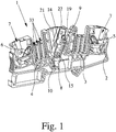
- Fig. 1 shows a terminal block 1 according to the invention in the form of a disconnect terminal, which can be used in particular as a measuring transducer isolating terminal in current transformer measuring circuits of power generation and distribution.
- the terminal block 1 has a generally made of plastic terminal housing 2, in which a two sections 3, 4 existing busbar and two conductor connection elements 5, 6 are arranged.
- the conductor connection elements 5, 6 are formed in the illustrated embodiment as leg spring terminals, in each of which a conductor to be connected can be inserted through a formed in the terminal housing 2 conductor insertion opening 7.
- the conductor connection elements 5, 6 may also be designed as screw terminals, as tension spring terminals or as cutting terminals. With the help of the conductor connection elements 5, 6 can each one electrical conductor to a section 3, 4 of the busbar are connected.
- the conductor connecting elements 5, 6 opposite ends 9, 10 of the sections 3, 4 are bent such that the end 9 of the section 3 is in a plane above the end 10 of the section 4.
- the end 9 of the section 3 is thus bent upward and the end 10 of the section 4 is bent downwards.
- the first position of the separating knife 8 the end 9 of the first portion 3 of the busbar the separating blade 8 at an upper contact portion 11 and the end 10 of the second portion 4, the separating knife 8 contacted at a lower contact portion 12.
- the ends 9, 10 of the two sections 3, 4 of the busbar are each formed as contact forks 13, between which the respective contact region 11, 12 of the separating blade 8 is inserted in the first position, wherein the contact forks 13 and the separating knife 8 dimensioned are that a safe and good electrical contact is guaranteed.
- the contact fork 13 are bent or arranged to the cutting blade 8, that the contact fork 13 impinge almost perpendicular to the two contact region 11, 12 of the cutting blade 8.
- the longitudinal disconnect switch is pivotally mounted in the terminal housing 2 of the disconnect terminal 1.
- the - in Fig. 4 separately shown - longitudinal disconnector has in addition to the separating knife 8 still an insulating housing 14 which is formed so that at least the upper contact portion 11 and the lower contact portion 12 of the separating blade 8 are not surrounded by the insulating housing 14.
- the connection of separating knife 8 and insulating housing 14 is thereby ensured that the separating knife 8 is encapsulated by the insulating housing 14.
- a pivot pin 15 is integrally formed on a side surface of the insulating housing 14, which is mounted in a corresponding opening 18 in a side wall 16 of the terminal housing 2.
- pivot 15 of the circuit breaker or the insulating housing 14 is also guided by the two side walls 16, 17 of the terminal housing.
- the width of the insulating housing 14 is selected so that it fits tightly in the inserted into the terminal housing 2 state on both side walls 16, 17 of the terminal housing 2.
- the pivot axis of the separating knife 8, that is, the pivot pin 15, between the upper contact portion 11 and the lower contact portion 12 is arranged.
- the second position of the separating knife 8 - as in particular from the Fig. 3 and 7 it can be seen - both the end 9 of the first portion 3 of the busbar from the upper contact portion 11 and the end 10 of the second portion 4 of the busbar from the lower contact portion 12 of the separating blade 8 spaced.
- the two separation lines add up between the end 9 of the first part 3 and the upper contact region 11 on the one hand and the end 10 of the second part 4 and the lower contact region 12 on the other hand to a total separation distance, which ensures a secure separation of the two sections 3, 4 of the busbar.
- the cutting blade 8 is still angled so that the below the pivot axis, ie, below the pivot 5, arranged portion of the cutting blade 8 is bent away from the end 10 of the second section 4, as well as from Fig. 3 and 7 is recognizable.
- a total of an operating angle of only about 30 ° sufficient, so that on the one hand, the middle portion of the terminal 1 - and thus the terminal 1 total -small dimensions, on the other hand, the operation of the circuit breaker very easy and comfortable even in confined spaces is possible.
- a locking pin 19, formed by the separating knife 8 and the longitudinal disconnector both in the first position and in the second position in the terminal housing. 2 is latched.
- two recesses 20 are formed in which the latching pin 19 facing side wall 16 of the terminal housing 2, in which the latching pin 19 is positively locked in the first position or in the second position of the cutting blade 8.
- the positive locking of the locking pin 19 in the two recesses 20 leads, together with the narrow guide of the insulating housing 14 between the two side walls 16, 17 of the terminal housing 2 to the fact that for the fitter the locking both in the first position and in the second position clearly noticeable by an acoustic click.
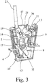
- the assembly of in Fig. 4 separately shown longitudinal circuit breaker in the terminal housing 2 of the terminal 1 can be done simply by the fact that the circuit breaker is inserted into the terminal housing 2 and locked therein.
- a guide groove 21 is formed in the two side walls 16, 17 of the terminal housing 2, in which when inserting the circuit breaker in the terminal housing 2 on the one of the pivot pin 14 and to another on the opposite side surface of the insulating housing 14 trained corresponding guide pin engages.
- This ensures that the circuit breaker can only be plugged into the terminal housing 2 so that the cutting blade 8 is in the locked state of the insulating housing 14 in the terminal housing 2, first in the second, open position.
- the locking of the insulating housing 14 in the terminal housing 2 takes place in that the pivot pin 15 engages in the opening 18 in the side wall 16 of the terminal housing 2, which is visually and acoustically perceptible by a corresponding click.
- an upwardly open actuating shaft 22 is formed, in which a tool, in particular the tip of a screwdriver 23, can be inserted.
- the actuating shaft 22 is dimensioned so that in him the tip of a screwdriver 23 can be inserted, with which also the conductor connection elements 5, 6 can be operated.
- only a simple screwdriver is needed to connect the conductors and to operate the circuit breaker.
- a symbol 26 is printed, which indicates the respective position of the separating blade 8 in the terminal block 1.
- the longitudinal circuit breaker is in the first, closed position, is printed on the visible in this position end face 24 of the insulating housing 14, the symbol 26 of a closed switch.
- the symbol of an open switch is printed on the opposite end face 25.
- the 6 and 7 show an embodiment of a terminal block 1, in which a shift lock 27 for blocking the circuit breaker 8 in the first position ( Fig. 6 ) or in the second position ( Fig. 7 ) is inserted into the terminal housing 2 and locked therein.
- the shift lock 27 is designed so that after locking into the terminal housing 2 only with a tool, for example, with a pair of needle nose pliers from the terminal housing 2 can be removed, so that an accidental operation of the circuit breaker is reliably prevented.
- the same shift lock 27 can be used both in the first position of the circuit breaker as well as in the second position of the circuit breaker in the terminal housing 2, to which the shift lock 27 must be rotated only by 180 °.
- the shift lock 27 on one side of a locking pin 28 which engages depending on the arrangement of the shift lock 27 in an opening 29 in one side wall 16 or the other side wall 17 of the terminal housing 2.
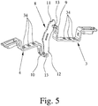
- the operation of the circuit breaker can be done not only by means of a screwdriver 23, but also by means of a switch connection 30, which in the in Fig. 8 illustrated embodiment, two legs 31 and a leg 31 connecting handle portion 32 has.
- a switch connection 30 thus two longitudinal circuit breaker two juxtaposed terminal blocks 1 can be operated simultaneously, for which purpose a leg 31 is inserted into the operating shaft 22 of a longitudinal circuit breaker.
- the terminal blocks 1 shown there have a plurality of guide shafts 33 on both sides of the longitudinal circuit breaker, in which either the contact pins of a test plug, a test socket, a jumper or a jumper can be inserted.
- the contact pins of a test plug, a test socket, a jumper or a jumper can be inserted.
- three openings 34 are formed in the two sections 3, 4 of the busbar ( Fig. 5 ).
Landscapes
- Breakers (AREA)
- Connections Arranged To Contact A Plurality Of Conductors (AREA)
- Distribution Board (AREA)
- Patch Boards (AREA)
Claims (12)
- Bornier, notamment bornier de sectionnement, avec un boîtier à bornes (2), avec un rail conducteur, constitué de deux éléments partiels (3, 4), avec deux éléments de raccordement de conducteurs (5, 6) destinés à raccorder chacun un conducteur sur un élément partiel (3, 4) du rail conducteur et avec une lame de sectionnement (8) logée de manière pivotante dans le boîtier à bornes (2),
les deux éléments partiels (3, 4) étant reliés l'un à l'autre dans une première position de la lame de sectionnement (8) et étant sectionnés l'un de l'autre dans une deuxième position de la lame de sectionnement (8), et
les extrémités (9, 10) des éléments partiels (3, 4) du rail conducteur qui sont opposés aux éléments de raccordement de conducteurs (5, 6) étant recourbées de telle sorte que dans la première position de la lame de sectionnement (8), l'extrémité (9) du premier élément partiel (3) du rail conducteur contacte la lame de sectionnement (8) sur une zone de contact supérieure (11) et l'extrémité (10) du deuxième élément partiel (4) du rail conducteur contacte la lame de sectionnement (8) sur une zone de contact inférieure (12),
caractérisé
en ce que l'axe de pivotement de la lame de sectionnement (8) est placée entre la zone de contact supérieure (11) et la zone de contact inférieure (12),
en ce que dans la deuxième position de la lame de sectionnement (8), aussi bien l'extrémité (9) du premier élément partiel (3) du rail conducteur est écartée de la zone de contact supérieure (11) de la lame de sectionnement (8) qu'également l'extrémité (10) du deuxième élément partiel (4) du rail conducteur est écartée de la zone de contact inférieure (12) de la lame de sectionnement (8) et
en ce que la lame de sectionnement (8) est coudée de telle sorte que la zone de la lame de sectionnement (8) qui est placée en-dessous de l'axe de pivotement soit recourbée en éloignement de l'extrémité (10) du deuxième élément partiel (4) du rail conducteur. - Bornier selon la revendication 1, caractérisé en ce que les extrémités (9, 10) des deux éléments partiels (3, 4) du rail conducteur sont conçues sous la forme de fourches de contact (13).
- Bornier selon la revendication 1 ou 2, caractérisé en ce que la lame de sectionnement (8) est partiellement entourée d'un boîtier isolant (14), au moins la zone de contact supérieure (11) et la zone de contact inférieure (12) n'étant pas entourées par le boîtier isolant (14) et
en ce que sur une surface latérale, le boîtier isolant (14) comporte un pivot (15) et dans une paroi latérale (16) du boîtier à bornes (2) est conçu un orifice (18) correspondant. - Bornier selon la revendication 3, caractérisé en ce que la lame de sectionnement (8) est enclenchable aussi bien dans la première position que dans la deuxième position, pour ce faire, le boîtier isolant (14) comporte un tenon d'enclenchement (19) sur une surface latérale, et dans une paroi latérale (16) du boîtier à bornes (2) sont conçus deux évidements (20) correspondants dans lesquels le tenon d'enclenchement (19) s'enclenche dans la première position et dans la deuxième position de la lame de sectionnement (8).
- Bornier selon la revendication 4, caractérisé en ce que le boîtier isolant (14) de la lame de sectionnement (8) est dimensionné de telle sorte que lors du pivotement de la première position dans la deuxième position, le boîtier isolant (14) soit guidé par les parois latérales (16, 17) du boîtier à bornes (2).
- Bornier selon la revendication 5, caractérisé en ce que la lame de sectionnement (8) est insérable et enclenchable par le boîtier isolant (14) dans le boîtier à bornes (2), de préférence une ou les deux parois latérales (16, 17) du boîtier à bornes (2) comportant une rainure de guidage (21), la rainure de guidage (21), respectivement les rainures de guidage (21) étant placées de telle sorte qu'après l'insertion, la lame de sectionnement (8) soit placée dans la deuxième position.
- Bornier selon l'une quelconque des revendications 3 à 6, caractérisé en ce que le boîtier isolant (14) comporte un trou de manoeuvre (22) ouvert sur le dessus, dans lequel est insérable un outil, notamment la pointe d'un tournevis (23), le trou de manoeuvre (22) s'écoulant de préférence avec un déport latéral par rapport à la zone de la lame de sectionnement (8) placée au-dessus de l'axe de pivotement.
- Bornier selon l'une quelconque des revendications 3 à 7, caractérisé en ce que sur les deux faces frontales (24, 25) du boîtier isolant (14), un symbole (26) pour la position respective de la lame de sectionnement (8) est appliqué de telle sorte que le symbole (26) soit identifiable lors en jetant un coup d'oeil à la face supérieure du boîtier à bornes (2).
- Bornier selon l'une quelconque des revendications 1 à 8, caractérisé en ce qu'un blocage de commutation (27) destiné à bloquer la lame de sectionnement (8) dans la première et/ou dans la deuxième position est insérable dans le boîtier à bornes (2), le blocage de commutation (27) étant de préférence enclenchable dans le boîtier à bornes (2) de telle sorte que le blocage de commutation (27) ne puisse être à nouveau retiré du boîtier à bornes (2) qu'à l'aide d'un outil.
- Bornier selon les revendications 8 et 9, caractérisé en ce que la face frontale qui lorsque le blocage de commutation (27) est inséré fait face au boîtier isolant (14) est ouverte ou transparente, de sorte que même lorsque le blocage de commutation (27) est inséré, le symbole (26) sur le boîtier isolant (14) soit identifiable par le dessus.
- Bornier selon l'une quelconque des revendications 7 à 10, caractérisé en ce qu'une liaison de commutation (30) qui comporte au moins deux branches (31) et une partie de préhension (32) reliant les branches (31) est insérable par une branche (31) dans le trou de manoeuvre (22) dans le boîtier isolant (14).
- Bornier selon l'une quelconque des revendications 1 à 11, caractérisé en ce que le boîtier à bornes (2) comporte plusieurs gorges de guidage (33) et dans les deux éléments partiels (3, 4) du rail conducteur sont conçus plusieurs orifices (34) destinés à introduire une tige de contact d'une fiche de test, d'une prise pour fiche de test, d'un pontet ou d'un pont de commutation.
Applications Claiming Priority (2)
| Application Number | Priority Date | Filing Date | Title |
|---|---|---|---|
| DE102008014176A DE102008014176B4 (de) | 2008-03-14 | 2008-03-14 | Reihenklemme, insbesondere Trennklemme, und Längstrennschalter |
| PCT/EP2009/001792 WO2009112264A1 (fr) | 2008-03-14 | 2009-03-12 | Borne serre-fil, en particulier borne sectionnable |
Publications (2)
| Publication Number | Publication Date |
|---|---|
| EP2255369A1 EP2255369A1 (fr) | 2010-12-01 |
| EP2255369B1 true EP2255369B1 (fr) | 2018-11-14 |
Family
ID=40796328
Family Applications (1)
| Application Number | Title | Priority Date | Filing Date |
|---|---|---|---|
| EP09720012.5A Active EP2255369B1 (fr) | 2008-03-14 | 2009-03-12 | Borne serre-fil, en particulier borne sectionnable |
Country Status (7)
| Country | Link |
|---|---|
| US (1) | US8581131B2 (fr) |
| EP (1) | EP2255369B1 (fr) |
| JP (1) | JP5542698B2 (fr) |
| CN (1) | CN102027559B (fr) |
| DE (1) | DE102008014176B4 (fr) |
| ES (1) | ES2703758T3 (fr) |
| WO (1) | WO2009112264A1 (fr) |
Families Citing this family (23)
| Publication number | Priority date | Publication date | Assignee | Title |
|---|---|---|---|---|
| DE102008014177A1 (de) * | 2008-03-14 | 2009-09-17 | Phoenix Contact Gmbh & Co. Kg | Reihenklemme und Reihenklemmblock |
| DE102010033808B4 (de) * | 2010-08-09 | 2016-12-22 | Phoenix Contact Gmbh & Co. Kg | Reihenklemme |
| DE102010052871B4 (de) * | 2010-12-01 | 2014-06-05 | Phoenix Contact Gmbh & Co. Kg | Reihenklemme |
| DE102011105157B4 (de) * | 2011-06-17 | 2019-01-03 | Phoenix Contact Gmbh & Co. Kg | Elektrisches Verbindungsmodul mit unterbrechbarem Stromkreis und Verfahren zum Erfassen einer Stromstärke |
| DE102012010244A1 (de) * | 2012-05-24 | 2013-11-28 | Phoenix Contact Gmbh & Co. Kg | Elektrische Anschlussklemme |
| USD700897S1 (en) * | 2012-07-31 | 2014-03-11 | Phoenix Contact Gmbh & Co. Kg | Socket module for an electronic relay |
| DE102012107264A1 (de) * | 2012-08-08 | 2014-02-13 | Phoenix Contact Gmbh & Co. Kg | Anschlussmodul |
| DE102014102602A1 (de) | 2014-02-27 | 2015-08-27 | Phoenix Contact Gmbh & Co. Kg | Reihenklemme und Reihenklemmenblock |
| DE102015103113A1 (de) * | 2015-03-04 | 2016-09-08 | Phoenix Contact Gmbh & Co. Kg | Trennklemme |
| US9396889B1 (en) * | 2015-04-03 | 2016-07-19 | Eaton Corporation | Electrical switching apparatus and secondary disconnect assembly with cradle assembly alignment and positioning features therefor |
| DE102015121057A1 (de) | 2015-12-03 | 2017-06-08 | Phoenix Contact Gmbh & Co. Kg | Elektrische Klemme |
| DE202016101051U1 (de) * | 2016-02-29 | 2017-05-30 | Wago Verwaltungsgesellschaft Mbh | Reihenklemme |
| DE102016004884B4 (de) * | 2016-04-22 | 2020-06-04 | Sew-Eurodrive Gmbh & Co Kg | Antriebssystem mit einer Zwischenkreisverschienung |
| TWI619317B (zh) * | 2016-06-20 | 2018-03-21 | Improved structure of the connector head limiter of the wire connection terminal | |
| JP6733368B2 (ja) * | 2016-06-29 | 2020-07-29 | オムロン株式会社 | 端子接続機構およびスイッチ |
| USD901400S1 (en) * | 2017-03-07 | 2020-11-10 | Phoenix Contact Gmbh & Co. Kg | Electrical connector |
| JP1623420S (fr) * | 2018-03-14 | 2019-02-04 | ||
| JP1623945S (fr) * | 2018-03-14 | 2019-02-04 | ||
| DE102018133438A1 (de) * | 2018-12-21 | 2020-06-25 | Weidmüller Interface GmbH & Co. KG | Trennklemme |
| DE102019112243B4 (de) | 2019-05-10 | 2022-10-06 | Phoenix Contact Gmbh & Co. Kg | Prüfadapter mit Schaltsperre und die dazugehörige Prüfanordnung |
| DE102019123285A1 (de) | 2019-08-30 | 2021-03-04 | Weidmüller Interface GmbH & Co. KG | Anordnung von Trennklemmen mit Kopplungseinrichtung, Trennklemme mit Kopplungseinrichtung, und Trennklemme mit Schaltzustandsanzeige |
| DE102020106323A1 (de) | 2020-03-09 | 2021-09-09 | Weidmüller Interface GmbH & Co. KG | Anordnung von Trennklemmen mit Steckeinheit und Verfahren zum Kurzschließen einer solchen Anordnung |
| CN113192789B (zh) * | 2021-03-24 | 2023-05-12 | 天津平高智能电气有限公司 | 一种柱上隔离开关及其接线端子 |
Citations (1)
| Publication number | Priority date | Publication date | Assignee | Title |
|---|---|---|---|---|
| DE4444551A1 (de) * | 1994-12-01 | 1996-06-05 | Wago Verwaltungs Gmbh | Stromwandler-Trennklemme |
Family Cites Families (19)
| Publication number | Priority date | Publication date | Assignee | Title |
|---|---|---|---|---|
| US2620415A (en) * | 1949-05-04 | 1952-12-02 | Ohio Brass Co | Knife blade switch |
| DE1490497B2 (de) * | 1963-12-14 | 1971-02-11 | Siemens AG 1000 Berlin u 8000 München | Reihenklemme als Trennklemme |
| US3676629A (en) * | 1971-04-05 | 1972-07-11 | S & C Electric Co | Switch construction with non-bounce contacts |
| US3840717A (en) * | 1973-08-20 | 1974-10-08 | Gen Electric | Manually operated rotary switch and combination load contact-fuse clip therefor |
| JPS55154028A (en) * | 1979-05-21 | 1980-12-01 | Hitachi Ltd | Circuit breaker |
| JPS57143547U (fr) * | 1981-03-02 | 1982-09-09 | ||
| DE58905551D1 (de) * | 1989-03-04 | 1993-10-14 | Weidmueller Interface | Doppeltrennklemme. |
| DE4106555A1 (de) * | 1990-03-02 | 1991-09-05 | Phoenix Elekt | Elektrische anschlussklemme |
| JPH05336621A (ja) * | 1992-05-28 | 1993-12-17 | Fuji Electric Co Ltd | 回路しゃ断器の取付け構造 |
| DE9315474U1 (de) * | 1993-10-09 | 1994-01-13 | Wago Verwaltungsgesellschaft Mbh, 32423 Minden | Elektrische Klemme mit einem Sammelschienenanschluß |
| JP3228002B2 (ja) * | 1994-06-08 | 2001-11-12 | 株式会社日立製作所 | 回路遮断器 |
| DE4444556A1 (de) * | 1994-12-01 | 1996-06-05 | Wago Verwaltungs Gmbh | Schaltbare Reihenklemme |
| US5669788A (en) * | 1996-09-18 | 1997-09-23 | Allen-Bradley Company, Inc. | Screwless terminal block linking apparatus |
| JP3997818B2 (ja) * | 2001-05-28 | 2007-10-24 | 富士電機機器制御株式会社 | 配線用回路しゃ断器 |
| CN2708478Y (zh) * | 2004-04-01 | 2005-07-06 | 王世孝 | 大容量隔离开关 |
| US7005594B2 (en) * | 2004-04-16 | 2006-02-28 | Ls Industrial Systems Co., Ltd. | Movable contactor assembly of circuit breaker |
| US7189935B1 (en) * | 2005-12-08 | 2007-03-13 | General Electric Company | Contact arm apparatus and method of assembly thereof |
| DE102008014177A1 (de) * | 2008-03-14 | 2009-09-17 | Phoenix Contact Gmbh & Co. Kg | Reihenklemme und Reihenklemmblock |
| DE102008014179B4 (de) * | 2008-03-14 | 2012-08-02 | Phoenix Contact Gmbh & Co. Kg | Schaltbrücke und Baueinheit aus mindestens zwei elektrischen Reihenklemmen und einer Schaltbrücke |
-
2008
- 2008-03-14 DE DE102008014176A patent/DE102008014176B4/de not_active Expired - Fee Related
-
2009
- 2009-03-12 WO PCT/EP2009/001792 patent/WO2009112264A1/fr active Application Filing
- 2009-03-12 CN CN200980117097.1A patent/CN102027559B/zh active Active
- 2009-03-12 ES ES09720012T patent/ES2703758T3/es active Active
- 2009-03-12 JP JP2010550089A patent/JP5542698B2/ja not_active Expired - Fee Related
- 2009-03-12 EP EP09720012.5A patent/EP2255369B1/fr active Active
- 2009-03-12 US US12/922,633 patent/US8581131B2/en active Active
Patent Citations (1)
| Publication number | Priority date | Publication date | Assignee | Title |
|---|---|---|---|---|
| DE4444551A1 (de) * | 1994-12-01 | 1996-06-05 | Wago Verwaltungs Gmbh | Stromwandler-Trennklemme |
Also Published As
| Publication number | Publication date |
|---|---|
| ES2703758T3 (es) | 2019-03-12 |
| WO2009112264A1 (fr) | 2009-09-17 |
| DE102008014176A1 (de) | 2009-09-17 |
| EP2255369A1 (fr) | 2010-12-01 |
| JP5542698B2 (ja) | 2014-07-09 |
| CN102027559B (zh) | 2014-08-20 |
| US8581131B2 (en) | 2013-11-12 |
| CN102027559A (zh) | 2011-04-20 |
| DE102008014176B4 (de) | 2011-01-27 |
| US20110062011A1 (en) | 2011-03-17 |
| JP2011517500A (ja) | 2011-06-09 |
Similar Documents
| Publication | Publication Date | Title |
|---|---|---|
| EP2255369B1 (fr) | Borne serre-fil, en particulier borne sectionnable | |
| EP2255409B1 (fr) | Pont de commutation et unité composée d'au moins deux blocs de jonction électriques et d'un pont de commutation | |
| EP2255410B1 (fr) | Barrette a bornes ou bloc de barrettes a bornes | |
| EP1753087B1 (fr) | Borne électrique | |
| EP1251590B1 (fr) | Borne électrique | |
| EP2839544B1 (fr) | Bornier de test | |
| DE102008057754B4 (de) | Baueinheit aus mindestens zwei nebeneinander angeordneten Trennklemmen und mindestens zwei miteinander verbundenen Anschlusssteckern | |
| EP2965389B1 (fr) | Bloc de fixation | |
| EP3176879B1 (fr) | Borne électrique | |
| EP1811604A2 (fr) | Barette à bornes électriques | |
| EP1529302A1 (fr) | Commutateur electrique | |
| DE102015102257B4 (de) | Elektrische Reihenklemme und Steckersystem für Reihenklemmen mit einem Betriebs- oder Prüfstecker | |
| EP0984513B1 (fr) | Pièce d'insertion pour un connecteur industriel | |
| EP2819246B1 (fr) | Dispositif de raccordement, notamment appareil de commutation, équipé d'une borne à ressort et d'un entraînement destiné à l'actionnement de la borne à ressort | |
| EP1523065B1 (fr) | Borne électrique | |
| DE102008014180B4 (de) | Trennklemme, insbesondere Neutralleiter-Trennklemme | |
| EP3590153B1 (fr) | Agencement de barettes à borne | |
| WO2019076537A1 (fr) | Pince de fixation | |
| DE102006008971B4 (de) | Funktionsstecker und Baueinheit aus zwei elektrischen Reihenklemmen und einem Funktionsstecker | |
| DE20312123U1 (de) | Elektrische Klemme | |
| WO2009030719A1 (fr) | Commutateur comprenant au moins deux niveaux de commutation | |
| DE102008011217B4 (de) | Betätigungswerkzeug zum Anschließen eines isolierten Leiters | |
| EP3281215A1 (fr) | Système convertisseur de courant et sectionneur équipé d'un tel système |
Legal Events
| Date | Code | Title | Description |
|---|---|---|---|
| PUAI | Public reference made under article 153(3) epc to a published international application that has entered the european phase |
Free format text: ORIGINAL CODE: 0009012 |
|
| 17P | Request for examination filed |
Effective date: 20101014 |
|
| AK | Designated contracting states |
Kind code of ref document: A1 Designated state(s): AT BE BG CH CY CZ DE DK EE ES FI FR GB GR HR HU IE IS IT LI LT LU LV MC MK MT NL NO PL PT RO SE SI SK TR |
|
| AX | Request for extension of the european patent |
Extension state: AL BA RS |
|
| DAX | Request for extension of the european patent (deleted) | ||
| 17Q | First examination report despatched |
Effective date: 20140520 |
|
| GRAP | Despatch of communication of intention to grant a patent |
Free format text: ORIGINAL CODE: EPIDOSNIGR1 |
|
| STAA | Information on the status of an ep patent application or granted ep patent |
Free format text: STATUS: GRANT OF PATENT IS INTENDED |
|
| INTG | Intention to grant announced |
Effective date: 20180522 |
|
| GRAS | Grant fee paid |
Free format text: ORIGINAL CODE: EPIDOSNIGR3 |
|
| GRAA | (expected) grant |
Free format text: ORIGINAL CODE: 0009210 |
|
| STAA | Information on the status of an ep patent application or granted ep patent |
Free format text: STATUS: THE PATENT HAS BEEN GRANTED |
|
| AK | Designated contracting states |
Kind code of ref document: B1 Designated state(s): AT BE BG CH CY CZ DE DK EE ES FI FR GB GR HR HU IE IS IT LI LT LU LV MC MK MT NL NO PL PT RO SE SI SK TR |
|
| REG | Reference to a national code |
Ref country code: GB Ref legal event code: FG4D Free format text: NOT ENGLISH |
|
| REG | Reference to a national code |
Ref country code: CH Ref legal event code: EP Ref country code: AT Ref legal event code: REF Ref document number: 1065838 Country of ref document: AT Kind code of ref document: T Effective date: 20181115 |
|
| REG | Reference to a national code |
Ref country code: DE Ref legal event code: R096 Ref document number: 502009015454 Country of ref document: DE |
|
| REG | Reference to a national code |
Ref country code: IE Ref legal event code: FG4D Free format text: LANGUAGE OF EP DOCUMENT: GERMAN |
|
| REG | Reference to a national code |
Ref country code: ES Ref legal event code: FG2A Ref document number: 2703758 Country of ref document: ES Kind code of ref document: T3 Effective date: 20190312 |
|
| REG | Reference to a national code |
Ref country code: NL Ref legal event code: MP Effective date: 20181114 |
|
| REG | Reference to a national code |
Ref country code: LT Ref legal event code: MG4D |
|
| PG25 | Lapsed in a contracting state [announced via postgrant information from national office to epo] |
Ref country code: LV Free format text: LAPSE BECAUSE OF FAILURE TO SUBMIT A TRANSLATION OF THE DESCRIPTION OR TO PAY THE FEE WITHIN THE PRESCRIBED TIME-LIMIT Effective date: 20181114 Ref country code: HR Free format text: LAPSE BECAUSE OF FAILURE TO SUBMIT A TRANSLATION OF THE DESCRIPTION OR TO PAY THE FEE WITHIN THE PRESCRIBED TIME-LIMIT Effective date: 20181114 Ref country code: BG Free format text: LAPSE BECAUSE OF FAILURE TO SUBMIT A TRANSLATION OF THE DESCRIPTION OR TO PAY THE FEE WITHIN THE PRESCRIBED TIME-LIMIT Effective date: 20190214 Ref country code: NO Free format text: LAPSE BECAUSE OF FAILURE TO SUBMIT A TRANSLATION OF THE DESCRIPTION OR TO PAY THE FEE WITHIN THE PRESCRIBED TIME-LIMIT Effective date: 20190214 Ref country code: LT Free format text: LAPSE BECAUSE OF FAILURE TO SUBMIT A TRANSLATION OF THE DESCRIPTION OR TO PAY THE FEE WITHIN THE PRESCRIBED TIME-LIMIT Effective date: 20181114 Ref country code: IS Free format text: LAPSE BECAUSE OF FAILURE TO SUBMIT A TRANSLATION OF THE DESCRIPTION OR TO PAY THE FEE WITHIN THE PRESCRIBED TIME-LIMIT Effective date: 20190314 Ref country code: FI Free format text: LAPSE BECAUSE OF FAILURE TO SUBMIT A TRANSLATION OF THE DESCRIPTION OR TO PAY THE FEE WITHIN THE PRESCRIBED TIME-LIMIT Effective date: 20181114 |
|
| PG25 | Lapsed in a contracting state [announced via postgrant information from national office to epo] |
Ref country code: GR Free format text: LAPSE BECAUSE OF FAILURE TO SUBMIT A TRANSLATION OF THE DESCRIPTION OR TO PAY THE FEE WITHIN THE PRESCRIBED TIME-LIMIT Effective date: 20190215 Ref country code: SE Free format text: LAPSE BECAUSE OF FAILURE TO SUBMIT A TRANSLATION OF THE DESCRIPTION OR TO PAY THE FEE WITHIN THE PRESCRIBED TIME-LIMIT Effective date: 20181114 Ref country code: PT Free format text: LAPSE BECAUSE OF FAILURE TO SUBMIT A TRANSLATION OF THE DESCRIPTION OR TO PAY THE FEE WITHIN THE PRESCRIBED TIME-LIMIT Effective date: 20190314 Ref country code: NL Free format text: LAPSE BECAUSE OF FAILURE TO SUBMIT A TRANSLATION OF THE DESCRIPTION OR TO PAY THE FEE WITHIN THE PRESCRIBED TIME-LIMIT Effective date: 20181114 |
|
| PG25 | Lapsed in a contracting state [announced via postgrant information from national office to epo] |
Ref country code: DK Free format text: LAPSE BECAUSE OF FAILURE TO SUBMIT A TRANSLATION OF THE DESCRIPTION OR TO PAY THE FEE WITHIN THE PRESCRIBED TIME-LIMIT Effective date: 20181114 Ref country code: PL Free format text: LAPSE BECAUSE OF FAILURE TO SUBMIT A TRANSLATION OF THE DESCRIPTION OR TO PAY THE FEE WITHIN THE PRESCRIBED TIME-LIMIT Effective date: 20181114 Ref country code: CZ Free format text: LAPSE BECAUSE OF FAILURE TO SUBMIT A TRANSLATION OF THE DESCRIPTION OR TO PAY THE FEE WITHIN THE PRESCRIBED TIME-LIMIT Effective date: 20181114 |
|
| REG | Reference to a national code |
Ref country code: DE Ref legal event code: R097 Ref document number: 502009015454 Country of ref document: DE |
|
| PG25 | Lapsed in a contracting state [announced via postgrant information from national office to epo] |
Ref country code: RO Free format text: LAPSE BECAUSE OF FAILURE TO SUBMIT A TRANSLATION OF THE DESCRIPTION OR TO PAY THE FEE WITHIN THE PRESCRIBED TIME-LIMIT Effective date: 20181114 Ref country code: SK Free format text: LAPSE BECAUSE OF FAILURE TO SUBMIT A TRANSLATION OF THE DESCRIPTION OR TO PAY THE FEE WITHIN THE PRESCRIBED TIME-LIMIT Effective date: 20181114 Ref country code: EE Free format text: LAPSE BECAUSE OF FAILURE TO SUBMIT A TRANSLATION OF THE DESCRIPTION OR TO PAY THE FEE WITHIN THE PRESCRIBED TIME-LIMIT Effective date: 20181114 |
|
| PLBE | No opposition filed within time limit |
Free format text: ORIGINAL CODE: 0009261 |
|
| STAA | Information on the status of an ep patent application or granted ep patent |
Free format text: STATUS: NO OPPOSITION FILED WITHIN TIME LIMIT |
|
| 26N | No opposition filed |
Effective date: 20190815 |
|
| PG25 | Lapsed in a contracting state [announced via postgrant information from national office to epo] |
Ref country code: SI Free format text: LAPSE BECAUSE OF FAILURE TO SUBMIT A TRANSLATION OF THE DESCRIPTION OR TO PAY THE FEE WITHIN THE PRESCRIBED TIME-LIMIT Effective date: 20181114 Ref country code: MC Free format text: LAPSE BECAUSE OF FAILURE TO SUBMIT A TRANSLATION OF THE DESCRIPTION OR TO PAY THE FEE WITHIN THE PRESCRIBED TIME-LIMIT Effective date: 20181114 |
|
| REG | Reference to a national code |
Ref country code: CH Ref legal event code: PL |
|
| PG25 | Lapsed in a contracting state [announced via postgrant information from national office to epo] |
Ref country code: LU Free format text: LAPSE BECAUSE OF NON-PAYMENT OF DUE FEES Effective date: 20190312 |
|
| REG | Reference to a national code |
Ref country code: BE Ref legal event code: MM Effective date: 20190331 |
|
| PG25 | Lapsed in a contracting state [announced via postgrant information from national office to epo] |
Ref country code: CH Free format text: LAPSE BECAUSE OF NON-PAYMENT OF DUE FEES Effective date: 20190331 Ref country code: LI Free format text: LAPSE BECAUSE OF NON-PAYMENT OF DUE FEES Effective date: 20190331 Ref country code: IE Free format text: LAPSE BECAUSE OF NON-PAYMENT OF DUE FEES Effective date: 20190312 |
|
| PG25 | Lapsed in a contracting state [announced via postgrant information from national office to epo] |
Ref country code: BE Free format text: LAPSE BECAUSE OF NON-PAYMENT OF DUE FEES Effective date: 20190331 |
|
| PG25 | Lapsed in a contracting state [announced via postgrant information from national office to epo] |
Ref country code: TR Free format text: LAPSE BECAUSE OF FAILURE TO SUBMIT A TRANSLATION OF THE DESCRIPTION OR TO PAY THE FEE WITHIN THE PRESCRIBED TIME-LIMIT Effective date: 20181114 |
|
| PGFP | Annual fee paid to national office [announced via postgrant information from national office to epo] |
Ref country code: GB Payment date: 20200327 Year of fee payment: 12 |
|
| PG25 | Lapsed in a contracting state [announced via postgrant information from national office to epo] |
Ref country code: MT Free format text: LAPSE BECAUSE OF FAILURE TO SUBMIT A TRANSLATION OF THE DESCRIPTION OR TO PAY THE FEE WITHIN THE PRESCRIBED TIME-LIMIT Effective date: 20181114 |
|
| REG | Reference to a national code |
Ref country code: AT Ref legal event code: MM01 Ref document number: 1065838 Country of ref document: AT Kind code of ref document: T Effective date: 20190312 |
|
| PG25 | Lapsed in a contracting state [announced via postgrant information from national office to epo] |
Ref country code: AT Free format text: LAPSE BECAUSE OF NON-PAYMENT OF DUE FEES Effective date: 20190312 |
|
| PGFP | Annual fee paid to national office [announced via postgrant information from national office to epo] |
Ref country code: IT Payment date: 20210323 Year of fee payment: 13 Ref country code: FR Payment date: 20210326 Year of fee payment: 13 |
|
| PG25 | Lapsed in a contracting state [announced via postgrant information from national office to epo] |
Ref country code: CY Free format text: LAPSE BECAUSE OF FAILURE TO SUBMIT A TRANSLATION OF THE DESCRIPTION OR TO PAY THE FEE WITHIN THE PRESCRIBED TIME-LIMIT Effective date: 20181114 |
|
| PG25 | Lapsed in a contracting state [announced via postgrant information from national office to epo] |
Ref country code: HU Free format text: LAPSE BECAUSE OF FAILURE TO SUBMIT A TRANSLATION OF THE DESCRIPTION OR TO PAY THE FEE WITHIN THE PRESCRIBED TIME-LIMIT; INVALID AB INITIO Effective date: 20090312 |
|
| GBPC | Gb: european patent ceased through non-payment of renewal fee |
Effective date: 20210312 |
|
| PG25 | Lapsed in a contracting state [announced via postgrant information from national office to epo] |
Ref country code: GB Free format text: LAPSE BECAUSE OF NON-PAYMENT OF DUE FEES Effective date: 20210312 |
|
| PG25 | Lapsed in a contracting state [announced via postgrant information from national office to epo] |
Ref country code: MK Free format text: LAPSE BECAUSE OF FAILURE TO SUBMIT A TRANSLATION OF THE DESCRIPTION OR TO PAY THE FEE WITHIN THE PRESCRIBED TIME-LIMIT Effective date: 20181114 |
|
| PG25 | Lapsed in a contracting state [announced via postgrant information from national office to epo] |
Ref country code: FR Free format text: LAPSE BECAUSE OF NON-PAYMENT OF DUE FEES Effective date: 20220331 |
|
| PG25 | Lapsed in a contracting state [announced via postgrant information from national office to epo] |
Ref country code: IT Free format text: LAPSE BECAUSE OF NON-PAYMENT OF DUE FEES Effective date: 20220312 |
|
| P01 | Opt-out of the competence of the unified patent court (upc) registered |
Effective date: 20230424 |
|
| REG | Reference to a national code |
Ref country code: DE Ref legal event code: R084 Ref document number: 502009015454 Country of ref document: DE |
|
| PGFP | Annual fee paid to national office [announced via postgrant information from national office to epo] |
Ref country code: DE Payment date: 20240529 Year of fee payment: 16 |
|
| PGFP | Annual fee paid to national office [announced via postgrant information from national office to epo] |
Ref country code: ES Payment date: 20240412 Year of fee payment: 16 |