EP2255369B1 - Modular terminal, particularly disconnect terminal - Google Patents
Modular terminal, particularly disconnect terminal Download PDFInfo
- Publication number
- EP2255369B1 EP2255369B1 EP09720012.5A EP09720012A EP2255369B1 EP 2255369 B1 EP2255369 B1 EP 2255369B1 EP 09720012 A EP09720012 A EP 09720012A EP 2255369 B1 EP2255369 B1 EP 2255369B1
- Authority
- EP
- European Patent Office
- Prior art keywords
- terminal
- housing
- busbar
- isolating blade
- insulating housing
- Prior art date
- Legal status (The legal status is an assumption and is not a legal conclusion. Google has not performed a legal analysis and makes no representation as to the accuracy of the status listed.)
- Active
Links
- 239000004020 conductor Substances 0.000 claims description 23
- 238000012360 testing method Methods 0.000 claims description 5
- 238000003780 insertion Methods 0.000 claims description 3
- 230000037431 insertion Effects 0.000 claims description 3
- 230000000903 blocking effect Effects 0.000 claims description 2
- 238000000926 separation method Methods 0.000 description 18
- 230000015572 biosynthetic process Effects 0.000 description 4
- 238000010248 power generation Methods 0.000 description 2
- 238000006073 displacement reaction Methods 0.000 description 1
- 238000009434 installation Methods 0.000 description 1
- 230000001681 protective effect Effects 0.000 description 1
Images


Classifications
-
- H—ELECTRICITY
- H01—ELECTRIC ELEMENTS
- H01H—ELECTRIC SWITCHES; RELAYS; SELECTORS; EMERGENCY PROTECTIVE DEVICES
- H01H21/00—Switches operated by an operating part in the form of a pivotable member acted upon directly by a solid body, e.g. by a hand
- H01H21/54—Lever switches with blade-type contact co-operating with one or two spring-clip contacts, e.g. knife switch
-
- H—ELECTRICITY
- H01—ELECTRIC ELEMENTS
- H01H—ELECTRIC SWITCHES; RELAYS; SELECTORS; EMERGENCY PROTECTIVE DEVICES
- H01H1/00—Contacts
- H01H1/12—Contacts characterised by the manner in which co-operating contacts engage
- H01H1/36—Contacts characterised by the manner in which co-operating contacts engage by sliding
- H01H1/365—Bridging contacts
-
- H—ELECTRICITY
- H01—ELECTRIC ELEMENTS
- H01R—ELECTRICALLY-CONDUCTIVE CONNECTIONS; STRUCTURAL ASSOCIATIONS OF A PLURALITY OF MUTUALLY-INSULATED ELECTRICAL CONNECTING ELEMENTS; COUPLING DEVICES; CURRENT COLLECTORS
- H01R9/00—Structural associations of a plurality of mutually-insulated electrical connecting elements, e.g. terminal strips or terminal blocks; Terminals or binding posts mounted upon a base or in a case; Bases therefor
- H01R9/22—Bases, e.g. strip, block, panel
- H01R9/24—Terminal blocks
- H01R9/26—Clip-on terminal blocks for side-by-side rail- or strip-mounting
- H01R9/2625—Clip-on terminal blocks for side-by-side rail- or strip-mounting with built-in electrical component
- H01R9/2633—Clip-on terminal blocks for side-by-side rail- or strip-mounting with built-in electrical component with built-in switch
-
- H—ELECTRICITY
- H01—ELECTRIC ELEMENTS
- H01H—ELECTRIC SWITCHES; RELAYS; SELECTORS; EMERGENCY PROTECTIVE DEVICES
- H01H1/00—Contacts
- H01H1/12—Contacts characterised by the manner in which co-operating contacts engage
- H01H1/36—Contacts characterised by the manner in which co-operating contacts engage by sliding
- H01H1/42—Knife-and-clip contacts
-
- H—ELECTRICITY
- H01—ELECTRIC ELEMENTS
- H01R—ELECTRICALLY-CONDUCTIVE CONNECTIONS; STRUCTURAL ASSOCIATIONS OF A PLURALITY OF MUTUALLY-INSULATED ELECTRICAL CONNECTING ELEMENTS; COUPLING DEVICES; CURRENT COLLECTORS
- H01R4/00—Electrically-conductive connections between two or more conductive members in direct contact, i.e. touching one another; Means for effecting or maintaining such contact; Electrically-conductive connections having two or more spaced connecting locations for conductors and using contact members penetrating insulation
- H01R4/28—Clamped connections, spring connections
- H01R4/48—Clamped connections, spring connections utilising a spring, clip, or other resilient member
- H01R4/4809—Clamped connections, spring connections utilising a spring, clip, or other resilient member using a leaf spring to bias the conductor toward the busbar
- H01R4/48185—Clamped connections, spring connections utilising a spring, clip, or other resilient member using a leaf spring to bias the conductor toward the busbar adapted for axial insertion of a wire end
- H01R4/48275—Clamped connections, spring connections utilising a spring, clip, or other resilient member using a leaf spring to bias the conductor toward the busbar adapted for axial insertion of a wire end with an opening in the housing for insertion of a release tool
Definitions
- the invention relates to a terminal block, in particular a disconnect terminal, with a terminal housing, with a two-piece busbar, with two conductor connection elements for connecting one conductor to a portion of the busbar and with a pivotally mounted in the terminal housing separating knife, wherein the two sections are connected to each other in a first position of the separating blade and separated from each other in a second position of the separating blade, and wherein the conductor connection elements remote from the ends of the sections of the busbar are bent such that in the first position of the separating blade, the end of the first section of the busbar, the cutting blade at an upper contact portion and the end of the second portion of the bus bar contacts the disconnecting blade at a lower contact area.
- the invention also relates to a circuit breaker with a disconnecting blade for pivotal arrangement in a terminal housing a terminal.
- Electrical terminal blocks have been known for decades and are used millions of times in the wiring of electrical systems and equipment.
- the terminals are usually snapped onto mounting rails, which in turn are often arranged in a plurality in a control cabinet.
- conductor connection elements predominantly screw terminals or tension spring terminals are used in terminal blocks.
- cutting terminals or leg spring terminals can be used.
- the basic type of terminal block is the connection terminal, which has at least two conductor connection elements, which are electrically connected to one another via an electrically conductive connection rail, the busbar.
- this basic type which is often referred to as a feed-through terminal
- protective conductor terminals, knife disconnect terminals and installation terminals may be mentioned here.
- terminal blocks which are used in power converter measuring circuits of power generation and distribution, are often different Switching, separating and testing tasks to realize. According to their use, such terminal blocks are often referred to as transducer disconnect terminals. With the help of a arranged in the terminal housing of the disconnect terminal circuit breaker while the two sections of the busbar can either be connected to each other or separated.
- An electrical terminal block in which two parts of a busbar can be separated via a separation point is from the DE 41 06 555 A1 known.
- a double-level terminal which has two busbars running one above the other in the terminal housing, wherein both busbars can be separated by a separation point accessible from the top of the terminal block.
- the separation point is designed as a knife-separating point, which has a pivotally mounted in the housing separating knife.
- a current transformer disconnect terminal in which the separation point is formed by a rotatably arranged in the terminal housing contact disc.
- the separation point By forming the separation point as a contact disk, it is possible either to connect the two sections of the busbar with each other or to separate from each other. If the two sections of the busbar are separated from each other, then the converter-side section of the busbar is electrically conductively connected via the contact disk to an additionally arranged in the terminal housing contact piece, in which contact piece, a shorting bridge can be inserted. Due to the formation of the separation point as a contact disk, this separation clamp has relatively large dimensions. In addition, the operating angle for securely pivoting the contact disc from the first position to the second position is relatively large.
- a knife switch for the electrical connection of conductors connected to two terminals.
- the two terminals are connected by a separating knife, the separating knife consists of two straight rails.
- the cutting knife is rotatably mounted around a rod with the axis of rotation in the rod. The rotation
- the separating knife is made by a lever that can be connected to the separating knife.
- a disconnect terminal described above in which the separation point is formed by a pivotally mounted in the terminal housing separating blade.
- the cutting knife is mounted with its lower end in a receptacle in the terminal housing, so that the cutting blade can be pivoted about this bearing point. While the separating knife contacted in the first position of both sections of the busbar is, contacted the cutting blade in the second position, only one of the two sections, so that the busbar is disconnected. To ensure a sufficiently large separation distance between the separating knife and the end of the second connecting piece facing away from the conductor connecting element, a relatively large operating angle is also required in the case of this separating clamp.
- the present invention is therefore an object of the invention to provide a terminal described above, in which the switching of the circuit breaker space-saving as possible but still user-friendly and safe possible.
- the invention has for its object to provide a suitable longitudinal disconnect switch with a separating knife for pivotal arrangement in a terminal housing a terminal.
- the required operating angle and thus the space required for the cutting blade within the terminal block can be further reduced in that the cutting blade according to the invention is angled such that the arranged below the pivot axis of the cutting blade is bent away from the end of the second section of the busbar. Due to the geometry of the separating blade thereby the separation distance between the lower contact region and the end of the second portion of the busbar is increased, so that a smaller operating angle is required to ensure a certain total separation distance between the two sections of the busbar.
- the separating knife is partially encapsulated by an insulating housing, wherein at least the upper contact area and the lower contact area are not surrounded by the insulating housing and thus can be contacted by the preferably designed as contact forks ends of the two sections in the first position of the separating knife ,
- the longitudinal disconnector thus consists of the separating blade and the insulating housing. Due to the fact that the separating knife is partially encapsulated by the insulating housing, both the operation and the assembly of the longitudinal circuit breaker can be simplified.
- the cutting blade with the insulating housing in the terminal housing can be inserted and defined there latched.
- the terminal block according to the invention can thus also as a kit consisting of the terminal housing with the arranged therein, of two sections existing busbar and the conductor connection elements on the one hand and the longitudinal circuit breaker on the other hand are sold, in which case the longitudinal circuit breaker is not engaged in the assembly of the terminal block in the terminal housing.
- a pivot is formed, which engages in the mounted state of the longitudinal disconnector in an opening in a side wall of the terminal housing.
- the leadership of the insulating housing in the terminal housing can be further improved in that the insulating housing is dimensioned, in particular has a width such that it is additionally guided during pivoting from the first position to the second position by the side walls of the terminal housing.
- a slight interference fit is preferably realized, which reliably prevents tilting of the insulating housing and thus also of the separating blade during pivoting. Since the side walls of the terminal housing have only a relatively small wall thickness, the side walls are sufficiently yielding, so that a deliberate pivoting of the longitudinal circuit breaker from the first position to the second position is not hindered by the interference fit.
- one or both side walls of the terminal housing have a guide groove and that on at least one side surface of the insulating housing, a guide pin or a guide web is formed, wherein the guide groove or the guide grooves are arranged so that the separating knife is automatically arranged in the second position after insertion of the insulating housing in the terminal housing.
- the formation of the guide grooves and the corresponding guide pins or guide webs thus ensures that the longitudinal circuit breaker can be inserted only in a certain orientation in the terminal housing.
- a guide pin which cooperates with a guide groove in a side wall of the terminal housing, can advantageously serve the molded on the insulating pivot.
- the insulating housing of the circuit breaker on at least one side surface has a locking pin and that in the corresponding side wall of the terminal housing two recesses corresponding to the locking pin are formed, in which the locking pin in the first position or in the locked second position of the cutting knife.
- the locking pin and the recesses are advantageously designed so that both in the first position and in the second position of the separating knife a positive locking takes place, wherein the engagement of the locking pin in the recess by an acoustic click is clearly noticeable.
- an open-topped actuating shaft is formed in the insulating housing, in which a tool, in particular the tip of a screwdriver, can be inserted.
- a tool in particular the tip of a screwdriver
- the cutting blade can be easily pivoted from one, latched position to the other, also latched position.
- the actuating shaft is preferably dimensioned so that the pivoting of the longitudinal circuit breaker, a screwdriver can be used with which also operates the conductor connection elements, i. can be opened or closed.
- the actuating shaft preferably extends laterally offset to the above the pivot axis arranged region of the cutting blade. As a result, the actuating shaft can have a large depth, whereby the tip of a screwdriver is guided safely without the insulating housing must protrude substantially beyond the upper end of the cutting blade.
- the formation of the actuating shaft in the insulating housing also creates the possibility to operate at several juxtaposed terminal blocks whose circuit breaker at the same time, in which a switch connection is used which has at least two legs and a leg connecting the handle portion.
- the individual legs of the switch connection are designed so that they can each be inserted into an operating shaft and preferably also lock. As a result, several longitudinal disconnectors of several terminal blocks can be switched simultaneously with a single movement.
- a shift lock is provided, which can be plugged into the terminal housing and locked therein to block the cutting blade in one and / or the other position.
- the shift lock is preferably designed so that it only needs to be rotated by 180 ° in order to be able to be plugged into the terminal housing in one or the other positions of the cutting blade.
- the switching lock has a plugged in the insulating housing facing the open end, so that even when plugged lockout on a front side of the plastic housing printed symbol for indicating the position of the cutting blade from above by the shift lock is visible.
- the object with the features of claim 13 is achieved in that the pivot axis of the separating knife between the upper contact region and the lower contact region is arranged and that in a second position of the separating knife both the upper contact region of the separating knife from the end of first portion of the busbar and the lower contact portion of the separating blade is spaced from the end of the second portion of the bus bar.
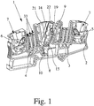
- Fig. 1 shows a terminal block 1 according to the invention in the form of a disconnect terminal, which can be used in particular as a measuring transducer isolating terminal in current transformer measuring circuits of power generation and distribution.
- the terminal block 1 has a generally made of plastic terminal housing 2, in which a two sections 3, 4 existing busbar and two conductor connection elements 5, 6 are arranged.
- the conductor connection elements 5, 6 are formed in the illustrated embodiment as leg spring terminals, in each of which a conductor to be connected can be inserted through a formed in the terminal housing 2 conductor insertion opening 7.
- the conductor connection elements 5, 6 may also be designed as screw terminals, as tension spring terminals or as cutting terminals. With the help of the conductor connection elements 5, 6 can each one electrical conductor to a section 3, 4 of the busbar are connected.
- the conductor connecting elements 5, 6 opposite ends 9, 10 of the sections 3, 4 are bent such that the end 9 of the section 3 is in a plane above the end 10 of the section 4.
- the end 9 of the section 3 is thus bent upward and the end 10 of the section 4 is bent downwards.
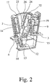
- the first position of the separating knife 8 the end 9 of the first portion 3 of the busbar the separating blade 8 at an upper contact portion 11 and the end 10 of the second portion 4, the separating knife 8 contacted at a lower contact portion 12.
- the ends 9, 10 of the two sections 3, 4 of the busbar are each formed as contact forks 13, between which the respective contact region 11, 12 of the separating blade 8 is inserted in the first position, wherein the contact forks 13 and the separating knife 8 dimensioned are that a safe and good electrical contact is guaranteed.
- the contact fork 13 are bent or arranged to the cutting blade 8, that the contact fork 13 impinge almost perpendicular to the two contact region 11, 12 of the cutting blade 8.
- the longitudinal disconnect switch is pivotally mounted in the terminal housing 2 of the disconnect terminal 1.
- the - in Fig. 4 separately shown - longitudinal disconnector has in addition to the separating knife 8 still an insulating housing 14 which is formed so that at least the upper contact portion 11 and the lower contact portion 12 of the separating blade 8 are not surrounded by the insulating housing 14.
- the connection of separating knife 8 and insulating housing 14 is thereby ensured that the separating knife 8 is encapsulated by the insulating housing 14.
- a pivot pin 15 is integrally formed on a side surface of the insulating housing 14, which is mounted in a corresponding opening 18 in a side wall 16 of the terminal housing 2.
- pivot 15 of the circuit breaker or the insulating housing 14 is also guided by the two side walls 16, 17 of the terminal housing.
- the width of the insulating housing 14 is selected so that it fits tightly in the inserted into the terminal housing 2 state on both side walls 16, 17 of the terminal housing 2.
- the pivot axis of the separating knife 8, that is, the pivot pin 15, between the upper contact portion 11 and the lower contact portion 12 is arranged.
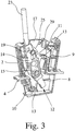
- the second position of the separating knife 8 - as in particular from the Fig. 3 and 7 it can be seen - both the end 9 of the first portion 3 of the busbar from the upper contact portion 11 and the end 10 of the second portion 4 of the busbar from the lower contact portion 12 of the separating blade 8 spaced.
- the two separation lines add up between the end 9 of the first part 3 and the upper contact region 11 on the one hand and the end 10 of the second part 4 and the lower contact region 12 on the other hand to a total separation distance, which ensures a secure separation of the two sections 3, 4 of the busbar.
- the cutting blade 8 is still angled so that the below the pivot axis, ie, below the pivot 5, arranged portion of the cutting blade 8 is bent away from the end 10 of the second section 4, as well as from Fig. 3 and 7 is recognizable.
- a total of an operating angle of only about 30 ° sufficient, so that on the one hand, the middle portion of the terminal 1 - and thus the terminal 1 total -small dimensions, on the other hand, the operation of the circuit breaker very easy and comfortable even in confined spaces is possible.
- a locking pin 19, formed by the separating knife 8 and the longitudinal disconnector both in the first position and in the second position in the terminal housing. 2 is latched.
- two recesses 20 are formed in which the latching pin 19 facing side wall 16 of the terminal housing 2, in which the latching pin 19 is positively locked in the first position or in the second position of the cutting blade 8.
- the positive locking of the locking pin 19 in the two recesses 20 leads, together with the narrow guide of the insulating housing 14 between the two side walls 16, 17 of the terminal housing 2 to the fact that for the fitter the locking both in the first position and in the second position clearly noticeable by an acoustic click.
- the assembly of in Fig. 4 separately shown longitudinal circuit breaker in the terminal housing 2 of the terminal 1 can be done simply by the fact that the circuit breaker is inserted into the terminal housing 2 and locked therein.
- a guide groove 21 is formed in the two side walls 16, 17 of the terminal housing 2, in which when inserting the circuit breaker in the terminal housing 2 on the one of the pivot pin 14 and to another on the opposite side surface of the insulating housing 14 trained corresponding guide pin engages.
- This ensures that the circuit breaker can only be plugged into the terminal housing 2 so that the cutting blade 8 is in the locked state of the insulating housing 14 in the terminal housing 2, first in the second, open position.
- the locking of the insulating housing 14 in the terminal housing 2 takes place in that the pivot pin 15 engages in the opening 18 in the side wall 16 of the terminal housing 2, which is visually and acoustically perceptible by a corresponding click.
- an upwardly open actuating shaft 22 is formed, in which a tool, in particular the tip of a screwdriver 23, can be inserted.
- the actuating shaft 22 is dimensioned so that in him the tip of a screwdriver 23 can be inserted, with which also the conductor connection elements 5, 6 can be operated.
- only a simple screwdriver is needed to connect the conductors and to operate the circuit breaker.
- a symbol 26 is printed, which indicates the respective position of the separating blade 8 in the terminal block 1.
- the longitudinal circuit breaker is in the first, closed position, is printed on the visible in this position end face 24 of the insulating housing 14, the symbol 26 of a closed switch.
- the symbol of an open switch is printed on the opposite end face 25.
- the 6 and 7 show an embodiment of a terminal block 1, in which a shift lock 27 for blocking the circuit breaker 8 in the first position ( Fig. 6 ) or in the second position ( Fig. 7 ) is inserted into the terminal housing 2 and locked therein.
- the shift lock 27 is designed so that after locking into the terminal housing 2 only with a tool, for example, with a pair of needle nose pliers from the terminal housing 2 can be removed, so that an accidental operation of the circuit breaker is reliably prevented.
- the same shift lock 27 can be used both in the first position of the circuit breaker as well as in the second position of the circuit breaker in the terminal housing 2, to which the shift lock 27 must be rotated only by 180 °.
- the shift lock 27 on one side of a locking pin 28 which engages depending on the arrangement of the shift lock 27 in an opening 29 in one side wall 16 or the other side wall 17 of the terminal housing 2.
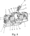
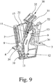
- the operation of the circuit breaker can be done not only by means of a screwdriver 23, but also by means of a switch connection 30, which in the in Fig. 8 illustrated embodiment, two legs 31 and a leg 31 connecting handle portion 32 has.
- a switch connection 30 thus two longitudinal circuit breaker two juxtaposed terminal blocks 1 can be operated simultaneously, for which purpose a leg 31 is inserted into the operating shaft 22 of a longitudinal circuit breaker.
- the terminal blocks 1 shown there have a plurality of guide shafts 33 on both sides of the longitudinal circuit breaker, in which either the contact pins of a test plug, a test socket, a jumper or a jumper can be inserted.
- the contact pins of a test plug, a test socket, a jumper or a jumper can be inserted.
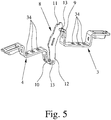
- three openings 34 are formed in the two sections 3, 4 of the busbar ( Fig. 5 ).
Description
Die Erfindung betrifft eine Reihenklemme, insbesondere eine Trennklemme, mit einem Klemmengehäuse, mit einer aus zwei Teilstücken bestehenden Stromschiene, mit zwei Leiteranschlußelementen zum Anschließen von je einem Leiter an ein Teilstück der Stromschiene und mit einem schwenkbar in dem Klemmengehäuse gelagerten Trennmesser, wobei die beiden Teilstücke in einer ersten Stellung des Trennmessers miteinander verbunden und in einer zweiten Stellung des Trennmessers voneinander getrennt sind, und wobei die den Leiteranschlußelementen abgewandten Enden der Teilstücke der Stromschiene derart abgebogen sind, daß in der ersten Stellung des Trennmessers das Ende des ersten Teilstücks der Stromschiene das Trennmesser an einem oberen Kontaktbereich und das Ende des zweiten Teilstücks der Stromschiene das Trennmesser an einem unteren Kontaktbereich kontaktiert. Daneben betrifft die Erfindung noch ein Längstrennschalter mit einem Trennmesser zur schwenkbaren Anordnung in einem Klemmengehäuse einer Reihenklemme.The invention relates to a terminal block, in particular a disconnect terminal, with a terminal housing, with a two-piece busbar, with two conductor connection elements for connecting one conductor to a portion of the busbar and with a pivotally mounted in the terminal housing separating knife, wherein the two sections are connected to each other in a first position of the separating blade and separated from each other in a second position of the separating blade, and wherein the conductor connection elements remote from the ends of the sections of the busbar are bent such that in the first position of the separating blade, the end of the first section of the busbar, the cutting blade at an upper contact portion and the end of the second portion of the bus bar contacts the disconnecting blade at a lower contact area. In addition, the invention also relates to a circuit breaker with a disconnecting blade for pivotal arrangement in a terminal housing a terminal.
Elektrische Reihenklemmen sind seit Jahrzehnten bekannt und werden millionenfach bei der Verdrahtung elektrischer Anlagen und Geräte verwendet. Die Klemmen werden meist auf Tragschienen aufgerastet, welche ihrerseits häufig in einer Mehrzahl in einem Schaltschrank angeordnet sind. Als Leiteranschlußelemente werden in Reihenklemmen überwiegend Schraubklemmen oder Zugfederklemmen verwendet. Daneben können aber auch Schneidanschlußklemmen oder Schenkelfederklemmen verwendet werden.Electrical terminal blocks have been known for decades and are used millions of times in the wiring of electrical systems and equipment. The terminals are usually snapped onto mounting rails, which in turn are often arranged in a plurality in a control cabinet. As conductor connection elements predominantly screw terminals or tension spring terminals are used in terminal blocks. In addition, however, cutting terminals or leg spring terminals can be used.
Der Grundtyp der Reihenklemme ist die Verbindungsklemme, die mindestens zwei Leiteranschlußelemente aufweist, die über eine elektrisch leitende Verbindungsschiene, die Stromschiene, elektrisch miteinander verbunden sind. Neben diesem Grundtyp, der häufig auch als Durchgangsklemme bezeichnet wird, gibt es eine Vielzahl von unterschiedlichen Reihenklemmentypen, die speziell an den jeweiligen Anwendungsfall angepaßt sind. Als Beispiel seien hier Schutzleiterklemmen, Messertrennklemmen und Installationsklemmen genannt.The basic type of terminal block is the connection terminal, which has at least two conductor connection elements, which are electrically connected to one another via an electrically conductive connection rail, the busbar. In addition to this basic type, which is often referred to as a feed-through terminal, there are a variety of different types of terminal blocks, which are specially adapted to the particular application. As an example, protective conductor terminals, knife disconnect terminals and installation terminals may be mentioned here.
Insbesondere bei Reihenklemmen, die in Stromwandler-Meßkreisen der Energieerzeugung und -verteilung eingesetzt werden, sind häufig verschiedene Schalt-, Trenn- und Prüfaufgaben zu realisieren. Entsprechend ihrer Verwendung werden derartige Reihenklemmen häufig auch als Meßwandler-Trennklemmen bezeichnet. Mit Hilfe eines im Klemmengehäuse der Trennklemme angeordneten Längstrennschalters können dabei die beiden Teilstücke der Stromschiene wahlweise miteinander verbunden oder voneinander getrennt werden.In particular, in terminal blocks, which are used in power converter measuring circuits of power generation and distribution, are often different Switching, separating and testing tasks to realize. According to their use, such terminal blocks are often referred to as transducer disconnect terminals. With the help of a arranged in the terminal housing of the disconnect terminal circuit breaker while the two sections of the busbar can either be connected to each other or separated.
Eine elektrische Reihenklemme, bei der zwei Teilstücke einer Stromschiene über eine Trennstelle auftrennbar ist, ist aus der
Aus der
Aus der
Aus der Praxis ist eine eingangs beschriebene Trennklemme bekannt, bei der die Trennstelle von einem schwenkbar im Klemmengehäuse gelagerten Trennmesser gebildet wird. Das Trennmesser ist dabei mit seinem unteren Ende in einer Aufnahme im Klemmengehäuse gelagert, so daß das Trennmesser um diesen Lagerpunkt verschwenkt werden kann. Während das Trennmesser in der ersten Stellung von beiden Teilstücken der Stromschiene kontaktiert wird, kontaktiert das Trennmesser in der zweiten Stellung lediglich eine der beiden Teilstücke, so daß die Stromschiene getrennt ist. Zur Gewährleistung einer ausreichend großen Trennstrecke zwischen dem Trennmesser und dem dem Leiteranschlußelement abgewandten Ende des zweiten Teilstücks ist auch bei dieser Trennklemme ein relativ großer Betätigungswinkel erforderlich.From practice a disconnect terminal described above is known, in which the separation point is formed by a pivotally mounted in the terminal housing separating blade. The cutting knife is mounted with its lower end in a receptacle in the terminal housing, so that the cutting blade can be pivoted about this bearing point. While the separating knife contacted in the first position of both sections of the busbar is, contacted the cutting blade in the second position, only one of the two sections, so that the busbar is disconnected. To ensure a sufficiently large separation distance between the separating knife and the end of the second connecting piece facing away from the conductor connecting element, a relatively large operating angle is also required in the case of this separating clamp.
Darüber hinaus werden in der Praxis häufig Trennschieber als Längstrennschalter verwendet, die axial verschiebbar im Klemmengehäuse angeordnet sind und in der ersten Stellung die beiden Teilstücke der miteinander verbinden. Mit Hilfe einer Schraube wird der Längstrennschalter in seiner jeweiligen Stellung fixiert.In addition, in practice, often slide as a longitudinal disconnector switch are used, which are arranged axially displaceable in the terminal housing and in the first position, the two sections of the interconnect. With the help of a screw, the circuit breaker is fixed in its respective position.
Der vorliegenden Erfindung liegt daher die Aufgabe zugrunde, eine eingangs beschriebene Reihenklemme zur Verfügung zu stellen, bei der das Schalten des Längstrennschalters möglichst platzsparend aber dennoch benutzerfreundlich und sicher möglich ist. Daneben liegt der Erfindung die Aufgabe zugrunde, einen dafür geeigneten Längstrennschalter mit einem Trennmesser zur schwenkbaren Anordnung in einem Klemmengehäuse einer Reihenklemme anzugeben.The present invention is therefore an object of the invention to provide a terminal described above, in which the switching of the circuit breaker space-saving as possible but still user-friendly and safe possible. In addition, the invention has for its object to provide a suitable longitudinal disconnect switch with a separating knife for pivotal arrangement in a terminal housing a terminal.
Diese Aufgabe ist bei der eingangs beschriebenen Reihenklemme dadurch gelöst, daß die Schwenkachse des Trennmessers zwischen dem oberen Kontaktbereich und dem unteren Kontaktbereich angeordnet ist, daß in der zweiten Stellung des Trennmessers sowohl das Ende des ersten Teilstücks der Stromschiene vom oberen Kontaktbereich des Trennmessers als auch das Ende des zweiten Teilstücks der Stromschiene vom unteren Kontaktbereich des Trennmessers beabstandet ist, und daß das Trennmesser derart abgewinkelt ist, daß der unterhalb der Schwenkachse angeordnete Bereich des Trennmessers vom Ende des zweiten Teilstücks der Stromschiene weggebogen ist.This object is achieved in the terminal block described above, characterized in that the pivot axis of the separating knife between the upper contact area and the lower contact area is arranged that in the second position of the separating knife both the end of the first portion of the busbar from the upper contact region of the cutting blade and the End of the second portion of the busbar is spaced from the lower contact region of the separating knife, and that the separating knife is angled such that the arranged below the pivot axis portion of the cutting blade is bent away from the end of the second portion of the busbar.
Durch die Verlagerung der Schwenkachse des Trennmessers vom unteren Ende nach oben erfolgt eine erste Verringerung des erforderlichen Betätigungswinkels zum Verschwenken des Trennmessers aus der ersten Stellung in die zweite Stellung. Zusätzlich ist der erforderliche Betätigungswinkel noch dadurch verringert, daß in der zweiten, offenen Stellung des Trennmessers sowohl das Ende des ersten Teilstücks der Stromschiene vom oberen Kontaktbereich als auch das Ende des zweiten Teilstücks der Stromschiene vom unterenBy the displacement of the pivot axis of the cutting blade from the lower end to the top, a first reduction of the required operating angle for pivoting the cutting blade from the first position to the second position. In addition, the required operating angle is further reduced by the fact that in the second, open position of the cutting blade both the end of the first portion of the busbar from the upper contact area and the end of the second portion of the busbar from the lower
Kontaktbereich des Trennmessers beabstandet ist. Es gibt somit eine Trennstrecken zwischen dem Ende des ersten Teilstücks und dem oberen Kontaktbereich und eine Trennstrecken zwischen dem Ende des zweiten Teilstücks und dem unteren Kontaktbereich, wobei sich beide Trennstrecken zu einer Gesamttrennstrecke addieren, die eine sichere Trennung der beiden Teilstücke der Stromschiene auch bei einem geringen Betätigungswinkel gewährleistet. Damit steht ein Längstrennschalter bzw. ein Trennmesser zur Verfügung, der nur einen relativ geringen Platzbedarf innerhalb des Klemmengehäuses der Reihenklemme beansprucht, so daß die Reihenklemme insgesamt sehr kompakt aufgebaut sein kann.Contact area of the separating knife is spaced. There are thus a separation distances between the end of the first portion and the upper contact area and a separation distances between the end of the second portion and the lower contact area, both separating lines add to a total separation distance, the safe separation of the two sections of the busbar even at a ensures low operating angle. This is a longitudinal circuit breaker or a disconnector available, which requires only a relatively small footprint within the terminal housing of the terminal, so that the terminal can be constructed very compact overall.
Der erforderliche Betätigungswinkel und damit der für das Trennmesser innerhalb der Reihenklemme benötigte Platz kann dadurch weiter reduziert werden, daß erfindungsgemäß das Trennmesser derart abgewinkelt ist, daß der unterhalb der Schwenkachse angeordnete Bereich des Trennmessers vom Ende des zweiten Teilstücks der Stromschiene weggebogen ist. Durch die Geometrie des Trennmessers wird dadurch die Trennstrecke zwischen dem unteren Kontaktbereich und dem Ende des zweiten Teilstücks der Stromschiene vergrößert, so daß zur Gewährleitung einer bestimmten Gesamttrennstrecke zwischen den beiden Teilstücken der Stromschiene ein kleinerer Betätigungswinkel erforderlich ist.The required operating angle and thus the space required for the cutting blade within the terminal block can be further reduced in that the cutting blade according to the invention is angled such that the arranged below the pivot axis of the cutting blade is bent away from the end of the second section of the busbar. Due to the geometry of the separating blade thereby the separation distance between the lower contact region and the end of the second portion of the busbar is increased, so that a smaller operating angle is required to ensure a certain total separation distance between the two sections of the busbar.
Gemäß einer bevorzugten Ausgestaltung der Erfindung ist das Trennmesser teilweise von einem Isoliergehäuse umspritzt, wobei zumindest der obere Kontaktbereich und der untere Kontaktbereich nicht vom Isoliergehäuse umgeben sind und somit von den vorzugsweise als Kontaktgabeln ausgebildeten Enden der beiden Teilstücke in der ersten Stellung des Trennmessers kontaktiert werden können. Gemäß der bevorzugten Ausgestaltung besteht der Längstrennschalter somit aus dem Trennmesser und dem Isoliergehäuse. Dadurch, daß das Trennmesser teilweise vom Isoliergehäuse umspritzt ist, kann sowohl die Betätigung als auch die Montage des Längstrennschalters vereinfacht werden. Vorteilhafterweise ist nämlich das Trennmesser mit dem Isoliergehäuse in das Klemmengehäuse einsteckbar und dort definiert verrastbar.According to a preferred embodiment of the invention, the separating knife is partially encapsulated by an insulating housing, wherein at least the upper contact area and the lower contact area are not surrounded by the insulating housing and thus can be contacted by the preferably designed as contact forks ends of the two sections in the first position of the separating knife , According to the preferred embodiment, the longitudinal disconnector thus consists of the separating blade and the insulating housing. Due to the fact that the separating knife is partially encapsulated by the insulating housing, both the operation and the assembly of the longitudinal circuit breaker can be simplified. Advantageously, namely, the cutting blade with the insulating housing in the terminal housing can be inserted and defined there latched.
Die erfindungsgemäße Reihenklemme kann somit auch als Bausatz bestehend aus dem Klemmengehäuse mit der darin angeordneten, aus zwei Teilstücken bestehende Stromschiene und den Leiteranschlußelemente einerseits und dem Längstrennschalter andererseits vertrieben werden, wobei dann der Längstrennschalter erst bei der Montage der Reihenklemme in das Klemmengehäuse eingerastet wird.The terminal block according to the invention can thus also as a kit consisting of the terminal housing with the arranged therein, of two sections existing busbar and the conductor connection elements on the one hand and the longitudinal circuit breaker on the other hand are sold, in which case the longitudinal circuit breaker is not engaged in the assembly of the terminal block in the terminal housing.
Zur Realisierung der gewünschten Verschwenkbarkeit des Trennmesser innerhalb des Klemmengehäuses ist vorteilhafterweise weiter vorgesehen, daß an zumindest einer Seitenfläche des Isoliergehäuses ein Drehzapfen angeformt ist, der im montierten Zustand des Längstrennschalters in einer Öffnung in einer Seitenwand des Klemmengehäuses einrastet. Die Führung des Isoliergehäuses im Klemmengehäuse kann dadurch weiter verbessert werden, daß das Isoliergehäuse so dimensioniert ist, insbesondere eine solche Breite aufweist, daß es beim Verschwenken aus der ersten Stellung in die zweite Stellung zusätzlich durch die Seitenwände des Klemmengehäuses geführt wird. Zwischen dem Isoliergehäuse und den Seitenwänden des Klemmengehäuses ist dabei vorzugsweise eine leichte Preßpassung realisiert, die ein Verkanten des Isoliergehäuses und damit auch des Trennmessers beim Verschwenken zuverlässig verhindert. Da die Seitenwände des Klemmengehäuses nur eine relativ geringe Wandstärke aufweisen, sind die Seitenwände ausreichend nachgiebig, so daß ein gewolltes Verschwenken des Längstrennschalters aus der ersten Stellung in die zweite Stellung durch die Preßpassung nicht behindert wird.To realize the desired pivotability of the separating knife within the terminal housing is advantageously further provided that on at least one side surface of the insulating housing a pivot is formed, which engages in the mounted state of the longitudinal disconnector in an opening in a side wall of the terminal housing. The leadership of the insulating housing in the terminal housing can be further improved in that the insulating housing is dimensioned, in particular has a width such that it is additionally guided during pivoting from the first position to the second position by the side walls of the terminal housing. Between the insulating housing and the side walls of the terminal housing a slight interference fit is preferably realized, which reliably prevents tilting of the insulating housing and thus also of the separating blade during pivoting. Since the side walls of the terminal housing have only a relatively small wall thickness, the side walls are sufficiently yielding, so that a deliberate pivoting of the longitudinal circuit breaker from the first position to the second position is not hindered by the interference fit.
Gemäß einer weiteren vorteilhaften Ausgestaltung der Erfindung ist vorgesehen, daß eine oder beide Seitenwände des Klemmengehäuses eine Führungsnut aufweisen und daß an zumindest einer Seitenfläche des Isoliergehäuses ein Führungszapfen oder ein Führungssteg ausgebildet ist, wobei die Führungsnut bzw. die Führungsnuten so angeordnet sind, daß das Trennmesser nach dem Einstecken des Isoliergehäuses in das Klemmengehäuse automatisch in der zweiten Stellung angeordnet ist. Durch die Ausbildung der Führungsnuten und der korrespondierenden Führungszapfen oder Führungsstege ist somit gewährleistet, daß der Längstrennschalter nur in einer bestimmten Ausrichtung in das Klemmengehäuse eingesteckt werden kann. Als Führungszapfen, der mit einer Führungsnut in einer Seitenwand des Klemmengehäuses zusammenwirkt, kann dabei vorteilhafterweise der am Isoliergehäuse angeformte Drehzapfen dienen.According to a further advantageous embodiment of the invention it is provided that one or both side walls of the terminal housing have a guide groove and that on at least one side surface of the insulating housing, a guide pin or a guide web is formed, wherein the guide groove or the guide grooves are arranged so that the separating knife is automatically arranged in the second position after insertion of the insulating housing in the terminal housing. The formation of the guide grooves and the corresponding guide pins or guide webs thus ensures that the longitudinal circuit breaker can be inserted only in a certain orientation in the terminal housing. As a guide pin, which cooperates with a guide groove in a side wall of the terminal housing, can advantageously serve the molded on the insulating pivot.
Gemäß einer weiteren vorteilhaften Ausgestaltung der Erfindung ist vorgesehen, daß das Isoliergehäuse des Längstrennschalters an mindestens einer Seitenfläche einen Rastzapfen aufweist und daß in der korrespondierenden Seitenwand des Klemmengehäuses zwei zum Rastzapfen korrespondierende Ausnehmungen ausgebildet sind, in denen der Rastzapfen in der ersten Stellung bzw. in der zweiten Stellung des Trennmessers verrastet. Der Rastzapfen und die Ausnehmungen sind dabei vorteilhafterweise so ausgebildet, daß sowohl in der ersten Stellung als auch in der zweiten Stellung des Trennmessers eine formschlüssige Verrastung erfolgt, wobei das Einrasten des Rastzapfens in die Ausnehmung durch ein akustisches Klicken deutlich feststellbar ist.According to a further advantageous embodiment of the invention it is provided that the insulating housing of the circuit breaker on at least one side surface has a locking pin and that in the corresponding side wall of the terminal housing two recesses corresponding to the locking pin are formed, in which the locking pin in the first position or in the locked second position of the cutting knife. The locking pin and the recesses are advantageously designed so that both in the first position and in the second position of the separating knife a positive locking takes place, wherein the engagement of the locking pin in the recess by an acoustic click is clearly noticeable.
Zur einfachen Betätigung des Längstrennschalters, d.h. zur Verschwenkung des Trennmessers aus der ersten Stellung in die zweite Stellung, ist im Isoliergehäuse ein nach oben offener Betätigungsschacht ausgebildet, in den ein Werkzeug, insbesondere die Spitze eines Schraubendrehers, eingesteckt werden kann. Durch die dadurch erzielte Verlängerung des Hebelarmes kann das Trennmesser einfach aus der einen, verrasteten Stellung in die andere, ebenfalls verrastete Stellung verschwenkt werden. Der Betätigungsschacht ist dabei vorzugsweise so dimensioniert, daß zum Verschwenken des Längstrennschalters ein Schraubendreher verwendet werden kann, mit dem auch die Leiteranschlußelemente betätigt, d.h. geöffnet oder geschlossen werden können. Darüber hinaus verläuft der Betätigungsschacht vorzugsweise seitlich versetzt zum oberhalb der Schwenkachse angeordneten Bereich des Trennmessers. Dadurch kann der Betätigungsschacht eine große Tiefe aufweisen, wodurch die Spitze eines Schraubendrehers sicher geführt ist, ohne daß das Isoliergehäuse wesentlich über das obere Ende des Trennmessers hinausragen muß.For easy operation of the circuit breaker, i. for pivoting the separating blade from the first position to the second position, an open-topped actuating shaft is formed in the insulating housing, in which a tool, in particular the tip of a screwdriver, can be inserted. By thus achieved extension of the lever arm, the cutting blade can be easily pivoted from one, latched position to the other, also latched position. The actuating shaft is preferably dimensioned so that the pivoting of the longitudinal circuit breaker, a screwdriver can be used with which also operates the conductor connection elements, i. can be opened or closed. In addition, the actuating shaft preferably extends laterally offset to the above the pivot axis arranged region of the cutting blade. As a result, the actuating shaft can have a large depth, whereby the tip of a screwdriver is guided safely without the insulating housing must protrude substantially beyond the upper end of the cutting blade.
Die Ausbildung des Betätigungsschachts im Isoliergehäuse schafft darüber hinaus die Möglichkeit, bei mehreren nebeneinander angeordneten Reihenklemmen deren Längstrennschalter gleichzeitig zu betätigen, in dem eine Schalterverbindung verwendet wird, die mindestens zwei Schenkel und einen die Schenkel verbindenden Griffabschnitt aufweist. Die einzelnen Schenkeln der Schalterverbindung sind dabei so ausgebildet, daß sie jeweils in einen Betätigungsschacht eingesteckt und vorzugsweise auch verrasten können. Dadurch können mit einem einzigen Handgriff gleichzeitig mehrere Längstrennschalter mehrerer Reihenklemmen geschaltet werden.The formation of the actuating shaft in the insulating housing also creates the possibility to operate at several juxtaposed terminal blocks whose circuit breaker at the same time, in which a switch connection is used which has at least two legs and a leg connecting the handle portion. The individual legs of the switch connection are designed so that they can each be inserted into an operating shaft and preferably also lock. As a result, several longitudinal disconnectors of several terminal blocks can be switched simultaneously with a single movement.
Gemäß einer letzten vorteilhaften Ausgestaltung der erfindungsgemäßen Reihenklemme, die hier noch kurz erläutert werden soll, ist eine Schaltsperre vorgesehen, die zur Blockierung des Trennmessers in der einen und/oder der anderen Stellung in das Klemmengehäuse eingesteckt und darin verrastet werden kann. Die Schaltsperre ist dabei vorzugsweise so ausgebildet, daß sie lediglich um 180° gedreht werden muß, um in der einen oder der anderen Stellungen des Trennmessers in das Klemmengehäuse eingesteckt werden zu können. Darüber hinaus ist vorteilhafterweise vorgesehen, daß die Schaltsperre eine im eingesteckten Zustand dem Isoliergehäuse zugewandte offene Stirnseite aufweist, so daß auch bei eingesteckter Schaltsperre ein auf einer Stirnseite des Kunststoffgehäuses aufgedrucktes Symbol zur Kennzeichnung der Stellung des Trennmessers von oben durch die Schaltsperre sichtbar ist.According to a last advantageous embodiment of the terminal block according to the invention, which will be briefly explained here, a shift lock is provided, which can be plugged into the terminal housing and locked therein to block the cutting blade in one and / or the other position. The shift lock is preferably designed so that it only needs to be rotated by 180 ° in order to be able to be plugged into the terminal housing in one or the other positions of the cutting blade. In addition, it is advantageously provided that the switching lock has a plugged in the insulating housing facing the open end, so that even when plugged lockout on a front side of the plastic housing printed symbol for indicating the position of the cutting blade from above by the shift lock is visible.
Bei dem eingangs genannten Längstrennschalter ist die Aufgabe mit den Merkmalen des Patentanspruchs 13 dadurch gelöst, daß die Schwenkachse des Trennmessers zwischen dem oberen Kontaktbereich und dem unteren Kontaktbereich angeordnet ist und daß in einer zweiten Stellung des Trennmessers sowohl der obere Kontaktbereich des Trennmessers von dem Ende des ersten Teilstücks der Stromschiene als auch der untere Kontaktbereich des Trennmessers von dem Ende des zweiten Teilstücks der Stromschiene beabstandet ist. Bezüglich der Vorteile und vorteilhaften Ausgestaltungen des Längstrennschalters wird auf die Patentansprüche 14 bis 17 sowie die vorherigen Ausführungen zur erfindungsgemäßen Reihenklemme verwiesen.In the case of the above-mentioned longitudinal disconnect switch, the object with the features of
Im einzelnen gibt es nun eine Vielzahl von Möglichkeiten, die erfindungsgemäße Reihenklemme auszugestalten und weiterzubilden. Dazu wird verwiesen sowohl auf die dem Patentanspruch 1 nachgeordneten Patentansprüche, als auch auf die nachfolgende Beschreibung bevorzugter Ausführungsbeispiele in Verbindung mit Zeichnung. In der Zeichnung zeigen
- Fig. 1
- eine perspektivische Darstellung einer erfindungsgemäßen Reihenklemme, mit teilweise weggelassener Seitenwand,
- Fig. 2
- eine vergrößerte Darstellung des mittleren Bereichs der Reihenklemme gemäß
Fig. 1 , mit einem Längstrennschalter in der ersten Stellung, - Fig. 3
- eine vergrößerte Darstellung des mittleren Bereichs der Reihenklemme gemäß
Fig. 1 , mit einem Längstrennschalter in der zweiten Stellung, - Fig. 4
- eine separate Darstellung des Längstrennschalters,
- Fig. 5
- die beiden über das Trennmesser elektrisch miteinander verbundenen Teilstücke der Stromschiene einer Reihenklemme,
- Fig. 6
- eine vergrößerte Darstellung des mittleren Bereichs der Reihenklemme, mit einem Längstrennschalter in der ersten Stellung und einer eingesetzten Schaltsperre,
- Fig. 7
- eine vergrößerte Darstellung des mittleren Bereichs der Reihenklemme, mit einem Längstrennschalter in der zweiten Stellung und einer eingesetzten Schaltsperre,
- Fig. 8
- eine perspektivische Darstellung zweier benachbart auf einer Tragschiene angeordneter Reihenklemmen, und
- Fig. 9
- eine Schnittdarstellung durch den mittleren Bereich einer Reihenklemme gemäß
Fig. 8 , mit eingesteckter Schalterverbindung.
- Fig. 1
- a perspective view of a terminal block according to the invention, with partially omitted side wall,
- Fig. 2
- an enlarged view of the central region of the terminal according to
Fig. 1 , with a longitudinal circuit breaker in the first position, - Fig. 3
- an enlarged view of the central region of the terminal according to
Fig. 1 , with a longitudinal circuit breaker in the second position, - Fig. 4
- a separate representation of the longitudinal circuit breaker,
- Fig. 5
- the two sections of the busbar of a terminal block which are electrically connected to one another via the separating knife,
- Fig. 6
- an enlarged view of the central region of the terminal, with a longitudinal circuit breaker in the first position and an inserted shift lock,
- Fig. 7
- an enlarged view of the central region of the terminal, with a circuit breaker in the second position and an inserted shift lock,
- Fig. 8
- a perspective view of two adjacent arranged on a support rail terminal blocks, and
- Fig. 9
- a sectional view through the middle region of a terminal according to
Fig. 8 , with inserted switch connection.
Bei der in der
Wie aus den Figuren, insbesondere den
Dabei sind die Enden 9, 10 der beiden Teilstücke 3, 4 der Stromschiene jeweils als Kontaktgabeln 13 ausgebildet, zwischen die der jeweilige Kontaktbereich 11, 12 des Trennmessers 8 in der ersten Stellung eingesteckt ist, wobei die Kontaktgabeln 13 bzw. das Trennmesser 8 so dimensioniert sind, daß eine sichere und gute elektrische Kontaktierung gewährleistet ist. Außerdem sind die Kontaktgabel 13 so abgebogen bzw. zum Trennmesser 8 angeordnet, daß die Kontaktgabel 13 nahezu lotrecht auf die beiden Kontaktbereich 11, 12 des Trennmessers 8 auftreffen. Dadurch wird der Verschließ auf der Oberfläche des Trennmessers 8 minimiert bzw. eine auf der Oberfläche des Trennmessers 8 aufgebrachte Kontaktschicht nur geringfügig verkratzt.The ends 9, 10 of the two
Zuvor ist ausgeführt worden, daß der Längstrennschalter schwenkbar im Klemmengehäuse 2 der Trennklemme 1 angeordnet ist. Der - in
Zusätzlich zur Lagerung über den in der Öffnung 18 eingerasteten Drehzapfen 15 ist der Längstrennschalter bzw. das Isoliergehäuse 14 auch durch die beiden Seitenwände 16, 17 des Klemmengehäuses geführt. Hierzu ist die Breite des Isoliergehäuses 14 so gewählt, daß es im in das Klemmengehäuse 2 eingesetzten Zustand an beiden Seitenwänden 16, 17 des Klemmengehäuses 2 eng anliegt. Durch diese zusätzliche seitliche Führung des Isoliergehäuses 14 an den Seitenwänden 16, 17 des Klemmengehäuses 2 ist die Ausbildung nur eines Drehzapfens 15 auf einer Seite des Isoliergehäuses 14 ausreichend. Dies führt dazu, daß die zweite Seitenwand 17 des Klemmengehäuses geschlossen sein kann, wodurch die Einhaltung der erforderlichen Luft- und Kriechstrecken einfacher sichergestellt werden kann.In addition to storage over the locked in the
Bei der erfindungsgemäßen Reihenklemme 1 ist die Schwenkachse des Trennmessers 8, d.h. der Drehzapfen 15, zwischen dem oberen Kontaktbereich 11 und dem unteren Kontaktbereich 12 angeordnet. Dies führt dazu, daß der benötigte Betätigungswinkel zum Verschwenken des Trennmessers 8 aus der ersten Stellung in die zweite Stellung im Vergleich zu einer Drehlagerung des Trennmessers an dessen unteren Ende verringert ist. Zusätzlich sind in der zweiten Stellung des Trennmessers 8 - wie insbesondere aus den
Schließlich ist bei dem dargestellten bevorzugten Ausführungsbeispiel das Trennmesser 8 noch derart abgewinkelt, daß der unterhalb der Schwenkachse, d.h. unterhalb des Drehzapfens 5, angeordnete Bereich des Trennmessers 8 vom Ende 10 des zweiten Teilstücks 4 weggebogen ist, wie ebenfalls aus den
Im oberen Bereich des Isoliergehäuses 14 ist auf der selben Seite, auf der sich der Drehzapfen 15 befindet, zusätzlich noch ein Rastzapfen 19 angeformt, durch den das Trennmesser 8 bzw. der Längstrennschalter sowohl in der ersten Stellung als auch in der zweiten Stellung im Klemmengehäuse 2 verrastbar ist. Dazu sind in der dem Rastzapfen 19 zugewandten Seitenwand 16 des Klemmengehäuses 2 zwei Ausnehmungen 20 ausgebildet, in denen der Rastzapfen 19 in der ersten Stellung bzw. in der zweiten Stellung des Trennmessers 8 formschlüssig verrastet. Die formschlüssige Verrastung des Rastzapfens 19 in den beiden Ausnehmungen 20 führt dabei zusammen mit der engen Führung des Isoliergehäuses 14 zwischen den beiden Seitenwänden 16, 17 des Klemmengehäuses 2 dazu, daß für den Monteur die Verrastung sowohl in der ersten Stellung als auch in der zweiten Stellung durch ein akustisches Klicken deutlich feststellbar ist.In the upper region of the insulating
Die Montage des in
Um das Verschwenken des Längstrennschalters aus der einen Stellung in die andere Stellung zu erleichtern, ist in dem Isoliergehäuse 14 ein nach oben offener Betätigungsschacht 22 ausgebildet, in den ein Werkzeug, insbesondere die Spitze eines Schraubendrehers 23, eingesteckt werden kann. Der Betätigungsschacht 22 ist dabei so dimensioniert, daß in ihn die Spitze eines Schraubendrehers 23 eingesteckt werden kann, mit dem auch die Leiteranschlußelemente 5, 6 betätigt werden können. Zum Anschließen der Leiter und zum Betätigen des Längstrennschalters wird somit nur ein einfacher Schraubendreher benötigt.In order to facilitate the pivoting of the longitudinal circuit breaker from one position to the other position, in the insulating
Den
Die
Wie aus den
Aus den
Claims (12)
- Modular terminal, in particular an isolating terminal, with a terminal housing (2), with a busbar consisting of two sections (3, 4), with two terminal elements (5, 6) for connecting one conductor at a time to a section (3, 4) of the busbar, and with an isolating blade (8) supported pivotally in the terminal housing (2),
wherein the two sections (3, 4) are connected to one another in a first position of the isolating blade (8) and are separated from one another in a second position of the isolating blade (8), and
wherein the ends (9, 10) of the sections (3, 4) of the busbar facing away from the terminal elements (5, 6) are bent such that, in the first position of the isolating blade (8), the end (9) of the first section (3) of the busbar makes contact with the isolating blade (8) at an upper contact region (11) and the end (9) of the second section (4) of the busbar makes contact with the isolating blade (8) at a lower contact region (12),
characterized in
that the pivot axis of the isolating blade (8) is arranged between the upper contact region (11) and the lower contact region (12),
that, in the second position of the isolating blade (8), both the end (9) of the first section (3) of the busbar is spaced apart from the upper contact region (11) of the isolating blade (8) and the end (10) of the second section (4) of the busbar is spaced apart from the lower contact region (12) of the isolating blade (8), and
that the isolating blade (8) is angled such that the region of the isolating blade (8) located below the pivot axis is bent away from the end (10) of the second section (4) of the busbar. - Modular terminal according to claim 1, characterized in that the ends (9, 10) of the two sections (3, 4) of the busbar are designed as contact forks (13).
- Modular terminal according to claim 1 or 2, characterized in that the isolating blade (8) is partially surrounded by an insulating housing (14), wherein at least the upper contact region (11) and the lower contact region (12) not being surrounded by the insulating housing (14), and
that the insulating housing (14) has a pivot (15) on a side surface and a corresponding opening (18) is formed in a side wall (16) of the terminal housing (2). - Modular terminal according to claim 3, characterized in that the isolating blade (8) can be locked both in the first position and in the second position, for which the insulating housing (14) has a catch journal (19) on one side surface and two corresponding recesses (20) are formed in a side wall (16) of the terminal housing (2), in which recesses the catch journal (19) locks in the first position and in the second position of the isolating blade (8).
- Modular terminal according to claim 4, characterized in that the insulating housing (14) of the isolating blade (8) is dimensioned such that the insulating housing (14) is guided by the side walls (16, 17) of the terminal housing (2) when pivoted out of the first position into the second position.
- Modular terminal according to claim 5, characterized in that the isolating blade (8) with the insulating housing (14) can be inserted into the terminal housing (2) and can be locked in the insulating housing (14), wherein preferably one or both side walls (16, 17) of the terminal housing (2) has a guide groove (21), wherein the guide groove (21) or the guide grooves (21) are arranged such that the isolating blade (8) is arranged in the second position after insertion.
- Modular terminal according to any one of claims 3 to 6, characterized in that the insulating housing (14) has an actuating slot (22) that is open to the top and into which a tool, especially the tip of a screwdriver (23), can be inserted, wherein the actuating slot (22) preferably runs laterally offset to the region of the isolating blade (8) which is located above the pivoting axis.
- Modular terminal according to any one of claims 3 to 7, characterized in that a symbol (26) for the respective position of the isolating blade (8) is applied on both end faces (24, 25) of the insulating housing (14) in such a manner that the symbol (26) can be seen when looking at the top of the terminal housing (2).
- Modular terminal according to any one of claims 1 to 8, characterized in that a lockout device (27) can be inserted into the terminal housing (2) for blocking the isolating blade (8) in the first and/or second position, wherein the lockout device (27) preferably can be locked in the terminal housing (2) such that the lockout device (27) can only be removed from the terminal housing (2) again with a tool.
- Modular terminal according to claims 8 and 9, characterized in that the end face of the lockout device (27) facing the insulating housing (14) in the inserted state of the lockout device (27) is open or transparent, so that the symbol (26) on the insulating housing (14) can be seen from overhead even when the lockout device (27) is inserted.
- Modular terminal according to any one of the claims 7 to 10, characterized in that a switch connection (30), which has at least two legs (31) and a grip section (32) connecting the legs (31), can be inserted with one leg (31) into the actuating slot (22) in the insulating housing (14).
- Modular terminal according to any one of claims 1 to 11, characterized in that the terminal housing (2) has several guide slots (33) and that several openings (34) are formed in the two sections (3, 4) of the busbar for inserting a contact pin of a test plug, a test socket, a plug-in jumper or a jumper.
Applications Claiming Priority (2)
| Application Number | Priority Date | Filing Date | Title |
|---|---|---|---|
| DE102008014176A DE102008014176B4 (en) | 2008-03-14 | 2008-03-14 | Terminal block, in particular isolating terminal, and circuit breaker |
| PCT/EP2009/001792 WO2009112264A1 (en) | 2008-03-14 | 2009-03-12 | Modular terminal, particularly isolating terminal |
Publications (2)
| Publication Number | Publication Date |
|---|---|
| EP2255369A1 EP2255369A1 (en) | 2010-12-01 |
| EP2255369B1 true EP2255369B1 (en) | 2018-11-14 |
Family
ID=40796328
Family Applications (1)
| Application Number | Title | Priority Date | Filing Date |
|---|---|---|---|
| EP09720012.5A Active EP2255369B1 (en) | 2008-03-14 | 2009-03-12 | Modular terminal, particularly disconnect terminal |
Country Status (7)
| Country | Link |
|---|---|
| US (1) | US8581131B2 (en) |
| EP (1) | EP2255369B1 (en) |
| JP (1) | JP5542698B2 (en) |
| CN (1) | CN102027559B (en) |
| DE (1) | DE102008014176B4 (en) |
| ES (1) | ES2703758T3 (en) |
| WO (1) | WO2009112264A1 (en) |
Families Citing this family (23)
| Publication number | Priority date | Publication date | Assignee | Title |
|---|---|---|---|---|
| DE102008014177A1 (en) * | 2008-03-14 | 2009-09-17 | Phoenix Contact Gmbh & Co. Kg | Terminal block and terminal block |
| DE102010033808B4 (en) * | 2010-08-09 | 2016-12-22 | Phoenix Contact Gmbh & Co. Kg | terminal |
| DE102010052871B4 (en) * | 2010-12-01 | 2014-06-05 | Phoenix Contact Gmbh & Co. Kg | terminal |
| DE102011105157B4 (en) * | 2011-06-17 | 2019-01-03 | Phoenix Contact Gmbh & Co. Kg | Electrical connection module with interruptible circuit and method for detecting a current strength |
| DE102012010244A1 (en) * | 2012-05-24 | 2013-11-28 | Phoenix Contact Gmbh & Co. Kg | Electrical connection terminal |
| USD701176S1 (en) * | 2012-07-31 | 2014-03-18 | Phoenix Contact Gmbh & Co. Kg | Socket module for an electronic relay |
| DE102012107264A1 (en) * | 2012-08-08 | 2014-02-13 | Phoenix Contact Gmbh & Co. Kg | connection module |
| DE102014102602A1 (en) * | 2014-02-27 | 2015-08-27 | Phoenix Contact Gmbh & Co. Kg | Terminal block and terminal block |
| DE102015103113A1 (en) * | 2015-03-04 | 2016-09-08 | Phoenix Contact Gmbh & Co. Kg | Disconnect terminal |
| US9396889B1 (en) * | 2015-04-03 | 2016-07-19 | Eaton Corporation | Electrical switching apparatus and secondary disconnect assembly with cradle assembly alignment and positioning features therefor |
| DE102015121057A1 (en) | 2015-12-03 | 2017-06-08 | Phoenix Contact Gmbh & Co. Kg | Electrical terminal |
| DE202016101051U1 (en) * | 2016-02-29 | 2017-05-30 | Wago Verwaltungsgesellschaft Mbh | terminal |
| DE102016004884B4 (en) * | 2016-04-22 | 2020-06-04 | Sew-Eurodrive Gmbh & Co Kg | Drive system with an intermediate circuit busbar |
| TWI619317B (en) * | 2016-06-20 | 2018-03-21 | Improved structure of the connector head limiter of the wire connection terminal | |
| JP6733368B2 (en) * | 2016-06-29 | 2020-07-29 | オムロン株式会社 | Terminal connection mechanism and switch |
| USD901400S1 (en) * | 2017-03-07 | 2020-11-10 | Phoenix Contact Gmbh & Co. Kg | Electrical connector |
| JP1623945S (en) * | 2018-03-14 | 2019-02-04 | ||
| JP1623420S (en) * | 2018-03-14 | 2019-02-04 | ||
| DE102018133438A1 (en) * | 2018-12-21 | 2020-06-25 | Weidmüller Interface GmbH & Co. KG | Disconnect terminal |
| DE102019112243B4 (en) * | 2019-05-10 | 2022-10-06 | Phoenix Contact Gmbh & Co. Kg | Test adapter with switching lock and the associated test arrangement |
| DE102019123285A1 (en) * | 2019-08-30 | 2021-03-04 | Weidmüller Interface GmbH & Co. KG | Arrangement of disconnect terminals with coupling device, disconnect terminal with coupling device, and disconnect terminal with switching status display |
| DE102020106323A1 (en) | 2020-03-09 | 2021-09-09 | Weidmüller Interface GmbH & Co. KG | Arrangement of isolating terminals with plug-in unit and method for short-circuiting such an arrangement |
| CN113192789B (en) * | 2021-03-24 | 2023-05-12 | 天津平高智能电气有限公司 | Column isolating switch and wiring terminal thereof |
Citations (1)
| Publication number | Priority date | Publication date | Assignee | Title |
|---|---|---|---|---|
| DE4444551A1 (en) * | 1994-12-01 | 1996-06-05 | Wago Verwaltungs Gmbh | Current transformer disconnection terminal |
Family Cites Families (19)
| Publication number | Priority date | Publication date | Assignee | Title |
|---|---|---|---|---|
| US2620415A (en) | 1949-05-04 | 1952-12-02 | Ohio Brass Co | Knife blade switch |
| DE1490497B2 (en) * | 1963-12-14 | 1971-02-11 | Siemens AG 1000 Berlin u 8000 München | Terminal block as an isolating terminal |
| US3676629A (en) * | 1971-04-05 | 1972-07-11 | S & C Electric Co | Switch construction with non-bounce contacts |
| US3840717A (en) * | 1973-08-20 | 1974-10-08 | Gen Electric | Manually operated rotary switch and combination load contact-fuse clip therefor |
| JPS55154028A (en) * | 1979-05-21 | 1980-12-01 | Hitachi Ltd | Circuit breaker |
| JPS57143547U (en) * | 1981-03-02 | 1982-09-09 | ||
| ATE94311T1 (en) * | 1989-03-04 | 1993-09-15 | Weidmueller Interface | DOUBLE DISCONNECT CLAMP. |
| DE4106555A1 (en) | 1990-03-02 | 1991-09-05 | Phoenix Elekt | Electrical rail mounted terminal block - has connections coupled to isolating elements accessible from top of unit |
| JPH05336621A (en) * | 1992-05-28 | 1993-12-17 | Fuji Electric Co Ltd | Mounting structure for circuit breaker |
| DE9315474U1 (en) * | 1993-10-09 | 1994-01-13 | Wago Verwaltungs Gmbh | Electrical terminal with a busbar connection |
| JP3228002B2 (en) * | 1994-06-08 | 2001-11-12 | 株式会社日立製作所 | Circuit breaker |
| DE4444556A1 (en) * | 1994-12-01 | 1996-06-05 | Wago Verwaltungs Gmbh | Switchable terminal block fitted to supporting rail |
| US5669788A (en) * | 1996-09-18 | 1997-09-23 | Allen-Bradley Company, Inc. | Screwless terminal block linking apparatus |
| JP3997818B2 (en) * | 2001-05-28 | 2007-10-24 | 富士電機機器制御株式会社 | Circuit breaker for wiring |
| CN2708478Y (en) * | 2004-04-01 | 2005-07-06 | 王世孝 | Large capacity isolating switch |
| US7005594B2 (en) * | 2004-04-16 | 2006-02-28 | Ls Industrial Systems Co., Ltd. | Movable contactor assembly of circuit breaker |
| US7189935B1 (en) * | 2005-12-08 | 2007-03-13 | General Electric Company | Contact arm apparatus and method of assembly thereof |
| DE102008014179B4 (en) * | 2008-03-14 | 2012-08-02 | Phoenix Contact Gmbh & Co. Kg | Switching bridge and assembly consisting of at least two electrical terminal blocks and a jumper |
| DE102008014177A1 (en) * | 2008-03-14 | 2009-09-17 | Phoenix Contact Gmbh & Co. Kg | Terminal block and terminal block |
-
2008
- 2008-03-14 DE DE102008014176A patent/DE102008014176B4/en not_active Expired - Fee Related
-
2009
- 2009-03-12 CN CN200980117097.1A patent/CN102027559B/en active Active
- 2009-03-12 ES ES09720012T patent/ES2703758T3/en active Active
- 2009-03-12 JP JP2010550089A patent/JP5542698B2/en not_active Expired - Fee Related
- 2009-03-12 US US12/922,633 patent/US8581131B2/en active Active
- 2009-03-12 WO PCT/EP2009/001792 patent/WO2009112264A1/en active Application Filing
- 2009-03-12 EP EP09720012.5A patent/EP2255369B1/en active Active
Patent Citations (1)
| Publication number | Priority date | Publication date | Assignee | Title |
|---|---|---|---|---|
| DE4444551A1 (en) * | 1994-12-01 | 1996-06-05 | Wago Verwaltungs Gmbh | Current transformer disconnection terminal |
Also Published As
| Publication number | Publication date |
|---|---|
| JP5542698B2 (en) | 2014-07-09 |
| EP2255369A1 (en) | 2010-12-01 |
| US20110062011A1 (en) | 2011-03-17 |
| US8581131B2 (en) | 2013-11-12 |
| DE102008014176A1 (en) | 2009-09-17 |
| CN102027559A (en) | 2011-04-20 |
| WO2009112264A1 (en) | 2009-09-17 |
| JP2011517500A (en) | 2011-06-09 |
| CN102027559B (en) | 2014-08-20 |
| ES2703758T3 (en) | 2019-03-12 |
| DE102008014176B4 (en) | 2011-01-27 |
Similar Documents
| Publication | Publication Date | Title |
|---|---|---|
| EP2255369B1 (en) | Modular terminal, particularly disconnect terminal | |
| EP2255409B1 (en) | Jumper, and structural unit comprising at least two modular electric terminals and a jumper | |
| EP2255410B1 (en) | Modular terminal, and modular terminal block | |
| EP1753087B1 (en) | ELECTRICAL terminal | |
| EP1251590B1 (en) | Electrical terminal | |
| EP2839544B1 (en) | Test terminal block | |
| DE102008057754B4 (en) | Assembly of at least two juxtaposed separating terminals and at least two interconnected terminal plugs | |
| EP2965389B1 (en) | Connection terminal | |
| EP3176879B1 (en) | Electrical terminal | |
| DE10045498A1 (en) | Electrical terminal block | |
| EP1811604A2 (en) | Electrical terminal block | |
| EP1529302A1 (en) | Electrical switchgear | |
| DE102015102257B4 (en) | Electrical terminal block and connector system for terminal blocks with an operating or test plug | |
| EP0984513B1 (en) | Insertion piece for an industrial connector | |
| EP2819246B1 (en) | Connection device, in particular switching device, with a spring-loaded terminal and a drive mechanism for operating the spring-loaded terminal | |
| EP3671785A1 (en) | Arrangement of a carrier and an upper part of a switching device with components in an electronics system integrated in the arrangement | |
| EP1523065B1 (en) | Electrical terminal | |
| DE102008014180B4 (en) | Disconnect terminal, in particular neutral disconnect terminal | |
| EP3590153B1 (en) | Terminal block arrangement | |
| EP3698440A1 (en) | Fastening clamp | |
| DE102006008971B4 (en) | Function plug and assembly consisting of two electrical terminal blocks and a functional plug | |
| WO2009030719A1 (en) | Switch having at least two switch levels | |
| WO2016162404A1 (en) | Power converter system and load interrupter comprising such a power converter system | |
| DE102008011217A1 (en) | Operating tool for attaching insulated conductor to cutting element in terminal socket, has insulated conductor for running by rotation movement of operating aid from one position into another position |
Legal Events
| Date | Code | Title | Description |
|---|---|---|---|
| PUAI | Public reference made under article 153(3) epc to a published international application that has entered the european phase |
Free format text: ORIGINAL CODE: 0009012 |
|
| 17P | Request for examination filed |
Effective date: 20101014 |
|
| AK | Designated contracting states |
Kind code of ref document: A1 Designated state(s): AT BE BG CH CY CZ DE DK EE ES FI FR GB GR HR HU IE IS IT LI LT LU LV MC MK MT NL NO PL PT RO SE SI SK TR |
|
| AX | Request for extension of the european patent |
Extension state: AL BA RS |
|
| DAX | Request for extension of the european patent (deleted) | ||
| 17Q | First examination report despatched |
Effective date: 20140520 |
|
| GRAP | Despatch of communication of intention to grant a patent |
Free format text: ORIGINAL CODE: EPIDOSNIGR1 |
|
| STAA | Information on the status of an ep patent application or granted ep patent |
Free format text: STATUS: GRANT OF PATENT IS INTENDED |
|
| INTG | Intention to grant announced |
Effective date: 20180522 |
|
| GRAS | Grant fee paid |
Free format text: ORIGINAL CODE: EPIDOSNIGR3 |
|
| GRAA | (expected) grant |
Free format text: ORIGINAL CODE: 0009210 |
|
| STAA | Information on the status of an ep patent application or granted ep patent |
Free format text: STATUS: THE PATENT HAS BEEN GRANTED |
|
| AK | Designated contracting states |
Kind code of ref document: B1 Designated state(s): AT BE BG CH CY CZ DE DK EE ES FI FR GB GR HR HU IE IS IT LI LT LU LV MC MK MT NL NO PL PT RO SE SI SK TR |
|
| REG | Reference to a national code |
Ref country code: GB Ref legal event code: FG4D Free format text: NOT ENGLISH |
|
| REG | Reference to a national code |
Ref country code: CH Ref legal event code: EP Ref country code: AT Ref legal event code: REF Ref document number: 1065838 Country of ref document: AT Kind code of ref document: T Effective date: 20181115 |
|
| REG | Reference to a national code |
Ref country code: DE Ref legal event code: R096 Ref document number: 502009015454 Country of ref document: DE |
|
| REG | Reference to a national code |
Ref country code: IE Ref legal event code: FG4D Free format text: LANGUAGE OF EP DOCUMENT: GERMAN |
|
| REG | Reference to a national code |
Ref country code: ES Ref legal event code: FG2A Ref document number: 2703758 Country of ref document: ES Kind code of ref document: T3 Effective date: 20190312 |
|
| REG | Reference to a national code |
Ref country code: NL Ref legal event code: MP Effective date: 20181114 |
|
| REG | Reference to a national code |
Ref country code: LT Ref legal event code: MG4D |
|
| PG25 | Lapsed in a contracting state [announced via postgrant information from national office to epo] |
Ref country code: LV Free format text: LAPSE BECAUSE OF FAILURE TO SUBMIT A TRANSLATION OF THE DESCRIPTION OR TO PAY THE FEE WITHIN THE PRESCRIBED TIME-LIMIT Effective date: 20181114 Ref country code: HR Free format text: LAPSE BECAUSE OF FAILURE TO SUBMIT A TRANSLATION OF THE DESCRIPTION OR TO PAY THE FEE WITHIN THE PRESCRIBED TIME-LIMIT Effective date: 20181114 Ref country code: BG Free format text: LAPSE BECAUSE OF FAILURE TO SUBMIT A TRANSLATION OF THE DESCRIPTION OR TO PAY THE FEE WITHIN THE PRESCRIBED TIME-LIMIT Effective date: 20190214 Ref country code: NO Free format text: LAPSE BECAUSE OF FAILURE TO SUBMIT A TRANSLATION OF THE DESCRIPTION OR TO PAY THE FEE WITHIN THE PRESCRIBED TIME-LIMIT Effective date: 20190214 Ref country code: LT Free format text: LAPSE BECAUSE OF FAILURE TO SUBMIT A TRANSLATION OF THE DESCRIPTION OR TO PAY THE FEE WITHIN THE PRESCRIBED TIME-LIMIT Effective date: 20181114 Ref country code: IS Free format text: LAPSE BECAUSE OF FAILURE TO SUBMIT A TRANSLATION OF THE DESCRIPTION OR TO PAY THE FEE WITHIN THE PRESCRIBED TIME-LIMIT Effective date: 20190314 Ref country code: FI Free format text: LAPSE BECAUSE OF FAILURE TO SUBMIT A TRANSLATION OF THE DESCRIPTION OR TO PAY THE FEE WITHIN THE PRESCRIBED TIME-LIMIT Effective date: 20181114 |
|
| PG25 | Lapsed in a contracting state [announced via postgrant information from national office to epo] |
Ref country code: GR Free format text: LAPSE BECAUSE OF FAILURE TO SUBMIT A TRANSLATION OF THE DESCRIPTION OR TO PAY THE FEE WITHIN THE PRESCRIBED TIME-LIMIT Effective date: 20190215 Ref country code: SE Free format text: LAPSE BECAUSE OF FAILURE TO SUBMIT A TRANSLATION OF THE DESCRIPTION OR TO PAY THE FEE WITHIN THE PRESCRIBED TIME-LIMIT Effective date: 20181114 Ref country code: PT Free format text: LAPSE BECAUSE OF FAILURE TO SUBMIT A TRANSLATION OF THE DESCRIPTION OR TO PAY THE FEE WITHIN THE PRESCRIBED TIME-LIMIT Effective date: 20190314 Ref country code: NL Free format text: LAPSE BECAUSE OF FAILURE TO SUBMIT A TRANSLATION OF THE DESCRIPTION OR TO PAY THE FEE WITHIN THE PRESCRIBED TIME-LIMIT Effective date: 20181114 |
|
| PG25 | Lapsed in a contracting state [announced via postgrant information from national office to epo] |
Ref country code: DK Free format text: LAPSE BECAUSE OF FAILURE TO SUBMIT A TRANSLATION OF THE DESCRIPTION OR TO PAY THE FEE WITHIN THE PRESCRIBED TIME-LIMIT Effective date: 20181114 Ref country code: PL Free format text: LAPSE BECAUSE OF FAILURE TO SUBMIT A TRANSLATION OF THE DESCRIPTION OR TO PAY THE FEE WITHIN THE PRESCRIBED TIME-LIMIT Effective date: 20181114 Ref country code: CZ Free format text: LAPSE BECAUSE OF FAILURE TO SUBMIT A TRANSLATION OF THE DESCRIPTION OR TO PAY THE FEE WITHIN THE PRESCRIBED TIME-LIMIT Effective date: 20181114 |
|
| REG | Reference to a national code |
Ref country code: DE Ref legal event code: R097 Ref document number: 502009015454 Country of ref document: DE |
|
| PG25 | Lapsed in a contracting state [announced via postgrant information from national office to epo] |
Ref country code: RO Free format text: LAPSE BECAUSE OF FAILURE TO SUBMIT A TRANSLATION OF THE DESCRIPTION OR TO PAY THE FEE WITHIN THE PRESCRIBED TIME-LIMIT Effective date: 20181114 Ref country code: SK Free format text: LAPSE BECAUSE OF FAILURE TO SUBMIT A TRANSLATION OF THE DESCRIPTION OR TO PAY THE FEE WITHIN THE PRESCRIBED TIME-LIMIT Effective date: 20181114 Ref country code: EE Free format text: LAPSE BECAUSE OF FAILURE TO SUBMIT A TRANSLATION OF THE DESCRIPTION OR TO PAY THE FEE WITHIN THE PRESCRIBED TIME-LIMIT Effective date: 20181114 |
|
| PLBE | No opposition filed within time limit |
Free format text: ORIGINAL CODE: 0009261 |
|
| STAA | Information on the status of an ep patent application or granted ep patent |
Free format text: STATUS: NO OPPOSITION FILED WITHIN TIME LIMIT |
|
| 26N | No opposition filed |
Effective date: 20190815 |
|
| PG25 | Lapsed in a contracting state [announced via postgrant information from national office to epo] |
Ref country code: SI Free format text: LAPSE BECAUSE OF FAILURE TO SUBMIT A TRANSLATION OF THE DESCRIPTION OR TO PAY THE FEE WITHIN THE PRESCRIBED TIME-LIMIT Effective date: 20181114 Ref country code: MC Free format text: LAPSE BECAUSE OF FAILURE TO SUBMIT A TRANSLATION OF THE DESCRIPTION OR TO PAY THE FEE WITHIN THE PRESCRIBED TIME-LIMIT Effective date: 20181114 |
|
| REG | Reference to a national code |
Ref country code: CH Ref legal event code: PL |
|
| PG25 | Lapsed in a contracting state [announced via postgrant information from national office to epo] |
Ref country code: LU Free format text: LAPSE BECAUSE OF NON-PAYMENT OF DUE FEES Effective date: 20190312 |
|
| REG | Reference to a national code |
Ref country code: BE Ref legal event code: MM Effective date: 20190331 |
|
| PG25 | Lapsed in a contracting state [announced via postgrant information from national office to epo] |
Ref country code: CH Free format text: LAPSE BECAUSE OF NON-PAYMENT OF DUE FEES Effective date: 20190331 Ref country code: LI Free format text: LAPSE BECAUSE OF NON-PAYMENT OF DUE FEES Effective date: 20190331 Ref country code: IE Free format text: LAPSE BECAUSE OF NON-PAYMENT OF DUE FEES Effective date: 20190312 |
|
| PG25 | Lapsed in a contracting state [announced via postgrant information from national office to epo] |
Ref country code: BE Free format text: LAPSE BECAUSE OF NON-PAYMENT OF DUE FEES Effective date: 20190331 |
|
| PG25 | Lapsed in a contracting state [announced via postgrant information from national office to epo] |
Ref country code: TR Free format text: LAPSE BECAUSE OF FAILURE TO SUBMIT A TRANSLATION OF THE DESCRIPTION OR TO PAY THE FEE WITHIN THE PRESCRIBED TIME-LIMIT Effective date: 20181114 |
|
| PGFP | Annual fee paid to national office [announced via postgrant information from national office to epo] |
Ref country code: GB Payment date: 20200327 Year of fee payment: 12 |
|
| PG25 | Lapsed in a contracting state [announced via postgrant information from national office to epo] |
Ref country code: MT Free format text: LAPSE BECAUSE OF FAILURE TO SUBMIT A TRANSLATION OF THE DESCRIPTION OR TO PAY THE FEE WITHIN THE PRESCRIBED TIME-LIMIT Effective date: 20181114 |
|
| REG | Reference to a national code |
Ref country code: AT Ref legal event code: MM01 Ref document number: 1065838 Country of ref document: AT Kind code of ref document: T Effective date: 20190312 |
|
| PG25 | Lapsed in a contracting state [announced via postgrant information from national office to epo] |
Ref country code: AT Free format text: LAPSE BECAUSE OF NON-PAYMENT OF DUE FEES Effective date: 20190312 |
|
| PGFP | Annual fee paid to national office [announced via postgrant information from national office to epo] |
Ref country code: IT Payment date: 20210323 Year of fee payment: 13 Ref country code: FR Payment date: 20210326 Year of fee payment: 13 |
|
| PG25 | Lapsed in a contracting state [announced via postgrant information from national office to epo] |
Ref country code: CY Free format text: LAPSE BECAUSE OF FAILURE TO SUBMIT A TRANSLATION OF THE DESCRIPTION OR TO PAY THE FEE WITHIN THE PRESCRIBED TIME-LIMIT Effective date: 20181114 |
|
| PG25 | Lapsed in a contracting state [announced via postgrant information from national office to epo] |
Ref country code: HU Free format text: LAPSE BECAUSE OF FAILURE TO SUBMIT A TRANSLATION OF THE DESCRIPTION OR TO PAY THE FEE WITHIN THE PRESCRIBED TIME-LIMIT; INVALID AB INITIO Effective date: 20090312 |
|
| GBPC | Gb: european patent ceased through non-payment of renewal fee |
Effective date: 20210312 |
|
| PG25 | Lapsed in a contracting state [announced via postgrant information from national office to epo] |
Ref country code: GB Free format text: LAPSE BECAUSE OF NON-PAYMENT OF DUE FEES Effective date: 20210312 |
|
| PG25 | Lapsed in a contracting state [announced via postgrant information from national office to epo] |
Ref country code: MK Free format text: LAPSE BECAUSE OF FAILURE TO SUBMIT A TRANSLATION OF THE DESCRIPTION OR TO PAY THE FEE WITHIN THE PRESCRIBED TIME-LIMIT Effective date: 20181114 |
|
| PG25 | Lapsed in a contracting state [announced via postgrant information from national office to epo] |
Ref country code: FR Free format text: LAPSE BECAUSE OF NON-PAYMENT OF DUE FEES Effective date: 20220331 |
|
| PG25 | Lapsed in a contracting state [announced via postgrant information from national office to epo] |
Ref country code: IT Free format text: LAPSE BECAUSE OF NON-PAYMENT OF DUE FEES Effective date: 20220312 |
|
| P01 | Opt-out of the competence of the unified patent court (upc) registered |
Effective date: 20230424 |
|
| PGFP | Annual fee paid to national office [announced via postgrant information from national office to epo] |
Ref country code: ES Payment date: 20230424 Year of fee payment: 15 Ref country code: DE Payment date: 20230530 Year of fee payment: 15 |
|
| REG | Reference to a national code |
Ref country code: DE Ref legal event code: R084 Ref document number: 502009015454 Country of ref document: DE |