EP2251128A1 - Machine pour couper des plaques en bois ou similaires - Google Patents
Machine pour couper des plaques en bois ou similaires Download PDFInfo
- Publication number
- EP2251128A1 EP2251128A1 EP10162895A EP10162895A EP2251128A1 EP 2251128 A1 EP2251128 A1 EP 2251128A1 EP 10162895 A EP10162895 A EP 10162895A EP 10162895 A EP10162895 A EP 10162895A EP 2251128 A1 EP2251128 A1 EP 2251128A1
- Authority
- EP
- European Patent Office
- Prior art keywords
- feed device
- machine
- grip
- carry
- longitudinal guide
- Prior art date
- Legal status (The legal status is an assumption and is not a legal conclusion. Google has not performed a legal analysis and makes no representation as to the accuracy of the status listed.)
- Granted
Links
Images


Classifications
-
- B—PERFORMING OPERATIONS; TRANSPORTING
- B23—MACHINE TOOLS; METAL-WORKING NOT OTHERWISE PROVIDED FOR
- B23D—PLANING; SLOTTING; SHEARING; BROACHING; SAWING; FILING; SCRAPING; LIKE OPERATIONS FOR WORKING METAL BY REMOVING MATERIAL, NOT OTHERWISE PROVIDED FOR
- B23D47/00—Sawing machines or sawing devices working with circular saw blades, characterised only by constructional features of particular parts
- B23D47/04—Sawing machines or sawing devices working with circular saw blades, characterised only by constructional features of particular parts of devices for feeding, positioning, clamping, or rotating work
- B23D47/042—Sawing machines or sawing devices working with circular saw blades, characterised only by constructional features of particular parts of devices for feeding, positioning, clamping, or rotating work for conveying work to, or discharging work from, the machine
-
- B—PERFORMING OPERATIONS; TRANSPORTING
- B27—WORKING OR PRESERVING WOOD OR SIMILAR MATERIAL; NAILING OR STAPLING MACHINES IN GENERAL
- B27B—SAWS FOR WOOD OR SIMILAR MATERIAL; COMPONENTS OR ACCESSORIES THEREFOR
- B27B31/00—Arrangements for conveying, loading, turning, adjusting, or discharging the log or timber, specially designed for saw mills or sawing machines
-
- B—PERFORMING OPERATIONS; TRANSPORTING
- B27—WORKING OR PRESERVING WOOD OR SIMILAR MATERIAL; NAILING OR STAPLING MACHINES IN GENERAL
- B27B—SAWS FOR WOOD OR SIMILAR MATERIAL; COMPONENTS OR ACCESSORIES THEREFOR
- B27B5/00—Sawing machines working with circular or cylindrical saw blades; Components or equipment therefor
- B27B5/02—Sawing machines working with circular or cylindrical saw blades; Components or equipment therefor characterised by a special purpose only
- B27B5/06—Sawing machines working with circular or cylindrical saw blades; Components or equipment therefor characterised by a special purpose only for dividing plates in parts of determined size, e.g. panels
- B27B5/065—Sawing machines working with circular or cylindrical saw blades; Components or equipment therefor characterised by a special purpose only for dividing plates in parts of determined size, e.g. panels with feedable saw blades, e.g. arranged on a carriage
Definitions
- the present invention relates to a machine for cutting panels of wood or similar.
- a machine comprising a bed defining a substantially horizontal table for at least one panel of wood or similar; and a feed unit, normally comprising two grip-and-carry assemblies movable independently to feed respective panels along the table and through a cutting station equipped with a blade movable crosswise to the panel travelling direction to cut at least one part off each panel.
- the feed units for feeding the panels through the cutting station are normally of two types.
- a first grip-and-carry assembly extends between two lateral guide members defining the bed crosswise to the panel travelling direction, and a second grip-and-carry assembly is movable between a rest position, in which it is located beneath the table or outwards of one of the lateral members, and a work position, in which it projects above the table and between the lateral members.
- This type of feed unit is relatively complicated, bulky, and expensive.
- the two grip-and-carry assemblies are arranged side by side, and each extend between a relative lateral member and a central member mounted between the lateral members.
- each grip-and-carry assembly is unable to correctly grip panels wider than the distance between the central member and relative lateral member, thus leaving the panel portions projecting outwards of the central member and/or relative lateral member unsupported; and the feed unit itself is not very versatile.
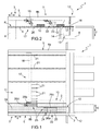
- Number 1 in Figures 1, 2 and 3 indicates as a whole a machine for cutting substantially parallelepiped-shaped, substantially rectangular-section panels 2 of wood or similar.
- Machine 1 comprises an elongated bed 3 extending in a horizontal direction 4 and having two parallel gantry structures 5, each of which extends in direction 4 and comprises two parallel uprights 6, which extend in a substantially vertical direction 7 crosswise to direction 4, and are connected at their top ends by a cross member 8 parallel to direction 4.
- Bed 3 is equipped with a known roller supporting device 9, which extends between the two structures 5, defines a substantially horizontal table P for at least one pack 10 of stacked panels 2, and cooperates with a feed device 11 for feeding the packs 10 of panels 2 in direction 4 and through a cutting station 12.
- Station 12 is equipped with a cutting assembly 13 comprising a carriage 14, which extends beneath table P, is connected in known manner to bed 3 to perform, with respect to bed 3 and under the control of a known actuating device not shown, straight back and forth movements in a horizontal direction 15 perpendicular to directions 4 and 7, and supports a blade 16 and a scoring device (not shown), which are fitted to carriage 14 to rotate about respective longitudinal axes (not shown) parallel to each other and to direction 4.
- a cutting assembly 13 comprising a carriage 14, which extends beneath table P, is connected in known manner to bed 3 to perform, with respect to bed 3 and under the control of a known actuating device not shown, straight back and forth movements in a horizontal direction 15 perpendicular to directions 4 and 7, and supports a blade 16 and a scoring device (not shown), which are fitted to carriage 14 to rotate about respective longitudinal axes (not shown) parallel to each other and to direction 4.
- Blade 16 and the scoring device are fitted in known manner to carriage 14 to perform, with respect to carriage 14, straight up and down movements in direction 7 between respective lowered rest positions, in which blade 16 and the scoring device (not shown) are located beneath table P so panels 2 can be fed along table P, and respective raised work positions, in which blade 16 and the scoring device (not shown) project above table P to cut a part (not shown) off each panel 2 in each pack 10.
- Blade 16 and the scoring device are also moved by carriage 14 in direction 15 and along a cutting plane perpendicular to direction 4, in a straight back and forth movement comprising a forward movement, in which the scoring device (not shown), located ahead of blade 16 in travelling direction 15 of carriage 14, scores the bottom panel 2 in each pack 10, and blade 16 cuts the panels 2 in packs 10, and a return movement.
- Device 11 comprises a first grip-and-carry assembly 17, in turn comprising a carriage 18, which extends in direction 15 between one of cross members 8 (hereinafter indicated 8a) and a portion of the other cross member 8 (hereinafter indicated 8b) projecting in direction 15 and defining a longitudinal guide member 19, is fitted in sliding manner to cross member 8a and to one end of member 19 to perform straight back and forth movements in direction 4 with respect to bed 3 and under the control of a known electric drive motor 20, and supports a number of (in the example shown, eight) grip-and-carry members 21 arranged along carriage 18 in direction 15.
- Each member 21 is a gripper comprising a top jaw and a bottom jaw movable with respect to each other between a grip position and a release position, and is movable with respect to carriage 18 between a lowered work position, in which member 21 extends between the rollers of supporting device 9, and a raised rest position, in which member 21 is located above table P, at a height greater than the maximum height of a pack 10 of panels 2.
- Device 11 also comprises a second grip-and-carry assembly 22, in turn comprising, in the example shown, a grip-and-carry member 23, which is identical to members 21, is mounted beneath member 19, and is fitted in sliding manner to member 19 to perform straight back and forth movements in direction 4 with respect to bed 3 and under the control of a known electric drive motor 24.
- a grip-and-carry assembly 22 comprising, in the example shown, a grip-and-carry member 23, which is identical to members 21, is mounted beneath member 19, and is fitted in sliding manner to member 19 to perform straight back and forth movements in direction 4 with respect to bed 3 and under the control of a known electric drive motor 24.
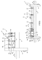
- Device 11 also comprises a third grip-and-carry assembly 25, in turn comprising a number of (in the example shown, four) grip-and-carry members 26, which are identical to members 21 and 23, are mounted beneath member 19, are fitted in sliding manner to member 19 to perform straight back and forth movements in direction 4 with respect to bed 3, and of which one (hereinafter indicated 26a) is positioned facing member 23, one (hereinafter indicated 26b) is positioned facing carriage 18, and the other two (hereinafter indicated 26c and 26d) are positioned between members 26a and 26b.
- a third grip-and-carry assembly 25 comprising a number of (in the example shown, four) grip-and-carry members 26, which are identical to members 21 and 23, are mounted beneath member 19, are fitted in sliding manner to member 19 to perform straight back and forth movements in direction 4 with respect to bed 3, and of which one (hereinafter indicated 26a) is positioned facing member 23, one (hereinafter indicated 26b) is positioned facing carriage 18, and the other two (hereinafter indicated 26c and 26d) are
- Members 26a, 26b, 26c, 26d are connected selectively to member 23 or carriage 18 by respective mechanical coupling devices 27, each of which comprises a first coupling member 28 and a second coupling member 29.
- Member 28 is defined by a pin extending in direction 15, is fitted to relative member 23, 26a, 26b, 26c, 26d, and is movable between an extracted lock position and a withdrawn release position; and member 29 is defined by a recess facing member 28, is fitted to the corresponding member 26a, 26b, 26c, 26d or carriage 18, and is designed to receive and retain member 28.
- members 26a, 26b, 26c, 26d of assembly 25 can be connected selectively to assembly 17 or 22, each of which therefore has a variable number of grip-and-carry members, depending on the size and/or shape of panels 2 and/or the cutting operations to be performed on panels 2, and is of variable width measured parallel to direction 15.
- members 26a and 26c are connected to each other and to member 23 by respective coupling devices 27, and are therefore moved in direction 4 by motor 24; and members 26b and 26d are connected to each other and to carriage 18 by respective coupling devices 27, and are therefore moved in direction 4 by motor 20.
- FIG. 4 variation differs from the Figure 1-3 embodiment by members 26b and 26d being replaced with a fourth grip-and-carry assembly 30 comprising, in the example shown, a grip-and-carry member 31, which is identical to members 21, 23 and 26, is mounted beneath member 19, and is fitted in sliding manner to member 19 to perform straight back and forth movements in direction 4 with respect to bed 3 and under the control of a known electric drive motor 32.
- a grip-and-carry member 31 which is identical to members 21, 23 and 26, is mounted beneath member 19, and is fitted in sliding manner to member 19 to perform straight back and forth movements in direction 4 with respect to bed 3 and under the control of a known electric drive motor 32.
- members 26a and 26c are connected to each other and to member 23 by respective coupling devices 27, and are therefore moved in direction 4 by motor 24; and member 31 is moved in direction 4 by motor 32.
- the Figure 5 variation differs from the Figure 4 variation by members 26a and 26c and coupling devices 27 being replaced with a fifth grip-and-carry assembly 33 comprising, in the example shown, a grip-and-carry member 34, which is identical to members 21, 23, 26 and 31, is mounted beneath member 19, and is fitted in sliding manner to member 19 to perform straight back and forth movements in direction 4 with respect to bed 3 and under the control of a known electric drive motor 35.
- a grip-and-carry member 34 which is identical to members 21, 23, 26 and 31, is mounted beneath member 19, and is fitted in sliding manner to member 19 to perform straight back and forth movements in direction 4 with respect to bed 3 and under the control of a known electric drive motor 35.
- motors 20, 24, 32, 35 are controlled selectively by an electronic central control unit (not shown) of machine 1, to move each assembly 17, 22, 30, 33 in direction 4 with a different law of motion from that of the other assemblies 17, 22, 30, 33, with the same law of motion as the other assemblies 17, 22, 30, 33, or with the same law of motion as some of the other assemblies 17, 22, 30, 33, and a different law of motion from that of the remaining assemblies 17, 22, 30, 33.
- members 21, 23, 31, 34 can therefore be connected electrically to one another into a single grip-and-carry assembly, or into a variable number of at most four independent grip-and-carry assemblies.
- each motor 32, 35 is selectively controlled to move relative assembly 30, 33 with the same law of motion as assembly 17 or 22.
Applications Claiming Priority (1)
| Application Number | Priority Date | Filing Date | Title |
|---|---|---|---|
| ITBO2009A000310A IT1394032B1 (it) | 2009-05-14 | 2009-05-14 | Macchina per il taglio di pannelli di legno o simili |
Publications (2)
| Publication Number | Publication Date |
|---|---|
| EP2251128A1 true EP2251128A1 (fr) | 2010-11-17 |
| EP2251128B1 EP2251128B1 (fr) | 2017-04-19 |
Family
ID=41413351
Family Applications (1)
| Application Number | Title | Priority Date | Filing Date |
|---|---|---|---|
| EP10162895.6A Active EP2251128B1 (fr) | 2009-05-14 | 2010-05-14 | Machine pour couper des plaques en bois ou similaires |
Country Status (5)
| Country | Link |
|---|---|
| EP (1) | EP2251128B1 (fr) |
| CN (1) | CN101885189B (fr) |
| BR (1) | BRPI1001632B1 (fr) |
| ES (1) | ES2627047T3 (fr) |
| IT (1) | IT1394032B1 (fr) |
Cited By (10)
| Publication number | Priority date | Publication date | Assignee | Title |
|---|---|---|---|---|
| EP2433732A1 (fr) | 2010-09-27 | 2012-03-28 | HOLZMA Plattenaufteiltechnik GmbH | Installation de distribution de plaques et son procédé de fonctionnement |
| ITBO20110399A1 (it) * | 2011-07-01 | 2013-01-02 | Biesse Spa | Macchina sezionatrice per il taglio di pannelli di legno o simili |
| ITTO20110759A1 (it) * | 2011-08-10 | 2013-02-11 | Biesse Spa | Macchina sezionatrice per il taglio di pannelli di legno o simili |
| ITBO20120268A1 (it) * | 2012-05-16 | 2013-11-17 | Biesse Spa | Macchina per la realizzazione di componenti di legno o simili |
| EP2732942A1 (fr) * | 2012-11-20 | 2014-05-21 | IMA Klessmann GmbH | Machine de découpe de portail et procédé de découpe de plaques grand format |
| EP2982467A1 (fr) * | 2014-08-07 | 2016-02-10 | BIESSE S.p.A. | Machine pour la coupe de panneaux de bois ou similaires |
| EP3081325B1 (fr) * | 2015-04-14 | 2018-12-12 | HOMAG Plattenaufteiltechnik GmbH | Installation de coupe de panneaux |
| DE102019100806A1 (de) | 2018-01-15 | 2019-07-18 | Valter Naldi | Plattensägemaschine |
| IT201800009460A1 (it) * | 2018-10-15 | 2020-04-15 | Biesse Spa | Macchina sezionatrice |
| IT202100010010A1 (it) * | 2021-04-20 | 2022-10-20 | Scm Group Spa | Metodo di posizionamento automatico di un pezzo nella stazione di ingresso di una macchina per la lavorazione di pezzi in legno e simili. |
Families Citing this family (2)
| Publication number | Priority date | Publication date | Assignee | Title |
|---|---|---|---|---|
| DE102014225073A1 (de) * | 2014-12-05 | 2016-06-09 | Holzma Plattenaufteiltechnik Gmbh | Plattenaufteilanlage zum Aufteilen von plattenförmigen Werkstücken, sowie Verfahren zu deren Betrieb |
| CN113829438B (zh) * | 2021-10-14 | 2022-10-14 | 浙江美典新材料有限公司 | 一种塑木地板加工工艺 |
Citations (6)
| Publication number | Priority date | Publication date | Assignee | Title |
|---|---|---|---|---|
| DE1080287B (de) * | 1958-12-10 | 1960-04-21 | Meyer & Schwabedissen F | Aufteilformatsaege fuer Platten |
| DE1821019U (de) * | 1958-12-10 | 1960-11-03 | Meyer & Schwabedissen F | Aufteilformatsaege fuer platten. |
| GB1285739A (en) * | 1968-11-21 | 1972-08-16 | Gino Benuzzi | Method and apparatus for cutting large boards into single panels |
| US3826164A (en) * | 1972-11-15 | 1974-07-30 | Wetoma Corp | Panel cutting method and apparatus |
| DE2614164A1 (de) * | 1975-04-07 | 1976-10-28 | Schelling & Co | Aufteilsaegeanlage insbesondere buntaufteilsaegemaschine |
| EP1510276A1 (fr) * | 2003-08-27 | 2005-03-02 | Valter Naldi | Machine à couper des panneaux |
Family Cites Families (12)
| Publication number | Priority date | Publication date | Assignee | Title |
|---|---|---|---|---|
| FR1548729A (fr) * | 1967-11-17 | 1968-12-06 | ||
| IT1056312B (it) * | 1975-12-23 | 1982-01-30 | Benuzzi G | Dispositivo per impostare automaticamente al taglio pacchidispositivo per impostare automaticamente al taglio pacchidi pannelli per derivare oannelli di ampiezza inferiure eda misure anche differenziate |
| AT362129B (de) * | 1978-08-16 | 1981-04-27 | Schelling & Co | Buntaufteilanlage fuer plattenartige werkstuecke |
| AT361698B (de) * | 1979-04-05 | 1981-03-25 | Schelling & Co | Plattenbesaeum- und aufteilsaege |
| AT361699B (de) * | 1979-06-11 | 1981-03-25 | Schelling & Co | Buntaufteilanlage fuer plattenartige werkstuecke |
| AT371045B (de) * | 1980-03-21 | 1983-05-25 | Schelling & Co | Einrichtung an auflagetischen fuer werkzeugmaschinen zum ausrichten von grossformatigen, streifen- oder plattenfoermigen werkstuecken |
| IT1298389B1 (it) * | 1997-12-24 | 2000-01-05 | Giben Impianti Spa | Macchina sezionatrice per il taglio di pannelli e relativo metodo di taglio. |
| ITBO20030645A1 (it) * | 2003-10-31 | 2005-05-01 | Giben Int Spa | Dispositivo per la rotazione di pannelli. |
| ITBO20050552A1 (it) * | 2005-09-09 | 2007-03-10 | Giben Int Spa | Macchina sezionatrice |
| DE102006013109B4 (de) * | 2006-03-22 | 2010-01-28 | Bernd Butzer | Werkzeugmaschine |
| ITBO20060673A1 (it) * | 2006-09-29 | 2008-03-30 | Giben Int Spa | Macchina sezionatrice di pannelli in legno od assimilabili. |
| DE102007010207B4 (de) * | 2007-03-02 | 2009-03-19 | Holzma Plattenaufteiltechnik Gmbh | Plattenaufteilanlage zum Aufteilen von plattenförmigen Werkstücken, sowie Verfahren zu deren Betrieb |
-
2009
- 2009-05-14 IT ITBO2009A000310A patent/IT1394032B1/it active
-
2010
- 2010-05-14 ES ES10162895.6T patent/ES2627047T3/es active Active
- 2010-05-14 BR BRPI1001632-5A patent/BRPI1001632B1/pt active IP Right Grant
- 2010-05-14 CN CN201010185679.8A patent/CN101885189B/zh active Active
- 2010-05-14 EP EP10162895.6A patent/EP2251128B1/fr active Active
Patent Citations (6)
| Publication number | Priority date | Publication date | Assignee | Title |
|---|---|---|---|---|
| DE1080287B (de) * | 1958-12-10 | 1960-04-21 | Meyer & Schwabedissen F | Aufteilformatsaege fuer Platten |
| DE1821019U (de) * | 1958-12-10 | 1960-11-03 | Meyer & Schwabedissen F | Aufteilformatsaege fuer platten. |
| GB1285739A (en) * | 1968-11-21 | 1972-08-16 | Gino Benuzzi | Method and apparatus for cutting large boards into single panels |
| US3826164A (en) * | 1972-11-15 | 1974-07-30 | Wetoma Corp | Panel cutting method and apparatus |
| DE2614164A1 (de) * | 1975-04-07 | 1976-10-28 | Schelling & Co | Aufteilsaegeanlage insbesondere buntaufteilsaegemaschine |
| EP1510276A1 (fr) * | 2003-08-27 | 2005-03-02 | Valter Naldi | Machine à couper des panneaux |
Cited By (12)
| Publication number | Priority date | Publication date | Assignee | Title |
|---|---|---|---|---|
| EP2433732A1 (fr) | 2010-09-27 | 2012-03-28 | HOLZMA Plattenaufteiltechnik GmbH | Installation de distribution de plaques et son procédé de fonctionnement |
| ITBO20110399A1 (it) * | 2011-07-01 | 2013-01-02 | Biesse Spa | Macchina sezionatrice per il taglio di pannelli di legno o simili |
| ITTO20110759A1 (it) * | 2011-08-10 | 2013-02-11 | Biesse Spa | Macchina sezionatrice per il taglio di pannelli di legno o simili |
| ITBO20120268A1 (it) * | 2012-05-16 | 2013-11-17 | Biesse Spa | Macchina per la realizzazione di componenti di legno o simili |
| EP2732942A1 (fr) * | 2012-11-20 | 2014-05-21 | IMA Klessmann GmbH | Machine de découpe de portail et procédé de découpe de plaques grand format |
| EP2982467A1 (fr) * | 2014-08-07 | 2016-02-10 | BIESSE S.p.A. | Machine pour la coupe de panneaux de bois ou similaires |
| EP3081325B1 (fr) * | 2015-04-14 | 2018-12-12 | HOMAG Plattenaufteiltechnik GmbH | Installation de coupe de panneaux |
| DE102019100806A1 (de) | 2018-01-15 | 2019-07-18 | Valter Naldi | Plattensägemaschine |
| IT201800009460A1 (it) * | 2018-10-15 | 2020-04-15 | Biesse Spa | Macchina sezionatrice |
| EP3639993A1 (fr) * | 2018-10-15 | 2020-04-22 | BIESSE S.p.A. | Machine à découper |
| IT202100010010A1 (it) * | 2021-04-20 | 2022-10-20 | Scm Group Spa | Metodo di posizionamento automatico di un pezzo nella stazione di ingresso di una macchina per la lavorazione di pezzi in legno e simili. |
| EP4079477A1 (fr) * | 2021-04-20 | 2022-10-26 | SCM Group S.p.A. | Procédé de positionnement automatique d'un panneau dans la station d'entrée d'une machine d'usinage de panneaux en bois et similaires |
Also Published As
| Publication number | Publication date |
|---|---|
| ITBO20090310A1 (it) | 2010-11-15 |
| CN101885189A (zh) | 2010-11-17 |
| BRPI1001632A2 (pt) | 2011-07-05 |
| ES2627047T3 (es) | 2017-07-26 |
| EP2251128B1 (fr) | 2017-04-19 |
| CN101885189B (zh) | 2015-01-21 |
| IT1394032B1 (it) | 2012-05-25 |
| BRPI1001632B1 (pt) | 2020-10-20 |
Similar Documents
| Publication | Publication Date | Title |
|---|---|---|
| EP2251128B1 (fr) | Machine pour couper des plaques en bois ou similaires | |
| EP2540429B1 (fr) | Machine de coupe pour panneaux de bois ou similaires | |
| EP2177482A1 (fr) | Procédé de découpe de feuilles de verre laminées | |
| EP2845840B1 (fr) | Machine et procédé pour effectuer des opérations de découpe sur des feuilles de verre laminées | |
| EP2574433B1 (fr) | Machine de coupe pour la coupe de panneaux en bois ou similaire | |
| US20160207221A1 (en) | Machine for cutting sheets, particularly of marble, granite, glass and composite materials | |
| EP3061582B1 (fr) | Machine pour découper des panneaux en bois ou similaire | |
| CN102935471A (zh) | 带有全自动板料上料装置的精冲机 | |
| JP2015516319A (ja) | 加工機械のための無停止ラック装置 | |
| CN108297142A (zh) | 一种自动上料的导光板切割装置 | |
| EP2801430B1 (fr) | Machine à découper des panneaux de bois ou analogue | |
| EP3012053B1 (fr) | Machine pour découper des panneaux en bois, en plastique ou similaire | |
| CN103171923A (zh) | 堆叠设备 | |
| EP2233236B1 (fr) | Procédé et machine pour couper des panneaux en bois ou similaires | |
| CN212191733U (zh) | 一种具有液压升降交换工作台的激光切割机 | |
| CN203888511U (zh) | 切割与雕刻一体机 | |
| CN102935470A (zh) | 精冲机全自动板坯上料装置 | |
| CN203401350U (zh) | 板材自动裁边机 | |
| EP2982467A1 (fr) | Machine pour la coupe de panneaux de bois ou similaires | |
| CN203739316U (zh) | 一种纸板分板机构 | |
| KR101142523B1 (ko) | 목재 가공장치 | |
| CN210389453U (zh) | 一种三向剪头垫切断装置 | |
| CN201471534U (zh) | 电动冲切床 | |
| EP3696123B1 (fr) | Dispositif d'alimentation d'un produit en feuille | |
| KR20150049102A (ko) | 절단 겸용 가공장치 |
Legal Events
| Date | Code | Title | Description |
|---|---|---|---|
| PUAI | Public reference made under article 153(3) epc to a published international application that has entered the european phase |
Free format text: ORIGINAL CODE: 0009012 |
|
| AK | Designated contracting states |
Kind code of ref document: A1 Designated state(s): AL AT BE BG CH CY CZ DE DK EE ES FI FR GB GR HR HU IE IS IT LI LT LU LV MC MK MT NL NO PL PT RO SE SI SK SM TR |
|
| AX | Request for extension of the european patent |
Extension state: BA ME RS |
|
| 17P | Request for examination filed |
Effective date: 20110517 |
|
| GRAP | Despatch of communication of intention to grant a patent |
Free format text: ORIGINAL CODE: EPIDOSNIGR1 |
|
| INTG | Intention to grant announced |
Effective date: 20161111 |
|
| GRAS | Grant fee paid |
Free format text: ORIGINAL CODE: EPIDOSNIGR3 |
|
| GRAA | (expected) grant |
Free format text: ORIGINAL CODE: 0009210 |
|
| AK | Designated contracting states |
Kind code of ref document: B1 Designated state(s): AL AT BE BG CH CY CZ DE DK EE ES FI FR GB GR HR HU IE IS IT LI LT LU LV MC MK MT NL NO PL PT RO SE SI SK SM TR |
|
| REG | Reference to a national code |
Ref country code: GB Ref legal event code: FG4D |
|
| REG | Reference to a national code |
Ref country code: CH Ref legal event code: EP |
|
| REG | Reference to a national code |
Ref country code: AT Ref legal event code: REF Ref document number: 885477 Country of ref document: AT Kind code of ref document: T Effective date: 20170515 |
|
| REG | Reference to a national code |
Ref country code: IE Ref legal event code: FG4D |
|
| REG | Reference to a national code |
Ref country code: DE Ref legal event code: R096 Ref document number: 602010041601 Country of ref document: DE |
|
| REG | Reference to a national code |
Ref country code: ES Ref legal event code: FG2A Ref document number: 2627047 Country of ref document: ES Kind code of ref document: T3 Effective date: 20170726 |
|
| REG | Reference to a national code |
Ref country code: NL Ref legal event code: MP Effective date: 20170419 |
|
| REG | Reference to a national code |
Ref country code: LT Ref legal event code: MG4D |
|
| PG25 | Lapsed in a contracting state [announced via postgrant information from national office to epo] |
Ref country code: NL Free format text: LAPSE BECAUSE OF FAILURE TO SUBMIT A TRANSLATION OF THE DESCRIPTION OR TO PAY THE FEE WITHIN THE PRESCRIBED TIME-LIMIT Effective date: 20170419 |
|
| PG25 | Lapsed in a contracting state [announced via postgrant information from national office to epo] |
Ref country code: FI Free format text: LAPSE BECAUSE OF FAILURE TO SUBMIT A TRANSLATION OF THE DESCRIPTION OR TO PAY THE FEE WITHIN THE PRESCRIBED TIME-LIMIT Effective date: 20170419 Ref country code: LT Free format text: LAPSE BECAUSE OF FAILURE TO SUBMIT A TRANSLATION OF THE DESCRIPTION OR TO PAY THE FEE WITHIN THE PRESCRIBED TIME-LIMIT Effective date: 20170419 Ref country code: HR Free format text: LAPSE BECAUSE OF FAILURE TO SUBMIT A TRANSLATION OF THE DESCRIPTION OR TO PAY THE FEE WITHIN THE PRESCRIBED TIME-LIMIT Effective date: 20170419 Ref country code: GR Free format text: LAPSE BECAUSE OF FAILURE TO SUBMIT A TRANSLATION OF THE DESCRIPTION OR TO PAY THE FEE WITHIN THE PRESCRIBED TIME-LIMIT Effective date: 20170720 Ref country code: NO Free format text: LAPSE BECAUSE OF FAILURE TO SUBMIT A TRANSLATION OF THE DESCRIPTION OR TO PAY THE FEE WITHIN THE PRESCRIBED TIME-LIMIT Effective date: 20170719 |
|
| PG25 | Lapsed in a contracting state [announced via postgrant information from national office to epo] |
Ref country code: SE Free format text: LAPSE BECAUSE OF FAILURE TO SUBMIT A TRANSLATION OF THE DESCRIPTION OR TO PAY THE FEE WITHIN THE PRESCRIBED TIME-LIMIT Effective date: 20170419 Ref country code: PL Free format text: LAPSE BECAUSE OF FAILURE TO SUBMIT A TRANSLATION OF THE DESCRIPTION OR TO PAY THE FEE WITHIN THE PRESCRIBED TIME-LIMIT Effective date: 20170419 Ref country code: BG Free format text: LAPSE BECAUSE OF FAILURE TO SUBMIT A TRANSLATION OF THE DESCRIPTION OR TO PAY THE FEE WITHIN THE PRESCRIBED TIME-LIMIT Effective date: 20170719 Ref country code: IS Free format text: LAPSE BECAUSE OF FAILURE TO SUBMIT A TRANSLATION OF THE DESCRIPTION OR TO PAY THE FEE WITHIN THE PRESCRIBED TIME-LIMIT Effective date: 20170819 Ref country code: LV Free format text: LAPSE BECAUSE OF FAILURE TO SUBMIT A TRANSLATION OF THE DESCRIPTION OR TO PAY THE FEE WITHIN THE PRESCRIBED TIME-LIMIT Effective date: 20170419 |
|
| REG | Reference to a national code |
Ref country code: CH Ref legal event code: PL |
|
| REG | Reference to a national code |
Ref country code: DE Ref legal event code: R097 Ref document number: 602010041601 Country of ref document: DE |
|
| PG25 | Lapsed in a contracting state [announced via postgrant information from national office to epo] |
Ref country code: EE Free format text: LAPSE BECAUSE OF FAILURE TO SUBMIT A TRANSLATION OF THE DESCRIPTION OR TO PAY THE FEE WITHIN THE PRESCRIBED TIME-LIMIT Effective date: 20170419 Ref country code: CZ Free format text: LAPSE BECAUSE OF FAILURE TO SUBMIT A TRANSLATION OF THE DESCRIPTION OR TO PAY THE FEE WITHIN THE PRESCRIBED TIME-LIMIT Effective date: 20170419 Ref country code: MC Free format text: LAPSE BECAUSE OF FAILURE TO SUBMIT A TRANSLATION OF THE DESCRIPTION OR TO PAY THE FEE WITHIN THE PRESCRIBED TIME-LIMIT Effective date: 20170419 Ref country code: RO Free format text: LAPSE BECAUSE OF FAILURE TO SUBMIT A TRANSLATION OF THE DESCRIPTION OR TO PAY THE FEE WITHIN THE PRESCRIBED TIME-LIMIT Effective date: 20170419 Ref country code: SK Free format text: LAPSE BECAUSE OF FAILURE TO SUBMIT A TRANSLATION OF THE DESCRIPTION OR TO PAY THE FEE WITHIN THE PRESCRIBED TIME-LIMIT Effective date: 20170419 Ref country code: DK Free format text: LAPSE BECAUSE OF FAILURE TO SUBMIT A TRANSLATION OF THE DESCRIPTION OR TO PAY THE FEE WITHIN THE PRESCRIBED TIME-LIMIT Effective date: 20170419 |
|
| REG | Reference to a national code |
Ref country code: IE Ref legal event code: MM4A |
|
| PLBE | No opposition filed within time limit |
Free format text: ORIGINAL CODE: 0009261 |
|
| STAA | Information on the status of an ep patent application or granted ep patent |
Free format text: STATUS: NO OPPOSITION FILED WITHIN TIME LIMIT |
|
| PG25 | Lapsed in a contracting state [announced via postgrant information from national office to epo] |
Ref country code: CH Free format text: LAPSE BECAUSE OF NON-PAYMENT OF DUE FEES Effective date: 20170531 Ref country code: LI Free format text: LAPSE BECAUSE OF NON-PAYMENT OF DUE FEES Effective date: 20170531 Ref country code: SM Free format text: LAPSE BECAUSE OF FAILURE TO SUBMIT A TRANSLATION OF THE DESCRIPTION OR TO PAY THE FEE WITHIN THE PRESCRIBED TIME-LIMIT Effective date: 20170419 |
|
| REG | Reference to a national code |
Ref country code: FR Ref legal event code: ST Effective date: 20180131 |
|
| 26N | No opposition filed |
Effective date: 20180122 |
|
| GBPC | Gb: european patent ceased through non-payment of renewal fee |
Effective date: 20170719 |
|
| PG25 | Lapsed in a contracting state [announced via postgrant information from national office to epo] |
Ref country code: LU Free format text: LAPSE BECAUSE OF NON-PAYMENT OF DUE FEES Effective date: 20170514 |
|
| REG | Reference to a national code |
Ref country code: BE Ref legal event code: MM Effective date: 20170531 |
|
| PG25 | Lapsed in a contracting state [announced via postgrant information from national office to epo] |
Ref country code: IE Free format text: LAPSE BECAUSE OF NON-PAYMENT OF DUE FEES Effective date: 20170514 Ref country code: GB Free format text: LAPSE BECAUSE OF NON-PAYMENT OF DUE FEES Effective date: 20170719 |
|
| PG25 | Lapsed in a contracting state [announced via postgrant information from national office to epo] |
Ref country code: FR Free format text: LAPSE BECAUSE OF NON-PAYMENT OF DUE FEES Effective date: 20170619 Ref country code: SI Free format text: LAPSE BECAUSE OF FAILURE TO SUBMIT A TRANSLATION OF THE DESCRIPTION OR TO PAY THE FEE WITHIN THE PRESCRIBED TIME-LIMIT Effective date: 20170419 |
|
| PG25 | Lapsed in a contracting state [announced via postgrant information from national office to epo] |
Ref country code: BE Free format text: LAPSE BECAUSE OF NON-PAYMENT OF DUE FEES Effective date: 20170531 |
|
| PG25 | Lapsed in a contracting state [announced via postgrant information from national office to epo] |
Ref country code: MT Free format text: LAPSE BECAUSE OF NON-PAYMENT OF DUE FEES Effective date: 20170514 |
|
| PG25 | Lapsed in a contracting state [announced via postgrant information from national office to epo] |
Ref country code: HU Free format text: LAPSE BECAUSE OF FAILURE TO SUBMIT A TRANSLATION OF THE DESCRIPTION OR TO PAY THE FEE WITHIN THE PRESCRIBED TIME-LIMIT; INVALID AB INITIO Effective date: 20100514 |
|
| PG25 | Lapsed in a contracting state [announced via postgrant information from national office to epo] |
Ref country code: CY Free format text: LAPSE BECAUSE OF NON-PAYMENT OF DUE FEES Effective date: 20170419 |
|
| REG | Reference to a national code |
Ref country code: AT Ref legal event code: UEP Ref document number: 885477 Country of ref document: AT Kind code of ref document: T Effective date: 20170419 |
|
| PG25 | Lapsed in a contracting state [announced via postgrant information from national office to epo] |
Ref country code: MK Free format text: LAPSE BECAUSE OF FAILURE TO SUBMIT A TRANSLATION OF THE DESCRIPTION OR TO PAY THE FEE WITHIN THE PRESCRIBED TIME-LIMIT Effective date: 20170419 |
|
| PG25 | Lapsed in a contracting state [announced via postgrant information from national office to epo] |
Ref country code: TR Free format text: LAPSE BECAUSE OF FAILURE TO SUBMIT A TRANSLATION OF THE DESCRIPTION OR TO PAY THE FEE WITHIN THE PRESCRIBED TIME-LIMIT Effective date: 20170419 |
|
| PG25 | Lapsed in a contracting state [announced via postgrant information from national office to epo] |
Ref country code: PT Free format text: LAPSE BECAUSE OF FAILURE TO SUBMIT A TRANSLATION OF THE DESCRIPTION OR TO PAY THE FEE WITHIN THE PRESCRIBED TIME-LIMIT Effective date: 20170419 |
|
| PG25 | Lapsed in a contracting state [announced via postgrant information from national office to epo] |
Ref country code: AL Free format text: LAPSE BECAUSE OF FAILURE TO SUBMIT A TRANSLATION OF THE DESCRIPTION OR TO PAY THE FEE WITHIN THE PRESCRIBED TIME-LIMIT Effective date: 20170419 |
|
| PGFP | Annual fee paid to national office [announced via postgrant information from national office to epo] |
Ref country code: IT Payment date: 20230502 Year of fee payment: 14 Ref country code: ES Payment date: 20230613 Year of fee payment: 14 Ref country code: DE Payment date: 20230530 Year of fee payment: 14 |
|
| PGFP | Annual fee paid to national office [announced via postgrant information from national office to epo] |
Ref country code: AT Payment date: 20230519 Year of fee payment: 14 |