EP2249740B1 - Zahnimplantat und verfahren zu seiner herstellung - Google Patents
Zahnimplantat und verfahren zu seiner herstellung Download PDFInfo
- Publication number
- EP2249740B1 EP2249740B1 EP09714335A EP09714335A EP2249740B1 EP 2249740 B1 EP2249740 B1 EP 2249740B1 EP 09714335 A EP09714335 A EP 09714335A EP 09714335 A EP09714335 A EP 09714335A EP 2249740 B1 EP2249740 B1 EP 2249740B1
- Authority
- EP
- European Patent Office
- Prior art keywords
- base
- neck
- dental implant
- implant according
- abutment
- Prior art date
- Legal status (The legal status is an assumption and is not a legal conclusion. Google has not performed a legal analysis and makes no representation as to the accuracy of the status listed.)
- Not-in-force
Links
- 238000004519 manufacturing process Methods 0.000 title claims description 5
- 239000007943 implant Substances 0.000 title description 30
- 239000004053 dental implant Substances 0.000 claims description 27
- 238000005530 etching Methods 0.000 claims description 15
- KWYUFKZDYYNOTN-UHFFFAOYSA-M Potassium hydroxide Chemical compound [OH-].[K+] KWYUFKZDYYNOTN-UHFFFAOYSA-M 0.000 claims description 12
- 238000000034 method Methods 0.000 claims description 10
- 238000005422 blasting Methods 0.000 claims description 7
- 229910001069 Ti alloy Inorganic materials 0.000 claims description 5
- RTAQQCXQSZGOHL-UHFFFAOYSA-N Titanium Chemical compound [Ti] RTAQQCXQSZGOHL-UHFFFAOYSA-N 0.000 claims description 5
- 229910052719 titanium Inorganic materials 0.000 claims description 5
- 239000010936 titanium Substances 0.000 claims description 5
- 239000003795 chemical substances by application Substances 0.000 claims description 4
- 229910052751 metal Inorganic materials 0.000 claims description 2
- 239000002184 metal Substances 0.000 claims description 2
- 229910001092 metal group alloy Inorganic materials 0.000 claims description 2
- RVTZCBVAJQQJTK-UHFFFAOYSA-N oxygen(2-);zirconium(4+) Chemical compound [O-2].[O-2].[Zr+4] RVTZCBVAJQQJTK-UHFFFAOYSA-N 0.000 claims description 2
- 229910001928 zirconium oxide Inorganic materials 0.000 claims description 2
- 210000001519 tissue Anatomy 0.000 description 22
- 210000000988 bone and bone Anatomy 0.000 description 16
- 238000003780 insertion Methods 0.000 description 12
- 230000037431 insertion Effects 0.000 description 12
- 230000012010 growth Effects 0.000 description 11
- 230000003993 interaction Effects 0.000 description 10
- 230000003746 surface roughness Effects 0.000 description 9
- 238000003801 milling Methods 0.000 description 8
- 238000013461 design Methods 0.000 description 7
- 210000002919 epithelial cell Anatomy 0.000 description 7
- 239000000463 material Substances 0.000 description 7
- 241000894006 Bacteria Species 0.000 description 6
- 241000245772 Gasteria Species 0.000 description 6
- 238000010276 construction Methods 0.000 description 6
- 238000005259 measurement Methods 0.000 description 6
- 210000004027 cell Anatomy 0.000 description 4
- 238000009826 distribution Methods 0.000 description 4
- 210000000963 osteoblast Anatomy 0.000 description 4
- 230000007704 transition Effects 0.000 description 4
- HEMHJVSKTPXQMS-UHFFFAOYSA-M Sodium hydroxide Chemical compound [OH-].[Na+] HEMHJVSKTPXQMS-UHFFFAOYSA-M 0.000 description 3
- 229910052593 corundum Inorganic materials 0.000 description 3
- 239000010431 corundum Substances 0.000 description 3
- 238000011161 development Methods 0.000 description 3
- 230000000694 effects Effects 0.000 description 3
- 210000002950 fibroblast Anatomy 0.000 description 3
- NJPPVKZQTLUDBO-UHFFFAOYSA-N novaluron Chemical compound C1=C(Cl)C(OC(F)(F)C(OC(F)(F)F)F)=CC=C1NC(=O)NC(=O)C1=C(F)C=CC=C1F NJPPVKZQTLUDBO-UHFFFAOYSA-N 0.000 description 3
- 238000010079 rubber tapping Methods 0.000 description 3
- 238000013519 translation Methods 0.000 description 3
- 230000006978 adaptation Effects 0.000 description 2
- 230000015572 biosynthetic process Effects 0.000 description 2
- 210000002449 bone cell Anatomy 0.000 description 2
- 230000010261 cell growth Effects 0.000 description 2
- 210000002808 connective tissue Anatomy 0.000 description 2
- 239000004744 fabric Substances 0.000 description 2
- 239000011521 glass Substances 0.000 description 2
- 239000004576 sand Substances 0.000 description 2
- 239000002253 acid Substances 0.000 description 1
- 230000002730 additional effect Effects 0.000 description 1
- 239000000853 adhesive Substances 0.000 description 1
- 230000001070 adhesive effect Effects 0.000 description 1
- 238000013459 approach Methods 0.000 description 1
- 230000008952 bacterial invasion Effects 0.000 description 1
- 239000011324 bead Substances 0.000 description 1
- 239000012620 biological material Substances 0.000 description 1
- 239000008280 blood Substances 0.000 description 1
- 210000004369 blood Anatomy 0.000 description 1
- 238000012512 characterization method Methods 0.000 description 1
- 230000001886 ciliary effect Effects 0.000 description 1
- 239000000470 constituent Substances 0.000 description 1
- 230000008094 contradictory effect Effects 0.000 description 1
- 238000005520 cutting process Methods 0.000 description 1
- 230000007423 decrease Effects 0.000 description 1
- 230000001419 dependent effect Effects 0.000 description 1
- 238000005516 engineering process Methods 0.000 description 1
- 210000000981 epithelium Anatomy 0.000 description 1
- 230000002349 favourable effect Effects 0.000 description 1
- 238000000338 in vitro Methods 0.000 description 1
- 238000011534 incubation Methods 0.000 description 1
- 230000002401 inhibitory effect Effects 0.000 description 1
- 238000009434 installation Methods 0.000 description 1
- 238000005457 optimization Methods 0.000 description 1
- 230000002188 osteogenic effect Effects 0.000 description 1
- 239000002245 particle Substances 0.000 description 1
- 230000035515 penetration Effects 0.000 description 1
- 230000008092 positive effect Effects 0.000 description 1
- 210000000332 tooth crown Anatomy 0.000 description 1
- 238000003466 welding Methods 0.000 description 1
- 238000009736 wetting Methods 0.000 description 1
- 230000029663 wound healing Effects 0.000 description 1
Images


Classifications
-
- A—HUMAN NECESSITIES
- A61—MEDICAL OR VETERINARY SCIENCE; HYGIENE
- A61C—DENTISTRY; APPARATUS OR METHODS FOR ORAL OR DENTAL HYGIENE
- A61C8/00—Means to be fixed to the jaw-bone for consolidating natural teeth or for fixing dental prostheses thereon; Dental implants; Implanting tools
- A61C8/0018—Means to be fixed to the jaw-bone for consolidating natural teeth or for fixing dental prostheses thereon; Dental implants; Implanting tools characterised by the shape
- A61C8/0022—Self-screwing
-
- A—HUMAN NECESSITIES
- A61—MEDICAL OR VETERINARY SCIENCE; HYGIENE
- A61C—DENTISTRY; APPARATUS OR METHODS FOR ORAL OR DENTAL HYGIENE
- A61C8/00—Means to be fixed to the jaw-bone for consolidating natural teeth or for fixing dental prostheses thereon; Dental implants; Implanting tools
- A61C8/0048—Connecting the upper structure to the implant, e.g. bridging bars
- A61C8/005—Connecting devices for joining an upper structure with an implant member, e.g. spacers
- A61C8/0066—Connecting devices for joining an upper structure with an implant member, e.g. spacers with positioning means
-
- A—HUMAN NECESSITIES
- A61—MEDICAL OR VETERINARY SCIENCE; HYGIENE
- A61C—DENTISTRY; APPARATUS OR METHODS FOR ORAL OR DENTAL HYGIENE
- A61C8/00—Means to be fixed to the jaw-bone for consolidating natural teeth or for fixing dental prostheses thereon; Dental implants; Implanting tools
- A61C8/0048—Connecting the upper structure to the implant, e.g. bridging bars
- A61C8/0077—Connecting the upper structure to the implant, e.g. bridging bars with shape following the gingival surface or the bone surface
-
- A—HUMAN NECESSITIES
- A61—MEDICAL OR VETERINARY SCIENCE; HYGIENE
- A61C—DENTISTRY; APPARATUS OR METHODS FOR ORAL OR DENTAL HYGIENE
- A61C8/00—Means to be fixed to the jaw-bone for consolidating natural teeth or for fixing dental prostheses thereon; Dental implants; Implanting tools
- A61C8/0018—Means to be fixed to the jaw-bone for consolidating natural teeth or for fixing dental prostheses thereon; Dental implants; Implanting tools characterised by the shape
- A61C8/0037—Details of the shape
- A61C2008/0046—Textured surface, e.g. roughness, microstructure
-
- A—HUMAN NECESSITIES
- A61—MEDICAL OR VETERINARY SCIENCE; HYGIENE
- A61C—DENTISTRY; APPARATUS OR METHODS FOR ORAL OR DENTAL HYGIENE
- A61C8/00—Means to be fixed to the jaw-bone for consolidating natural teeth or for fixing dental prostheses thereon; Dental implants; Implanting tools
- A61C8/0048—Connecting the upper structure to the implant, e.g. bridging bars
- A61C8/005—Connecting devices for joining an upper structure with an implant member, e.g. spacers
- A61C8/006—Connecting devices for joining an upper structure with an implant member, e.g. spacers with polygonal positional means, e.g. hexagonal or octagonal
-
- A—HUMAN NECESSITIES
- A61—MEDICAL OR VETERINARY SCIENCE; HYGIENE
- A61C—DENTISTRY; APPARATUS OR METHODS FOR ORAL OR DENTAL HYGIENE
- A61C8/00—Means to be fixed to the jaw-bone for consolidating natural teeth or for fixing dental prostheses thereon; Dental implants; Implanting tools
- A61C8/0048—Connecting the upper structure to the implant, e.g. bridging bars
- A61C8/005—Connecting devices for joining an upper structure with an implant member, e.g. spacers
- A61C8/0069—Connecting devices for joining an upper structure with an implant member, e.g. spacers tapered or conical connection
- A61C8/0072—Connecting devices for joining an upper structure with an implant member, e.g. spacers tapered or conical connection including male and female conical parts with different angles
Definitions
- the invention relates to a dental implant, comprising a base insertable into a jawbone bone with an apical body and a coronal neck whose outer surfaces each have a surface microstructure of predetermined roughness, the mean surface roughness value being greater than the value of mean roughness of the neck surface.
- the invention further relates to a method for producing a dental implant socket.
- Such dental implants are known from the DE 60 2004 007 427 T2 (German translation of the EP 1 477 141 B1 ).
- the dental implant always comprises a base, which is at least partially inserted into the jawbone.
- the pedestal is subdivided into two axial regions.
- a first area, called a body, is essentially completely inserted into the jawbone in its intended end position.
- a coronal adjoining second region, called the neck protrudes in the intended end position substantially completely beyond the jawbone and is surrounded by gum tissue.
- Coronal of the socket typically employs a structure that extends substantially completely beyond the gum tissue.
- the structure serves as the core of a crown to be attached to it.
- the structure may be formed integrally with the base or as a separate component, which is screwed or glued to the base, for example.
- the outer surface of the body is often provided with a possibly self-tapping thread with which the base is screwed into a predrilled recess in the jawbone.
- a permanent fixation of the implant depends substantially on the interaction between the biological material, ie bone and / or gum tissue, beyond the prefixing with the base surface.
- the biocompatibility of the base material is important.
- bases made of titanium or titanium alloys have proven themselves.
- the surface structure of the base is of considerable importance. In this regard, a variety of studies have been and are being carried out, sometimes with contradictory results. There is agreement that microstructuring of the surface can have positive effects.
- the DE 695 33 448 T2 (German translation of the EP 0 794 745 B1 ) suggests the formation of a uniform surface roughness for the body and neck of the implant socket.
- the generic DE 60 2004 007 427 T2 On the other hand, it takes into account the different tissue properties of bone material and gingival tissue and thus suggests a different surface roughness for the body area and the neck area of the base. In particular, it is proposed to set the surface roughness of the body to one to three micrometers by an etching method, whereas the surface of the neck is to be made "relatively smooth".
- the proposed roughness values according to the invention are the result of a complex, experimentally verified balance between the optimization of each surface for the interaction with the respectively associated tissue type on the one hand and the compatibility of the surface with the other tissue type on the other hand.
- this sub-optimal design of each surface area with respect to the respectively associated tissue overall leads to an improved durability of the implant, since the resulting, significantly improved Interaction in the critical transition region between bone and gums overcompensating effect. It seems that in the case of implants according to the state of the art, the incompatibilities of the surfaces optimized for one type of tissue with the respective other type of tissue have hitherto underestimated negative influences on the overall durability of the implant. In any case, no such reports are known.
- the invention is the result of a hitherto nowhere pursued, more holistic approach.
- the roughness values according to the invention can be achieved in any desired manner.
- it has proven to be efficient to render the surface microstructure of the body surface hard by blasting Blasting agent, such as sand or corundum, and a subsequent etching process and to produce the surface microstructure of the neck surface by an etching process.
- the etching is preferably carried out with a basic etchant, in particular an etchant containing a high concentration of potassium hydroxide.
- a basic etchant in particular an etchant containing a high concentration of potassium hydroxide.
- Such an etching method is known from DE 603 01 796 T2 (German translation of the EP 1 515 759 B1 ), which, however, deals with the multilayer structure of a dental implant socket.
- the base preferably consists essentially of metal or a metal alloy, in particular of titanium or a titanium alloy.
- the body preferably carries a macroscopic external thread structure.
- This can, as known from the prior art, screw into a prefabricated recess in the jawbone and represents a positive mechanical fixation of the base, which allows an increase of the tissue on the inventively designed base surface.
- Favorable here are self-tapping threaded structures.
- the neck has a circumferential annular groove.
- the annular groove advantageously carries a circular segment-shaped cross section with a radius of 0.2 to 0.3 millimeters, in particular of about 2.5 millimeters.
- Such an annular groove improves the growth of desired tissue on the Base surface.
- a common problem in the growth are namely fast-growing epithelial cells, which grow along the base surface from coronal to apical and thus hinder or prevent the onset of gums on the neck of the base or very extensive epithelial cell growth and the growth of bone cells on the body surface.
- the slower growing gum cells gain sufficient time to grow in the neck before the epithelial cells overgrow these areas. There is no longer any danger of the apical areas being overgrown by the epithelial cells, so that the even slower growing bone cells have sufficient time to grow in the body area of the base.
- An additional effect of the advantageous annular groove is the enlargement of the interaction surface compared to a substantially cylindrical base neck. This increases the overall force with which the implant is held in the tissue.
- the connective tissue which has grown into the annular groove constitutes a seal in the manner of an O-ring, which offers good protection against the penetration of undesired dirt particles. It should be noted that the formation of the annular groove is not necessarily coupled to the surface roughness distribution according to the invention. Rather, it is also possible to significantly improve implants with other roughness distributions of their base surface by the illustrated annular groove.
- the pedestal is substantially hollow and has an insertion area for a corresponding connection area of the structure.
- the connection between the body and socket often takes place through a screw passing through the structure and screwed into an internal thread of the socket. This inevitably results in permanent cavities in the base interior. It is of particular importance that these cavities are sealed gas and bacteria impermeable.
- a critical zone is the contact zone between the receiving opening of the base and the insertion of the structure.
- a structure which is used with a conical connection region in a receiving area of the hollow internally formed base, wherein the conical connection region with a conical taper angle conical having an apical tapered outer surface, the receiving area in the coronal area of the neck has a tapered to a socket opening angle to the inner surface tapered and the cone angle is 20 to 60 minutes of arc greater than the base opening angle.
- the absolute amount of the socket opening angle and the construction cone angle is preferably 15 degrees to 25 degrees, preferably about 20 degrees.
- the build-up cone angle is therefore slightly blunter than the socket opening angle.
- titanium, titanium alloys and zirconium oxide As an essential material for the structure, titanium, titanium alloys and zirconium oxide have been proven.
- a major problem with two-piece dental implants is the achievement of an anti-rotation of the structure relative to the base on the one hand and precise alignment of the structure relative to the base on the other.
- the structure has apical of the conical connection region a non-rotationally symmetrical Vermosterrorismvorsprung, which is positively inserted into a corresponding Vermosterrorismausappelung the base.
- the Vernstoffvorsprung and the corresponding Vermosstoffausappelung preferably have axially aligned walls.
- the anti-rotation projection and the corresponding anti-rotation recess are formed several times in a multi-axis or multiple rotation-inversion-symmetrical manner.
- the former case occurs, for example, in uniform, even-numbered polygon or star shapes
- the second case for example, in uniform, odd-numbered polygon or star shapes as a profile of the Vercardvorsprungs and the Verfterrorismaus Principleung on.
- Verreschschsch are basically from the DE 600 022 35 T2 known.
- a high-order symmetry should be realized. Preference is given to 12-fold veiled, star or cloverleaf shapes.
- the alignment of the structure and base to each other plays no or only a minor role.
- a coronal structure adjoining the neck is included, which is connected in one piece with the base.
- the cohesive connection can be done for example by a cementitious adhesive or welding.
- optimum tightness against gas and bacteria is ensured.
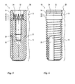
- FIGS. 1 to 4 show various representations of a preferred embodiment of an implant base according to the invention 10.
- the base 10 comprises an apically located body 12 and a coronal thereto adjoining neck 14.
- the body 12 is substantially surrounded by bone tissue, while the neck 14 is substantially surrounded by gingival tissue.
- the base body 12 is divided into two sections, namely a coronal, substantially cylindrical portion 16 and an apically thereto, conically in and radius expiring portion 18.
- Both sections 16, 18, carry a Hereins, macroscopic external thread whose depth decreases toward the apex of the cone in the conical section 18 and runs to zero.
- the thread serves to mechanically pre-fix the base in a recess drilled prior to insertion into the jawbone.
- the thread is preferably self-tapping, so that screwing into a bone recess with straight borehole walls is possible.
- the embodiment shown carries an axially extending and a right angle with a radial direction engaging milling edge 20, the depth of which corresponds approximately to the thread depth.
- the milling edge 20 extends over the entire threaded portion of the conical portion 18 and protrudes coronal beyond this slightly into the cylindrical portion 16 out.
- Such a milling edge 20, which does not carry the macroscopic thread structure, has proven to be an advantageous interaction surface with the bone tissue and improves the growth behavior, so that a firmer ingrowth of the base 10 is achieved in the jawbone.
- two such Fräskanten 20 which face each other point-symmetrical to the center of the cross-sectional plane of the base.
- milling edges 20 may be provided.
- the rectangular configuration of the milling edges 20 is not absolutely necessary, although advantageous in terms of manufacturing technology.
- the angled configuration of the milling edge 20 has in comparison to a basically also possible milling edge along a continuous chord (relative to the cross section) the advantage of a more efficient protection against rotational and radial translational forces acting on the ingrown base 10.
- the neck 14 of the illustrated embodiment of the implant base 10 is substantially cylindrical in its apical region and has an annular groove 22 interrupting the cylindrical surface.
- the annular groove 22 adjacent cylindrical portions 24 of the neck 14 in about the same width, which in turn corresponds to the width of the annular groove 22 approximately.
- the neck 14 in the ingrown state is substantially surrounded by gingival tissue.
- the gingival tissue also grows the annular groove 22 and forms an effective seal in the manner of an O-ring.
- edges of the annular groove 22 act at the junctions to the cylindrical regions 24 growth inhibiting epithelial cells, which can typically grow very quickly from coronal to apical along the outer wall of the base 10 and the growth of slower growing gum tissue cells in the neck 14th and possibly obstruct bone tissue cells in the region of the body 12.
- this carries a chamfer 26, with which the coronal end of the neck 14 is tapered. This achieves a better contour adaptation to a fitting on the base structure, the below in connection with FIG. 7 will be described in more detail.
- the base 10 is substantially hollow, as in particular from the sectional view of FIG. 1 is apparent.
- the apical region of the inner recess of the base 10 is formed as a blind bore 28 with an internal thread 30.
- This internal thread 30 is used in connection with below FIG. 7 to be described sterfix réelle the structure.
- Coronal to the blind bore 28 is followed by a receiving area 32 for the construction, wherein the receiving area 32 is divided into two sections.
- a coronal section 34 which serves as an insertion area for the structure, is formed substantially in the shape of an apical hollow cone, while the apical section 36, which serves as anti-twist protection for the structure, has a straight wall which carries projections extending the hollow conical surface.
- the resulting non-rotationally symmetric structure is well recognizable, which in the embodiment shown is in the form of a 12-beam star.
- This structure serves as related below FIG. 7 is explained in more detail, the rotation of the structure.
- the receiving area 32 is also at its narrowest point, ie its apical boundary, wider than the adjacent blind hole 28, so that a shoulder 38 is formed.
- the shoulder 38 serves as a stop surface for the structure to be described below.
- the in the Figures 1 and 2 recognizable macroscopic surface structure of the base 10 is superimposed on a not recognizable in the figures and in principle independent of the macroscopic structure advantageously usable microstructure.
- This microstructure can be characterized in particular according to its roughness values.
- the so-called RA value according to DIN EN ISO 4287 which corresponds to the arithmetic mean roughness, can be used in particular.
- AFM atomic force microscope
- the body 12 of the base 10 is coated with a hard abrasive such as sand, glass beads or corundum of appropriate size until an RA value is reached the ultimately desired RA value is blasted.
- the entire base 10 is subjected to a basic etching treatment with a basic etchant containing a high concentration of potassium hydroxide and basically from the DE 603 01 796 T2 is known, subject.
- the etching is carried out until the neck 14 and body 12 of the base 10 have reached the desired roughness values of their surfaces.
- a machined implant neck and corundum blasted body are treated with 1 mol / l NaOH + 2% H 2 O 2 at 80 ° C for 10 minutes followed by acid etching at 98 ° C for 1 hour.
- the difference in roughness between the neck and body allows selective growth of fibroblasts in the neck area and osteoblasts in the body area.
- the neck surface also has good osteogenic properties, so that in the area of the bone / gingival transition even at non-straight bone level, good growth of the osteoblasts can occur. This one is smooth Neck surfaces not possible.
- the thus reduced adhesion of desired cell types can lead to an increased growth rate of epithelial cells, which then form a long ciliary epithelium along the neck to the junction between the neck and the body. This area is then sensitive to bacterial invasion (perimplantitis). Preventing the epithelial deep growth by a tight connective tissue cuff in the neck area, which is made possible by the inventive design of the surfaces of the neck and body, prevents bone perforations.
- FIGS. 5 and 6 represent different views of a second embodiment of a base 10 according to the invention.
- the total body 12 is substantially cylindrical and carries a continuous thread.
- the reference numerals in the FIGS. 5 and 6 were taken over.
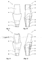
- the assembly 40 includes a substantially hollow cylindrical coronal portion 42, an apically adjoining support portion 44, an apically adjoining connecting portion 46, and an anti-rotation protrusion 48 forming the apical end of the assembly 40 Through hole 50 passes through, which has a larger diameter in its coronal area than in its apical region, so that a shoulder 52 is formed.
- the conically apically tapered connecting portion 46 is designed corresponding to the conical lead-in portion 34 of the receiving space 32 of the base 10.
- the anti-rotation projection 48 is designed corresponding to the apical anti-rotation area 36 of the receiving space 32 of the base 10.
- the shoulder 38 in the base 10 forms a stop surface for the apical end surface of the anti-rotation projection 48.
- the structure 40 can be rotatably inserted into the base 10, wherein the conical insertion portion 34 of the receiving space 32 of the base 10 serves as a centering aid.
- a fixing screw 54 can be inserted into the through-bore 50 and bolted to the internal thread 30 in the base 10. The head 56 of the screw 54, whose diameter projects beyond the screw shaft, finds an abutment on the shoulder 52.
- the conical connection region 46 of the structure 40 is adapted to the conical insertion region 34 of the receiving space 32 of the base 10. It is not absolutely necessary that the construction cone angle of conical connecting portion 46 of the structure 40 exactly corresponds to the opening angle of the conical insertion portion 34 of the receiving space 32 of the base 10. Rather, it is preferably provided that the construction cone angle is 20-60 minutes of arc greater than the base opening angle, so that at the coronal edge of the base 10, a contact line on which a large pressure acts arises. This contact line forms a reliable gas and bacteria seal. It should be noted that in this case the structure 40 with its apical end face is not allowed to abut against the shoulder 38 of the base 10. In this case, it is also advantageous if the non-rotationally symmetrical projections in the anti-rotation region 36 of the receiving space 32 of the base 10 have exactly axially aligned walls in order to ensure a high axial tolerance.
- the support portion 44 of the assembly 40 serves to support a crown, not shown in the figures, which is attached to the structure 40.
- the support region is preferably formed double concave.
- FIG. 8 shows an embodiment in which the structure 40 is integrally connected to the base. Special measures for anti-rotation are not required in this case.
- FIGS. 9 and 10 show two views of another embodiment of a structure, wherein the coronal, the base 10 in the assembled state superior area has a more complex, adapted to a specific tooth geometry structure.
- FIGS. 11 and 12 show a further embodiment of an advantageous construction 40, the embodiment of the FIGS. 9 and 10 is similar, but in the case of an angle between the tooth crown and the artificial root that forms the implant base, is provided.
- FIG. 13 shows an integral embodiment of an implant in which the base 10 and the structure 40 are designed as a common component.
- FIG. 14 schematically shows the structure of a natural row of teeth with roots 60 and crowns 62, wherein the bone boundary 64 and the gingival boundary 66 are shown. Note the interdental papillae 68 projecting high into the interdental space in healthy teeth.
- FIG. 15 schematically shows a row of teeth with an implant according to the prior art. One recognizes the frequent problem that in the spaces between the adjacent teeth of the implant, the interdental papillae 68 are degenerated due to the onset of difficulty.
- FIG. 16 schematically shows a row of teeth with an implant according to the invention. Note that due to the improved accretion, the interdental papillae 68 are formed as with natural teeth.
Landscapes
- Health & Medical Sciences (AREA)
- Oral & Maxillofacial Surgery (AREA)
- Orthopedic Medicine & Surgery (AREA)
- Dentistry (AREA)
- Epidemiology (AREA)
- Life Sciences & Earth Sciences (AREA)
- Animal Behavior & Ethology (AREA)
- General Health & Medical Sciences (AREA)
- Public Health (AREA)
- Veterinary Medicine (AREA)
- Dental Prosthetics (AREA)
Description
- Die Erfindung bezieht sich auf ein Zahnimplantat, umfassend einen bereichsweise in einen Kieferknochen inserierbaren Sockel mit einem apikal gelegenen Körper und einem koronal gelegenen Hals, deren äußere Oberflächen jeweils eine Oberflächen-Mikrostruktur vorgegebener Rauheit aufweisen, wobei der Wert der mittleren Rauheit der Körperoberfläche größer ist als der Wert der mittleren Rauheit der Halsoberfläche.
- Die Erfindung betrifft weiter ein Verfahren zur Herstellung eines Zahnimplantatsockels.
- Derartige Zahnimplantate sind bekannt aus der
DE 60 2004 007 427 T2 (deutsche Übersetzung derEP 1 477 141 B1 ). - Enossale Zahnimplantate sind seit langem bekannt, wobei sich im Laufe der Entwicklung die unterschiedlichsten Varianten und unterschiedliche, zu ihrer Beschreibung verwendete Terminologien herausgebildet haben. Im Rahmen der hiesigen Anmeldung wird sowohl bei der Beschreibung des Standes der Technik als auch bei der Erläuterung der Erfindung von folgender Terminologie ausgegangen: das Zahnimplantat umfasst stets einen Sockel, der wenigstens bereichsweise in den Kieferknochen inseriert wird. Bei den von der vorliegenden Erfindung betroffenen Zahnimplantaten ist der Sockel in zwei axiale Bereiche unterteilbar. Ein erster Bereich, Körper genannt, ist in bestimmungsgemäßer Endlage im Wesentlichen vollständig in den Kieferknochen inseriert. Ein sich koronal anschließender zweiter Bereich, Hals genannt, ragt in bestimmungsgemäßer Endlage im Wesentlichen vollständig über den Kieferknochen hinaus und ist von Zahnfleischgewebe umgeben. Koronal des Sockels setzt typischerweise ein Aufbau an, der im Wesentlichen vollständig über das Zahnfleischgewebe hinausragt. Der Aufbau dient als Kern einer an ihm zu befestigenden Krone. Der Aufbau kann einstückig mit dem Sockel oder als separates Bauteil ausgebildet sein, welches mit dem Sockel beispielsweise verschraubt oder verklebt wird.
- Zur mechanischen Vorfixierung des Sockels im Kieferknochen ist die Außenfläche des Körpers oft mit einem ggf. selbstschneidenden Gewinde versehen, mit dem der Sockel in eine vorgebohrte Ausnehmung im Kieferknochen eingeschraubt wird. Eine dauerhafte Fixierung des Implantats hängt jedoch wesentlich von der über diese Vorfixierung hinausgehenden Wechselwirkung zwischen dem biologischen Material, d.h. Knochen- und/oder Zahnfleischgewebe, mit der Sockeloberfläche ab. Wichtig ist zunächst die Biokompatibilität des Sockelmaterials. Hier haben sich Sockel aus Titan oder Titanlegierungen bewährt. Für die optimale Wechselwirkung zwischen Gewebe und Sockelmaterial ist jedoch auch die Oberflächenstruktur des Sockels von erheblicher Bedeutung. Diesbezüglich wurden und werden vielfältige Studien mit zum Teil einander widersprechenden Ergebnissen durchgeführt. Einigkeit besteht darüber, dass eine Mikrostrukturierung der Oberfläche positive Effekte zeitigen kann.
- Die
DE 695 33 448 T2 (deutsche Übersetzung derEP 0 794 745 B1 ) schlägt die Ausbildung einer gleichmäßigen Oberflächenrauheit für Körper und Hals des Implantatsockels vor. Die gattungsbildendeDE 60 2004 007 427 T2 berücksichtigt hingegen die unterschiedlichen Gewebeeigenschaften von Knochenmaterial und Zahnfleischgewebe und schlägt folglich eine unterschiedliche Oberflächenrauheit für den Körperbereich und den Halsbereich des Sockels vor. Insbesondere wird vorgeschlagen, die Oberflächenrauheit des Körpers durch ein Ätzverfahren auf ein bis drei Mikrometer einzustellen, wohingegen die Oberfläche des Halses "relativ glatt" auszubilden ist. Dies führt zu einer scharfen Trennkante der Oberflächenrauheiten von Körper und Hals, wobei die Rauheit der Körperoberfläche für die Wechselwirkung mit dem Knochengewebe und die Oberflächenrauheit des Halses für die Wechselwirkung mit dem Zahnfleischgewebe optimiert sein soll. Nachteilig bei diesen bekannten Implantaten ist, dass im inserierten Zustand die Rauheitsgrenze in der Regel nicht oder wenigstens nicht vollumfänglich mit der Gewebegrenze zwischen Knochen und Zahnfleisch übereinstimmt. Dies liegt weniger an einem unpräzisen Einsetzen des Implantats als vielmehr an der natürlichen Form des Knochenkamms im Kiefer, die typischerweise nicht die Einbringung einer Ausnehmung mit perfekt horizontalem Rand, der der Rauheitsgrenze entsprechen würde, erlaubt. Folglich ergeben sich Zwischenbereiche, in denen ein Gewebematerial mit einer Oberfläche wechselwirken muss, die eine für diese Wechselwirkung völlig ungeeignete Oberflächenrauheit aufweist.US 2006/246397 A1 offenbart ein Zahnimplantat, dessen Halsoberfläche "mikro-aufgeraut" ist, und, dessen Körperdoberfläche "aufgeraut" ist. - Es ist die Aufgabe der vorliegenden Erfindung, gattungsgemäße Zahnimplantate derart weiterzubilden, dass insbesondere im Übergangsbereich zwischen Knochen- und Zahnfleischgewebe eine verbesserte Anwachsung erfolgt.
- Diese Aufgabe wird in Verbindung mit den Merkmalen des Oberbegriffs von Anspruch 1 dadurch gelöst, dass der Wert der mittleren Rauheit der Körperoberfläche Ra=0,75 bis 0,95 Mikrometer und der Wert der mittleren Rauheit der Halsoberfläche Ra=0,55 bis 0,71 Mikrometer beträgt.
- Die vorgeschlagenen, erfindungsgemäßen Rauheitswerte sind das Ergebnis einer aufwendigen, experimentell überprüften Abwägung zwischen der Optimierung jeder Oberfläche für die Wechselwirkung mit der ihr jeweils zugeordneten Gewebeart einerseits und der Kompatibilität der Oberfläche mit der jeweils anderen Gewebeart andererseits. Überraschenderweise führt diese suboptimale Ausgestaltung jedes Oberflächenbereichs im Hinblick auf das jeweils zugeordnete Gewebe insgesamt zu einer verbesserten Haltbarkeit des Implantats, da die resultierende, deutlich verbesserte Wechselwirkung im kritischen Übergangsbereich zwischen Knochen und Zahnfleisch überkompensierend wirkt. Es hat den Anschein als hätten bei Implantaten nach dem Stand der Technik die Unverträglichkeiten der für jeweils eine Gewebeart optimierten Oberflächen mit der jeweils anderen Gewebeart bislang völlig unterschätzte negative Einflüsse auf die Gesamthaltbarkeit des Implantats. Entsprechende Berichte sind jedenfalls nicht bekannt. Die Erfindung ist das Ergebnis eines bisher nirgends verfolgten, ganzheitlicheren Ansatzes.
- Als weiterer Vorteil der Erfindung ergibt sich eine gesteigerte Variabilität beim Einsetzen des erfindungsgemäßen Implantats. Durch die erläuterte verbesserte Verträglichkeit der Oberflächenbeschaffenheiten der verschiedenen Bereiche mit der jeweils anderen Gewebeart ist es möglich, beim Einsetzvorgang die Einsatztiefe bedarfsweise zu variieren ohne die Haltbarkeit des Implantats zu gefährden. Bei Implantaten nach dem Stand der Technik müsste hingegen im Fall, dass unter der Operation eine andere als die beabsichtigte Einsatztiefe erforderlich wird, ein anderes, entsprechend dimensioniertes Implantat verwendet werden. Eine Variation der Einsetztiefe eines gegebenen Implantats wäre nicht möglich.
- Besonders vorteilhafte Ausführungsformen der Erfindung sind Gegenstand der abhängigen Ansprüche.
- Grundsätzlich können die erfindungsgemäßen Rauheitswerte auf beliebige Weise erzielt werden. Es hat sich jedoch als effizient erwiesen, die Oberflächen-Mikrostruktur der Körperoberfläche durch einen Strahlvorgang mit einem harten Strahlmittel, beispielsweise Sand oder Korund, und einem nachfolgenden Ätzvorgang und die Oberflächen-Mikrostruktur der Halsoberfläche durch einen Ätzvorgang zu erzeugen. Der Ätzvorgang erfolgt vorzugsweise mit einem basischen Ätzmittel, insbesondere ein Ätzmittel, dass eine hohe Konzentration von Kaliumhydroxid enthält. Ein derartiges Ätzverfahren ist aus der
DE 603 01 796 T2 (deutsche Übersetzung derEP 1 515 759 B1 ) bekannt, die sich im Übrigen jedoch mit dem mehrschichtigen Aufbau eines Zahnimplantatsockels beschäftigt. - Aufgrund der erwiesenen Biokompatibilität besteht der Sockel vorzugsweise im Wesentlichen aus Metall oder einer Metalllegierung, insbesondere aus Titan oder eine Titanlegierung.
- Um eine rein mechanische Vorfixierung im Kieferknochen zu erreichen, trägt der Körper vorzugsweise eine makroskopische Außengewindestruktur. Diese lässt sich, wie aus dem Stand der Technik bekannt, in eine vorgefertigte Ausnehmung im Kieferknochen eindrehen und stellt eine formschlüssige mechanische Fixierung des Sockels dar, die ein Anwachsen des Gewebes an der erfindungsgemäß gestalteten Sockeloberfläche erlaubt. Günstig sind hierbei selbstschneidende Gewindestrukturen.
- Bevorzugt weist der Hals eine umlaufende Ringnut auf. Die Ringnut trägt günstigerweise einen kreisabschnittförmigen Querschnitt mit einem Radius von 0,2 bis 0,3 Millimetern, insbesondere von etwa 2,5 Millimetern. Eine solche Ringnut verbessert die Anwachsung erwünschten Gewebes an der Sockeloberfläche. Ein häufiges Problem bei der Anwachsung sind nämlich schnell wachsende Epithelzellen, die von koronal nach apikal an der Sockeloberfläche entlangwachsen und damit die Anwachsung von Zahnfleisch am Hals des Sockels bzw. bei sehr weitgehendem Epithelzellwuchs auch die Anwachsung der Knochenzellen an der Körperoberfläche behindern oder verhindern. Es hat sich jedoch herausgestellt, dass scharfe Kanten, wie sie beispielsweise die Nutränder einer Ringnut mit bevorzugt etwa halbkreisförmigen Querschnitt aufweisen, das unerwünschte Epithelzellwachstum behindern. Somit gewinnen die langsamer wachsenden Zahnfleisch- bzw. Bindegewebszellen ausreichend Zeit, um im Halsbereich anzuwachsen, bevor die Epithelzellen diese Bereich überwachsen. Damit besteht auch keine Gefahr mehr, dass weiter apikal liegende Bereiche von den Epithelzellen überwachsen werden, sodass die noch langsamer wachsenden Knochenzellen ausreichend Zeit haben, um im Körperbereich des Sockels anzuwachsen. Ein zusätzlicher Effekt der vorteilhaften Ringnut ist die Vergrößerung der Wechselwirkungsoberfläche im Vergleich zu einem im Wesentlichen zylinderförmigen Sockelhals. Hierdurch wird die Gesamtkraft, mit der das Implantat im Gewebe gehalten wird, vergrößert. Schließlich stellt das in die Ringnut eingewachsene Bindegewebe eine Dichtung nach Art eines O-Rings dar, der einen guten Schutz vor dem Eindringen von unerwünschten Schmutzpartikeln bietet. Man beachte, dass die Ausbildung der Ringnut nicht zwingend an die erfindungsgemäße Oberflächenrauheitsverteilung gekoppelt ist. Vielmehr ist es möglich, auch Implantate mit anderen Rauheitsverteilungen ihrer Sockeloberfläche durch die erläuterte Ringnut wesentlich zu verbessern.
- Eine wichtige Problemzone von Zahnimplantaten ist der Übergang vom Sockel zum Aufbau. Typischerweise ist der Sockel im Wesentlichen hohl gestaltet und weist einen Einführbereich für einen korrespondierenden Verbindungsbereich des Aufbaus auf. Die Verbindung zwischen Aufbau und Sockel erfolgt häufig durch eine den Aufbau durchsetzende und in ein Innengewinde des Sockels eingeschraubte Schraube. Hierdurch ergeben sich zwangsläufig bleibende Hohlräume im Sockelinneren. Es ist von besonderer Wichtigkeit, dass diese Hohlräume gas- und bakteriendicht abgeschlossen werden. Eine kritische Zone ist dabei die Kontaktzone zwischen der Aufnahmeöffnung des Sockels und dem Einführbereich des Aufbaus. Zur Verbesserung der Gas- und Bakteriendichtigkeit ist daher bei einer Weiterbildung der Erfindung vorgesehen, dass ein Aufbau umfasst ist, der mit einem konischen Verbindungsbereich in einen Aufnahmebereich des innen hohl ausgebildeten Sockels einsetzbar ist, wobei der konische Verbindungsbereich eine mit einem Aufbau-Kegelwinkel konisch nach apikal zulaufende Außenfläche aufweist, der Aufnahmebereich im koronalen Bereich des Halses eine mit einem Sockel-Öffnungswinkel konisch nach apikal zulaufende Innenfläche aufweist und der Aufbau-Kegelwinkel 20 bis 60 Bogenminuten größer ist als der Sockel-Öffnungswinkel. Der Absolutbetrag des Sockel-Öffnungswinkels bzw. des Aufbau-Kegelwinkels liegt bevorzugt bei 15 Grad bis 25 Grad, vorzugsweise bei ca. 20 Grad. Der Aufbau-Kegelwinkel ist daher geringfügig stumpfer als der Sockel-Öffnungswinkel. Dies führt zu einer scharfen, ringförmigen Kontaktzone zwischen dem konischen Verbindungsbereich des Aufbaus und der Aufnahmeöffnung des Sockels. Bei einer Verschraubung beider Elemente wirkt aufgrund der geringen Fläche der Kontaktzonen ein hoher Druck, der eine sehr gute Gas- und Bakteriendichtigkeit erzeugt. Man beachte, dass diese Art der dichten Verbindung eine Umkehrung des so genannten Glasschliffdeckel-Prinzips darstellt, bei dem der Kegelwinkel eines einzuführenden Stopfens geringfügig spitzer ist als der Öffnungswinkel der korrespondierenden Aufnahme, wobei die Verschlusswirkung bei dieser Konstruktion auf der besonders großen Fläche der Wechselwirkungszone beruht. Man beachte, dass die erläuterte, vorteilhafte Dichtung zwischen Sockel und Aufbau nicht zwingend mit der erfindungsgemäßen Verteilung der Oberflächenrauheiten des Sockels gekoppelt sein muss. Vielmehr ist sie durchaus geeignet, auch mehrteilige Zahnimplantate mit anderer Sockeloberflächen-Gestaltung im Hinblick auf die Gas- und Bakteriendichtigkeit zu verbessern.
- Als wesentliches Material für den Aufbau haben sich Titan, Titanlegierungen und Zirkon-Oxyd bewährt. Ein wesentliches Problem bei zweiteiligen Zahnimplantaten ist die Erzielung einer Verdrehsicherung des Aufbaus gegenüber dem Sockel einerseits und eine präzise Ausrichtbarkeit des Aufbaus relativ zum Sockel andererseits.
- Bei einer vorteilhaften Weiterbildung der Erfindung ist daher vorgesehen, dass der Aufbau apikal des konischen Verbindungsbereichs einen nicht-rotationssymmetrischen Verdrehschutzvorsprung aufweist, der formschlüssig in eine korrespondierende Verdrehschutzausnehmung des Sockels einführbar ist. Der Verdrehschutzvorsprung und die korrespondierende Verdrehschutzausnehmung weisen bevorzugt axial ausgerichtete Wandungen auf. Durch die fehlende Rotationssymmetrie ist bei formschlüssigen Eingreifen des Vorsprungs in die Ausnehmung der Verdrehschutz gegeben. Um eine gute Ausrichtbarkeit zu erreichen, kann zusätzlich vorgesehen sein, dass der Verdrehschutzvorsprung und die korrespondierende Verdrehschutzausnehmung mehrfach Achsen- oder mehrfach rotations-inversions-symmetrisch ausgebildet sind. Der erstgenannte Fall tritt beispielsweise bei gleichmäßigen, geradzahligen Vieleck- oder Sternformen auf, während der zweite Fall beispielsweise bei gleichmäßigen, ungeradzahligen Vieleck- oder Sternformen als Profil des Verdrehvorsprungs und der Verdrehschutzausnehmung auf. Derartige Verdrehschutzmaßnahmen sind im Grunde aus der
DE 600 022 35 T2 bekannt. Um die Ausrichtbarkeit zu verbessern, sollte eine Symmetrie hoher Ordnung verwirklicht werden. Bevorzugt werden 12-facheVieleck-, Stern oder Kleeblattformen. - In manchen Fällen spielt jedoch die Ausrichtung von Aufbau und Sockel zueinander keine oder nur eine untergeordnete Rolle. In diesen Fällen kann vorgesehen sein, dass ein sich koronal an den Hals anschließender Aufbau umfasst ist, der mit dem Sockel einstückig verbunden ist. Die stoffschlüssige Verbindung kann beispielsweise durch einen zementartigen Klebstoff oder Verschweißen erfolgen. Bei diesen Varianten, insbesondere der einstückigen Ausbildung, ist eine optimale Dichtigkeit gegen Gas und Bakterien gewährleistet.
- Auch stoffschlüssige Verbindungen von Aufbau und Sockel sind realisierbar, wobei der Stoffschluss fallweise vor oder nach dem Einsetzen des Sockels vorgenommen werden kann.
- Weitere Merkmale und Vorteile der Erfindung ergeben sich aus der nachfolgenden, speziellen Beschreibung und den Zeichnungen.
- Es zeigen:
- Figur 1:
- eine Schnittdarstellung einer ersten Ausführungsform eines erfindungsgemäßen Zahnimplantatsockels
- Figur 2:
- eine Seitenansicht des Sockels von
Figur 1 - Figur 3:
- eine Draufsicht auf den Sockel von
Figur 1 - Figur 4:
- eine Unteransicht des Sockels von
Figur 2 - Figur 5:
- eine Schnittdarstellung einer zweiten Ausführungsform eines erfindungsgemäßen Zahnimplantatsockels
- Figur 6:
- eine Seitenansicht des Sockels von
Figur 5 - Figur 7:
- eine Schnittdarstellung des Sockels von
Figur 1 mit einer ersten Ausführungsform eines eingesetzten Aufbaus - Figur 8:
- eine Schnittdarstellung eines Sockels mit stoffschlüssig verbundener, zweiter Ausführungsform eines Aufbaus.
- Figur 9:
- eine Seitenansicht einer dritten Ausführungsform eines Aufbaus
- Figur 10:
- eine teilweise geschnittene und ausgebrochene Seitenansicht des Sockels von
Figur 9 - Figur 11:
- eine Seitenansicht einer vierten Ausführungsform eines Aufbaus
- Figur 12:
- eine teilweise geschnittene und ausgebrochene Darstellung des Aufbaus von
Figur 11 - Figur 13:
- eine einteilige Ausführungsform eines erfindungsgemäßen Implantates
- Figur 14:
- eine schematische Darstellung einer natürlichen Zahnreihe
- Figur 15:
- eine schematische Darstellung einer Zahnreihe mit einem Implantat gemäß dem Stand der Technik
- Figur 16:
- eine schematische Darstellung einer Zahnreihe mit einem erfindungsgemäßen Implantat.
- Die
Figuren 1 bis 4 zeigen verschiedene Darstellungen einer bevorzugten Ausführungsform eines erfindungsgemäßen Implantatsockels 10. Der Sockel 10 umfasst einen apikal gelegenen Körper 12 und einen sich koronal daran anschließenden Hals 14. Im implantierten Zustand (vgl.Figur 16 ) ist der Körper 12 im Wesentlichen von Knochengewebe umgeben, während der Hals 14 im Wesentlichen von Zahnfleischgewebe umwachsen ist. Bei der bevorzugten Ausführungsform ist der Sockelkörper 12 in zwei Abschnitte unterteilt, nämlich einen koronal gelegenen, im Wesentlichen zylindrischen Abschnitt 16 und einen apikal hierzu gelegenen, konisch zu- und in einem Radius auslaufenden Abschnitt 18. Beide Abschnitte 16, 18, tragen ein mehrgängiges, makroskopisches Außengewinde, dessen Tiefe sich in Richtung auf die Kegelspitze im konischen Abschnitt 18 verringert und gegen Null ausläuft. Das Gewinde dient der mechanischen Vorfixierung des Sockels in einer vor dem Einsetzen in den Kieferknochen gebohrten Ausnehmung. Das Gewinde ist vorzugsweise selbstschneidend ausgebildet, sodass ein Eindrehen in eine Knochenausnehmung mit geraden Bohrlochwänden möglich ist. - Die gezeigte Ausführungsform trägt eine sich axial erstreckende und einen rechten Winkel mit einer Radialrichtung einnehmende Fräskante 20, deren Frästiefe in etwa der Gewindetiefe entspricht. Die Fräskante 20 erstreckt sich über den gesamten, gewindetragenden Bereich des konischen Abschnitts 18 und ragt koronal über diesen geringfügig in den zylindrischen Abschnitt 16 hinaus. Eine derartige Fräskante 20, die nicht die makroskopische Gewindestruktur trägt, hat sich als vorteilhafte Wechselwirkungsfläche mit dem Knochengewebe ergeben und verbessert das Anwachsverhalten, sodass eine festere Einwachsung des Sockels 10 in den Kieferknochen erreicht wird. Zur Steigerung dieses Effektes weist die dargestellte Ausführungsform zwei derartige Fräskanten 20 auf, die einander punktsymmetrisch zum Mittelpunkt der Querschnittsebene des Sockels gegenüberliegen. Bei anderen, nicht dargestellten Ausführungsformen können mehr oder weniger als zwei Fräskanten 20 vorgesehen sein. Auch die rechtwinklige Ausbildung der Fräskanten 20 ist nicht zwingend erforderlich, wenngleich fertigungstechnisch vorteilhaft. Die winklige Ausgestaltung der Fräskante 20 hat im Vergleich zu einer grundsätzlich ebenfalls möglichen Fräskante entlang einer durchgehenden Kreissehne (bezogen auf den Querschnitt) den Vorteil einer effizienteren Sicherung gegen Rotations- und radiale Translationskräfte, die auf den eingewachsenen Sockel 10 wirken.
- Der Hals 14 der dargestellten Ausführungsform des Implantatsockels 10 ist in seinem apikalen Bereich im Wesentlichen zylindrisch ausgebildet und weist eine die Zylinderfläche unterbrechende Ringnut 22 auf. Bei der dargestellten Ausführungsform weisen die der Ringnut 22 benachbarten, zylindrischen Bereiche 24 des Halses 14 in etwa die gleiche Breite auf, die ihrerseits der Breite der Ringnut 22 in etwa entspricht. Wie erwähnt, ist der Hals 14 im eingewachsenen Zustand im Wesentlichen von Zahnfleischgewebe umgeben. Das Zahnfleischgewebe wächst insbesondere auch die Ringnut 22 ein und bildet eine wirksame Dichtung nach Art eines O-Rings. Außerdem wirken die Kanten der Ringnut 22 an den Übergängen zu den zylindrischen Bereichen 24 wachstumshemmend auf Epithelzellen, die typischerweise sehr schnell von koronal nach apikal an der Außenwand des Sockels 10 entlang wachsen können und die Anwachsung von langsamer wachsenden Zahnfleischgewebezellen im Bereich des Halses 14 und ggf. Knochengewebezellen im Bereich des Körpers 12 behindern können.
- Im koronalen Endbereich des Halses 14 trägt dieser eine Anfasung 26, mit der der koronale Abschluss des Halses 14 verjüngt wird. Hierdurch gelingt eine bessere Konturanpassung an einen auf dem Sockel aufsetzenden Aufbau, der weiter unten in Verbindung mit
Figur 7 näher beschrieben werden soll. - In seinem Inneren ist der Sockel 10 im Wesentlichen hohl ausgebildet, wie insbesondere aus der Schnittdarstellung von
Figur 1 ersichtlich ist. Der apikale Bereich der inneren Ausnehmung des Sockels 10 ist als Sackbohrung 28 mit einem Innengewinde 30 ausgebildet. Dieses Innengewinde 30 dient der weiter unten in Zusammenhang mitFigur 7 zu beschreibenden Schraubfixierung des Aufbaus. Koronal an die Sackbohrung 28 schließt sich ein Aufnahmebereich 32 für den Aufbau an, wobei der Aufnahmebereich 32 in zwei Abschnitte unterteilt ist. Ein koronaler Abschnitt 34, der als Einführbereich für den Aufbau dient, ist im Wesentlichen nach apikal hohlkegelförmig zulaufend ausgebildet, während der apikal gelegene Abschnitt 36, der als Verdrehschutz für den Aufbau dient, eine gerade Wandung aufweist, die die Hohlkegelfläche fortsetzende Vorsprünge trägt. In der Draufsicht derFigur 3 ist die resultierende nicht-rotationssymmetrische Struktur gut erkennbar, die bei der gezeigten Ausführungsform die Form eines 12-strahligen Sterns aufweist. Diese Struktur dient, wie weiter unten in Zusammenhang mitFigur 7 näher erläutert wird, der Verdrehsicherung des Aufbaus. Der Aufnahmebereich 32 ist auch an seiner engsten Stelle, d.h. seiner apikalen Grenze, breiter ausgebildet als die benachbarte Sackbohrung 28, sodass sich eine Schulter 38 bildet. Die Schulter 38 dient als Anschlagfläche für den weiter unten zu beschreibenden Aufbau. - Der in den
Figuren 1 und 2 erkennbaren makroskopischen Oberflächenstruktur des Sockels 10 ist eine in den Figuren nicht erkennbare und grundsätzlich auch unabhängig von der makroskopischen Struktur vorteilhaft einsetzbare Mikrostruktur überlagert. Diese Mikrostruktur lässt sich insbesondere gemäß ihren Rauheitswerten charakterisieren. Zur Charakterisierung kann insbesondere der so genannte RA-Wert gemäß DIN EN ISO 4287 dienen, der dem arithmetischen Mittenrauwert entspricht. Bei einer besonders bevorzugten Ausführungsform beträgt der RA-Wert, gemessen im Rahmen einer Linienmessung über 2000 Mikrometer im Bereich des Halses 14 RA=0,68 ± 0,02 Mikrometer und im Bereich des Körpers RA 0,90 ± 0,03 Mikrometer. Gemessen über eine Strecke von 800 Mikrometern ergaben sich bei demselben Implantatsockel im Bereich des Halses RA=0,61 ± 0,03 Mikrometer und im Bereich des Körpers RA=0,79 ± 0,03 Mikrometer. Eine Flächenmessung mittels eines AFM (atomic force microscope) über 100 x 100 Mikrometer ergab am selben Messobjekt einen SA-Wert im Bereich des Halses von SA=0,451 ± 0,023 Mikrometer und im Bereich des Körpers SA=0,598 ± 0,031 Mikrometer. - Zur Herstellung derartiger Rauheitswerte wird, ausgehend von einer geschliffenen oder polierten, die gewünschte Makrostruktur tragenden Oberfläche, der Körper 12 des Sockels 10 mit einem harten Strahlmittel, wie beispielsweise Sand, Glasperlen oder Korund geeigneter Größe bis zur Erzielung eines RA-Wertes, der größer als der letztendlich gewünschte RA-Wert ist, gestrahlt. Dieser temporäre Rauheitswert kann insbesondere eine Größenordnung von RA=0,85 bis 1,20 Mikrometer annehmen. Im Fall des bereits weiter oben beschriebenen Beispiels lag der temporäre RA-Wert bei einer Linienmessung über 2000 Mikrometer bei RA=1,13 ± 0,04 Mikrometer und bei einer Linienmessung über 800 Mikrometer bei RA=0,89 ± 0,02 Mikrometer. Der entsprechende SA-Wert einer Flächenmessung über 100 x 100 Mikrometer betrug SA=0,705 ± 0,033 Mikrometer. In einem nachfolgenden Verfahrensschritt wird der gesamte Sockel 10 einer basischen Ätz-Behandlung mit einem basischen Ätzmittel, das eine hohe Konzentration von Kaliumhydroxid enthält und grundsätzlich aus der
DE 603 01 796 T2 bekannt ist, unterworfen. Das Ätzen wird solange durchgeführt, bis Hals 14 und Körper 12 des Sockels 10 die gewünschten Rauheitswerte ihrer Oberflächen erreicht haben. - Bei einem konkreten Herstellungsverfahren wird ein maschinierter Implantathals und ein Korund-gestrahlter Körper mit 1 mol/l NaOH + 2% H2O2 bei 80° Celsius für 10 Minuten und nachfolgender Säureätzung bei 98° Celsius für 1 Stunde behandelt. Es entsteht ein Rauigkeitsgradient vom Implantathals zum Implantatkörper mit einer Rauigkeitsdifferenz von Ra=0,18 Mikrometer. Die Rauigkeitsdifferenz zwischen Hals und Körper erlaubt ein selektives Anwachsen von Fibroblasten im Halsbereich und Osteoblasten im Körperbereich. Gleichzeitig weist die Halsoberfläche auch gute osteogene Eigenschaften auf, sodass es im Bereich des Knochen/Zahnfleischübergangs auch bei nicht-geradem Knochenniveau zu einer guten Anwachsung der Osteoblasten kommen kann. Diese ist bei glatten Halsoberflächen nicht möglich. Die Erfinder gehen davon aus, dass durch die Rauheit des Halses die initiale Hydrophilie der Implantatoberfläche erhöht wird, was eine bessere Benetzung der Materialoberfläche mit Blutbestandteilen erwarten lässt. Hierdurch ergibt sich eine sehr hohe initale Adhäsionsrate für Fibroblasten und Osteoblasten. Dies konnte in vitro nach vierstündiger Inkubation von Fibroblasten und Osteoblasten gezeigt werden. Diese Eigenschaften führen dazu, dass in der ersten Phase der Wundheilung ein bakteriendichter Verschluss im Halsbereich erzielt wird. Glatte Oberflächen besitzen diese Eigenschaft nur in sehr geringem Maße. Die so verringerte Adhäsion erwünschter Zelltypen kann zu einer erhöhten Wachstumsrate von Epithelzellen führen, die dann ein langes Saumepithel am Hals entlang bis zum Übergang zwischen Hals und Körper ausbilden. Dieser Bereich ist dann empfindlich gegenüber einer bakteriellen Invasion (Perimplantitis). Ein Verhindern des epithelialen Tiefenwachstums durch eine feste Bindgewebsmanschette im Halsbereich, die durch die erfindungsgemäße Ausgestaltung der Oberflächen von Hals und Körper ermöglicht wird, verhindert Knochendurchbrüche.
- Die
Figuren 5 und 6 stellen unterschiedliche Ansichten eines zweiten Ausführungsbeispiels eines erfindungsgemäßen Sockels 10 dar. Im Unterschied zu dem Sockel 10 gemäß denFiguren 1 und 2 ist der Gesamtkörper 12 im Wesentlichen zylindrisch ausgebildet und trägt ein durchgehendes Gewinde. Im übrigen wird auf die Beschreibung zu denFiguren 1 bis 4 verwiesen, deren Bezugszeichen in denFiguren 5 und 6 übernommen wurden.Figur 7 zeigt den Sockel 10 gemäß denFiguren 1 und 2 mit einem eingesetzten Aufbau 40. Der Aufbau 40 umfasst einen im Wesentlichen hohlzylindrischen Koronalbereich 42, einen sich apikal anschließenden Stützbereich 44, einen sich apikal an diesen anschließenden Verbindungsbereich 46 und einen den apikalen Abschluss des Aufbaus 40 bildenden Verdrehschutzvorsprung 48. Der Aufbau 40 ist von einer Durchgangsbohrung 50 durchsetzt, die in ihrem koronalen Bereich einen größeren Durchmesser aufweist als in ihrem apikalen Bereich, sodass sich eine Schulter 52 bildet. Der konisch nach apikal zulaufende Verbindungsbereich 46 ist korrespondierend zu dem konischen Einführungsbereich 34 des Aufnahmeraums 32 des Sockels 10 gestaltet. Der Verdrehschutzvorsprung 48 ist korrespondierend zu dem apikalen verdrehschutzbereich 36 des Aufnahmeraums 32 des Sockels 10 gestaltet. Die Schulter 38 im Sockel 10 bildet eine Anschlagfläche für die apikale Abschlussfläche des Verdrehschutzvorsprungs 48. Der Aufbau 40 kann drehfest in den Sockel 10 eingeführt werden, wobei der konische Einführungsbereich 34 des Aufnahmeraums 32 des Sockels 10 als Zentrierhilfe dient. Zur axialen Fixierung des Aufbaus 40 kann eine Fixierschraube 54 in die Durchgangsbohrung 50 eingeführt und mit dem Innengewinde 30 im Sockel 10 verschraubt werden. Der Kopf 56 der Schraube 54, dessen Durchmesser den Schraubenschaft überragt, findet dabei ein Widerlager an der Schulter 52. - Wie erwähnt, ist der konische Verbindungsbereich 46 des Aufbaus 40 an den konischen Einführbereich 34 des Aufnahmeraums 32 des Sockels 10 angepasst. Dabei ist es nicht zwingend erforderlich, dass der Aufbau-Kegelwinkel des konischen Verbindungsbereichs 46 des Aufbaus 40 exakt dem Öffnungswinkel des konischen Einführbereichs 34 des Aufnahmeraumes 32 des Sockels 10 entspricht. Vielmehr ist bevorzugt vorgesehen, dass der Aufbau-Kegelwinkel 20-60 Bogenminuten größer ist als der Sockel-Öffnungswinkel, sodass am koronalen Rand des Sockels 10 eine Kontaktlinie, auf die ein großer Druck wirkt, entsteht. Diese Kontaktlinie bildet eine zuverlässige Gas- und Bakteriendichtung. Man beachte, dass in diesem Fall der Aufbau 40 mit seiner apikalen Endfläche nicht an der Schulter 38 des Sockels 10 anschlagen darf. In diesem Fall ist es auch vorteilhaft, wenn die nicht-rotationssymmetrischen Vorsprünge im verdrehschutzbereich 36 des Aufnahmeraumes 32 des Sockels 10 exakt axial ausgerichtete Wände aufweisen, um eine hohe Axialtoleranz zu gewährleisten.
- Der Stützbereich 44 des Aufbaus 40 dient der Abstützung einer in den Figuren nicht dargestellten Krone, die an dem Aufbau 40 befestigt wird. Zur guten Anpassung des Aufbaus 40 an die Krone einerseits und zur guten Anwachsung von Zahnfleischgewebe andererseits ist der Stützbereich bevorzugt doppelt konkav ausgebildet.
-
Figur 8 zeigt eine Ausführungsform, bei der der Aufbau 40 stoffschlüssig mit dem Sockel verbunden ist. Besondere Maßnahmen zum Verdrehschutz sind in diesem Fall nicht erforderlich. - Die
Figuren 9 und 10 zeigen zwei Ansichten einer weiteren Ausführungsform eines Aufbaus, wobei der koronale, den Sockel 10 im montierten Zustand überragende Bereich eine komplexere, an eine spezielle Zahngeometrie angepasste Struktur aufweist. - Die
Figuren 11 und 12 zeigen eine weitere Ausführungsform eines vorteilhaften Aufbaus 40, die der Ausführungsform derFiguren 9 und 10 ähnlich ist, jedoch für den Fall eines Winkels zwischen der Zahnkrone und der künstlichen Wurzel, die der Implantatsockel bildet, vorgesehen ist. -
Figur 13 zeigt eine einstückige Ausführungsform eines Implantates bei dem der Sockel 10 und der Aufbau 40 als ein gemeinsames Bauteil ausgeführt sind. -
Figur 14 zeigt schematisch den Aufbau einer natürlichen Zahnreihe mit Wurzeln 60 und Kronen 62, wobei die Knochengrenze 64 und die Zahnfleischgrenze 66 dargestellt sind. Man beachte die bei gesunden Zähnen hoch in den Zahnzwischenraum vorspringenden Interdentalpapillen 68.Figur 15 zeigt schematisch eine Zahnreihe mit einem Implantat nach dem Stand der Technik. Man erkennt die häufige Problematik, dass in den Zwischenräumen zu den Nachbarzähnen des Implantats die Interdentalpapillen 68 aufgrund von Anwachsungsschwierigkeiten degeneriert sind. -
Figur 16 zeigt schematisch eine Zahnreihe mit einem erfindungsgemäßen Implantat. Man beachte, dass aufgrund der verbesserten Anwachsung die Interdentalpapillen 68 wie bei natürlichen Zähnen ausgebildet sind. - Natürlich stellen die in der speziellen Beschreibung diskutierten und in den Figuren gezeigten Ausführungsformen nur illustrative Ausführungsbeispiele der vorliegenden Erfindung dar. Dem Fachmann ist im Lichte der hiesigen Offenbarung ein breites Spektrum an Variationsmöglichkeiten anhand gegeben. Insbesondere können die einzelnen Aspekte der Erfindung, nämlich die Rauheitsverteilung der Oberflächen von Sockelkörper und Sockelhals, die spezielle geometrische Gestaltung einzelner oder mehrerer Elemente des Körpers sowie die Gestaltung des Aufbaus und seiner Verbindung mit dem Sockel auch unabhängig voneinander angewendet werden.
-
- 10
- Sockel
- 12
- Körper von 10
- 14
- Hals von 10
- 16
- zylinderischer Abschnitt von 12
- 18
- konischer Abschnitt von 12
- 20
- Fräskante
- 22
- Ringnut von 14
- 24
- zylindrischer Bereich von 14
- 26
- Anfasung
- 28
- Sackbohrung
- 30
- Innengewinde
- 32
- Aufnahmebereich
- 34
- Einführbereich von 32
- 36
- Verdrehschutzbereich von 32
- 38
- Schalter
- 40
- Aufbau
- 42
- Koronalbereich von 40
- 44
- Stützbereich von 40
- 46
- Verbindungsbereich von 40
- 48
- Verdrehschutzvorsprung
- 50
- Durchgangsbohrung
- 52
- Schulter
- 54
- Fixierschraube
- 56
- Kopf von 54
Claims (14)
- Zahnimplantat, umfassend einen bereichsweise in einen Kieferknochen inserierbaren Sockel (10) mit einem apikal gelegenen Körper (12) und einem koronal gelegenen Hals (14), deren äußere Oberflächen jeweils eine Oberflächen-Mikrostruktur vorgegebener Rauheit aufweisen, wobei der Wert der mittleren Rauheit der Körperoberfläche größer ist als der Wert der mittleren Rauheit der Halsoberfläche, wobei, der Wert der mittleren Rauheit der Halsoberfläche Ra=0,55 bis 0,71 Mikrometer beträgt
dadurch gekennzeichnet,
dass der Wert der mittleren Rauheit der Körperoberfläche Ra=0,75 bis 0,95 Mikrometer beträgt. - Zahnimplantat nach Anspruch 1,
dadurch gekennzeichnet,
dass die Oberflächen-Mikrostruktur der Körperoberfläche durch einen Strahlvorgang mit einem harten Strahlmittel und einen nachfolgenden Ätzvorgang und die Oberflächen-Mikrostruktur der Halsoberfläche durch einen Ätzvorgang erzeugt ist. - Zahnimplantat nach Anspruch 2,
dadurch gekennzeichnet,
dass der Ätzvorgang ein Ätzen mit einem basischen Ätzmittel umfasst. - Zahnimplantat nach Anspruch 3
dadurch gekennzeichnet,
dass das Ätzmittel eine hohe Konzentration von Kaliumhydroxid enthält. - Zahnimplantat nach einem der vorangehenden Ansprüche,
dadurch gekennzeichnet,
dass der Sockel (10) im Wesentlichen aus Metall oder einer Metalllegierung, insbesondere aus Titan oder einer Titanlegierung besteht. - Zahnimplantat nach einem der vorangehenden Ansprüche,
dadurch gekennzeichnet,
dass die Körper (12) eine makroskopische Außengewindestruktur trägt. - Zahnimplantat nach einem der vorangehenden Ansprüche, dadurch gekennzeichnet,
dass der Hals (14) eine umlaufende Ringnut (22) aufweist. - Zahnimplantat nach Anspruch 7
dadurch gekennzeichnet,
dass die Ringnut (22) einen kreisabschnittförmigen Querschnitt mit einem Radius von 0,2 bis 0,3 Millimetern, insbesondere von etwa 2,5 Millimetern trägt. - Zahnimplantat nach einem der vorangehenden Ansprüche,
dadurch gekennzeichnet,
dass weiter ein Aufbau (40) umfasst ist, der mit einem konischen Verbindungsbereich (46) in einen Aufnahmebereich (32) des innen hohl ausgebildeten Sockels (10) einsetzbar ist, wobei der konische Verbindungsbereich (46) eine mit einem Aufbau-Kegelwinkel konisch nach apikal zulaufende Außenfläche aufweist, der Aufnahmebereich (32) eine mit einem Sockel-Öffnungswinkel konisch nach apikal zulaufende Innenfläche (34) aufweist und der Aufbau-Kegelwinkel 20 bis 60 Bogenminuten größer ist als der Sockel-Öffnungswinkel. - Zahnimplantat nach Anspruch 9,
dadurch gekennzeichnet,
dass der Aufbau (40) im Wesentlichen aus Titan, einer Titanlegierung oder Zirkon-Oxid besteht. - Zahnimplantat nach einem der Ansprüche 9 bis 10,
dadurch gekennzeichnet,
dass der Aufbau (40) apikal des konischen Verbindungsbereichs (46) einen nicht-rotationssymmetrischen Verdrehschutzvorsprung (48) aufweist, der formschlüssig in eine korrespondierende Verdrehschutzausnehmung (36) des Sockels (10) einführbar ist. - Zahnimplantat nach einem der Ansprüche 1 bis 8
dadurch gekennzeichnet,
dass weiter ein sich koronal an den Hals (14) anschließender Aufbau (40) umfasst ist, der mit dem Sockel einstückig oder stoffschlüssig verbunden ist. - Verfahren zum Herstellen eines Zahnimplantatsockels (10) mit einem apikal gelegenen Körper (12) und einem koronal gelegenen Hals (14), umfassend die Schritte:- Bereitstellen eines Sockelrohlings mit geschliffenen oder polierten äußeren Oberflächen,- Strahlen der äußeren Oberfläche des Körpers (12) mit einem harten Strahlmittel und gleichzeitiges Schützen der äußeren Oberfläche des Halses gegen das Strahlmittel,- Ätzen der äußeren Oberflächen des gesamten Sockelrohlings,sodass der Wert der mittleren Rauheit der Körperoberfläche Ra=0,75 bis 0,95 Mikrometer und der Wert der mittleren Rauheit der Halsoberfläche Ra=0,55 bis 0,71 Mikrometer beträgt.
- Verfahren nach Anspruch 13,
dadurch gekennzeichnet,
dass der Schritt des Ätzens ein Ätzen mit einem basischen Ätzmittel, insbesondere mit einer hohen Konzentration von Kaliumhydroxid umfasst.
Priority Applications (1)
| Application Number | Priority Date | Filing Date | Title |
|---|---|---|---|
| EP12006110A EP2561827A3 (de) | 2008-02-29 | 2009-02-02 | Zahnimplantat und Verfahren zu seiner Herstellung |
Applications Claiming Priority (2)
| Application Number | Priority Date | Filing Date | Title |
|---|---|---|---|
| DE102008011963A DE102008011963A1 (de) | 2008-02-29 | 2008-02-29 | Zahnimplantat und Verfahren zu seiner Herstellung |
| PCT/EP2009/000663 WO2009106205A1 (de) | 2008-02-29 | 2009-02-02 | Zahnimplantat und verfahren zu seiner herstellung |
Related Child Applications (1)
| Application Number | Title | Priority Date | Filing Date |
|---|---|---|---|
| EP12006110.6 Division-Into | 2012-08-28 |
Publications (2)
| Publication Number | Publication Date |
|---|---|
| EP2249740A1 EP2249740A1 (de) | 2010-11-17 |
| EP2249740B1 true EP2249740B1 (de) | 2012-11-21 |
Family
ID=40637252
Family Applications (2)
| Application Number | Title | Priority Date | Filing Date |
|---|---|---|---|
| EP12006110A Withdrawn EP2561827A3 (de) | 2008-02-29 | 2009-02-02 | Zahnimplantat und Verfahren zu seiner Herstellung |
| EP09714335A Not-in-force EP2249740B1 (de) | 2008-02-29 | 2009-02-02 | Zahnimplantat und verfahren zu seiner herstellung |
Family Applications Before (1)
| Application Number | Title | Priority Date | Filing Date |
|---|---|---|---|
| EP12006110A Withdrawn EP2561827A3 (de) | 2008-02-29 | 2009-02-02 | Zahnimplantat und Verfahren zu seiner Herstellung |
Country Status (8)
| Country | Link |
|---|---|
| US (1) | US20110008753A1 (de) |
| EP (2) | EP2561827A3 (de) |
| JP (1) | JP5197769B2 (de) |
| CA (1) | CA2717273C (de) |
| DE (1) | DE102008011963A1 (de) |
| ES (1) | ES2399605T3 (de) |
| PT (1) | PT2249740E (de) |
| WO (1) | WO2009106205A1 (de) |
Families Citing this family (23)
| Publication number | Priority date | Publication date | Assignee | Title |
|---|---|---|---|---|
| US9962240B2 (en) * | 2008-05-19 | 2018-05-08 | Osstemimplant Co., Ltd. | Dental implant fixture |
| DE102009050049B4 (de) * | 2009-10-21 | 2012-06-21 | Sören-Michael Usslepp | Einteilige und zweiteilige Zahnersatz-Implantate, mit wellenförmigem Außengewinde und für zweiteilige Implantate, ein auf zwei Positionsvorgaben limitiertes Ankopplungsdesign, für prothetische Bau- und Hilfsteile inkl. derer Tiefen- bzw. Höhenmarkierung |
| GB2475679A (en) * | 2009-11-25 | 2011-06-01 | Andrew Dawood | Bone implant screw |
| US8641418B2 (en) | 2010-03-29 | 2014-02-04 | Biomet 3I, Llc | Titanium nano-scale etching on an implant surface |
| FR2962644B1 (fr) * | 2010-07-19 | 2013-06-28 | Assist Publ Hopitaux De Paris | Implant dentaire comportant un moyen d'etancheite |
| ES2363021B1 (es) * | 2010-12-27 | 2012-02-24 | Terrats Mecanizados, S.L. | Aditamiento protésico mejorado. |
| AT511387B1 (de) * | 2011-04-20 | 2013-02-15 | Redtenbacher Praez Steile Ges M B H | Zahnprothese |
| DE102011050335A1 (de) | 2011-05-13 | 2012-11-15 | Microceram Gmbh | Verfahren zur Behandlung von keramischen Oberflächen sowie keramische Implantate auf der Basis von Zirkonoxid |
| EP2586398A1 (de) * | 2011-10-25 | 2013-05-01 | Sudimplant | Zahnimplantat |
| DE102012002614A1 (de) * | 2012-01-24 | 2013-07-25 | 32schönezähne GmbH & Co. KG | Abutment für ein Dentalimplantat-System |
| EP2828100B1 (de) * | 2012-03-20 | 2018-05-16 | Biomet 3i, LLC | Oberflächenbehandlung für eine implantatoberfläche |
| US20150140509A1 (en) * | 2012-05-30 | 2015-05-21 | Kyocera Medical Corporation | Dental implant |
| US10325273B2 (en) * | 2012-09-13 | 2019-06-18 | Facebook, Inc. | User selected affiliation with brands in a social networking system |
| USD765856S1 (en) | 2014-02-14 | 2016-09-06 | Vita Zahnfabrik H. Rauter Gmbh & Co. Kg | Dental implant |
| US12161527B2 (en) | 2014-03-07 | 2024-12-10 | Quadric Biomed, Llc | Dental implant with improved trans-gingival emergence profile |
| FR3036162B1 (fr) | 2015-05-13 | 2017-06-16 | Valeo Vision | Module d'eclairage bifonction code - route pour vehicule automobile |
| WO2017027604A1 (en) * | 2015-08-11 | 2017-02-16 | Biomet 3I, Llc | Dental implant having tapered threaded surface with installation enhancement features |
| BR102016012923A2 (pt) * | 2016-06-06 | 2017-12-19 | Navarro Da Rocha Daniel | processo de alteração nano morfológica superficial em implantes de titânio anodizado |
| IT201600097674A1 (it) * | 2016-09-29 | 2018-03-29 | Maurizio Serafini | impianto dentale per il sollevamento della membrana sinusale per via crestale |
| DE102016014348B4 (de) * | 2016-10-07 | 2019-05-16 | Metin Gürlük | Implantatsystem |
| CN106725939A (zh) * | 2017-01-19 | 2017-05-31 | 常州百康特医疗器械有限公司 | 牙种植体及具有其的牙种植体系统 |
| KR102096885B1 (ko) * | 2017-12-04 | 2020-04-03 | 주식회사 메가젠임플란트 | 치과용 임플란트의 픽스츄어 |
| DE102020113824A1 (de) | 2020-05-22 | 2021-11-25 | medentis medical GmbH | Implantat, Aufbau und Implantatsystem |
Family Cites Families (25)
| Publication number | Priority date | Publication date | Assignee | Title |
|---|---|---|---|---|
| JPS60220056A (ja) * | 1984-04-18 | 1985-11-02 | 三菱マテリアル株式会社 | 人工歯 |
| US4872840A (en) * | 1987-07-15 | 1989-10-10 | Team Incorporated | Dental implant and method |
| JPH06125978A (ja) * | 1991-11-25 | 1994-05-10 | Nikon Corp | インプラント体の製造方法 |
| DE4407993C2 (de) * | 1994-03-10 | 1999-05-06 | Friatec Ag | Dentalimplantat |
| JPH07328036A (ja) * | 1994-06-15 | 1995-12-19 | Nikon Corp | 骨内インプラントおよびその製造方法 |
| JPH07328038A (ja) * | 1994-06-15 | 1995-12-19 | Nikon Corp | 骨内インプラント |
| EP0707835B1 (de) * | 1994-10-17 | 2000-03-08 | Degussa-Hüls Aktiengesellschaft | Zweiphasiges Zahnimplantat |
| DE69536061D1 (de) | 1994-11-30 | 2010-05-12 | Biomet 3I Llc | Vorbereitung einer Implantatoberfläche |
| DE69535892D1 (de) * | 1995-12-08 | 2009-01-08 | Zimmer Dental Inc | Zahnimplantat mit mehrfach strukturierter oberfläche |
| DE19828018A1 (de) * | 1998-06-24 | 1999-12-30 | Wieland Edelmetalle | Implantat sowie Implantataufbauteile für ein Implantatsystem |
| ES2158777B1 (es) * | 1998-07-08 | 2002-03-01 | Alvaro Manuel Perona | Pieza para implantes dentales. |
| IT1307923B1 (it) | 1999-01-25 | 2001-11-29 | Hofmann S A S Di Roberto Hofma | Dispositivo di impianto dentale endosseo. |
| WO2002040073A1 (en) * | 2000-11-20 | 2002-05-23 | Université De Genève | Endosseous implant |
| DE10138374A1 (de) * | 2001-08-11 | 2003-03-06 | Robert Eisenburger | Dentalimplantat und Verschlußkappe |
| DE10159683A1 (de) * | 2001-11-30 | 2003-06-18 | Michael Gahlert | Dantalimplantat |
| AU2002314963B2 (en) * | 2002-06-06 | 2008-08-28 | Nobel Biocare Services Ag | Natural implant system |
| ITMI20021377A1 (it) | 2002-06-21 | 2003-12-22 | Milano Politecnico | Interfaccia ostointegrativa per protesi impiantabili e metodo per il trattamento di detta interfaccia ostointegrativa |
| DE50305740D1 (de) * | 2003-01-23 | 2007-01-04 | Dinkelacker Wolfgang | Knochenimplantat und Verfahren zu seiner Herstellung |
| US8251700B2 (en) | 2003-05-16 | 2012-08-28 | Biomet 3I, Llc | Surface treatment process for implants made of titanium alloy |
| ATE446722T1 (de) | 2003-11-04 | 2009-11-15 | Friadent Gmbh | Dentalimplantatelement |
| ES2501940T3 (es) * | 2003-11-05 | 2014-10-02 | Dentsply Implants Manufacturing Gmbh | Implante no metálico de múltiples piezas |
| US7249949B2 (en) * | 2004-06-29 | 2007-07-31 | Lifecore Biomedical, Inc. | Internal connection dental implant |
| DE102005005746B4 (de) * | 2005-02-07 | 2014-05-15 | Stefan Neumeyer | Zahnimplantat |
| DE202005005421U1 (de) * | 2005-04-05 | 2006-08-10 | Dinkelacker, Wolfgang, Dr.med.dent. | Schraubenförmiges Dentalimplantat |
| CN101252892B (zh) * | 2005-09-02 | 2013-04-03 | 齐塔雷恩股份有限公司 | 快速安装的牙科植入体 |
-
2008
- 2008-02-29 DE DE102008011963A patent/DE102008011963A1/de not_active Withdrawn
-
2009
- 2009-02-02 EP EP12006110A patent/EP2561827A3/de not_active Withdrawn
- 2009-02-02 WO PCT/EP2009/000663 patent/WO2009106205A1/de not_active Ceased
- 2009-02-02 EP EP09714335A patent/EP2249740B1/de not_active Not-in-force
- 2009-02-02 CA CA2717273A patent/CA2717273C/en not_active Expired - Fee Related
- 2009-02-02 JP JP2010547980A patent/JP5197769B2/ja not_active Expired - Fee Related
- 2009-02-02 ES ES09714335T patent/ES2399605T3/es active Active
- 2009-02-02 PT PT97143358T patent/PT2249740E/pt unknown
- 2009-02-02 US US12/919,766 patent/US20110008753A1/en not_active Abandoned
Also Published As
| Publication number | Publication date |
|---|---|
| WO2009106205A1 (de) | 2009-09-03 |
| EP2561827A3 (de) | 2013-03-20 |
| JP2011512913A (ja) | 2011-04-28 |
| ES2399605T3 (es) | 2013-04-02 |
| PT2249740E (pt) | 2013-02-21 |
| EP2561827A2 (de) | 2013-02-27 |
| CA2717273C (en) | 2014-01-21 |
| CA2717273A1 (en) | 2009-09-03 |
| EP2249740A1 (de) | 2010-11-17 |
| US20110008753A1 (en) | 2011-01-13 |
| JP5197769B2 (ja) | 2013-05-15 |
| DE102008011963A1 (de) | 2009-09-10 |
Similar Documents
| Publication | Publication Date | Title |
|---|---|---|
| EP2249740B1 (de) | Zahnimplantat und verfahren zu seiner herstellung | |
| EP1450722B2 (de) | Keramisches dentalimplantat | |
| DE10019338B4 (de) | Implantat | |
| EP2667820B1 (de) | Zahnersatz-system | |
| EP3082640B1 (de) | Enossales einzelzahnimplantat | |
| EP2170212B1 (de) | Zahnimplantat | |
| EP1617783B1 (de) | Zahnimplantat | |
| DE102005013200B4 (de) | Zweiteiliges Zahnimplantat aus Keramik | |
| EP2170213B1 (de) | Zahnimplantat | |
| EP2654603A1 (de) | Crestales implantat und verfahren zu dessen bearbeitung | |
| EP3685795B1 (de) | Enossales einzelzahnimplantat | |
| DE4326841A1 (de) | Implantat-Bausatz | |
| EP1462066B1 (de) | Kieferimplantat mit abgewinkeltem Pfostenverlauf | |
| DE102007046879B4 (de) | Dentalimplantat | |
| EP1006926A2 (de) | Implantatsysteme sowie verfahren und werkzeuge zum implantieren im zahnlosen kiefer | |
| DE102004052024A1 (de) | Zahnimplantat | |
| WO2012126716A1 (de) | Zahnimplantat und verfahren zur herstellung oder zur bearbeitung eines zahnimplantats | |
| EP3666224A1 (de) | Zahnersatz mit verbindungshülse | |
| EP2724686A2 (de) | Dentalimplantat und dentales Implantatsystem | |
| EP2331008B1 (de) | Implantatsystem zur fixierung von künstlichen zähnen | |
| CH703012A1 (de) | Dentalimplantat. | |
| DE19632916A1 (de) | Implantatsystem zur Verankerung von Zahnersatz im Kiefer | |
| DE102016014348B4 (de) | Implantatsystem | |
| EP3192470B1 (de) | Zahnimplantat mit einem mehrfachgewinde | |
| DE102022116742A1 (de) | Verbindungselement für ein Abutment, Hybrid-Abutment und Hybrid-Abutment-Krone sowie Verfahren zur Herstellung, implantantgetragenes Zahnersatzsystem |
Legal Events
| Date | Code | Title | Description |
|---|---|---|---|
| PUAI | Public reference made under article 153(3) epc to a published international application that has entered the european phase |
Free format text: ORIGINAL CODE: 0009012 |
|
| 17P | Request for examination filed |
Effective date: 20100924 |
|
| AK | Designated contracting states |
Kind code of ref document: A1 Designated state(s): AT BE BG CH CY CZ DE DK EE ES FI FR GB GR HR HU IE IS IT LI LT LU LV MC MK MT NL NO PL PT RO SE SI SK TR |
|
| AX | Request for extension of the european patent |
Extension state: AL BA RS |
|
| DAX | Request for extension of the european patent (deleted) | ||
| GRAP | Despatch of communication of intention to grant a patent |
Free format text: ORIGINAL CODE: EPIDOSNIGR1 |
|
| GRAS | Grant fee paid |
Free format text: ORIGINAL CODE: EPIDOSNIGR3 |
|
| GRAA | (expected) grant |
Free format text: ORIGINAL CODE: 0009210 |
|
| AK | Designated contracting states |
Kind code of ref document: B1 Designated state(s): AT BE BG CH CY CZ DE DK EE ES FI FR GB GR HR HU IE IS IT LI LT LU LV MC MK MT NL NO PL PT RO SE SI SK TR |
|
| REG | Reference to a national code |
Ref country code: GB Ref legal event code: FG4D Free format text: NOT ENGLISH |
|
| REG | Reference to a national code |
Ref country code: CH Ref legal event code: EP |
|
| REG | Reference to a national code |
Ref country code: AT Ref legal event code: REF Ref document number: 584646 Country of ref document: AT Kind code of ref document: T Effective date: 20121215 |
|
| REG | Reference to a national code |
Ref country code: IE Ref legal event code: FG4D Free format text: LANGUAGE OF EP DOCUMENT: GERMAN |
|
| REG | Reference to a national code |
Ref country code: DE Ref legal event code: R096 Ref document number: 502009005444 Country of ref document: DE Effective date: 20130117 |
|
| REG | Reference to a national code |
Ref country code: PT Ref legal event code: SC4A Free format text: AVAILABILITY OF NATIONAL TRANSLATION Effective date: 20130211 |
|
| REG | Reference to a national code |
Ref country code: ES Ref legal event code: FG2A Ref document number: 2399605 Country of ref document: ES Kind code of ref document: T3 Effective date: 20130402 |
|
| REG | Reference to a national code |
Ref country code: NL Ref legal event code: VDEP Effective date: 20121121 |
|
| REG | Reference to a national code |
Ref country code: LT Ref legal event code: MG4D |
|
| PG25 | Lapsed in a contracting state [announced via postgrant information from national office to epo] |
Ref country code: LT Free format text: LAPSE BECAUSE OF FAILURE TO SUBMIT A TRANSLATION OF THE DESCRIPTION OR TO PAY THE FEE WITHIN THE PRESCRIBED TIME-LIMIT Effective date: 20121121 Ref country code: FI Free format text: LAPSE BECAUSE OF FAILURE TO SUBMIT A TRANSLATION OF THE DESCRIPTION OR TO PAY THE FEE WITHIN THE PRESCRIBED TIME-LIMIT Effective date: 20121121 Ref country code: SE Free format text: LAPSE BECAUSE OF FAILURE TO SUBMIT A TRANSLATION OF THE DESCRIPTION OR TO PAY THE FEE WITHIN THE PRESCRIBED TIME-LIMIT Effective date: 20121121 Ref country code: NO Free format text: LAPSE BECAUSE OF FAILURE TO SUBMIT A TRANSLATION OF THE DESCRIPTION OR TO PAY THE FEE WITHIN THE PRESCRIBED TIME-LIMIT Effective date: 20130221 |
|
| PG25 | Lapsed in a contracting state [announced via postgrant information from national office to epo] |
Ref country code: PL Free format text: LAPSE BECAUSE OF FAILURE TO SUBMIT A TRANSLATION OF THE DESCRIPTION OR TO PAY THE FEE WITHIN THE PRESCRIBED TIME-LIMIT Effective date: 20121121 Ref country code: SI Free format text: LAPSE BECAUSE OF FAILURE TO SUBMIT A TRANSLATION OF THE DESCRIPTION OR TO PAY THE FEE WITHIN THE PRESCRIBED TIME-LIMIT Effective date: 20121121 Ref country code: LV Free format text: LAPSE BECAUSE OF FAILURE TO SUBMIT A TRANSLATION OF THE DESCRIPTION OR TO PAY THE FEE WITHIN THE PRESCRIBED TIME-LIMIT Effective date: 20121121 Ref country code: GR Free format text: LAPSE BECAUSE OF FAILURE TO SUBMIT A TRANSLATION OF THE DESCRIPTION OR TO PAY THE FEE WITHIN THE PRESCRIBED TIME-LIMIT Effective date: 20130222 |
|
| PG25 | Lapsed in a contracting state [announced via postgrant information from national office to epo] |
Ref country code: CZ Free format text: LAPSE BECAUSE OF FAILURE TO SUBMIT A TRANSLATION OF THE DESCRIPTION OR TO PAY THE FEE WITHIN THE PRESCRIBED TIME-LIMIT Effective date: 20121121 Ref country code: DK Free format text: LAPSE BECAUSE OF FAILURE TO SUBMIT A TRANSLATION OF THE DESCRIPTION OR TO PAY THE FEE WITHIN THE PRESCRIBED TIME-LIMIT Effective date: 20121121 Ref country code: BG Free format text: LAPSE BECAUSE OF FAILURE TO SUBMIT A TRANSLATION OF THE DESCRIPTION OR TO PAY THE FEE WITHIN THE PRESCRIBED TIME-LIMIT Effective date: 20130221 Ref country code: SK Free format text: LAPSE BECAUSE OF FAILURE TO SUBMIT A TRANSLATION OF THE DESCRIPTION OR TO PAY THE FEE WITHIN THE PRESCRIBED TIME-LIMIT Effective date: 20121121 Ref country code: EE Free format text: LAPSE BECAUSE OF FAILURE TO SUBMIT A TRANSLATION OF THE DESCRIPTION OR TO PAY THE FEE WITHIN THE PRESCRIBED TIME-LIMIT Effective date: 20121121 |
|
| PG25 | Lapsed in a contracting state [announced via postgrant information from national office to epo] |
Ref country code: RO Free format text: LAPSE BECAUSE OF FAILURE TO SUBMIT A TRANSLATION OF THE DESCRIPTION OR TO PAY THE FEE WITHIN THE PRESCRIBED TIME-LIMIT Effective date: 20121121 Ref country code: NL Free format text: LAPSE BECAUSE OF FAILURE TO SUBMIT A TRANSLATION OF THE DESCRIPTION OR TO PAY THE FEE WITHIN THE PRESCRIBED TIME-LIMIT Effective date: 20121121 |
|
| BERE | Be: lapsed |
Owner name: RUPPRECHT, BERND Effective date: 20130228 Owner name: CYRON, AXEL Effective date: 20130228 |
|
| PLBE | No opposition filed within time limit |
Free format text: ORIGINAL CODE: 0009261 |
|
| STAA | Information on the status of an ep patent application or granted ep patent |
Free format text: STATUS: NO OPPOSITION FILED WITHIN TIME LIMIT |
|
| PG25 | Lapsed in a contracting state [announced via postgrant information from national office to epo] |
Ref country code: MC Free format text: LAPSE BECAUSE OF NON-PAYMENT OF DUE FEES Effective date: 20130228 |
|
| GBPC | Gb: european patent ceased through non-payment of renewal fee |
Effective date: 20130221 |
|
| 26N | No opposition filed |
Effective date: 20130822 |
|
| PG25 | Lapsed in a contracting state [announced via postgrant information from national office to epo] |
Ref country code: HR Free format text: LAPSE BECAUSE OF FAILURE TO SUBMIT A TRANSLATION OF THE DESCRIPTION OR TO PAY THE FEE WITHIN THE PRESCRIBED TIME-LIMIT Effective date: 20121121 |
|
| REG | Reference to a national code |
Ref country code: IE Ref legal event code: MM4A |
|
| REG | Reference to a national code |
Ref country code: DE Ref legal event code: R097 Ref document number: 502009005444 Country of ref document: DE Effective date: 20130822 |
|
| PG25 | Lapsed in a contracting state [announced via postgrant information from national office to epo] |
Ref country code: GB Free format text: LAPSE BECAUSE OF NON-PAYMENT OF DUE FEES Effective date: 20130221 Ref country code: BE Free format text: LAPSE BECAUSE OF NON-PAYMENT OF DUE FEES Effective date: 20130228 Ref country code: IE Free format text: LAPSE BECAUSE OF NON-PAYMENT OF DUE FEES Effective date: 20130202 |
|
| PG25 | Lapsed in a contracting state [announced via postgrant information from national office to epo] |
Ref country code: MT Free format text: LAPSE BECAUSE OF FAILURE TO SUBMIT A TRANSLATION OF THE DESCRIPTION OR TO PAY THE FEE WITHIN THE PRESCRIBED TIME-LIMIT Effective date: 20121121 |
|
| PG25 | Lapsed in a contracting state [announced via postgrant information from national office to epo] |
Ref country code: TR Free format text: LAPSE BECAUSE OF FAILURE TO SUBMIT A TRANSLATION OF THE DESCRIPTION OR TO PAY THE FEE WITHIN THE PRESCRIBED TIME-LIMIT Effective date: 20121121 Ref country code: CY Free format text: LAPSE BECAUSE OF FAILURE TO SUBMIT A TRANSLATION OF THE DESCRIPTION OR TO PAY THE FEE WITHIN THE PRESCRIBED TIME-LIMIT Effective date: 20121121 |
|
| PG25 | Lapsed in a contracting state [announced via postgrant information from national office to epo] |
Ref country code: HU Free format text: LAPSE BECAUSE OF FAILURE TO SUBMIT A TRANSLATION OF THE DESCRIPTION OR TO PAY THE FEE WITHIN THE PRESCRIBED TIME-LIMIT; INVALID AB INITIO Effective date: 20090202 Ref country code: MK Free format text: LAPSE BECAUSE OF FAILURE TO SUBMIT A TRANSLATION OF THE DESCRIPTION OR TO PAY THE FEE WITHIN THE PRESCRIBED TIME-LIMIT Effective date: 20121121 Ref country code: LU Free format text: LAPSE BECAUSE OF NON-PAYMENT OF DUE FEES Effective date: 20130202 |
|
| REG | Reference to a national code |
Ref country code: FR Ref legal event code: PLFP Year of fee payment: 8 |
|
| PG25 | Lapsed in a contracting state [announced via postgrant information from national office to epo] |
Ref country code: IS Free format text: LAPSE BECAUSE OF FAILURE TO SUBMIT A TRANSLATION OF THE DESCRIPTION OR TO PAY THE FEE WITHIN THE PRESCRIBED TIME-LIMIT Effective date: 20121121 |
|
| REG | Reference to a national code |
Ref country code: FR Ref legal event code: PLFP Year of fee payment: 9 |
|
| REG | Reference to a national code |
Ref country code: FR Ref legal event code: PLFP Year of fee payment: 10 |
|
| REG | Reference to a national code |
Ref country code: CH Ref legal event code: PUEA Owner name: RUPPRECHT, BERND, DE Free format text: FORMER OWNER: RUPPRECHT, BERND, DE |
|
| REG | Reference to a national code |
Ref country code: DE Ref legal event code: R082 Ref document number: 502009005444 Country of ref document: DE Representative=s name: ACTIVELAW KLEIN.OFFENHAUSEN.WOLF. RECHTS- U. F, DE Ref country code: DE Ref legal event code: R081 Ref document number: 502009005444 Country of ref document: DE Owner name: RUPPRECHT, BERND, DR. MED., DE Free format text: FORMER OWNERS: CYRON, AXEL, 38229 SALZGITTER, DE; RUPPRECHT, BERND, DR. MED., 37327 LEINEFELDE, DE Ref country code: DE Ref legal event code: R082 Ref document number: 502009005444 Country of ref document: DE Representative=s name: FIEDLER, OSTERMANN & SCHNEIDER - PATENTANWAELT, DE |
|
| REG | Reference to a national code |
Ref country code: AT Ref legal event code: PC Ref document number: 584646 Country of ref document: AT Kind code of ref document: T Owner name: RUPPRECHT, BERND, DE Effective date: 20191115 |
|
| REG | Reference to a national code |
Ref country code: DE Ref legal event code: R082 Ref document number: 502009005444 Country of ref document: DE Representative=s name: FIEDLER, OSTERMANN & SCHNEIDER - PATENTANWAELT, DE |
|
| REG | Reference to a national code |
Ref country code: CH Ref legal event code: PCAR Free format text: NEW ADDRESS: ROTENBODENSTRASSE 12, 9497 TRIESENBERG (LI) |
|
| PGFP | Annual fee paid to national office [announced via postgrant information from national office to epo] |
Ref country code: PT Payment date: 20210222 Year of fee payment: 13 Ref country code: CH Payment date: 20210222 Year of fee payment: 13 Ref country code: IT Payment date: 20210226 Year of fee payment: 13 Ref country code: FR Payment date: 20210217 Year of fee payment: 13 |
|
| PGFP | Annual fee paid to national office [announced via postgrant information from national office to epo] |
Ref country code: AT Payment date: 20210216 Year of fee payment: 13 Ref country code: ES Payment date: 20210323 Year of fee payment: 13 Ref country code: DE Payment date: 20210212 Year of fee payment: 13 |
|
| REG | Reference to a national code |
Ref country code: DE Ref legal event code: R119 Ref document number: 502009005444 Country of ref document: DE |
|
| REG | Reference to a national code |
Ref country code: CH Ref legal event code: PL |
|
| REG | Reference to a national code |
Ref country code: AT Ref legal event code: MM01 Ref document number: 584646 Country of ref document: AT Kind code of ref document: T Effective date: 20220202 |
|
| PG25 | Lapsed in a contracting state [announced via postgrant information from national office to epo] |
Ref country code: PT Free format text: LAPSE BECAUSE OF NON-PAYMENT OF DUE FEES Effective date: 20220802 Ref country code: AT Free format text: LAPSE BECAUSE OF NON-PAYMENT OF DUE FEES Effective date: 20220202 |
|
| PG25 | Lapsed in a contracting state [announced via postgrant information from national office to epo] |
Ref country code: FR Free format text: LAPSE BECAUSE OF NON-PAYMENT OF DUE FEES Effective date: 20220228 |
|
| PG25 | Lapsed in a contracting state [announced via postgrant information from national office to epo] |
Ref country code: LI Free format text: LAPSE BECAUSE OF NON-PAYMENT OF DUE FEES Effective date: 20220228 Ref country code: DE Free format text: LAPSE BECAUSE OF NON-PAYMENT OF DUE FEES Effective date: 20220901 Ref country code: CH Free format text: LAPSE BECAUSE OF NON-PAYMENT OF DUE FEES Effective date: 20220228 |
|
| REG | Reference to a national code |
Ref country code: ES Ref legal event code: FD2A Effective date: 20230330 |
|
| PG25 | Lapsed in a contracting state [announced via postgrant information from national office to epo] |
Ref country code: ES Free format text: LAPSE BECAUSE OF NON-PAYMENT OF DUE FEES Effective date: 20220203 |
|
| PG25 | Lapsed in a contracting state [announced via postgrant information from national office to epo] |
Ref country code: IT Free format text: LAPSE BECAUSE OF NON-PAYMENT OF DUE FEES Effective date: 20220202 |