EP2247521B1 - Spulenhalter - Google Patents
Spulenhalter Download PDFInfo
- Publication number
- EP2247521B1 EP2247521B1 EP09716443.8A EP09716443A EP2247521B1 EP 2247521 B1 EP2247521 B1 EP 2247521B1 EP 09716443 A EP09716443 A EP 09716443A EP 2247521 B1 EP2247521 B1 EP 2247521B1
- Authority
- EP
- European Patent Office
- Prior art keywords
- drive shaft
- tension
- clamping
- ring
- circumference
- Prior art date
- Legal status (The legal status is an assumption and is not a legal conclusion. Google has not performed a legal analysis and makes no representation as to the accuracy of the status listed.)
- Not-in-force
Links
Images

Classifications
-
- B—PERFORMING OPERATIONS; TRANSPORTING
- B65—CONVEYING; PACKING; STORING; HANDLING THIN OR FILAMENTARY MATERIAL
- B65H—HANDLING THIN OR FILAMENTARY MATERIAL, e.g. SHEETS, WEBS, CABLES
- B65H54/00—Winding, coiling, or depositing filamentary material
- B65H54/02—Winding and traversing material on to reels, bobbins, tubes, or like package cores or formers
- B65H54/40—Arrangements for rotating packages
- B65H54/54—Arrangements for supporting cores or formers at winding stations; Securing cores or formers to driving members
- B65H54/543—Securing cores or holders to supporting or driving members, e.g. collapsible mandrels
-
- B—PERFORMING OPERATIONS; TRANSPORTING
- B65—CONVEYING; PACKING; STORING; HANDLING THIN OR FILAMENTARY MATERIAL
- B65H—HANDLING THIN OR FILAMENTARY MATERIAL, e.g. SHEETS, WEBS, CABLES
- B65H75/00—Storing webs, tapes, or filamentary material, e.g. on reels
- B65H75/02—Cores, formers, supports, or holders for coiled, wound, or folded material, e.g. reels, spindles, bobbins, cop tubes, cans, mandrels or chucks
- B65H75/18—Constructional details
- B65H75/24—Constructional details adjustable in configuration, e.g. expansible
- B65H75/242—Expansible spindles, mandrels or chucks, e.g. for securing or releasing cores, holders or packages
- B65H75/245—Expansible spindles, mandrels or chucks, e.g. for securing or releasing cores, holders or packages by deformation of an elastic or flexible material
-
- B—PERFORMING OPERATIONS; TRANSPORTING
- B65—CONVEYING; PACKING; STORING; HANDLING THIN OR FILAMENTARY MATERIAL
- B65H—HANDLING THIN OR FILAMENTARY MATERIAL, e.g. SHEETS, WEBS, CABLES
- B65H2701/00—Handled material; Storage means
- B65H2701/30—Handled filamentary material
- B65H2701/31—Textiles threads or artificial strands of filaments
Definitions
- the invention relates to a bobbin holder for mounting a winding tube and receiving a wound bobbin.
- a generic bobbin holder is from the US 4,458,850 known.
- the wound thread bobbins are usually wound and held on the circumference of a winding tube.
- the bobbins are held and driven by a bobbin holder, wherein the bobbin holders have releasable clamping devices, so that the bobbins can be easily changed at the beginning of the process and at the end of the process.
- bobbin holders have been proven in which the bobbin tubes are pushed onto a free projecting end of the bobbin holder.
- the clamping device for fixing the winding tube are arranged in such a coil holders on the circumference of a drive shaft.
- the trained on the circumference of a drive shaft clamping device is formed by a plurality of clamping sleeves and a plurality of clamping rings, each having a circumferential clamping collar protruding between the clamping sleeves.
- a clamping sleeve held at the end of the drive shaft is connected to a tensioning piston, which is guided in a guide opening of the drive shaft.
- the clamping sleeves are moved by means of the clamping piston on the circumference of the drive shaft against a stop that deform between the clamping sleeves arranged clamping rings and thereby generate a clamping force on the inner circumference of the winding tubes.
- the clamping rings are formed from a deformable very soft material such as an elastomer.
- a coil fastening device which makes use of a multi-slotted clamping ring which is held with clamping means by undercuts. To achieve the clamping effect, a plurality of different interacting clamping means must be used.
- a coil holder according to the preamble of claim 1 which has a (radially movable) clamping ring with a slot, so that a material can be used which shows little fatigue.
- the invention is based on the principle that the generation of the radial forces for fixing the winding tubes takes place solely from the material deformation of the clamping ring.
- the invention essentially uses the geometric shape of the clamping ring to generate radial forces for tensioning the winding tubes.
- the clamping ring is cut at the periphery at one point, so that there are two opposite in a separating slot ring ends of the clamping ring.
- the essential clamping force from the change in the geometric shape of the clamping ring out As a result, relatively firm and hard materials for the clamping ring can be used, which have correspondingly long service life.
- the clamping ring is provided in a region opposite the separating slot at least with a mass balance opening. This allows the masses of the clamping ring held on the circumference of the drive shaft to be distributed uniformly, so that larger imbalance phenomena are avoided.
- the mass balance openings of their size and / or number is such that in the tensioned state of the clamping ring with splayed ring ends a complete mass balance is generated at the periphery of the drive shaft.
- the clamping ring of the separating slot in the clamping ring is preferably formed axially aligned and executed with a slot height of ⁇ 2mm. In principle, however, it is also possible to form the separating slot in an oblique arrangement in the clamping ring.
- the clamping ring In order to obtain an expansion of the ring ends under axial load of the clamping ring, the clamping ring has on both end sides of the clamping collar each having an inclined clamping surface on which cooperates with a pressure surface of the clamping sleeve. This allows relatively high radial forces to initiate spreading of the clamping ring in the clamping collar, which leads to high fixing forces in the interior of the winding tube.
- the clamping surfaces preferably have an angle of inclination in the range between 15 ° and 45 ° with respect to a normal of the clamping collar.
- the axial forces generated by the clamping piston can be kept relatively small for bracing the clamping ring.
- the clamping ring on an inner cylindrical holding web, which is connected at the periphery in a central region with the clamping collar such that the retaining web to the.
- Forming end faces protrusions.
- the holding web is interrupted at the periphery by a plurality of cutouts, which are arranged distributed uniformly over the circumference. This sufficient elasticity of the clamping ring is generated even with very solid materials, which allow the spreading of the clamping ring.
- one of the clamping sleeves is preferably formed with a pot-shaped Stimende and performed directly at the free end of the drive shaft.
- a guided within a guide opening of the drive shaft piston in a simple manner at the front end of the drive shaft with the clamping sleeve connect.
- the clamping piston is preferably held within the guide opening by means of a spring force of a compression spring in a clamping position at which the clamping sleeves spread open the clamping rings.
- the tensioning piston can be guided into a release position by means of a fluid force of an optionally deliverable pressure fluid.
- the drive shaft is connected to the stored end with a rotor of an electric motor.
- the rotor is arranged for this purpose directly on the circumference of the drive shaft, wherein the rotor is associated with an opposite stator of the electric motor.
- the drive shaft can be stored preferably by a plurality of rolling bearings, which are arranged on both sides of the rotor and are held in a motor housing of the electric motor.
- FIG. 1 schematically a first embodiment of the coil holder according to the invention is shown in a cross-sectional view.
- the bobbin holder has a drive shaft 1 which has a bearing end 2 and a cantilevered tensioning end 3.
- a clamping device 4 is held in order to clamp a winding tube 36 on the circumference of the exciting end 3 of the drive shaft 1.
- the clamping device 4 has a plurality on the circumference of the drive shaft 1 hintercrcinander arranged clamping sleeves 5.1, 5.2 and 5.3. Between the clamping sleeves 5.1 and 5.2 and between the clamping sleeves 5.2 and 5.3 each have a clamping ring 6.1 and 6.2 is arranged. In this case, the clamping rings protrude 6.1 and 6.2, each with a clamping collar 17 between the clamping sleeves 5.1, 5.2 and 5.3.
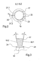
- FIGS. 2 and 3 Reference is made, in which one of the clamping rings 6.1 is shown schematically in several views. The following description applies to both figures, insofar as no explicit reference is made to one of the figures.
- the clamping ring 6.1 has a circumferential clamping collar 17.
- the clamping collar 17 is severed at one point of the circumference by a separating slot 20 throughout.
- the separating slot 20 extends between the opposite ring ends 21.1 and 21.2.
- the distance between the ring ends 21.1 and 21.2 forms the height of the separating slot 20, which in Fig. 2 is indicated by the lowercase letter h.
- the separating slot 20 is very narrow in its height and is preferably designed to be less than 2 mm.
- a plurality of mass balance openings 22 are introduced into the clamping collar 17.
- the number and size of the mass balance openings 22 is designed for a geometric shape of the clamping ring, which is set under load in the spread state of the ring ends 21.1 and 21.2.
- the ring ends 21.1 and 21.2 in the separating slot 20 with a greater distance from each other, so that sets on the periphery of the drive shaft on the side of the separating slots a greater mass loss through the separating slot 20.
- a plurality of mass compensation openings 22 are formed on the opposite side of the separating slot 20, so that the clamping ring 6.1 does not generate any imbalance on the circumference of the drive shaft.
- two opposing clamping surfaces 18.1 and 18.2 are formed on the clamping collar 17 of the clamping ring.
- the clamping surfaces 18.1 and 18.2 have a tilt angle ⁇ relative to a normal.
- the inclination angle ⁇ is identical in both clamping surfaces 18.1 and 18.2 and is preferably in a range of 15 ° to 45 °.
- the clamping surfaces 18.1 and 18.2 act in the operating state - as explained later - with pressure surfaces 25 of the clamping sleeves 5.1, 5.2 and 5.3 together.
- a circumferential cylindrical holding web 19 is formed, which in each case forms a projection 24 for each end face of the clamping ring 6.1.
- the holding web 19 is connected to the clamping collar 17 in the central region.
- the retaining web 19 and the clamping collar 17 is severed at several points of the circumference by cutouts 23.
- the cutouts 23 are uniformly distributed on the circumference of the retaining web 19.
- the holder web 19 is severed into a plurality of sections.
- the size and shape of the cutouts 23 is dimensioned such that, despite the use of a solid material, for example, a hard plastic sufficient elasticity of the clamping ring for spreading the ring ends 21.1 and 21.2 results.
- Fig. 1 is the clamping ring 6.1 and the same to the clamping ring 6.1 formed clamping ring 6.2 shown in an expanded position for fixing the winding tube 36.
- the clamping rings 6.1 and 6.2 are held by the winding tubes 5.1, 5.2 and 5.3.
- the bearing end 2 of the drive shaft 1 facing clamping sleeve 5.1 is preferably fixed to the circumference of the drive shaft 1 and forms a stop with an excellent collar 29.
- the clamping sleeve 5.1 At the clamping ring 6.1 facing front end, the clamping sleeve 5.1 a pressure surface 25 and an indentation 26 to a To allow surface contact and contact with the clamping ring 6.1.
- the adjoining clamping sleeve 5.2 is displaceably guided on the circumference of the drive shaft 1 and has in each case a pressure surface 25 and an incision 26 at both front ends.
- the clamping sleeve 5.2 rests with its left pressure surface 25 on the clamping ring 6.1 and with the right pressure surface 25 on the clamping ring 6.2.
- the guided at the end of the drive shaft 1 clamping sleeve 5.3 also has a relation to the clamping ring 6.2 trained pressure surface 25 and an incision 26.
- a cup-shaped front end 14 is formed, so that the clamping sleeve 5.3 surrounds the free end of the drive shaft 1 cup-shaped.
- the clamping sleeves 5.1, 5.2 and 5.3 a plurality of material recesses 28.
- the clamping sleeves 5.2 and 5.3 relative to the circumference of the drive shaft 1 realize small sliding surfaces.
- unnecessary material accumulations are avoided on the circumference of the drive shaft 1.
- the front end 14 of the clamping sleeve 5.3 is connected via a fastening means 35 with a clamping piston 7.
- the tensioning piston 7 is designed as a stepped piston and is guided in a guide opening 8 at the free end face of the drive shaft 1.
- the clamping piston 7 has a guide section 11, which is guided pressure-tight in the guide opening 8.
- a pressure chamber 37 is formed at the closed end of the guide opening 8, which acts on the end face of the guide portion 11.
- the pressure chamber 37 is connected via a fluid channel 15 with a arranged at the bearing end 2 of the drive shaft 1 fluid port 16.
- the clamping piston 7 has a smaller diameter holding portion 13 which protrudes with its free end from the guide opening 8 and is fixedly connected to the front end 14 of the clamping sleeve 5.3.
- a compression spring 10 is held within the guide opening 8, which is supported on the one hand a diameter stage between the guide portion 11 and the holding portion 13 of the clamping piston 7 and on the other hand held by a fixed to the guide opening 8 retaining ring 9.
- the holder ring 9 has an opening in the center, which is penetrated by the holding portion 13 of the clamping piston 7.
- the drive shaft 1 is coupled to the bearing end 2 with an electric motor 32.
- a rotor 33 is fixed to the circumference of the drive shaft 1, which cooperates with an opposite stator 34 of the electric motor 32.
- a roller bearing 31.1 and 31.2 are respectively held in a motor housing 30, in which the drive shaft 1 is mounted with the bearing end 2.
- the bearing end 2 of the drive shaft 1 is provided for this purpose with a plurality of diameter steps.
- the clamping device 4 In order to suspend and tension a winding tube 36 at the beginning of a winding operation on the circumference of the bobbin holder, the clamping device 4 is held in a non-tensioned state. For this purpose, a pressurized fluid is conducted into the fluid channel 15 and pressure chamber 37 via the fluid connection 16. The pressure fluid acting on the end face of the guide section 11 of the tensioning piston 7 generates a fluid force which displaces the tensioning piston 7 against the compression spring 10 in the direction toward the free end of the drive shaft 1 in a release position. As a result, the clamping sleeve 5.3 is also moved to the free end of the drive shaft 1, so that the clamping rings 6.1 and 6.2 released from their tension become. The spreading of the clamping rings 6.1 and 6.2 dissolves and the respective ring ends 21.1 and 21.2 lie with a short distance to each other around the circumference of the drive shaft 1 at. In this state, the winding tubes 36 are changed at the Spulhalter.
- the clamping device 4 is placed in a tensioned state.
- the pressure fluid within the pressure chamber 37 is placed in a pressureless state, so that the tensioning piston 7 is displaced by the spring force of the compression spring 10 in a clamping position in the direction towards the bearing end 2.
- the clamping sleeve 5.3 is also moved over the clamping piston 7 in the direction of the stop 29, so that the sleeve package 5.1, 5.2 and 5.3 is clamped with the intermediate clamping rings 6.1 and 6.2.
- the drive shaft 1 is driven by the tensioning device 4 via the electric motor 32.
- FIG. 1 illustrated embodiment in particular the embodiment of in FIGS. 2 and 3 shown clamping ring is exemplary.
- a clamping device can be realized with similar shapes of the clamping ring, wherein it is essential here that the radial clamping force is generated essentially by a radial spreading of the ring ends of the clamping ring.
Applications Claiming Priority (2)
| Application Number | Priority Date | Filing Date | Title |
|---|---|---|---|
| DE102008013125A DE102008013125A1 (de) | 2008-03-07 | 2008-03-07 | Spulenhalter |
| PCT/EP2009/052469 WO2009109554A1 (de) | 2008-03-07 | 2009-03-02 | Spulenhalter |
Publications (2)
| Publication Number | Publication Date |
|---|---|
| EP2247521A1 EP2247521A1 (de) | 2010-11-10 |
| EP2247521B1 true EP2247521B1 (de) | 2013-08-07 |
Family
ID=40720776
Family Applications (1)
| Application Number | Title | Priority Date | Filing Date |
|---|---|---|---|
| EP09716443.8A Not-in-force EP2247521B1 (de) | 2008-03-07 | 2009-03-02 | Spulenhalter |
Country Status (5)
| Country | Link |
|---|---|
| US (1) | US8523100B2 (zh) |
| EP (1) | EP2247521B1 (zh) |
| CN (1) | CN101959779B (zh) |
| DE (1) | DE102008013125A1 (zh) |
| WO (1) | WO2009109554A1 (zh) |
Families Citing this family (10)
| Publication number | Priority date | Publication date | Assignee | Title |
|---|---|---|---|---|
| US8844859B2 (en) | 2011-05-02 | 2014-09-30 | Illinois Tool Works, Inc. | Expandable chuck for thermal printing ribbon reel |
| US10434292B2 (en) * | 2011-06-24 | 2019-10-08 | Access Closure | Method and devices for flow occlusion during device exchanges |
| CN102658984A (zh) * | 2012-05-02 | 2012-09-12 | 天津三英焊业股份有限公司 | 解卷机 |
| CN103640927A (zh) * | 2013-12-25 | 2014-03-19 | 吴江市菀坪宝得利缝制设备机械厂 | 一种绕线套胀接管 |
| EP3225577A1 (en) * | 2016-03-31 | 2017-10-04 | Olympic Holding B.V. | Cantilever expansion shaft |
| KR101880205B1 (ko) * | 2017-05-16 | 2018-07-20 | 일진에이테크 주식회사 | 지관 척킹 장치 |
| DE102018000259A1 (de) * | 2018-01-13 | 2019-07-18 | Oerlikon Textile Gmbh & Co. Kg | Adaptereinrichtung zum Halten zumindest einer Spulhülse |
| CN109052013A (zh) * | 2018-09-29 | 2018-12-21 | 张家港欣欣高纤股份有限公司 | 一种涤纶长丝产品加工用高速纺丝机对筒管夹紧装置 |
| GB2590372B (en) * | 2019-12-11 | 2022-02-09 | Dyson Technology Ltd | A drum for reeling sheet material |
| DE102021101530A1 (de) * | 2021-01-25 | 2022-07-28 | Achenbach Buschhütten GmbH & Co. KG | Haspel zum Aufwickeln oder Abwickeln von bandförmigen Material und Verfahren |
Family Cites Families (9)
| Publication number | Priority date | Publication date | Assignee | Title |
|---|---|---|---|---|
| DE628962C (de) | 1934-03-23 | 1936-04-20 | Feldmuehle A G Vorm Loeb Schoe | Aufwickelkoerper fuer frisch gesponnene Kunstseidefaeden mit radial bewegbaren Laengsteilen |
| GB970526A (en) | 1963-08-09 | 1964-09-23 | Ind Devices Inc | Collet assembly for use with thread winding means |
| CH443993A (de) | 1966-12-13 | 1967-09-15 | Rieter Ag Maschf | Spulenspanndorn |
| US4241883A (en) * | 1979-08-24 | 1980-12-30 | E. I. Du Pont De Nemours And Company | Manually operated bobbin chuck |
| JPS5867845U (ja) | 1981-10-30 | 1983-05-09 | 帝人株式会社 | ボビンの緊着装置 |
| JP2567267B2 (ja) | 1988-02-15 | 1996-12-25 | 帝人製機株式会社 | ボビンの緊着装置 |
| JP3198736B2 (ja) | 1993-07-14 | 2001-08-13 | 東レ株式会社 | ボビン把持装置およびボビンホルダ |
| JP3041292B1 (ja) | 1999-03-16 | 2000-05-15 | 東レエンジニアリング株式会社 | 巻取機のボビン保持装置 |
| JP2003276944A (ja) | 2002-03-27 | 2003-10-02 | Murata Mach Ltd | ボビンチャック装置 |
-
2008
- 2008-03-07 DE DE102008013125A patent/DE102008013125A1/de not_active Withdrawn
-
2009
- 2009-03-02 US US12/921,161 patent/US8523100B2/en not_active Expired - Fee Related
- 2009-03-02 EP EP09716443.8A patent/EP2247521B1/de not_active Not-in-force
- 2009-03-02 WO PCT/EP2009/052469 patent/WO2009109554A1/de active Application Filing
- 2009-03-02 CN CN200980108100.3A patent/CN101959779B/zh not_active Expired - Fee Related
Also Published As
| Publication number | Publication date |
|---|---|
| CN101959779B (zh) | 2013-02-13 |
| EP2247521A1 (de) | 2010-11-10 |
| WO2009109554A1 (de) | 2009-09-11 |
| US20110062275A1 (en) | 2011-03-17 |
| CN101959779A (zh) | 2011-01-26 |
| US8523100B2 (en) | 2013-09-03 |
| DE102008013125A1 (de) | 2009-09-10 |
Similar Documents
| Publication | Publication Date | Title |
|---|---|---|
| EP2247521B1 (de) | Spulenhalter | |
| EP2024265B1 (de) | Klemmvorrichtung | |
| EP2523884B1 (de) | Spulspindel | |
| DE2912725C2 (de) | Lagerspannvorrichtung für ein Gasturbinentriebwerk | |
| WO1995028248A1 (de) | Vorrichtung zum bruchtrennen von lagerdeckeln fluchtend angeordneter lagerbohrungen in lageranordnungen eines maschinenteils | |
| WO2003055778A1 (de) | Spulspindel mit erhöhter eigenfrequenz | |
| EP0571580B1 (de) | Friktionsfalschdrallaggregat | |
| EP0401171A2 (de) | Trägerstreifen für pulverkraftbetriebene Setzgeräte | |
| EP0090939B1 (de) | Offenend-Spinnrotor | |
| DE19819824B4 (de) | Torsionsschwingungsdämpfer mit einer Dämpfungseinrichtung | |
| CH695563A5 (de) | Vorrichtung zum Führen oder Aufwickeln eines laufenden Fadens. | |
| EP1604113A1 (de) | Druckstift und axialkolbenmaschinen mit diesem druckstift | |
| EP3385207B1 (de) | Spindel für einen wickler | |
| DE10310306A1 (de) | Vorrichtung zum Spannen einer Statorwicklung | |
| DE2848781A1 (de) | Elastische wellenkupplung | |
| WO2016150737A1 (de) | Spulspindel | |
| DE4407260A1 (de) | Kupplung mit einer Mehrzahl von Federn zur Erzeugung der Anpreßkraft | |
| DE3044315A1 (de) | Huelsenspannvorrichtung fuer mehrfach-spulentraeger | |
| DE19721335C2 (de) | Vorrichtung zur Fixierung eines Rotors auf einer Antriebswelle | |
| EP1423623B1 (de) | Freilauf mit einem mit faserverstärktem kunststoff umwickelten freilaufaussenring | |
| DE3033302A1 (de) | Drehschwingungsdaempfer bzw. schwingungsdaempfende und elastische kupplung | |
| EP0426097A2 (de) | Werkzeugträger für Rotationswerkzeuge, insbesondere Kreissägeblätter, Zerspaner usw. | |
| DE10151860B4 (de) | Spannwelle, System aus Spannwelle und Hülse und Rotationsdruckmaschine sowie Verfahren zur dynamischen Stabilisierung einer Spannwelle | |
| WO2016146465A1 (de) | Spulspindel | |
| DE2854715A1 (de) | Spannfutter in spulmaschinen zur aufnahme eines spulentraegers |
Legal Events
| Date | Code | Title | Description |
|---|---|---|---|
| PUAI | Public reference made under article 153(3) epc to a published international application that has entered the european phase |
Free format text: ORIGINAL CODE: 0009012 |
|
| 17P | Request for examination filed |
Effective date: 20100720 |
|
| AK | Designated contracting states |
Kind code of ref document: A1 Designated state(s): AT BE BG CH CY CZ DE DK EE ES FI FR GB GR HR HU IE IS IT LI LT LU LV MC MK MT NL NO PL PT RO SE SI SK TR |
|
| AX | Request for extension of the european patent |
Extension state: AL BA RS |
|
| DAX | Request for extension of the european patent (deleted) | ||
| 17Q | First examination report despatched |
Effective date: 20120417 |
|
| GRAP | Despatch of communication of intention to grant a patent |
Free format text: ORIGINAL CODE: EPIDOSNIGR1 |
|
| GRAS | Grant fee paid |
Free format text: ORIGINAL CODE: EPIDOSNIGR3 |
|
| GRAP | Despatch of communication of intention to grant a patent |
Free format text: ORIGINAL CODE: EPIDOSNIGR1 |
|
| INTG | Intention to grant announced |
Effective date: 20130606 |
|
| GRAA | (expected) grant |
Free format text: ORIGINAL CODE: 0009210 |
|
| AK | Designated contracting states |
Kind code of ref document: B1 Designated state(s): AT BE BG CH CY CZ DE DK EE ES FI FR GB GR HR HU IE IS IT LI LT LU LV MC MK MT NL NO PL PT RO SE SI SK TR |
|
| REG | Reference to a national code |
Ref country code: GB Ref legal event code: FG4D Free format text: NOT ENGLISH |
|
| REG | Reference to a national code |
Ref country code: CH Ref legal event code: EP Ref country code: AT Ref legal event code: REF Ref document number: 625668 Country of ref document: AT Kind code of ref document: T Effective date: 20130815 |
|
| REG | Reference to a national code |
Ref country code: IE Ref legal event code: FG4D Free format text: LANGUAGE OF EP DOCUMENT: GERMAN |
|
| REG | Reference to a national code |
Ref country code: DE Ref legal event code: R096 Ref document number: 502009007717 Country of ref document: DE Effective date: 20131002 |
|
| REG | Reference to a national code |
Ref country code: NL Ref legal event code: VDEP Effective date: 20130807 |
|
| REG | Reference to a national code |
Ref country code: LT Ref legal event code: MG4D |
|
| PG25 | Lapsed in a contracting state [announced via postgrant information from national office to epo] |
Ref country code: IS Free format text: LAPSE BECAUSE OF FAILURE TO SUBMIT A TRANSLATION OF THE DESCRIPTION OR TO PAY THE FEE WITHIN THE PRESCRIBED TIME-LIMIT Effective date: 20131207 Ref country code: CY Free format text: LAPSE BECAUSE OF FAILURE TO SUBMIT A TRANSLATION OF THE DESCRIPTION OR TO PAY THE FEE WITHIN THE PRESCRIBED TIME-LIMIT Effective date: 20130911 Ref country code: PT Free format text: LAPSE BECAUSE OF FAILURE TO SUBMIT A TRANSLATION OF THE DESCRIPTION OR TO PAY THE FEE WITHIN THE PRESCRIBED TIME-LIMIT Effective date: 20131209 Ref country code: LT Free format text: LAPSE BECAUSE OF FAILURE TO SUBMIT A TRANSLATION OF THE DESCRIPTION OR TO PAY THE FEE WITHIN THE PRESCRIBED TIME-LIMIT Effective date: 20130807 Ref country code: HR Free format text: LAPSE BECAUSE OF FAILURE TO SUBMIT A TRANSLATION OF THE DESCRIPTION OR TO PAY THE FEE WITHIN THE PRESCRIBED TIME-LIMIT Effective date: 20130807 Ref country code: NO Free format text: LAPSE BECAUSE OF FAILURE TO SUBMIT A TRANSLATION OF THE DESCRIPTION OR TO PAY THE FEE WITHIN THE PRESCRIBED TIME-LIMIT Effective date: 20131107 Ref country code: SE Free format text: LAPSE BECAUSE OF FAILURE TO SUBMIT A TRANSLATION OF THE DESCRIPTION OR TO PAY THE FEE WITHIN THE PRESCRIBED TIME-LIMIT Effective date: 20130807 |
|
| PG25 | Lapsed in a contracting state [announced via postgrant information from national office to epo] |
Ref country code: LV Free format text: LAPSE BECAUSE OF FAILURE TO SUBMIT A TRANSLATION OF THE DESCRIPTION OR TO PAY THE FEE WITHIN THE PRESCRIBED TIME-LIMIT Effective date: 20130807 Ref country code: NL Free format text: LAPSE BECAUSE OF FAILURE TO SUBMIT A TRANSLATION OF THE DESCRIPTION OR TO PAY THE FEE WITHIN THE PRESCRIBED TIME-LIMIT Effective date: 20130807 Ref country code: SI Free format text: LAPSE BECAUSE OF FAILURE TO SUBMIT A TRANSLATION OF THE DESCRIPTION OR TO PAY THE FEE WITHIN THE PRESCRIBED TIME-LIMIT Effective date: 20130807 Ref country code: PL Free format text: LAPSE BECAUSE OF FAILURE TO SUBMIT A TRANSLATION OF THE DESCRIPTION OR TO PAY THE FEE WITHIN THE PRESCRIBED TIME-LIMIT Effective date: 20130807 Ref country code: GR Free format text: LAPSE BECAUSE OF FAILURE TO SUBMIT A TRANSLATION OF THE DESCRIPTION OR TO PAY THE FEE WITHIN THE PRESCRIBED TIME-LIMIT Effective date: 20131108 Ref country code: FI Free format text: LAPSE BECAUSE OF FAILURE TO SUBMIT A TRANSLATION OF THE DESCRIPTION OR TO PAY THE FEE WITHIN THE PRESCRIBED TIME-LIMIT Effective date: 20130807 |
|
| PG25 | Lapsed in a contracting state [announced via postgrant information from national office to epo] |
Ref country code: CY Free format text: LAPSE BECAUSE OF FAILURE TO SUBMIT A TRANSLATION OF THE DESCRIPTION OR TO PAY THE FEE WITHIN THE PRESCRIBED TIME-LIMIT Effective date: 20130807 |
|
| PG25 | Lapsed in a contracting state [announced via postgrant information from national office to epo] |
Ref country code: CZ Free format text: LAPSE BECAUSE OF FAILURE TO SUBMIT A TRANSLATION OF THE DESCRIPTION OR TO PAY THE FEE WITHIN THE PRESCRIBED TIME-LIMIT Effective date: 20130807 Ref country code: EE Free format text: LAPSE BECAUSE OF FAILURE TO SUBMIT A TRANSLATION OF THE DESCRIPTION OR TO PAY THE FEE WITHIN THE PRESCRIBED TIME-LIMIT Effective date: 20130807 Ref country code: RO Free format text: LAPSE BECAUSE OF FAILURE TO SUBMIT A TRANSLATION OF THE DESCRIPTION OR TO PAY THE FEE WITHIN THE PRESCRIBED TIME-LIMIT Effective date: 20130807 Ref country code: SK Free format text: LAPSE BECAUSE OF FAILURE TO SUBMIT A TRANSLATION OF THE DESCRIPTION OR TO PAY THE FEE WITHIN THE PRESCRIBED TIME-LIMIT Effective date: 20130807 Ref country code: DK Free format text: LAPSE BECAUSE OF FAILURE TO SUBMIT A TRANSLATION OF THE DESCRIPTION OR TO PAY THE FEE WITHIN THE PRESCRIBED TIME-LIMIT Effective date: 20130807 |
|
| PG25 | Lapsed in a contracting state [announced via postgrant information from national office to epo] |
Ref country code: ES Free format text: LAPSE BECAUSE OF FAILURE TO SUBMIT A TRANSLATION OF THE DESCRIPTION OR TO PAY THE FEE WITHIN THE PRESCRIBED TIME-LIMIT Effective date: 20130807 |
|
| PLBE | No opposition filed within time limit |
Free format text: ORIGINAL CODE: 0009261 |
|
| STAA | Information on the status of an ep patent application or granted ep patent |
Free format text: STATUS: NO OPPOSITION FILED WITHIN TIME LIMIT |
|
| 26N | No opposition filed |
Effective date: 20140508 |
|
| REG | Reference to a national code |
Ref country code: DE Ref legal event code: R097 Ref document number: 502009007717 Country of ref document: DE Effective date: 20140508 |
|
| PG25 | Lapsed in a contracting state [announced via postgrant information from national office to epo] |
Ref country code: LU Free format text: LAPSE BECAUSE OF FAILURE TO SUBMIT A TRANSLATION OF THE DESCRIPTION OR TO PAY THE FEE WITHIN THE PRESCRIBED TIME-LIMIT Effective date: 20140302 |
|
| GBPC | Gb: european patent ceased through non-payment of renewal fee |
Effective date: 20140302 |
|
| REG | Reference to a national code |
Ref country code: FR Ref legal event code: ST Effective date: 20141128 |
|
| REG | Reference to a national code |
Ref country code: IE Ref legal event code: MM4A |
|
| PG25 | Lapsed in a contracting state [announced via postgrant information from national office to epo] |
Ref country code: GB Free format text: LAPSE BECAUSE OF NON-PAYMENT OF DUE FEES Effective date: 20140302 Ref country code: IE Free format text: LAPSE BECAUSE OF NON-PAYMENT OF DUE FEES Effective date: 20140302 Ref country code: FR Free format text: LAPSE BECAUSE OF NON-PAYMENT OF DUE FEES Effective date: 20140331 |
|
| PGFP | Annual fee paid to national office [announced via postgrant information from national office to epo] |
Ref country code: IT Payment date: 20150228 Year of fee payment: 7 Ref country code: CH Payment date: 20150319 Year of fee payment: 7 |
|
| PGFP | Annual fee paid to national office [announced via postgrant information from national office to epo] |
Ref country code: TR Payment date: 20150227 Year of fee payment: 7 Ref country code: AT Payment date: 20150323 Year of fee payment: 7 |
|
| PGFP | Annual fee paid to national office [announced via postgrant information from national office to epo] |
Ref country code: BE Payment date: 20150318 Year of fee payment: 7 |
|
| PGFP | Annual fee paid to national office [announced via postgrant information from national office to epo] |
Ref country code: DE Payment date: 20150330 Year of fee payment: 7 |
|
| PG25 | Lapsed in a contracting state [announced via postgrant information from national office to epo] |
Ref country code: MT Free format text: LAPSE BECAUSE OF FAILURE TO SUBMIT A TRANSLATION OF THE DESCRIPTION OR TO PAY THE FEE WITHIN THE PRESCRIBED TIME-LIMIT Effective date: 20130807 |
|
| PG25 | Lapsed in a contracting state [announced via postgrant information from national office to epo] |
Ref country code: BG Free format text: LAPSE BECAUSE OF FAILURE TO SUBMIT A TRANSLATION OF THE DESCRIPTION OR TO PAY THE FEE WITHIN THE PRESCRIBED TIME-LIMIT Effective date: 20130807 Ref country code: MC Free format text: LAPSE BECAUSE OF FAILURE TO SUBMIT A TRANSLATION OF THE DESCRIPTION OR TO PAY THE FEE WITHIN THE PRESCRIBED TIME-LIMIT Effective date: 20130807 |
|
| PG25 | Lapsed in a contracting state [announced via postgrant information from national office to epo] |
Ref country code: HU Free format text: LAPSE BECAUSE OF FAILURE TO SUBMIT A TRANSLATION OF THE DESCRIPTION OR TO PAY THE FEE WITHIN THE PRESCRIBED TIME-LIMIT; INVALID AB INITIO Effective date: 20090302 |
|
| PG25 | Lapsed in a contracting state [announced via postgrant information from national office to epo] |
Ref country code: BE Free format text: LAPSE BECAUSE OF NON-PAYMENT OF DUE FEES Effective date: 20160331 |
|
| REG | Reference to a national code |
Ref country code: DE Ref legal event code: R119 Ref document number: 502009007717 Country of ref document: DE |
|
| REG | Reference to a national code |
Ref country code: CH Ref legal event code: PL |
|
| REG | Reference to a national code |
Ref country code: AT Ref legal event code: MM01 Ref document number: 625668 Country of ref document: AT Kind code of ref document: T Effective date: 20160302 |
|
| PG25 | Lapsed in a contracting state [announced via postgrant information from national office to epo] |
Ref country code: CH Free format text: LAPSE BECAUSE OF NON-PAYMENT OF DUE FEES Effective date: 20160331 Ref country code: DE Free format text: LAPSE BECAUSE OF NON-PAYMENT OF DUE FEES Effective date: 20161001 Ref country code: LI Free format text: LAPSE BECAUSE OF NON-PAYMENT OF DUE FEES Effective date: 20160331 |
|
| PG25 | Lapsed in a contracting state [announced via postgrant information from national office to epo] |
Ref country code: IT Free format text: LAPSE BECAUSE OF NON-PAYMENT OF DUE FEES Effective date: 20160302 Ref country code: AT Free format text: LAPSE BECAUSE OF NON-PAYMENT OF DUE FEES Effective date: 20160302 |
|
| PG25 | Lapsed in a contracting state [announced via postgrant information from national office to epo] |
Ref country code: MK Free format text: LAPSE BECAUSE OF FAILURE TO SUBMIT A TRANSLATION OF THE DESCRIPTION OR TO PAY THE FEE WITHIN THE PRESCRIBED TIME-LIMIT Effective date: 20130807 |
|
| PG25 | Lapsed in a contracting state [announced via postgrant information from national office to epo] |
Ref country code: TR Free format text: LAPSE BECAUSE OF NON-PAYMENT OF DUE FEES Effective date: 20160302 |