EP2246972A2 - Methode zur Regelung eines Drehstrom-Asynchronmotors - Google Patents
Methode zur Regelung eines Drehstrom-Asynchronmotors Download PDFInfo
- Publication number
- EP2246972A2 EP2246972A2 EP10006721A EP10006721A EP2246972A2 EP 2246972 A2 EP2246972 A2 EP 2246972A2 EP 10006721 A EP10006721 A EP 10006721A EP 10006721 A EP10006721 A EP 10006721A EP 2246972 A2 EP2246972 A2 EP 2246972A2
- Authority
- EP
- European Patent Office
- Prior art keywords
- value
- axis
- output
- voltage
- conversion unit
- Prior art date
- Legal status (The legal status is an assumption and is not a legal conclusion. Google has not performed a legal analysis and makes no representation as to the accuracy of the status listed.)
- Granted
Links
- 238000000034 method Methods 0.000 title claims abstract description 52
- 230000006698 induction Effects 0.000 title claims abstract description 48
- 238000006243 chemical reaction Methods 0.000 claims abstract description 47
- 230000004907 flux Effects 0.000 claims description 41
- 230000000694 effects Effects 0.000 description 22
- 239000000203 mixture Substances 0.000 description 20
- 238000010586 diagram Methods 0.000 description 14
- 230000007423 decrease Effects 0.000 description 12
- 230000001131 transforming effect Effects 0.000 description 2
- XEEYBQQBJWHFJM-UHFFFAOYSA-N Iron Chemical group [Fe] XEEYBQQBJWHFJM-UHFFFAOYSA-N 0.000 description 1
- 230000015556 catabolic process Effects 0.000 description 1
- 230000000295 complement effect Effects 0.000 description 1
- 238000011217 control strategy Methods 0.000 description 1
- 238000006731 degradation reaction Methods 0.000 description 1
- 230000008929 regeneration Effects 0.000 description 1
- 238000011069 regeneration method Methods 0.000 description 1
Images


Classifications
-
- H—ELECTRICITY
- H02—GENERATION; CONVERSION OR DISTRIBUTION OF ELECTRIC POWER
- H02P—CONTROL OR REGULATION OF ELECTRIC MOTORS, ELECTRIC GENERATORS OR DYNAMO-ELECTRIC CONVERTERS; CONTROLLING TRANSFORMERS, REACTORS OR CHOKE COILS
- H02P21/00—Arrangements or methods for the control of electric machines by vector control, e.g. by control of field orientation
- H02P21/04—Arrangements or methods for the control of electric machines by vector control, e.g. by control of field orientation specially adapted for very low speeds
-
- H—ELECTRICITY
- H02—GENERATION; CONVERSION OR DISTRIBUTION OF ELECTRIC POWER
- H02P—CONTROL OR REGULATION OF ELECTRIC MOTORS, ELECTRIC GENERATORS OR DYNAMO-ELECTRIC CONVERTERS; CONTROLLING TRANSFORMERS, REACTORS OR CHOKE COILS
- H02P21/00—Arrangements or methods for the control of electric machines by vector control, e.g. by control of field orientation
- H02P21/14—Estimation or adaptation of machine parameters, e.g. flux, current or voltage
- H02P21/18—Estimation of position or speed
-
- H—ELECTRICITY
- H02—GENERATION; CONVERSION OR DISTRIBUTION OF ELECTRIC POWER
- H02P—CONTROL OR REGULATION OF ELECTRIC MOTORS, ELECTRIC GENERATORS OR DYNAMO-ELECTRIC CONVERTERS; CONTROLLING TRANSFORMERS, REACTORS OR CHOKE COILS
- H02P21/00—Arrangements or methods for the control of electric machines by vector control, e.g. by control of field orientation
- H02P21/24—Vector control not involving the use of rotor position or rotor speed sensors
- H02P21/26—Rotor flux based control
-
- H—ELECTRICITY
- H02—GENERATION; CONVERSION OR DISTRIBUTION OF ELECTRIC POWER
- H02P—CONTROL OR REGULATION OF ELECTRIC MOTORS, ELECTRIC GENERATORS OR DYNAMO-ELECTRIC CONVERTERS; CONTROLLING TRANSFORMERS, REACTORS OR CHOKE COILS
- H02P2207/00—Indexing scheme relating to controlling arrangements characterised by the type of motor
- H02P2207/01—Asynchronous machines
Definitions
- the present invention relates to a method of controlling the rotational speed (hereafter referred to as the speed) of an induction motor, and especially to a vector control method without a speed sensor, capable of achieving a highly accurate speed control without a speed sensor, which can obtain high torque from a zero speed range.
- the output frequency of a power-conversion unit for the induction motor is usually corresponding to the sum of the speed and the calculated slip frequency.
- the output frequency of the power-conversion unit is controlled with an estimated value of the speed in place of a detected value of the speed.
- the estimated value of the speed includes an error, the actual slip frequency shifts from the target reference value.
- the magnetic flux (hereafter referred to as the flux) in the induction motor varies according to the torque, and accordingly the torque generated by the induction motor is not proportional to the torque current, which in turn causes a shortage of torque in an extreme case.
- An object of the present invention is to provide a method of accurately and efficiently controlling an induction motor without receiving effects of errors in an estimated speed due to changes in constants of the induction motor.
- the present invention provides a method and apparatus of controlling an induction motor with a rotational speed-control apparatus, which includes a power-conversion unit, for so controlling a frequency and current output from said power-conversion unit in accordance with a rotational speed instruction value that if said rotational speed instruction value is less than a predetermined value, current output from said power-conversion unit is controlled at a predetermined value larger than that in an ordinary no-load operation, and the value of said current is corrected corresponding to a value which is obtained by adding an estimated slip frequency value calculated based on the value of said voltage output from said power-conversion unit to a calculated slip frequency value calculated by using a value of current output from said power-conversion unit.
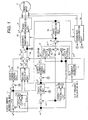
- Fig. 1 shows the schematic circuit composition of a speed-control apparatus for an induction motor of an embodiment according to the present invention.
- Reference numbers 1, 2, and 3 indicate an induction motor, a power-conversion unit for outputting output voltages proportional to voltage instruction values V1*, and a coordinate-transformation unit for transforming the coordinates of output currents iu and iw and calculating d-axis and q-axis currents Id and Iq, respectively.
- Reference number 4 indicates a speed-estimation unit for calculating an estimated speed ⁇ r ⁇ based on a q-axis voltage instruction value Vq** and the current Iq.
- Reference number 5 indicates a speed-control unit for outputting a q-axis current instruction value Iq* corresponding to a difference between a speed instruction value ⁇ r* and the estimated speed ⁇ r ⁇ , which further includes a limiter for limiting the instruction value Iq* corresponding to the value of Id.
- Reference numbers 6 and 7 indicate a q-axis current-control unit for outputting ⁇ q corresponding to the values Iq* and Iq, and a slip frequency-calculation unit in which a device 71 is a slip frequency calculator for obtaining a calculated slip frequency based on the value Iq*, respectively.
- Reference number 8 indicates a switching unit, which includes a multiplier 82 for multiplying ⁇ r ⁇ by the output Ga1 of a function generator 81, a multiplier 84 for multiplying ⁇ r ⁇ by the output Ga2 of a function generator 83, and an adder 85 for summing the outputs from both the multipliers 81 and 84, for switching its output ⁇ r ⁇ between ⁇ r ⁇ and ⁇ r* corresponding to the value of the speed.
- Reference numbers 9 and 10 indicate an adder for obtaining a signal ⁇ 1*by summing the output signal ⁇ r ⁇ of the switching unit 8 and ⁇ s*, and a phase-generation unit for outputting a phase reference value ⁇ by integrating the output frequency instruction value ⁇ 1* of output from the adder 9, respectively.
- Reference number 11 indicates a d-axis current instruction unit including a multiplier 112 for multiplying an additional current value ⁇ Id by the output Ga3 of a function generator 111 and an adder 113 for obtaining a d-axis current instruction value Id** by summing a reference current value Id* and the output of the multiplier 111.
- Reference numbers 12 and 13 indicate a d-axis current-control unit for outputting a signal ⁇ d corresponding to a difference between Id** and Id and a voltage-calculation unit for calculating d-axis and q-axis reference voltages Vd* and Vq* based on Id**, Iq*, and ⁇ 1*, respectively .
- reference numbers 14, 15, and 16 indicate an adder for outputting Vd** by summing Vd* and ⁇ d and a coordinate-transformation unit for outputting output-voltage instruction values V1* (for three phases) by transforming the coordinates of Vd** and Vq**.
- the units 8 and 11 are specific to this embodiment.
- the performances of the function generators included in the respective units 8 and 11 are as follows.
- the output Ga1 of the function generator 81 is 0 near the input value 0, and 1 in the range of a large input value, and vice versa as to the output Ga2 of the function generator 83.
- the outputs Ga1 and Ga2 are complementary to each other, which is expressed the equation (1).
- Ga ⁇ 1 + Ga ⁇ 2 1
- the output Ga3 of the function generator 111 is 0 if ⁇ r* is near 0, and 1 if ⁇ r* is in the range of a large value. Accordingly, Id** and Id is increased from the reference value Id* by ⁇ Id. The gradual increase and decrease regions of Ga3 are prepared to smoothly change Id**, and an intermediate value between Id* and Id* + ⁇ Id is output as Id**.
- the operation of the induction motor control system according to this embodiment is explained below.
- the operations of the units or devices 1 - 7, 9, 10, and 12 - 16 are the same as those in the conventional vector control system without a speed sensor.
- the speed is estimated based on the output voltage and current of the power-conversion unit 2, and the speed is controlled by feeding-back the estimated speed ⁇ r ⁇ to the speed-control unit 5. Further, the output frequency of the power-conversion unit 2 is controlled based on the sum of the estimated speed ⁇ r ⁇ and the calculated slip frequency ⁇ s*.
- the difference between the vector control without a speed sensor and the wel-lknown vector control with a speed sensor is that, in the vector control system without a speed sensor, the estimated speed is used in place of the speed detected by a speed sensor attached at an induction motor 1.
- the fundamental operation is common to both the controls.
- the voltage-calculation unit 13 calculates the d and q-axis voltage reference values Vd* and Vq* based on the current instruction values Id** and Iq*, and the output frequency instruction value ⁇ 1*, and the output voltage of the power-conversion unit 2 is controlled according to the calculated voltage reference values Vd* and Vq*.
- the reference voltage values Vd* and Vq* are corrected with ⁇ d and ⁇ q output from the d and q-axis current-control units 12 and 6 so that the current flows Id and Iq agree with their instruction values.
- the slip frequency-control-type vector control is performed, and the torque of the induction motor 1 is controlled in proportion to Iq*.
- the speed-estimation unit 4 calculates the estimated speed value ⁇ r ⁇ based on the equation (3).
- ⁇ ⁇ r ⁇ 1 / 1 + T ⁇ 0 • s L ⁇ 2 * / M * • ⁇ ⁇ 2 ⁇ d * Vq * * - ⁇ ⁇ 1 * • L ⁇ ⁇ * • Id * * - R ⁇ ⁇ * + L ⁇ ⁇ * • s ⁇ Iq
- Fig. 2 shows the calculational function performed based on the equation (3) by the speed estimator 4.
- Eq is estimated with the inverse model of the motor 1, and ⁇ r ⁇ is obtained by dividing the estimated Eq by the reference flux.
- the estimated value ⁇ r ⁇ is used as a feed back signal to the speed-control unit 5, and for the calculation of ⁇ 1*.
- the equation (4) used to the calculation of ⁇ 1* is shown below.
- ⁇ r ⁇ is directly used as the output frequency reference value ⁇ 1* to control the output frequency of the power-conversion unit 2.
- ⁇ ⁇ 1 * ⁇ ⁇ r ⁇ + ⁇ ⁇ s *
- the q-axis current instruction value Iq* is calculated corresponding to the speed deviation ( ⁇ r* - ⁇ r ⁇ ). Since the torque of the motor 1 is basically proportional to Iq*, the speed is controlled such that ⁇ r* agrees with ⁇ r ⁇ . In order that the torque of the motor 1 is precisely proportional to Iq*, it is required that the current value Iq of the motor 1 agrees with Iq*, and the flux in the motor 1 is kept at the reference value. To attain the above conditions, it is necessary to control the current values Id and Iq of the motor 1 so as to agree with the respective instruction values Id** and Iq*. To implement the above control, the d and q-axis current-control units 12 and 6 are equipped.
- the reference voltage values Vd* and Vq* corresponding to Vd and Vq can be calculated in advance with the equations (6) using Id**, Iq*, ⁇ 1*, and the characteristic parameters of the motor 1. This calculation is performed by the voltage-calculation unit 13.
- vd r ⁇ 1 • Id - ⁇ ⁇ 1 • L ⁇ ⁇ • Iq
- vq r ⁇ 1 • Iq + ⁇ ⁇ 1 • L ⁇ ⁇ • I ⁇ d + ⁇ ⁇ 1 M / L ⁇ 2 ⁇ ⁇ ⁇ 2 ⁇ d
- the output voltage of the power-conversion unit 2 (the voltage in the motor 1) is basically controlled according to Vd* and Vq*. If a control error exists, the actual current values Id and Iq do not agree with the respective instruction values by performing only the above control. Therefore, the adjustment signals ⁇ d and ⁇ q corresponding to the respective current deviations are obtained by the d and q-axis current-control units 12 and 6, and the output voltage of the power-conversion unit 2 is corrected based on the adjustment signals ⁇ d and ⁇ q so that Id and Iq agree with the respective instruction values.
- the operations which are explained up to here are common to the conventional control method.
- Fig. 3 shows the relationship between the speed ⁇ r and the torque ⁇ m generated in an induction motor controlled by a conventional control method in the speed range near zero.
- the shadowed region in this figure indicates an unstable region in which the decrease of the torque easily happens.
- the range 0.5 - 1 Hz of speed ⁇ r corresponds to an unstable area in the motoring region in which the signs of ⁇ m and ⁇ r are the same, and the range less than several Hz of speed ⁇ r corresponds to an unstable area in the regeneration region in which the sign of ⁇ m is different from the sign of ⁇ r. Also, if the estimation error in ⁇ r ⁇ obtained by the speed-estimation unit 4 increases, the shadowed region is extended, which in turn sometimes makes the on-load operation of the motor 1 at a low speed impossible.
- the estimation error in ⁇ r ⁇ is caused by; changes in the temperature of the primary and secondary resistance values; changes in the leakage-inductance values due to the flux saturation in the iron core of the motor 1; etc. Specifically, the torque of the motor 1 easily decreases in the speed range near zero due to various kinds of causes.
- the control method of this embodiment which is aimed at preventing the decrease of the torque, controls the motor 1 in the speed range near zero with a control principle different from the above conventional control method. This control principle is mentioned below.
- the decrease of the torque is mainly caused by the error in the estimated speed, and two main causes bring anout this error.
- Strategy 1 the output frequency instruction value ⁇ 1* is calculated with the speed instruction value ⁇ r* in place of the estimated speed ⁇ r ⁇ .
- the output frequency of the power-conversion unit 2 is controlled according to the speed instruction value ⁇ r* in the speed region near zero by outputting ⁇ r* from the switching unit 8 in place ⁇ r ⁇ used in the ordinary speed region.
- Strategy 2 the output current of the power-conversion unit2 is controlled at a predetermined value larger than that in the ordinary no-load operation.
- the q-axis current is set to zero, and the d-axis current is controlled at a predetermined value larger than that in the ordinary no-load operation.
- ⁇ Id is added to the reference value by the d-axis current instruction unit 11 so as to control the current Id at a larger value.
- the maximum torque of the motor 1 is required to be larger than the maximum load-torque, it is necessary to control I1 so as to be a value larger than that corresponding to the maximum load-torque. Therefore, Id or Iq is controlled to attain such a value.
- Id or Iq can be set to the predetermined value independent of the speed deviation, since detecting the direction of the load torque based on the estimated speed ⁇ r ⁇ is difficult because of the bad estimation accuracy of speed ⁇ r ⁇ in the speed range near zero, the polarity of Iq* cannot be set. Therefore, a method of setting Id** to the predetermined value, for which setting of the polarity is not necessary, is used in the embodiment shown in Fig. 1 . In this method, as mentioned in Strategy 2, Iq* is set to 0, and Id** is set to the sum of the reference value Id* in the ordinary speed region and ⁇ Id to control Id (corresponds to I1) such that Id corresponds to the maximum load-torque.
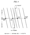
- Fig. 4 shows the relationship between the speed and the torque generated by the induction motor 1 in this embodiment.
- the unstable region (shadowed region) shown in Fig. 3 disappears in Fig. 4 .
- the speed changes by a slip frequency a high torque value can be achieved even in the speed region including and near zero.
- the output or the switching unit 8 shown in Fig. 1 is switched from ⁇ r* to ⁇ r ⁇ , the frequency is controlled using the estimated speed by the same method as that in the conventional control. Moreover, to smoothly switch the output of the switching unit 8, the switching between ⁇ r* and ⁇ r ⁇ is gradually performed so as to prevent a rapid change due to the switching ⁇ 1*.
- the gradual increase and decrease characteristics for the outputs Ga1 and Ga2 of the function generators 81 and 82 are prepared to implement the above objective. Also, in the d-axis current-instruction unit, The gradual increase and decrease characteristics for the output Ga3 are prepared to prevent a rapid change in Id*.
- Iq* is required to be set to a predetermined value or almost zero.
- the limit value IqMaX of Iq* is changed corresponding to Id based on the equation (8).
- IqMAX I ⁇ 1 * 2 - Id 2 where I1* is the setting value of current in the motor 1.
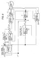
- Fig. 5 shows a schematic block diagram of the circuit composition of a speed-control apparatus for the induction motor 1 of another embodiment according to the present invention.
- This embodiment is an application example of a vector control apparatus without a speed sensor, in which the estimated speed ⁇ r ⁇ is obtained from the output of the q-axis current-control unit 6a.
- the units or devices 1 -3, 5, 7 - 14, and 16 are the same as those in Fig. 1 .
- Reference number 6a indicates a q-axis current-control unit for outputting ⁇ r ⁇ corresponding to the deviation between Iq* and Iq, and the switching unit 8 selects and outputting one of ⁇ r* and ⁇ r ⁇ depending on the value of ⁇ r* as well as that in the previous embodiment.
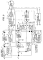
- Fig. 6 shows a schematic block diagram of the circuit composition of a speed-control apparatus for the induction motor 1 of another embodiment according to the present invention.
- This embodiment is an application example of a vector control apparatus without a speed sensor, in which the estimated speed ⁇ 1* is obtained from the output of the q-axis current-control unit 6b.
- the units or devices 1 -3, 5, 7 - 14, and 16 are the same as those in Fig. 1 .
- Reference number 6a indicates a q-axis current-control unit for outputting ⁇ 1* corresponding to the deviation between Iq* and Iq
- reference number 9a indicates a subtracter for obtaining the estimated speed ⁇ r ⁇ by subtracting ⁇ s* from ⁇ 1* and for feeding back ⁇ r ⁇ to the speed-control unit 5.
- the switching unit 8 selects and outputs one of ⁇ r* and ⁇ r ⁇ depending on the value of ⁇ r* as well as that in the previous embodiment.
- ⁇ r ⁇ is output from the switching unit 8
- the output of the current-control unit 6b also corresponds to ⁇ 1*
- Fig. 7 shows a schematic block diagram of the circuit composition of a speed-control apparatus for the induction motor 1 of another embodiment according to the present invention.
- the compositions and operations of the units or devices 1 - 10, and 12 - 16 are the same as those in Fig. 1 .
- Reference number 17 indicates a q-axis current instruction unit for outputting the sum of the set current value Iq0 which is modified depending on the value of ⁇ r* and the output Iq* of the speed-control unit 5, and this q-axis current instruction unit 17 includes a multiplier 172 for multiplying Iq0 by the output Ga4 (0 ⁇ Ga4 ⁇ 1) of a function generator 171 with the gradual increase and decrease characteristics, and an adder 173 for outputting Iq** by adding Iq* to the output of the multiplier 172.
- the operation of the q-axis current instruction unit 17 is explained below. Since Ga4 is "1" in the speed region near zero, and possesses the gradual increase and decrease characteristics (0 ⁇ Ga4 ⁇ 1) in the region other than the speed region near zero, Iq0 is output from the q-axis current instruction unit 17 in the speed region near zero. Therefore, Iq is controlled according to Iq0, and the sufficient torque can be obtained (Iq0 is set to a value which corresponds to the maximum load-torque.) On the other hand, in the region other than the speed region near zero, Iq is controlled based on Iq, which is the same as the conventional control.
- the speed-control unit 5 is equipped, and the control methods in those embodiments are applied to a speed-control method in which the torque is controlled based on Iq* or Iq** output from the speed-control unit 5, the present invention can be applied to a control method without the speed-control unit 5.
- Fig. 8 shows a schematic block diagram of the circuit composition of a speed-control apparatus for the induction motor 1 of another embodiment without the speed-control unit 5.
- the units or devices 1 - 3, 10 - 14, and 16 are the same as those in Fig. 1 .
- Reference number 7a1 indicates a slip frequency calculator for obtaining the calculated slip frequency ⁇ s* based on the q-axis current value Iq
- reference number 9b indicates an adder for obtaining the signal ⁇ 1* by adding the speed instruction value ⁇ r* to the signal ⁇ s*.
- the operation of the control system shown in Fig. 8 is explained below.
- the operation of this system is the same as that of the conventional vector control without a sensor. That is, the output frequency of the power-conversion unit 2 is controlled mostly according to ⁇ r*, and the output voltage of the power-conversion unit 2 is also controlled based on the necessary voltage of the motor 1 which is calculated based on Id**, Iq, and ⁇ 1* by the voltage-calculation unit 13.
- the output voltage and frequency of the power-conversion unit 2 are controlled as explained above, the operation similar to that of a V/f control is performed.
- the induced-electromotive-force (the magnetic flux in the motor 1) is controlled so as to attain a predetermined value by compensating the internal voltage decrease in the motor 1 with the voltage-calculation unit 13 in this embodiment, a sufficient quantity of torque can be obtained to the speed range near zero.
- the d-axis current instruction unit 11 In the speed range near zero, the d-axis current instruction unit 11 output the instruction value Id** obtained by adding ⁇ Id to Id* in order to enhance Id.
- the frequency instruction value ⁇ 1* is controlled according to the speed reference value ⁇ r*, and the d-axis current is controlled so as to be a higher value than that in the ordinary speed range. Accordingly, the shortage of the torque can be dissolved.
- the estimated slip frequency obtained based on the output voltage values is added to the calculated slip frequency obtained using the current instruction value Iq. Furthermore, this sum is used as a new calculated slip frequency to correct the frequency instruction value, and this makes it possible to compensate the deviation of the speed due to the load torque in the whole speed range from zero.
- Fig. 9 shows a schematic block diagram of the circuit composition of a speed control apparatus for the induction motor 1 of another embodiment which implements the above-mentioned control. This embodiment applies the above control to the vector control apparatus without a speed sensor shown in Fig. 1 .
- Reference number 7b indicates a slip frequency-calculation unit for calculating the slip frequency ⁇ s* and the estimated slip frequency ⁇ s ⁇ and obtaining the sum ⁇ s** of ⁇ s* and ⁇ s ⁇ .
- Reference numbers 7b1, 7b2, and 7b3 indicate a slip frequency calculator for obtaining ⁇ s* with the current instruction value Iq*; a slip frequency estimator for obtaining ⁇ s ⁇ with the outputs ⁇ d and ⁇ q of the current-control units 12 and 6, and the output frequency instruction value ⁇ 1*; and an adder for obtaining the sum of ⁇ s* and ⁇ s ⁇ ; respectively.
- the output of the adder 9 agrees with ( ⁇ r*+ ⁇ s ⁇ ) in the speed range near zero, and with ( ⁇ s ⁇ •Ga1 + ⁇ r*•Ga2 + ⁇ s ⁇ + ⁇ s*) in the range other than the speed range near zero.
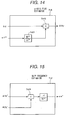
- the slip frequency estimator 7b2 is explained below. First, the composition of the estimator 7b2 is explained with reference to Fig. 10 .
- ⁇ 1* input to the estimator 7b2 is multiplied by a coefficient (M*/L2*), and further by a d-axis flux reference value ⁇ 2d*, and the multiplication result is input to an adder 7b22 along with ⁇ q. Furthermore, ⁇ q and the output signal of the adder 7b22 are input to a divider 7b23. The output signal of the divider 7b23 is multiplied by the reciprocal (1/T2*) of the secondary time constant of the motor 1, and the estimated slip frequency ⁇ s ⁇ is output from the slip frequency estimator 7b2.
- ⁇ d and ⁇ q in the equations (11) are expressed by the equations (12).
- the estimated slip frequency ⁇ s ⁇ can be obtained.
- ⁇ ⁇ s ⁇ 1 / T ⁇ 2 * ⁇ d / ⁇ q + ⁇ ⁇ 1 * M * / L ⁇ 2 * ⁇ ⁇ ⁇ 2 ⁇ d *
- the current instruction value Iq* is generated by the speed-control unit 5.
- the estimated slip frequency ⁇ s ⁇ is obtained using Iq* as shown by the equation (16).
- ⁇ ⁇ s * Iq * • M * / T ⁇ 2 * • ⁇ ⁇ 2 ⁇ d *
- the output frequency instruction value ⁇ 1* is obtained by adding the sum ⁇ s** of ⁇ s ⁇ obtained by the equation (15) and ⁇ s* obtained by the equation (16) to the output ⁇ s ⁇ of the switching unit 8.
- ⁇ ⁇ 1 * ⁇ ⁇ r ⁇ ⁇ + ⁇ ⁇ s * + ⁇ ⁇ s ⁇
- Fig. 11 shows the relationship between the speed and the torque generated in an induction motor controlled using the above slip frequency-compensation method according to the present invention.
- ⁇ s ⁇ is calculated using ⁇ d and ⁇ q in this embodiment shown in Fig. 9
- ⁇ s ⁇ can also be obtained using the induced-electromotive force values ed ⁇ and eq ⁇ calculated from the voltage instruction values Vd** and Vq**.
- ⁇ s ⁇ can be calculated by the equation (19) using ⁇ 2d ⁇ and ⁇ 2q ⁇ , or ed ⁇ and ed ⁇ .
- Iq 0, and the effect of leakage inductance voltage-decrease is small to be neglected (even if L ⁇ ⁇ L ⁇ *)
- Vq* is expressed by the equation (20).
- ⁇ d is obtained by the equations (12)
- ⁇ s ⁇ can be calculated by the equation (21) using ⁇ d and Vq*.
- ⁇ ⁇ s ⁇ 1 / T ⁇ 2 * ⁇ ⁇ d / Vq *
- slip frequency-calculation unit 7b shown in Fig. 9 is used in the above embodiments, the same effects as those of the above embodiment can be obtained using a slip frequency-calculation unit 7c shown in Fig. 12 .
- the unit 7c is the slip frequency-calculation unit for calculating the sum ⁇ s** of ⁇ s* and ⁇ s ⁇ , which includes a slip frequency calculator 7c1 for obtaining ⁇ s* using Id and ⁇ 2d ⁇ ; a slip frequency estimator 7c2 for obtaining ⁇ s ⁇ using ⁇ 2d ⁇ and ⁇ 2q ⁇ ; an adder 7c3 for adding ⁇ s ⁇ to ⁇ s*; a d-axis flux estimator 7c4 for calculating ⁇ 2d ⁇ using ⁇ q and ⁇ 1*; and a q-axis flux estimator 7c5 for calculating ⁇ 2q ⁇ using ⁇ d and ⁇ 1*.
- the d-axis flux estimator 7c4 which is one of the elements composing the slip frequency-calculation unit 7c, is explained below with reference to Fig. 13 .
- ⁇ 1* input to the estimator 7c4 is multiplied by the coefficient (M*/L2*), and further by the d-axis flux reference value ⁇ 2d*, and the multiplication result is input to the adder 7c42 along with ⁇ q. Further, the output of the adder 7c42 and the value ⁇ 1* (M*/L2*) are input to a divider 7c43, and the divider 7c43 outputs the estimated flux ⁇ 2d ⁇ .
- ⁇ 1* input to the estimator 7c5 is multiplied by the coefficient (M*/L2*), and the multiplication result is input to the divider 7c52 along with ⁇ d. Further, the divider 7c52 outputs the estimated flux ⁇ 2q ⁇ .
- the composition of the slip frequency estimator 7c2 for calculating ⁇ s ⁇ using the calculated ⁇ 2d ⁇ and ⁇ 2q ⁇ is shown in Fig. 15 .
- the estimated ⁇ 2d ⁇ and ⁇ 2q ⁇ input to the slip frequency estimator 7c2 are input to a divider 7c21.
- the output signal of the divider 7c21 is multiplied by the reciprocal (1/T2*) of the secondary time constant of the motor1, and the estimator 7c2 outputs the estimated slip frequency ⁇ s ⁇ . Further, the frequency instruction value is corrected with the obtained ⁇ s ⁇ and ⁇ s*.
- the estimated fluxes ⁇ 2d ⁇ and ⁇ 2q ⁇ are obtained by the equations (22) based on the output voltage values, and ⁇ s ⁇ and ⁇ s* are further calculated using the estimated fluxes ⁇ 2d ⁇ and ⁇ 2q ⁇ as shown by the equations (23).
- the speed is controlled according to ⁇ 1* which is calculated based on the equations (17) using the obtained ⁇ s ⁇ and ⁇ s*.
- the unit 7d is a slip frequency-calculation unit for obtaining the sum ⁇ s** of ⁇ s* and ⁇ s ⁇ , which includes a slip frequency calculator 7d1 for obtaining ⁇ s* using Iq* and ⁇ 2d ⁇ ; a slip frequency estimator 7d2 for obtaining ⁇ s ⁇ using ⁇ 2d ⁇ and ⁇ 2q ⁇ ; an adder 7d3 for adding ⁇ s ⁇ to ⁇ s*; and a flux estimator 7d4 for calculating ⁇ 2d ⁇ and ⁇ 2q ⁇ using Vd** and Vq**, and ⁇ 1*.
- a slip frequency calculator 7d1 for obtaining ⁇ s* using Iq* and ⁇ 2d ⁇
- a slip frequency estimator 7d2 for obtaining ⁇ s ⁇ using ⁇ 2d ⁇ and ⁇ 2q ⁇
- an adder 7d3 for adding ⁇ s ⁇ to ⁇ s*
- a flux estimator 7d4 for calculating ⁇ 2d ⁇ and ⁇ 2q ⁇ using Vd** and Vq**
- composition of the flux estimator 7d4 which is one of elements composing the unit 7d, is shown in Fig. 17 .
- Vd**, the calculated resistance voltage-decrease value (r1*•Id*), and the calculated leakage inductance voltage-decrease value (- ⁇ 1*•L ⁇ *•Iq*) are input to a subtracter 7d41. Further, by multiplying ⁇ 1* by the coefficient (M*/L2*), and further by ⁇ 2q ⁇ , the estimated d-axis induced-electromotive force ed ⁇ is obtained. The obtained ed ⁇ is input to a subtracter 7d43 along with the output signal of the subtracter 7d41. Furthermore, the output signal of the subtracter 7d43 is input to an integrator 7d44, and the estimated flux ⁇ 2d ⁇ is output from the integrator 7d44.
- Vq**, the calculated resistance voltage-decrease value (r1*•Iq*), and the calculated leakage inductance voltage-decrease value (- ⁇ 1*•L ⁇ *•Id**) are input to a subtracter 7d45.
- the estimated q-axis induced-electromotive force eq ⁇ is obtained.
- the obtained eq ⁇ is input to a subtracter 7d46 along with the output signal of the subtracter 7d45.
- the output signal of the subtracter 7d46 is input to an integrator 7d47, and the estimated flux ⁇ 2q ⁇ is output from the integrator 7d47.
- ⁇ 2d ⁇ and ⁇ 2q ⁇ are obtained by the equations (24) based on the output voltage, and ⁇ s ⁇ is then calculated.
- ⁇ 2d ⁇ and ⁇ 2q ⁇ are obtained with the flux estimator 7d4 using the voltage instruction values Vd** and, and Vq**, and the calculator 7d1 and the estimator 7d2 shown in Fig. 16 calculate ⁇ s* and ⁇ s ⁇ , respectively, according to the equations (23). Further, the adder 7d3 adds ⁇ s* to ⁇ s ⁇ , and the frequency instruction value ⁇ 1* is corrected with the sum ⁇ s**.
- the d-axis current Id is controlled to be constant independent of the load torque, but the operational efficiency deteriorates in an operation with light load-torque.
- the operational efficiency in the operation with light load-torque can be improved by correcting the current instruction value Id**, corresponding to a estimated torque ⁇ m ⁇ .
- Fig. 18 shows the circuit composition of a speed-control apparatus for an induction motor of an embodiment in which this speed control method is used.
- the above q-axis current-correction method according to this control method is applied to the control apparatus shown in Fig. 1 .
- Reference number 18 indicates a torque estimator for calculating the output torque of the motor 1 based on the voltage instruction values Vd** and Vq**, the detected current values Id and Iq, and the frequency instruction value ⁇ 1*.
- the output signal ⁇ m ⁇ is input to a function generator 11a1 in the d-axis current instruction unit 11a.
- the function generator 11a1 calculates a correction gain Ga5 (0 ⁇ Ga5 ⁇ 1) based on the output signal ⁇ m ⁇ .
- a multiplier 11a1 the increment ⁇ Id* of the current instruction value is multiplied by the above Ga5. Further, Id** is obtained by adding Id* to the result of the multiplication, and the sum is output from the d-axis current instruction unit 11a.
- a torque estimator 18 is explained. The estimator 18 performs the calculation shown by the equation (25) based on Vd** and Vq**, Id and Iq, and ⁇ 1*.
- ⁇ ⁇ m ⁇ Vd * * • Id + Vq * * • Iq / ⁇ ⁇ 1 *
- Id** which corresponds to the load torque is calculated according to the equation (26) using ⁇ m ⁇ obtained by the above equation (25).
- Id * * Id * + F ⁇ ⁇ m ⁇ • ⁇ Id *
- Fig. 19 shows a schematic block diagram of the circuit composition of a speed-control apparatus for an induction motor of this embodiment.
- This embodiment is an example of a control method correcting Id** by using ⁇ s**, which is applied to the apparatus shown in Fig. 1 .
- Reference number 11b indicates a d-axis current instruction unit for calculating the gain Ga6 corrected with ⁇ s**.
- the calculated slip frequency ⁇ s** is input to a function generator 11b1 in the instruction unit 11b.
- the function generator 11b1 calculates the gain Ga6 (0 ⁇ Ga6 ⁇ 1) to be corrected.
- a multiplier 11b2 multiplies the gain Ga6 by the increment ⁇ Id**. Further, Id** is obtained by adding the result of the multiplication to Id*, and the sum is output from the current instruction unit 11b.
- the calculated slip frequency is proportional to the torque.
- Id * * Id * + F ⁇ ⁇ s * * • ⁇ Id *
Landscapes
- Engineering & Computer Science (AREA)
- Power Engineering (AREA)
- Control Of Ac Motors In General (AREA)
Applications Claiming Priority (3)
| Application Number | Priority Date | Filing Date | Title |
|---|---|---|---|
| JP11594199A JP3815113B2 (ja) | 1999-04-23 | 1999-04-23 | 誘導電動機の制御方法 |
| EP06009546.0A EP1684410B1 (de) | 1999-04-23 | 2000-04-12 | Methode zur Regelung eines Drehstrom-Asynchronmotors |
| EP00107185A EP1049245B1 (de) | 1999-04-23 | 2000-04-12 | Methode zur Regelung eines Drehstrom-Asynchronmotors |
Related Parent Applications (4)
| Application Number | Title | Priority Date | Filing Date |
|---|---|---|---|
| EP00107185A Division EP1049245B1 (de) | 1999-04-23 | 2000-04-12 | Methode zur Regelung eines Drehstrom-Asynchronmotors |
| EP00107185.1 Division | 2000-04-12 | ||
| EP06009546.0A Division EP1684410B1 (de) | 1999-04-23 | 2000-04-12 | Methode zur Regelung eines Drehstrom-Asynchronmotors |
| EP06009546.0 Division | 2006-05-09 |
Publications (3)
| Publication Number | Publication Date |
|---|---|
| EP2246972A2 true EP2246972A2 (de) | 2010-11-03 |
| EP2246972A3 EP2246972A3 (de) | 2012-10-03 |
| EP2246972B1 EP2246972B1 (de) | 2015-06-10 |
Family
ID=14674974
Family Applications (3)
| Application Number | Title | Priority Date | Filing Date |
|---|---|---|---|
| EP00107185A Expired - Lifetime EP1049245B1 (de) | 1999-04-23 | 2000-04-12 | Methode zur Regelung eines Drehstrom-Asynchronmotors |
| EP10006721.4A Expired - Lifetime EP2246972B1 (de) | 1999-04-23 | 2000-04-12 | Methode zur Regelung eines Drehstrom-Asynchronmotors |
| EP06009546.0A Expired - Lifetime EP1684410B1 (de) | 1999-04-23 | 2000-04-12 | Methode zur Regelung eines Drehstrom-Asynchronmotors |
Family Applications Before (1)
| Application Number | Title | Priority Date | Filing Date |
|---|---|---|---|
| EP00107185A Expired - Lifetime EP1049245B1 (de) | 1999-04-23 | 2000-04-12 | Methode zur Regelung eines Drehstrom-Asynchronmotors |
Family Applications After (1)
| Application Number | Title | Priority Date | Filing Date |
|---|---|---|---|
| EP06009546.0A Expired - Lifetime EP1684410B1 (de) | 1999-04-23 | 2000-04-12 | Methode zur Regelung eines Drehstrom-Asynchronmotors |
Country Status (4)
| Country | Link |
|---|---|
| US (2) | US6344726B1 (de) |
| EP (3) | EP1049245B1 (de) |
| JP (1) | JP3815113B2 (de) |
| DE (1) | DE60043246D1 (de) |
Families Citing this family (24)
| Publication number | Priority date | Publication date | Assignee | Title |
|---|---|---|---|---|
| JP2001238499A (ja) * | 2000-02-24 | 2001-08-31 | Hitachi Ltd | 誘導電動機の速度制御方法 |
| JP2004201487A (ja) * | 2002-11-28 | 2004-07-15 | Nsk Ltd | モータ及びその駆動制御装置 |
| US7075266B2 (en) * | 2003-03-28 | 2006-07-11 | Hitachi, Ltd. | Apparatus for controlling an a. c. motor |
| GB0309266D0 (en) * | 2003-04-24 | 2003-06-04 | Arvinmeritor Light Vehicle Sys | A lock mechanism |
| US7230403B2 (en) * | 2003-04-29 | 2007-06-12 | International Rectifier Corporation | System and method for elimination of DC offset feedback in AC drives |
| JP4039317B2 (ja) * | 2003-06-12 | 2008-01-30 | 株式会社ジェイテクト | 電動パワーステアリング装置 |
| JP2005323434A (ja) * | 2004-05-07 | 2005-11-17 | Moric Co Ltd | 電動車両 |
| US7193385B2 (en) * | 2005-04-26 | 2007-03-20 | Illinois Institute Of Technology | Digital control of motor drives |
| DE102005034243A1 (de) * | 2005-07-21 | 2007-01-25 | Jungheinrich Ag | Verfahren zur geberlosen Drehzahlbestimmung einer Asynchronmaschine |
| JP4699923B2 (ja) * | 2006-03-13 | 2011-06-15 | 株式会社日立産機システム | 誘導電動機の駆動装置および方法 |
| US7511449B2 (en) * | 2006-10-31 | 2009-03-31 | Caterpillar Inc. | Electric motor system implementing vector and slip control |
| EP1944862B1 (de) * | 2007-01-15 | 2011-08-03 | Hitachi Industrial Equipment Systems Co., Ltd. | Induktiosmotorsteuerung |
| JP5547866B2 (ja) * | 2007-06-19 | 2014-07-16 | 株式会社日立産機システム | 誘導電動機駆動装置、電動機駆動システム、及び昇降システム |
| US7872441B2 (en) * | 2007-06-29 | 2011-01-18 | GM Global Technology Operations LLC | Systems and methods for operating Z-source inverter inductors in a continuous current mode |
| JP4706716B2 (ja) * | 2008-04-28 | 2011-06-22 | 株式会社日立製作所 | 誘導電動機の制御方法 |
| RU2524507C1 (ru) * | 2013-02-12 | 2014-07-27 | Анатолий Игоревич Суховерхов | Устройство векторного управления скоростью асинхронного двигателя |
| DE102013209334A1 (de) * | 2013-05-21 | 2014-11-27 | Robert Bosch Gmbh | Simulieren einer feldorientierten in einem Stator einer Asynchronmaschine induzierten Statorspannung |
| KR101539539B1 (ko) * | 2014-05-12 | 2015-07-24 | 엘에스산전 주식회사 | 유도전동기 제어장치 |
| JP6421014B2 (ja) * | 2014-10-30 | 2018-11-07 | 株式会社日立産機システム | 電力変換装置および電力変換装置の制御方法 |
| JP6431788B2 (ja) * | 2015-03-05 | 2018-11-28 | 株式会社日立産機システム | 電力変換装置およびその制御法 |
| CN110855208B (zh) * | 2019-11-06 | 2021-05-11 | 中冶赛迪电气技术有限公司 | 一种高压变频器无速度传感器矢量控制系统 |
| JP6847191B2 (ja) * | 2019-12-23 | 2021-03-24 | 株式会社日立産機システム | 電力変換装置の制御方法および電力変換装置 |
| FR3106894B1 (fr) * | 2020-02-04 | 2021-12-24 | Renault Sas | Procédé d’estimation du couple électromagnétique d’une machine électrique synchrone |
| CN114006563B (zh) * | 2021-10-29 | 2024-02-20 | 深圳市禾望电气股份有限公司 | 无编码器的电机控制方法及装置 |
Family Cites Families (15)
| Publication number | Priority date | Publication date | Assignee | Title |
|---|---|---|---|---|
| DE3212439C2 (de) * | 1982-04-02 | 1992-02-20 | Robert Prof.Dr.-Ing. 6100 Darmstadt Jötten | Verfahren zum Betrieb einer durch schnelle elektrische Stellglieder gespeisten Asynchronmaschine |
| JPS61128790A (ja) * | 1984-11-26 | 1986-06-16 | Fuji Electric Co Ltd | 誘導電動機のすべり周波数演算装置 |
| JPH07108119B2 (ja) * | 1987-08-08 | 1995-11-15 | 三菱電機株式会社 | 誘導電動機制御装置 |
| JPH07303399A (ja) * | 1994-05-09 | 1995-11-14 | Meidensha Corp | 誘導電動機の速度センサレスベクトル制御方式 |
| JPH0880098A (ja) * | 1994-09-08 | 1996-03-22 | Meidensha Corp | 電動機のベクトル制御装置 |
| JPH0884500A (ja) * | 1994-09-12 | 1996-03-26 | Meidensha Corp | 誘導電動機の速度センサレスベクトル制御装置 |
| JPH08205600A (ja) * | 1995-01-24 | 1996-08-09 | Meidensha Corp | 誘導電動機の速度センサレスベクトル制御装置 |
| JP3351244B2 (ja) * | 1996-07-05 | 2002-11-25 | 株式会社日立製作所 | 誘導電動機の速度制御方法 |
| SE9702433L (sv) | 1996-11-29 | 1998-05-30 | Rolf Samuelsson | Belastningsredskap för dynamisk muskelbelastning |
| JP2858692B2 (ja) * | 1996-12-05 | 1999-02-17 | 株式会社安川電機 | 永久磁石型同期電動機のセンサレス制御方法及び装置 |
| US5959430A (en) * | 1997-03-07 | 1999-09-28 | Kabushiki Kaisha Toshiba | Power conversion system |
| DE19724946B4 (de) * | 1997-06-12 | 2005-09-15 | Siemens Ag | Verfahren und Vorrichtung zur Drehzahlregelung einer geberlosen, feldorientiert betriebenen Asynchronmaschine |
| JP3602938B2 (ja) * | 1997-06-20 | 2004-12-15 | 株式会社日立製作所 | 誘導電動機の速度制御方法 |
| US6014007A (en) * | 1998-09-29 | 2000-01-11 | Allen-Bradley Company Llc | Method and apparatus for starting an AC drive into a rotating motor |
| JP3716670B2 (ja) * | 1998-09-29 | 2005-11-16 | 三菱電機株式会社 | 誘導電動機の制御装置 |
-
1999
- 1999-04-23 JP JP11594199A patent/JP3815113B2/ja not_active Expired - Lifetime
-
2000
- 2000-04-12 EP EP00107185A patent/EP1049245B1/de not_active Expired - Lifetime
- 2000-04-12 DE DE60043246T patent/DE60043246D1/de not_active Expired - Lifetime
- 2000-04-12 EP EP10006721.4A patent/EP2246972B1/de not_active Expired - Lifetime
- 2000-04-12 EP EP06009546.0A patent/EP1684410B1/de not_active Expired - Lifetime
- 2000-04-14 US US09/550,252 patent/US6344726B1/en not_active Expired - Lifetime
-
2001
- 2001-12-07 US US10/004,814 patent/US6670786B2/en not_active Expired - Lifetime
Non-Patent Citations (1)
| Title |
|---|
| T.OKUYAMA ET AL.: "Simplified Vector Control System without Speed and Voltage Sensors - Effects of Setting Errors in Control Parameters and their Compensation", T. IEE JAPAN, vol. 110-D, no. 5, pages 90 |
Also Published As
| Publication number | Publication date |
|---|---|
| EP1049245B1 (de) | 2009-11-04 |
| US6344726B1 (en) | 2002-02-05 |
| JP3815113B2 (ja) | 2006-08-30 |
| EP2246972B1 (de) | 2015-06-10 |
| US6670786B2 (en) | 2003-12-30 |
| DE60043246D1 (de) | 2009-12-17 |
| JP2000312496A (ja) | 2000-11-07 |
| EP1049245A1 (de) | 2000-11-02 |
| US20020060549A1 (en) | 2002-05-23 |
| EP1684410A2 (de) | 2006-07-26 |
| EP2246972A3 (de) | 2012-10-03 |
| EP1684410B1 (de) | 2013-10-30 |
| EP1684410A3 (de) | 2009-01-14 |
Similar Documents
| Publication | Publication Date | Title |
|---|---|---|
| EP1049245B1 (de) | Methode zur Regelung eines Drehstrom-Asynchronmotors | |
| US6281659B1 (en) | Induction motor drive and a parameter estimation method thereof | |
| US6690137B2 (en) | Sensorless control system for synchronous motor | |
| US6639377B2 (en) | Driving device for synchronous motor | |
| US6462492B1 (en) | Position-sensorless controlling method of synchronous motor | |
| US7045988B2 (en) | Sensorless controller of AC motor and control method | |
| JP3467961B2 (ja) | 回転電機の制御装置 | |
| US6396229B1 (en) | Method of estimating a rotor position of synchronous motor, method of controlling synchronous motor with no position sensor and a controller of synchronous motor | |
| EP0790701B1 (de) | Vorrichtung und Verfahren zur Drehmomentregelung von Induktionsmotoren durch einen vektorgeregelten Inverter | |
| EP3252941B1 (de) | Wechselrichtersteuerungsvorrichtung und motorantriebssystem | |
| JP3152058B2 (ja) | 誘導電動機の可変速制御装置 | |
| EP1796260B1 (de) | Vektorsteuerung eines asynchronmotors | |
| CN111835259A (zh) | 电动马达设备 | |
| EP3950403A1 (de) | Antriebsvorrichtung für eine dauermagnet-synchronmaschine, drehmomentkompensationsverfahren für eine dauermagnet-synchronmaschine und elektrisches fahrzeug | |
| KR0138730B1 (ko) | 유도 모터용 벡터 제어 시스템 | |
| EP1347568B1 (de) | Schrittmotorantrieb | |
| WO2017056649A1 (ja) | 電力変換装置およびそのオートチューニング法 | |
| JPH11187699A (ja) | 誘導電動機の速度制御方法 | |
| JP3185604B2 (ja) | 誘導機の制御装置 | |
| US6321606B1 (en) | Apparatus for calculating torque generated by induction motor | |
| JP2000333500A (ja) | 誘導電動機の可変速制御装置 | |
| JP3351244B2 (ja) | 誘導電動機の速度制御方法 | |
| JP3736551B2 (ja) | 誘導電動機の速度制御方法 | |
| US12294319B2 (en) | Motor iron-loss calculation device and motor control device comprising same | |
| JP3602938B2 (ja) | 誘導電動機の速度制御方法 |
Legal Events
| Date | Code | Title | Description |
|---|---|---|---|
| PUAI | Public reference made under article 153(3) epc to a published international application that has entered the european phase |
Free format text: ORIGINAL CODE: 0009012 |
|
| AC | Divisional application: reference to earlier application |
Ref document number: 1049245 Country of ref document: EP Kind code of ref document: P Ref document number: 1684410 Country of ref document: EP Kind code of ref document: P |
|
| AK | Designated contracting states |
Kind code of ref document: A2 Designated state(s): DE FR |
|
| 17P | Request for examination filed |
Effective date: 20101130 |
|
| PUAL | Search report despatched |
Free format text: ORIGINAL CODE: 0009013 |
|
| AK | Designated contracting states |
Kind code of ref document: A3 Designated state(s): DE FR |
|
| RIC1 | Information provided on ipc code assigned before grant |
Ipc: H02P 21/00 20060101AFI20120827BHEP Ipc: H02P 21/14 20060101ALI20120827BHEP Ipc: H02P 21/04 20060101ALI20120827BHEP |
|
| 17Q | First examination report despatched |
Effective date: 20130416 |
|
| GRAP | Despatch of communication of intention to grant a patent |
Free format text: ORIGINAL CODE: EPIDOSNIGR1 |
|
| INTG | Intention to grant announced |
Effective date: 20141202 |
|
| GRAS | Grant fee paid |
Free format text: ORIGINAL CODE: EPIDOSNIGR3 |
|
| GRAA | (expected) grant |
Free format text: ORIGINAL CODE: 0009210 |
|
| AC | Divisional application: reference to earlier application |
Ref document number: 1684410 Country of ref document: EP Kind code of ref document: P Ref document number: 1049245 Country of ref document: EP Kind code of ref document: P |
|
| AK | Designated contracting states |
Kind code of ref document: B1 Designated state(s): DE FR |
|
| REG | Reference to a national code |
Ref country code: DE Ref legal event code: R096 Ref document number: 60048982 Country of ref document: DE |
|
| REG | Reference to a national code |
Ref country code: DE Ref legal event code: R097 Ref document number: 60048982 Country of ref document: DE |
|
| PLBE | No opposition filed within time limit |
Free format text: ORIGINAL CODE: 0009261 |
|
| STAA | Information on the status of an ep patent application or granted ep patent |
Free format text: STATUS: NO OPPOSITION FILED WITHIN TIME LIMIT |
|
| REG | Reference to a national code |
Ref country code: FR Ref legal event code: PLFP Year of fee payment: 17 |
|
| 26N | No opposition filed |
Effective date: 20160311 |
|
| REG | Reference to a national code |
Ref country code: FR Ref legal event code: PLFP Year of fee payment: 18 |
|
| REG | Reference to a national code |
Ref country code: FR Ref legal event code: PLFP Year of fee payment: 19 |
|
| PGFP | Annual fee paid to national office [announced via postgrant information from national office to epo] |
Ref country code: FR Payment date: 20190313 Year of fee payment: 20 |
|
| PGFP | Annual fee paid to national office [announced via postgrant information from national office to epo] |
Ref country code: DE Payment date: 20190402 Year of fee payment: 20 |
|
| REG | Reference to a national code |
Ref country code: DE Ref legal event code: R071 Ref document number: 60048982 Country of ref document: DE |