EP2246264B1 - Aufsteckvorrichtung und Aufsteckverfahren für Ventilsäcke - Google Patents
Aufsteckvorrichtung und Aufsteckverfahren für Ventilsäcke Download PDFInfo
- Publication number
- EP2246264B1 EP2246264B1 EP09005944A EP09005944A EP2246264B1 EP 2246264 B1 EP2246264 B1 EP 2246264B1 EP 09005944 A EP09005944 A EP 09005944A EP 09005944 A EP09005944 A EP 09005944A EP 2246264 B1 EP2246264 B1 EP 2246264B1
- Authority
- EP
- European Patent Office
- Prior art keywords
- grippers
- valve
- aligning
- sack
- arrangement
- Prior art date
- Legal status (The legal status is an assumption and is not a legal conclusion. Google has not performed a legal analysis and makes no representation as to the accuracy of the status listed.)
- Not-in-force
Links
Images


Classifications
-
- B—PERFORMING OPERATIONS; TRANSPORTING
- B65—CONVEYING; PACKING; STORING; HANDLING THIN OR FILAMENTARY MATERIAL
- B65B—MACHINES, APPARATUS OR DEVICES FOR, OR METHODS OF, PACKAGING ARTICLES OR MATERIALS; UNPACKING
- B65B43/00—Forming, feeding, opening or setting-up containers or receptacles in association with packaging
- B65B43/26—Opening or distending bags; Opening, erecting, or setting-up boxes, cartons, or carton blanks
- B65B43/262—Opening or distending bags; Opening, erecting, or setting-up boxes, cartons, or carton blanks opening of valve bags
-
- B—PERFORMING OPERATIONS; TRANSPORTING
- B65—CONVEYING; PACKING; STORING; HANDLING THIN OR FILAMENTARY MATERIAL
- B65B—MACHINES, APPARATUS OR DEVICES FOR, OR METHODS OF, PACKAGING ARTICLES OR MATERIALS; UNPACKING
- B65B43/00—Forming, feeding, opening or setting-up containers or receptacles in association with packaging
- B65B43/12—Feeding flexible bags or carton blanks in flat or collapsed state; Feeding flat bags connected to form a series or chain
- B65B43/14—Feeding individual bags or carton blanks from piles or magazines
- B65B43/16—Feeding individual bags or carton blanks from piles or magazines by grippers
- B65B43/18—Feeding individual bags or carton blanks from piles or magazines by grippers by suction-operated grippers
Definitions
- the invention relates to a slip-on device for valve bags on a filling tube of a filling machine, comprising a supply device for stacked in a bundle valve sacks, which are preferably made of plastic material and with rider band.
- the invention is in particular directed to a separating device, which is designed to receive in each case a valve sack of the bundle and an alignment device which aligns the valve sack for attachment to the filling tube.
- valve bags Automatic filling machines are frequently used to fill various free-flowing bulk materials in valve bags. These usually have several, mostly rotating filling tubes.
- the valve bags are characterized in that they have at their upper end an opening to receive the filling tube of the filling machine.
- the main advantage of valve bags is that they self-close after being filled and removed from the machine. The removal of the filled valve bag can therefore be rational.
- valve bags Automatic clip-on devices for valve bags are known from the prior art. Usually they will the valve bags fed in bundles. Before separating the topmost valve bag, the bundle is aligned at two right angles to each other arranged straightening edges. A lift arm removes the uppermost valve bag and transfers it to a valve opening station. Thanks to the orientation of the bundle, the single bag is also aligned and therefore its position and that of its openable valve are defined. This type of alignment works well for bundles in which the individual valve bags are uniformly positioned.
- stitched bags made of plastic material, which are closed at their top and bottom, each with a sewing - usually with a rider tape -.
- the valve is incorporated at the front of the bag in the area of the upper edge. The smooth plastic material and the often considerable in manual manufacturing tolerances of the valve bags with each other lead to an imprecise positioning of the individual valve bag in the bundle. The desired unambiguous orientation can thus no longer be guaranteed sufficiently.
- the invention has for its object to provide an improved clip-on device and an operating method for it, which is more robust against positional deviations and thus allows higher clock frequencies.
- a slip-on device for valve sacks on a filling tube of a filling machine comprising a supply device for stacked in a bundle valve bags, preferably made of plastic material and with rider band, a singulator, which is designed to receive each a valve bag from the bundle, an alignment device for the recorded valve bag , And a transport device for the isolated valve bag, the invention provides that the alignment is arranged in the direction of the singulator and the alignment gripper and a height control system comprises, by means of which the isolated valve bag along a lifting guide is vertically aligned.
- the essence of the invention lies in the idea of first performing a separation of the valve sacks, and then aligning the isolated valve sack only after that and, if necessary, smoothing it.
- the invention achieves this by accommodating the singulated valve bag without being aligned in advance and then transferred to the transport device. Only at the subsequent station, the alignment, is a vertical alignment of the valve bag and possibly a horizontal tightening done.
- the vertical alignment takes place according to the invention by means of a lifting device comprising a height control system.
- the invention Since, according to the invention, the separation takes place in the unaligned state, the invention is therefore robust against incorrect positioning of individual valve sacks in the bundle. Even large tolerances do not interfere with this. In particular, sloping valve bags in the bundle can be processed well. The robustness against not exactly aligned valve bags in the bundle is thus increased.
- the invention has the advantage that also width deviations of the valve bags in the bundle will not hurt. This measure deviations of the valve bags can be collected.
- the invention offers the advantage that when aligning both dimensions, i. vertical alignment as well as horizontal alignment (tightening) can be performed simultaneously. This allows shorter cycle times and thus an increase in the clock frequency. Overall, the invention thus combines a greater robustness with respect to the positioning and tolerance deviation of the valve bags with the potential for higher clock frequencies.
- the alignment device has a spreading device. With this can be carried out in a simple manner when aligning the smoothing of the valve bag.
- the grippers are movable away from each other. This can be achieved in a structurally simple and elegant way, the desired spread functionality.
- the height control system preferably comprises a height sensor which acts via a control device on the lifting mechanism of the gripper. Accordingly, a Sp Dretzbe dictionaryr is preferably provided, which limits the spreading of the gripper via a controller.
- the grippers are preferably arranged to be movable between a lower position (home position) and an upper position (alignment position), being opened in the lower home position for receiving the valve sack and moved to the alignment position after closing by means of the lift control ,
- the alignment position is determined by the height control system.
- the grippers are movable between an upper starting position and a lower aligning position. The upper starting position is fixed, while the lower alignment position is determined by the relative positioning of the gripper to the valve bag.
- the gripper two linear guides, one transverse to the upper edge of the bag and the other is aligned parallel thereto. This makes it possible to achieve a lifting movement for the valve bag by means of the transversely oriented linear guide, while on the parallel aligned linear guide smoothing (tightening) can be achieved by moving apart of the gripper.
- the grippers are designed as scissor grippers, which engage over the upper bag edge. This avoids the risk of damage to the sensitive top seam of the valve bag, and prevents the overflowing of compression in the uppermost region, so that the valve arranged there as a rule can be opened more easily.
- the grippers can be provided with friction linings or are preferably equipped with suckers.
- the grippers are rotatable about a horizontal axis. This ensures that no deformations of the valve sack occur even when the upper edge of the valve bag is inclined during the alignment, in particular in the region of the points of engagement of the gripper.
- the invention further extends to a corresponding method for attaching a valve sack to a filling tube of a filling machine. It comprises the steps of feeding a bundle of stacked valve sacks, preferably of plastic material and with rider tape, separating one of the valve sacks from the bundle, transporting the separated valve sack to an alignment station, aligning the singulated valve sack, according to the invention aligning by means of a gripper Separation takes place, wherein the alignment by means of a height control system comprises gripping and vertical movement of the valve bag until its upper edge reaches a defined alignment position, and subsequent removal to the filling tube.
- the grippers are preferably in the lower receiving position in the open position on the transport device until the isolated valve bag is moved into the open gripper. Thereafter, the grippers close and move with the valve bag upwards until a defined height position is reached for each gripper and thus the movement of the gripper is stopped.
- This may be a mechanical stop for the top of the valve bag or a height sensor with a controller which detects the bag top and stops the movement of the gripper.
- the grippers are in the open position in an upper starting position on the transport device.
- the isolated valve bag moves under the open gripper.
- the grippers then move down towards the bag, until a sensor detects the upper edge of the bag and stops the gripper.
- the grippers then hold the valve bag in a defined position, and then only need to move back up to the starting position.
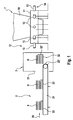
- FIG. 1 An embodiment of a slip-on device according to the invention is embedded in a filling system, as in Fig. 1 is shown schematically. It includes a filling machine 1, a supply device 2 for bundles of stacked valve bags and a slip-3.
- the filling machine 1 is only partially shown with a lower end of a storage bunker 10 for flowable material to be packaged, for example cement.
- a filling star 11 is arranged at the lower end of the storage bunker 10. This has a plurality of radially outwardly facing filling tubes 13. In the illustrated embodiment, the filling star 11 rotates about the stationary part with the storage bunker 10 of the filling machine 1, so that different stations are formed.
- a Aufsteckstation 12 facing the slip-on device 3 an isolated valve bag is attached to the filling tube 13 in each case.
- the filling star 11 continues to rotate, during which the valve bag is filled via the filling tube 13 until it finally reaches a filling weight and is removed from the filling tube 13 at an unloading station 14, after which the filling tube 13 continues to rotate again until it is sectioned relative to the attachment device. and the process begins again.
- the feeder 2 serves to feed bundles 9 stacked valve sacks 90. It comprises a conveyor belt 21 (in Fig. 1 only partially shown), which transports the bundle 9 through an input portal 31 to the slip-on device 3 from a feed point, not shown.
- the conveyor belt 21 is divided into a plurality of compartments 22, on each of which a bundle 9 comes to rest.
- the respective last compartment 22 ' is emptied, in which the bundle 9' located therein is transported onto the storage table 32 immediately following in the direction of travel of the strip 20.
- the storage table 32 may be facing away from the conveyor belt 21 at its End have a directional edge 32 ', along which the bundle 9' is automatically aligned by the feeding device 2.
- the separating device 4 serves to separate each of the topmost sack 90 from the bundle 9, in which it receives it, aligns it and moves the aligned sack in the attachment station 12 onto the filling tube 13.
- the slip-on device 3 comprises as main components a separating device 4, a transport device 5 as well as an alignment device 6 and a control 8.
- the separating device 4 decreases from the bundle 9 'lying on the delivery table 32 to the respective valve bag 90 which is located at the top.
- it has a lifting gripper 41, which between a receiving position (in Fig. 2a shown with solid lines) and a dispensing position (shown with dashed lines) is movable. In the illustrated embodiment, this is a pivoting movement about a pivot axis 43, but also any other type of movement (translational or combined translational / rotary) may be provided.
- the lifting gripper 41 has at its free end a receiving means, which is formed in the illustrated embodiment as suction cups 42.
- the uppermost valve bag 90 can be taken in several places, the lifting gripper 41 pivots about its axis 43 and thus transferred the valve bag 90 in a suspended position and finally transfers it to the transport device 5. Further, a sack bottom lifter (not shown) is expediently provided, the at Separating the uppermost sack 90 in support of lifting the sack bottom.
- the alignment is carried out according to the invention only after the separation, namely in the alignment station 6.
- the isolated valve sacks 90 are guided over the supply device 5 (see Fig. 2b ).
- the transport device 5 itself is designed in a manner known per se, namely with a horizontally moving conveyor belt 51 and a bar pressed against it with rollers as guide 50.
- the conveyor belt 51 which is usually designed as a driven V-ribbed belt, has a friction-increasing coating on its rear side , thanks to which the pressed from the guide 50 against the ribs valve sacks 90 are transported in the conveying direction 59.
- the separating device 4 is arranged (in Fig. 2b not shown).
- the alignment device 6 is arranged. It comprises two grippers 61, 61 'with shears 60, which are height-displaceable via a respective linear guide 62, 62'.
- an electric actuator 63, 63 ' is provided in each case. This can be carried out in a conventional manner as a spindle drive, along which the grippers 61, 61 'are guided in height movable.
- a second linear guide 64 is provided. It is arranged perpendicular to the linear guide 62.
- a drive device 65 which is preferably designed as a pneumatic drive.
- the gripper 61 can be moved away from the other gripper 61 'or moved back to it in the return stroke, whereby a spreading movement between the grippers 61, 61' is effected.
- the grippers 61, 61 ' are pivotally mounted in the horizontal about a pivot axis 66. It should be noted that the grippers 61, 61' by means of their respective associated actuator 63, 63 'can be moved individually in height. As a result, an alignment can be achieved even with an oblique position of the upper edge of the bag 90.
- a height sensor 82, 82 ' which are designed as a light barrier and each of the linear guides 62, 62' are assigned. They are connected to the control device 8, which in turn controls the actuators 63, 63 '. Furthermore, the control device 8 controls the pneumatic drive 65. Thus, it operates the alignment device 6 in the following manner.
- the reference name Fig. 4 describe the gripper 61, 61 'in an upper position (home position) waiting for the arrival of the bag 90 at the end of the transport device 5.
- the bag 90 moves in the transport device 5 in the intermediate position for receiving by the alignment device 6 (Phase Ia) , wherein the detection of this position is detected by a sensor 80 and reported to the control device 8 (phase Ib). Subsequently, by means of the actuators 63, 63 ', the grippers 61, 61' are moved downwards (phase IIa). By means of the sensors 82, 82 ', the reaching of the upper bag edge the valve bag 90 detected and reported to the controller 8 (Phase IIb). The controller 8 gives the signal to close the grippers 61, 61 'and the guide 50 opens (phase III).
- the spreading drive 65 is actuated, whereby the gripper 61 is moved away from the gripper 61 '(phase IVb).
- the bag is streamlined and smoothed.
- the valve bag 90 is aligned with it and can be spent on the filling tube 13.
- the guide 50 is closed again around the now aligned valve bag 90 (phase V).
- the bag now held in the correct position in the transport device 5 is transported further in the direction of the filling star 11 until a valve opening station 7 is reached.
- the valve bag 90 is accelerated by the control device 8 in time as the filling tube 13 advances past the transporting device 5 (phase VII) so that it is shot onto the filling tube 13 exactly.
- FIG. 5 An alternative method is in Fig. 5 shown. The differences are explained below. It is envisaged that the grippers 61, 61 'not wait in their upper position, but in their lower position in the open position (home position) on the arrival of the valve bag 90; The steps IIa and IIb concerning the method of the grippers 61, 61 'downwards until they reach the sack edge are eliminated. This will be after Step IV concerning the raising of the grippers 61, 61 ', an additional step IVc inserted, the grippers 61, 61' so far go up until the upper bag edge of the valve bag 90 has reached a defined position. This is preferably done individually for each of the two grippers 61, 61 '.
- the valve bag is according to the method in a defined position, regardless of the relative positioning of the valve bag 90 to the grippers 61, 61 'when receiving the valve bag 90.
- the phases V and VI are completed as described above.
- starting position starting position
- phase IIa refolded phase IIa
- phase II is omitted as a separate step, since it is carried out parallel to the transport of the bag (in phase VII).
- One step in the cycle is thus saved, which reduces the cycle time accordingly.
- the clock frequency can thus be further increased.
Landscapes
- Engineering & Computer Science (AREA)
- Mechanical Engineering (AREA)
- Supplying Of Containers To The Packaging Station (AREA)
- Auxiliary Devices For And Details Of Packaging Control (AREA)
Priority Applications (4)
| Application Number | Priority Date | Filing Date | Title |
|---|---|---|---|
| EP09005944A EP2246264B1 (de) | 2009-04-29 | 2009-04-29 | Aufsteckvorrichtung und Aufsteckverfahren für Ventilsäcke |
| ES09005944T ES2375328T3 (es) | 2009-04-29 | 2009-04-29 | Dispositivo de acoplamiento y procedimiento de acoplamiento para sacos con válvula. |
| AT09005944T ATE535451T1 (de) | 2009-04-29 | 2009-04-29 | Aufsteckvorrichtung und aufsteckverfahren für ventilsäcke |
| CN201010169282.XA CN101875407B (zh) | 2009-04-29 | 2010-04-29 | 用于阀袋的套装装置 |
Applications Claiming Priority (1)
| Application Number | Priority Date | Filing Date | Title |
|---|---|---|---|
| EP09005944A EP2246264B1 (de) | 2009-04-29 | 2009-04-29 | Aufsteckvorrichtung und Aufsteckverfahren für Ventilsäcke |
Publications (2)
| Publication Number | Publication Date |
|---|---|
| EP2246264A1 EP2246264A1 (de) | 2010-11-03 |
| EP2246264B1 true EP2246264B1 (de) | 2011-11-30 |
Family
ID=41110993
Family Applications (1)
| Application Number | Title | Priority Date | Filing Date |
|---|---|---|---|
| EP09005944A Not-in-force EP2246264B1 (de) | 2009-04-29 | 2009-04-29 | Aufsteckvorrichtung und Aufsteckverfahren für Ventilsäcke |
Country Status (4)
| Country | Link |
|---|---|
| EP (1) | EP2246264B1 (zh) |
| CN (1) | CN101875407B (zh) |
| AT (1) | ATE535451T1 (zh) |
| ES (1) | ES2375328T3 (zh) |
Families Citing this family (7)
| Publication number | Priority date | Publication date | Assignee | Title |
|---|---|---|---|---|
| DE102010051721A1 (de) * | 2010-11-20 | 2012-05-24 | Haver & Boecker Ohg | Vorrichtung und Verfahren zum Aufstecken von Säcken |
| DE102011119041A1 (de) * | 2011-11-22 | 2013-05-23 | Focke & Co. (Gmbh & Co. Kg) | Verfahren und Vorrichtung zum Handhaben von in Bündeln zusammengefassten Beuteln |
| JP5971041B2 (ja) * | 2011-11-25 | 2016-08-17 | 株式会社リコー | 情報処理装置、システム、情報処理方法、プログラム、記憶媒体 |
| US9815580B2 (en) | 2012-02-20 | 2017-11-14 | Bühler AG | Apparatus and method for packing bulk material into a container |
| CN103803102B (zh) * | 2013-11-15 | 2016-01-20 | 济南鲁新新型建材股份有限公司 | 一种自动水泥装袋设备 |
| ES2537852B1 (es) * | 2013-12-11 | 2015-11-12 | Payper, S.A. | Dispositivo nivelador de sacos |
| DE102015222303A1 (de) * | 2015-11-12 | 2017-05-18 | Claudius Peters Projects Gmbh | Sackaufsteckvorrichtung |
Family Cites Families (11)
| Publication number | Priority date | Publication date | Assignee | Title |
|---|---|---|---|---|
| US3522691A (en) * | 1968-11-12 | 1970-08-04 | L D Adcox | Machine for applying valve sack on filling machine spout |
| US3691715A (en) * | 1970-09-28 | 1972-09-19 | St Regis Paper Co | Valve bag applicator machine |
| US3715858A (en) * | 1971-09-01 | 1973-02-13 | Cherry Burrell Corp | Valve bag placer |
| US4548243A (en) * | 1983-11-04 | 1985-10-22 | General Portland, Inc. | Apparatus for automatically placing bags |
| DE3535941A1 (de) | 1984-10-27 | 1987-04-23 | Haver & Boecker | Vorrichtung zum aufstecken von zu fuellenden ventilsaecken auf den oder die fuellstutzen einer packmaschine |
| DE4015599C2 (de) * | 1990-05-15 | 1994-03-10 | Fraunhofer Ges Forschung | Greifer zum Öffnen von Ventilsäcken |
| DE4211089C2 (de) * | 1992-04-03 | 1997-08-07 | Haver & Boecker | Vorrichtung zur Vereinzelung von gestapelten Ventilsäcken und zum Aufstecken der Ventilsäcke auf den oder die Füllstutzen einer Ventilsackfüllmaschine |
| DE69600953T2 (de) * | 1995-06-30 | 1999-05-12 | Sigma Coatings B.V., Uithoorn | Automatische Ventilsack-Füllmaschine |
| DK174262B1 (da) * | 1998-04-21 | 2002-10-21 | Schur Packaging Systems As | Fremgangsmåde og anlæg til pakning af emner i folieposer, apparat til udøvelse af fremgangsmåden samt emballageemne til anvendelse ved fremgangsmåden i apparatet |
| DE20318956U1 (de) | 2003-12-06 | 2004-02-19 | Haver & Boecker | Vorrichtung zum Aufstecken von Ventilsäcken auf die Füllrohre einer Füllmaschine |
| US20080256905A1 (en) * | 2007-04-23 | 2008-10-23 | Michael Graf | Valve bag placing system and method |
-
2009
- 2009-04-29 EP EP09005944A patent/EP2246264B1/de not_active Not-in-force
- 2009-04-29 AT AT09005944T patent/ATE535451T1/de active
- 2009-04-29 ES ES09005944T patent/ES2375328T3/es active Active
-
2010
- 2010-04-29 CN CN201010169282.XA patent/CN101875407B/zh not_active Expired - Fee Related
Also Published As
| Publication number | Publication date |
|---|---|
| CN101875407A (zh) | 2010-11-03 |
| ATE535451T1 (de) | 2011-12-15 |
| CN101875407B (zh) | 2015-11-25 |
| EP2246264A1 (de) | 2010-11-03 |
| ES2375328T3 (es) | 2012-02-28 |
Similar Documents
| Publication | Publication Date | Title |
|---|---|---|
| EP2246264B1 (de) | Aufsteckvorrichtung und Aufsteckverfahren für Ventilsäcke | |
| DE1610467C3 (de) | Verfahren und Vorrichtung zum Aufsetzen des Schiebers und der oberen Endglieder auf vorkonfektionierte gekuppelte Reißverschlüsse | |
| DE3884944T2 (de) | Verpackungsvorrichtung für den Einsatz von schlauchförmigem Hüllmaterial. | |
| EP0380905B1 (de) | Einrichtung zum Zuführen vereinzelter Säcke | |
| EP3357816A1 (de) | Vorrichtung und verfahren zum transportieren und befüllen von säcken | |
| DE102012015401B4 (de) | Schalenverschließmaschine | |
| EP3088310B1 (de) | Vorrichtung und verfahren zum ausrichten und greifen eines sacks | |
| DE102017206970A1 (de) | Vorrichtung und Verfahren zum Transport von Produkten insbesondere für Verpackungsmaschinen | |
| EP2818421A1 (de) | Schalenverschließmaschine mit Trayzuführung und Verfahren für eine Verpackungsanlage | |
| DE102004004893B3 (de) | Kuvertwendestation | |
| EP3898471A1 (de) | Transportanlage für behälter | |
| EP0059746A1 (de) | Vorrichtung zum stapeln von in einem schuppenstrom anfallenden flächigen erzeugnissen. | |
| EP1636097B1 (de) | Vorrichtung und verfahren zum bearbeiten von kontinuierlich auf trägerelementen bereitgestellten packungen | |
| EP2025631B1 (de) | Stapelzelle | |
| EP1312551B1 (de) | Vorrichtung zum Bestücken einer Ware mit einem Tragegriff | |
| DE2743899A1 (de) | Verfahren zum zufuehren von mit einem ventil versehenen saecken und vorrichtung fuer maschinen zum verpacken von pulverfoermigen stoffen | |
| EP2054861B1 (de) | Aufstellvorrichtung für leergutbehälter | |
| EP2678171B1 (de) | Füllstation und verfahren zum befüllen eines kuverts | |
| EP1555207B1 (de) | Vorrichtung zum Aufstecken von Ventilsäcken auf die Füllrohre einer Füllmaschine | |
| DE2000214A1 (de) | Vorrichtung zur Zufuehrung von Papiersaecken zu beispielsweise einer Verarbeitungsmaschine | |
| EP1079940B1 (de) | Vorrichtung zum einbringen von gestapelten kuverts in einen transportkasten | |
| EP2367745B1 (de) | Vorrichtung und verfahren zum transfer von flexiblen flachen gegenständen | |
| DE102018000512A1 (de) | Verfahren und Vorrichtung für das direkte Abfüllen von Säcken in Kartons | |
| EP3088311B1 (de) | Vorrichtung zum aufstecken von ventilsäcken | |
| DE102008007262A1 (de) | Verfahren und Vorrichtung zum Zuführen von Packungsmänteln zu einer Füllmaschine |
Legal Events
| Date | Code | Title | Description |
|---|---|---|---|
| PUAI | Public reference made under article 153(3) epc to a published international application that has entered the european phase |
Free format text: ORIGINAL CODE: 0009012 |
|
| AK | Designated contracting states |
Kind code of ref document: A1 Designated state(s): AT BE BG CH CY CZ DE DK EE ES FI FR GB GR HR HU IE IS IT LI LT LU LV MC MK MT NL NO PL PT RO SE SI SK TR |
|
| AX | Request for extension of the european patent |
Extension state: AL BA RS |
|
| RAP1 | Party data changed (applicant data changed or rights of an application transferred) |
Owner name: CLAUDIUS PETERS PROJECTS GMBH |
|
| 17P | Request for examination filed |
Effective date: 20110503 |
|
| GRAP | Despatch of communication of intention to grant a patent |
Free format text: ORIGINAL CODE: EPIDOSNIGR1 |
|
| GRAS | Grant fee paid |
Free format text: ORIGINAL CODE: EPIDOSNIGR3 |
|
| GRAA | (expected) grant |
Free format text: ORIGINAL CODE: 0009210 |
|
| AK | Designated contracting states |
Kind code of ref document: B1 Designated state(s): AT BE BG CH CY CZ DE DK EE ES FI FR GB GR HR HU IE IS IT LI LT LU LV MC MK MT NL NO PL PT RO SE SI SK TR |
|
| REG | Reference to a national code |
Ref country code: CH Ref legal event code: EP Ref country code: GB Ref legal event code: FG4D Free format text: NOT ENGLISH |
|
| REG | Reference to a national code |
Ref country code: IE Ref legal event code: FG4D Free format text: LANGUAGE OF EP DOCUMENT: GERMAN |
|
| REG | Reference to a national code |
Ref country code: ES Ref legal event code: FG2A Ref document number: 2375328 Country of ref document: ES Kind code of ref document: T3 Effective date: 20120228 |
|
| REG | Reference to a national code |
Ref country code: DE Ref legal event code: R096 Ref document number: 502009002043 Country of ref document: DE Effective date: 20120301 |
|
| REG | Reference to a national code |
Ref country code: NL Ref legal event code: VDEP Effective date: 20111130 |
|
| LTIE | Lt: invalidation of european patent or patent extension |
Effective date: 20111130 |
|
| PG25 | Lapsed in a contracting state [announced via postgrant information from national office to epo] |
Ref country code: LT Free format text: LAPSE BECAUSE OF FAILURE TO SUBMIT A TRANSLATION OF THE DESCRIPTION OR TO PAY THE FEE WITHIN THE PRESCRIBED TIME-LIMIT Effective date: 20111130 Ref country code: NO Free format text: LAPSE BECAUSE OF FAILURE TO SUBMIT A TRANSLATION OF THE DESCRIPTION OR TO PAY THE FEE WITHIN THE PRESCRIBED TIME-LIMIT Effective date: 20120229 Ref country code: IS Free format text: LAPSE BECAUSE OF FAILURE TO SUBMIT A TRANSLATION OF THE DESCRIPTION OR TO PAY THE FEE WITHIN THE PRESCRIBED TIME-LIMIT Effective date: 20120330 |
|
| PG25 | Lapsed in a contracting state [announced via postgrant information from national office to epo] |
Ref country code: SI Free format text: LAPSE BECAUSE OF FAILURE TO SUBMIT A TRANSLATION OF THE DESCRIPTION OR TO PAY THE FEE WITHIN THE PRESCRIBED TIME-LIMIT Effective date: 20111130 Ref country code: GR Free format text: LAPSE BECAUSE OF FAILURE TO SUBMIT A TRANSLATION OF THE DESCRIPTION OR TO PAY THE FEE WITHIN THE PRESCRIBED TIME-LIMIT Effective date: 20120301 Ref country code: HR Free format text: LAPSE BECAUSE OF FAILURE TO SUBMIT A TRANSLATION OF THE DESCRIPTION OR TO PAY THE FEE WITHIN THE PRESCRIBED TIME-LIMIT Effective date: 20111130 Ref country code: PT Free format text: LAPSE BECAUSE OF FAILURE TO SUBMIT A TRANSLATION OF THE DESCRIPTION OR TO PAY THE FEE WITHIN THE PRESCRIBED TIME-LIMIT Effective date: 20120330 Ref country code: LV Free format text: LAPSE BECAUSE OF FAILURE TO SUBMIT A TRANSLATION OF THE DESCRIPTION OR TO PAY THE FEE WITHIN THE PRESCRIBED TIME-LIMIT Effective date: 20111130 Ref country code: NL Free format text: LAPSE BECAUSE OF FAILURE TO SUBMIT A TRANSLATION OF THE DESCRIPTION OR TO PAY THE FEE WITHIN THE PRESCRIBED TIME-LIMIT Effective date: 20111130 Ref country code: SE Free format text: LAPSE BECAUSE OF FAILURE TO SUBMIT A TRANSLATION OF THE DESCRIPTION OR TO PAY THE FEE WITHIN THE PRESCRIBED TIME-LIMIT Effective date: 20111130 |
|
| REG | Reference to a national code |
Ref country code: IE Ref legal event code: FD4D |
|
| PG25 | Lapsed in a contracting state [announced via postgrant information from national office to epo] |
Ref country code: CY Free format text: LAPSE BECAUSE OF FAILURE TO SUBMIT A TRANSLATION OF THE DESCRIPTION OR TO PAY THE FEE WITHIN THE PRESCRIBED TIME-LIMIT Effective date: 20111130 |
|
| PG25 | Lapsed in a contracting state [announced via postgrant information from national office to epo] |
Ref country code: EE Free format text: LAPSE BECAUSE OF FAILURE TO SUBMIT A TRANSLATION OF THE DESCRIPTION OR TO PAY THE FEE WITHIN THE PRESCRIBED TIME-LIMIT Effective date: 20111130 Ref country code: BG Free format text: LAPSE BECAUSE OF FAILURE TO SUBMIT A TRANSLATION OF THE DESCRIPTION OR TO PAY THE FEE WITHIN THE PRESCRIBED TIME-LIMIT Effective date: 20120229 Ref country code: DK Free format text: LAPSE BECAUSE OF FAILURE TO SUBMIT A TRANSLATION OF THE DESCRIPTION OR TO PAY THE FEE WITHIN THE PRESCRIBED TIME-LIMIT Effective date: 20111130 Ref country code: SK Free format text: LAPSE BECAUSE OF FAILURE TO SUBMIT A TRANSLATION OF THE DESCRIPTION OR TO PAY THE FEE WITHIN THE PRESCRIBED TIME-LIMIT Effective date: 20111130 Ref country code: IE Free format text: LAPSE BECAUSE OF FAILURE TO SUBMIT A TRANSLATION OF THE DESCRIPTION OR TO PAY THE FEE WITHIN THE PRESCRIBED TIME-LIMIT Effective date: 20111130 Ref country code: CZ Free format text: LAPSE BECAUSE OF FAILURE TO SUBMIT A TRANSLATION OF THE DESCRIPTION OR TO PAY THE FEE WITHIN THE PRESCRIBED TIME-LIMIT Effective date: 20111130 |
|
| PG25 | Lapsed in a contracting state [announced via postgrant information from national office to epo] |
Ref country code: PL Free format text: LAPSE BECAUSE OF FAILURE TO SUBMIT A TRANSLATION OF THE DESCRIPTION OR TO PAY THE FEE WITHIN THE PRESCRIBED TIME-LIMIT Effective date: 20111130 Ref country code: RO Free format text: LAPSE BECAUSE OF FAILURE TO SUBMIT A TRANSLATION OF THE DESCRIPTION OR TO PAY THE FEE WITHIN THE PRESCRIBED TIME-LIMIT Effective date: 20111130 |
|
| PGFP | Annual fee paid to national office [announced via postgrant information from national office to epo] |
Ref country code: FR Payment date: 20120511 Year of fee payment: 4 |
|
| PLBE | No opposition filed within time limit |
Free format text: ORIGINAL CODE: 0009261 |
|
| STAA | Information on the status of an ep patent application or granted ep patent |
Free format text: STATUS: NO OPPOSITION FILED WITHIN TIME LIMIT |
|
| BERE | Be: lapsed |
Owner name: CLAUDIUS PETERS PROJECTS G.M.B.H. Effective date: 20120430 |
|
| 26N | No opposition filed |
Effective date: 20120831 |
|
| PG25 | Lapsed in a contracting state [announced via postgrant information from national office to epo] |
Ref country code: MC Free format text: LAPSE BECAUSE OF NON-PAYMENT OF DUE FEES Effective date: 20120430 |
|
| REG | Reference to a national code |
Ref country code: DE Ref legal event code: R097 Ref document number: 502009002043 Country of ref document: DE Effective date: 20120831 |
|
| PG25 | Lapsed in a contracting state [announced via postgrant information from national office to epo] |
Ref country code: BE Free format text: LAPSE BECAUSE OF NON-PAYMENT OF DUE FEES Effective date: 20120430 |
|
| PG25 | Lapsed in a contracting state [announced via postgrant information from national office to epo] |
Ref country code: MK Free format text: LAPSE BECAUSE OF FAILURE TO SUBMIT A TRANSLATION OF THE DESCRIPTION OR TO PAY THE FEE WITHIN THE PRESCRIBED TIME-LIMIT Effective date: 20111130 |
|
| PG25 | Lapsed in a contracting state [announced via postgrant information from national office to epo] |
Ref country code: FI Free format text: LAPSE BECAUSE OF FAILURE TO SUBMIT A TRANSLATION OF THE DESCRIPTION OR TO PAY THE FEE WITHIN THE PRESCRIBED TIME-LIMIT Effective date: 20111130 |
|
| PG25 | Lapsed in a contracting state [announced via postgrant information from national office to epo] |
Ref country code: MT Free format text: LAPSE BECAUSE OF FAILURE TO SUBMIT A TRANSLATION OF THE DESCRIPTION OR TO PAY THE FEE WITHIN THE PRESCRIBED TIME-LIMIT Effective date: 20111130 |
|
| REG | Reference to a national code |
Ref country code: CH Ref legal event code: PL |
|
| GBPC | Gb: european patent ceased through non-payment of renewal fee |
Effective date: 20130429 |
|
| PG25 | Lapsed in a contracting state [announced via postgrant information from national office to epo] |
Ref country code: LI Free format text: LAPSE BECAUSE OF NON-PAYMENT OF DUE FEES Effective date: 20130430 Ref country code: GB Free format text: LAPSE BECAUSE OF NON-PAYMENT OF DUE FEES Effective date: 20130429 Ref country code: CH Free format text: LAPSE BECAUSE OF NON-PAYMENT OF DUE FEES Effective date: 20130430 |
|
| REG | Reference to a national code |
Ref country code: FR Ref legal event code: ST Effective date: 20131231 |
|
| PG25 | Lapsed in a contracting state [announced via postgrant information from national office to epo] |
Ref country code: FR Free format text: LAPSE BECAUSE OF NON-PAYMENT OF DUE FEES Effective date: 20130430 |
|
| PG25 | Lapsed in a contracting state [announced via postgrant information from national office to epo] |
Ref country code: TR Free format text: LAPSE BECAUSE OF FAILURE TO SUBMIT A TRANSLATION OF THE DESCRIPTION OR TO PAY THE FEE WITHIN THE PRESCRIBED TIME-LIMIT Effective date: 20111130 |
|
| PG25 | Lapsed in a contracting state [announced via postgrant information from national office to epo] |
Ref country code: LU Free format text: LAPSE BECAUSE OF NON-PAYMENT OF DUE FEES Effective date: 20120429 |
|
| PG25 | Lapsed in a contracting state [announced via postgrant information from national office to epo] |
Ref country code: HU Free format text: LAPSE BECAUSE OF FAILURE TO SUBMIT A TRANSLATION OF THE DESCRIPTION OR TO PAY THE FEE WITHIN THE PRESCRIBED TIME-LIMIT Effective date: 20090429 |
|
| PGFP | Annual fee paid to national office [announced via postgrant information from national office to epo] |
Ref country code: IT Payment date: 20140424 Year of fee payment: 6 Ref country code: ES Payment date: 20140417 Year of fee payment: 6 |
|
| REG | Reference to a national code |
Ref country code: AT Ref legal event code: MM01 Ref document number: 535451 Country of ref document: AT Kind code of ref document: T Effective date: 20140429 |
|
| PG25 | Lapsed in a contracting state [announced via postgrant information from national office to epo] |
Ref country code: AT Free format text: LAPSE BECAUSE OF NON-PAYMENT OF DUE FEES Effective date: 20140429 |
|
| PG25 | Lapsed in a contracting state [announced via postgrant information from national office to epo] |
Ref country code: IT Free format text: LAPSE BECAUSE OF NON-PAYMENT OF DUE FEES Effective date: 20150429 |
|
| REG | Reference to a national code |
Ref country code: ES Ref legal event code: FD2A Effective date: 20170102 |
|
| PG25 | Lapsed in a contracting state [announced via postgrant information from national office to epo] |
Ref country code: ES Free format text: LAPSE BECAUSE OF NON-PAYMENT OF DUE FEES Effective date: 20150430 |
|
| PGFP | Annual fee paid to national office [announced via postgrant information from national office to epo] |
Ref country code: DE Payment date: 20170627 Year of fee payment: 9 |
|
| REG | Reference to a national code |
Ref country code: DE Ref legal event code: R119 Ref document number: 502009002043 Country of ref document: DE |
|
| PG25 | Lapsed in a contracting state [announced via postgrant information from national office to epo] |
Ref country code: DE Free format text: LAPSE BECAUSE OF NON-PAYMENT OF DUE FEES Effective date: 20181101 |