EP2244318B1 - Fermeture de bloc-batteries avec système de déclencheur d'amorçage thermique commandé - Google Patents
Fermeture de bloc-batteries avec système de déclencheur d'amorçage thermique commandé Download PDFInfo
- Publication number
- EP2244318B1 EP2244318B1 EP20100003915 EP10003915A EP2244318B1 EP 2244318 B1 EP2244318 B1 EP 2244318B1 EP 20100003915 EP20100003915 EP 20100003915 EP 10003915 A EP10003915 A EP 10003915A EP 2244318 B1 EP2244318 B1 EP 2244318B1
- Authority
- EP
- European Patent Office
- Prior art keywords
- battery pack
- enclosure
- wall
- comprised
- thermal runaway
- Prior art date
- Legal status (The legal status is an assumption and is not a legal conclusion. Google has not performed a legal analysis and makes no representation as to the accuracy of the status listed.)
- Active
Links
- 239000000463 material Substances 0.000 claims description 74
- 238000002844 melting Methods 0.000 claims description 24
- 230000008018 melting Effects 0.000 claims description 24
- 238000007789 sealing Methods 0.000 claims description 12
- 229910052751 metal Inorganic materials 0.000 claims description 10
- 239000002184 metal Substances 0.000 claims description 10
- 239000000919 ceramic Substances 0.000 claims description 6
- 239000000565 sealant Substances 0.000 claims description 6
- 239000007789 gas Substances 0.000 description 39
- 239000012212 insulator Substances 0.000 description 13
- 230000007246 mechanism Effects 0.000 description 13
- 238000013461 design Methods 0.000 description 12
- 238000009413 insulation Methods 0.000 description 11
- 230000001902 propagating effect Effects 0.000 description 8
- 239000002826 coolant Substances 0.000 description 6
- 239000000779 smoke Substances 0.000 description 6
- 238000013459 approach Methods 0.000 description 5
- 229910001416 lithium ion Inorganic materials 0.000 description 5
- 241000156302 Porcine hemagglutinating encephalomyelitis virus Species 0.000 description 4
- 238000002485 combustion reaction Methods 0.000 description 4
- 238000001816 cooling Methods 0.000 description 4
- 230000006378 damage Effects 0.000 description 4
- -1 etc.) Inorganic materials 0.000 description 4
- 230000004048 modification Effects 0.000 description 4
- 238000012986 modification Methods 0.000 description 4
- HBBGRARXTFLTSG-UHFFFAOYSA-N Lithium ion Chemical compound [Li+] HBBGRARXTFLTSG-UHFFFAOYSA-N 0.000 description 3
- 239000003063 flame retardant Substances 0.000 description 3
- 230000000977 initiatory effect Effects 0.000 description 3
- 238000004519 manufacturing process Methods 0.000 description 3
- 238000003860 storage Methods 0.000 description 3
- VYPSYNLAJGMNEJ-UHFFFAOYSA-N Silicium dioxide Chemical compound O=[Si]=O VYPSYNLAJGMNEJ-UHFFFAOYSA-N 0.000 description 2
- 229910000831 Steel Inorganic materials 0.000 description 2
- GWEVSGVZZGPLCZ-UHFFFAOYSA-N Titan oxide Chemical compound O=[Ti]=O GWEVSGVZZGPLCZ-UHFFFAOYSA-N 0.000 description 2
- 230000002159 abnormal effect Effects 0.000 description 2
- 229910052782 aluminium Inorganic materials 0.000 description 2
- XAGFODPZIPBFFR-UHFFFAOYSA-N aluminium Chemical compound [Al] XAGFODPZIPBFFR-UHFFFAOYSA-N 0.000 description 2
- 238000006243 chemical reaction Methods 0.000 description 2
- 230000008878 coupling Effects 0.000 description 2
- 238000010168 coupling process Methods 0.000 description 2
- 238000005859 coupling reaction Methods 0.000 description 2
- 238000009826 distribution Methods 0.000 description 2
- 230000000694 effects Effects 0.000 description 2
- 238000005516 engineering process Methods 0.000 description 2
- 239000000155 melt Substances 0.000 description 2
- 229910052759 nickel Inorganic materials 0.000 description 2
- PXHVJJICTQNCMI-UHFFFAOYSA-N nickel Substances [Ni] PXHVJJICTQNCMI-UHFFFAOYSA-N 0.000 description 2
- 239000010959 steel Substances 0.000 description 2
- OKTJSMMVPCPJKN-UHFFFAOYSA-N Carbon Chemical compound [C] OKTJSMMVPCPJKN-UHFFFAOYSA-N 0.000 description 1
- 229910045601 alloy Inorganic materials 0.000 description 1
- 239000000956 alloy Substances 0.000 description 1
- PNEYBMLMFCGWSK-UHFFFAOYSA-N aluminium oxide Inorganic materials [O-2].[O-2].[O-2].[Al+3].[Al+3] PNEYBMLMFCGWSK-UHFFFAOYSA-N 0.000 description 1
- OJIJEKBXJYRIBZ-UHFFFAOYSA-N cadmium nickel Chemical compound [Ni].[Cd] OJIJEKBXJYRIBZ-UHFFFAOYSA-N 0.000 description 1
- 229910052799 carbon Inorganic materials 0.000 description 1
- 239000002131 composite material Substances 0.000 description 1
- 239000004020 conductor Substances 0.000 description 1
- 230000007547 defect Effects 0.000 description 1
- 230000007613 environmental effect Effects 0.000 description 1
- 239000011152 fibreglass Substances 0.000 description 1
- 230000036541 health Effects 0.000 description 1
- 230000020169 heat generation Effects 0.000 description 1
- 238000010438 heat treatment Methods 0.000 description 1
- 229910052739 hydrogen Inorganic materials 0.000 description 1
- 239000001257 hydrogen Substances 0.000 description 1
- 230000002401 inhibitory effect Effects 0.000 description 1
- 239000011810 insulating material Substances 0.000 description 1
- 229910000625 lithium cobalt oxide Inorganic materials 0.000 description 1
- GELKBWJHTRAYNV-UHFFFAOYSA-K lithium iron phosphate Chemical compound [Li+].[Fe+2].[O-]P([O-])([O-])=O GELKBWJHTRAYNV-UHFFFAOYSA-K 0.000 description 1
- 229910021450 lithium metal oxide Inorganic materials 0.000 description 1
- BFZPBUKRYWOWDV-UHFFFAOYSA-N lithium;oxido(oxo)cobalt Chemical compound [Li+].[O-][Co]=O BFZPBUKRYWOWDV-UHFFFAOYSA-N 0.000 description 1
- 230000013011 mating Effects 0.000 description 1
- 229910052987 metal hydride Inorganic materials 0.000 description 1
- 150000002739 metals Chemical class 0.000 description 1
- 238000000034 method Methods 0.000 description 1
- QELJHCBNGDEXLD-UHFFFAOYSA-N nickel zinc Chemical compound [Ni].[Zn] QELJHCBNGDEXLD-UHFFFAOYSA-N 0.000 description 1
- 150000004767 nitrides Chemical class 0.000 description 1
- 238000010943 off-gassing Methods 0.000 description 1
- 238000012354 overpressurization Methods 0.000 description 1
- 230000037361 pathway Effects 0.000 description 1
- 239000004033 plastic Substances 0.000 description 1
- 229920003023 plastic Polymers 0.000 description 1
- 229920000642 polymer Polymers 0.000 description 1
- 230000008569 process Effects 0.000 description 1
- 229910021332 silicide Inorganic materials 0.000 description 1
- FVBUAEGBCNSCDD-UHFFFAOYSA-N silicide(4-) Chemical compound [Si-4] FVBUAEGBCNSCDD-UHFFFAOYSA-N 0.000 description 1
- 239000000377 silicon dioxide Substances 0.000 description 1
- BSWGGJHLVUUXTL-UHFFFAOYSA-N silver zinc Chemical compound [Zn].[Ag] BSWGGJHLVUUXTL-UHFFFAOYSA-N 0.000 description 1
- 229910000679 solder Inorganic materials 0.000 description 1
- 125000006850 spacer group Chemical group 0.000 description 1
- 238000013022 venting Methods 0.000 description 1
Images


Classifications
-
- H—ELECTRICITY
- H01—ELECTRIC ELEMENTS
- H01M—PROCESSES OR MEANS, e.g. BATTERIES, FOR THE DIRECT CONVERSION OF CHEMICAL ENERGY INTO ELECTRICAL ENERGY
- H01M10/00—Secondary cells; Manufacture thereof
- H01M10/60—Heating or cooling; Temperature control
- H01M10/65—Means for temperature control structurally associated with the cells
- H01M10/658—Means for temperature control structurally associated with the cells by thermal insulation or shielding
-
- B—PERFORMING OPERATIONS; TRANSPORTING
- B60—VEHICLES IN GENERAL
- B60K—ARRANGEMENT OR MOUNTING OF PROPULSION UNITS OR OF TRANSMISSIONS IN VEHICLES; ARRANGEMENT OR MOUNTING OF PLURAL DIVERSE PRIME-MOVERS IN VEHICLES; AUXILIARY DRIVES FOR VEHICLES; INSTRUMENTATION OR DASHBOARDS FOR VEHICLES; ARRANGEMENTS IN CONNECTION WITH COOLING, AIR INTAKE, GAS EXHAUST OR FUEL SUPPLY OF PROPULSION UNITS IN VEHICLES
- B60K1/00—Arrangement or mounting of electrical propulsion units
- B60K1/04—Arrangement or mounting of electrical propulsion units of the electric storage means for propulsion
-
- B—PERFORMING OPERATIONS; TRANSPORTING
- B60—VEHICLES IN GENERAL
- B60L—PROPULSION OF ELECTRICALLY-PROPELLED VEHICLES; SUPPLYING ELECTRIC POWER FOR AUXILIARY EQUIPMENT OF ELECTRICALLY-PROPELLED VEHICLES; ELECTRODYNAMIC BRAKE SYSTEMS FOR VEHICLES IN GENERAL; MAGNETIC SUSPENSION OR LEVITATION FOR VEHICLES; MONITORING OPERATING VARIABLES OF ELECTRICALLY-PROPELLED VEHICLES; ELECTRIC SAFETY DEVICES FOR ELECTRICALLY-PROPELLED VEHICLES
- B60L50/00—Electric propulsion with power supplied within the vehicle
- B60L50/50—Electric propulsion with power supplied within the vehicle using propulsion power supplied by batteries or fuel cells
- B60L50/60—Electric propulsion with power supplied within the vehicle using propulsion power supplied by batteries or fuel cells using power supplied by batteries
- B60L50/64—Constructional details of batteries specially adapted for electric vehicles
-
- H—ELECTRICITY
- H01—ELECTRIC ELEMENTS
- H01M—PROCESSES OR MEANS, e.g. BATTERIES, FOR THE DIRECT CONVERSION OF CHEMICAL ENERGY INTO ELECTRICAL ENERGY
- H01M10/00—Secondary cells; Manufacture thereof
- H01M10/60—Heating or cooling; Temperature control
- H01M10/62—Heating or cooling; Temperature control specially adapted for specific applications
- H01M10/625—Vehicles
-
- H—ELECTRICITY
- H01—ELECTRIC ELEMENTS
- H01M—PROCESSES OR MEANS, e.g. BATTERIES, FOR THE DIRECT CONVERSION OF CHEMICAL ENERGY INTO ELECTRICAL ENERGY
- H01M10/00—Secondary cells; Manufacture thereof
- H01M10/60—Heating or cooling; Temperature control
- H01M10/65—Means for temperature control structurally associated with the cells
- H01M10/653—Means for temperature control structurally associated with the cells characterised by electrically insulating or thermally conductive materials
-
- H—ELECTRICITY
- H01—ELECTRIC ELEMENTS
- H01M—PROCESSES OR MEANS, e.g. BATTERIES, FOR THE DIRECT CONVERSION OF CHEMICAL ENERGY INTO ELECTRICAL ENERGY
- H01M50/00—Constructional details or processes of manufacture of the non-active parts of electrochemical cells other than fuel cells, e.g. hybrid cells
- H01M50/10—Primary casings; Jackets or wrappings
- H01M50/183—Sealing members
- H01M50/186—Sealing members characterised by the disposition of the sealing members
-
- H—ELECTRICITY
- H01—ELECTRIC ELEMENTS
- H01M—PROCESSES OR MEANS, e.g. BATTERIES, FOR THE DIRECT CONVERSION OF CHEMICAL ENERGY INTO ELECTRICAL ENERGY
- H01M50/00—Constructional details or processes of manufacture of the non-active parts of electrochemical cells other than fuel cells, e.g. hybrid cells
- H01M50/20—Mountings; Secondary casings or frames; Racks, modules or packs; Suspension devices; Shock absorbers; Transport or carrying devices; Holders
- H01M50/233—Mountings; Secondary casings or frames; Racks, modules or packs; Suspension devices; Shock absorbers; Transport or carrying devices; Holders characterised by physical properties of casings or racks, e.g. dimensions
- H01M50/24—Mountings; Secondary casings or frames; Racks, modules or packs; Suspension devices; Shock absorbers; Transport or carrying devices; Holders characterised by physical properties of casings or racks, e.g. dimensions adapted for protecting batteries from their environment, e.g. from corrosion
-
- H—ELECTRICITY
- H01—ELECTRIC ELEMENTS
- H01M—PROCESSES OR MEANS, e.g. BATTERIES, FOR THE DIRECT CONVERSION OF CHEMICAL ENERGY INTO ELECTRICAL ENERGY
- H01M50/00—Constructional details or processes of manufacture of the non-active parts of electrochemical cells other than fuel cells, e.g. hybrid cells
- H01M50/20—Mountings; Secondary casings or frames; Racks, modules or packs; Suspension devices; Shock absorbers; Transport or carrying devices; Holders
- H01M50/249—Mountings; Secondary casings or frames; Racks, modules or packs; Suspension devices; Shock absorbers; Transport or carrying devices; Holders specially adapted for aircraft or vehicles, e.g. cars or trains
-
- H—ELECTRICITY
- H01—ELECTRIC ELEMENTS
- H01M—PROCESSES OR MEANS, e.g. BATTERIES, FOR THE DIRECT CONVERSION OF CHEMICAL ENERGY INTO ELECTRICAL ENERGY
- H01M50/00—Constructional details or processes of manufacture of the non-active parts of electrochemical cells other than fuel cells, e.g. hybrid cells
- H01M50/30—Arrangements for facilitating escape of gases
- H01M50/342—Non-re-sealable arrangements
-
- H—ELECTRICITY
- H01—ELECTRIC ELEMENTS
- H01M—PROCESSES OR MEANS, e.g. BATTERIES, FOR THE DIRECT CONVERSION OF CHEMICAL ENERGY INTO ELECTRICAL ENERGY
- H01M50/00—Constructional details or processes of manufacture of the non-active parts of electrochemical cells other than fuel cells, e.g. hybrid cells
- H01M50/30—Arrangements for facilitating escape of gases
- H01M50/35—Gas exhaust passages comprising elongated, tortuous or labyrinth-shaped exhaust passages
- H01M50/367—Internal gas exhaust passages forming part of the battery cover or case; Double cover vent systems
-
- B—PERFORMING OPERATIONS; TRANSPORTING
- B60—VEHICLES IN GENERAL
- B60K—ARRANGEMENT OR MOUNTING OF PROPULSION UNITS OR OF TRANSMISSIONS IN VEHICLES; ARRANGEMENT OR MOUNTING OF PLURAL DIVERSE PRIME-MOVERS IN VEHICLES; AUXILIARY DRIVES FOR VEHICLES; INSTRUMENTATION OR DASHBOARDS FOR VEHICLES; ARRANGEMENTS IN CONNECTION WITH COOLING, AIR INTAKE, GAS EXHAUST OR FUEL SUPPLY OF PROPULSION UNITS IN VEHICLES
- B60K1/00—Arrangement or mounting of electrical propulsion units
- B60K1/04—Arrangement or mounting of electrical propulsion units of the electric storage means for propulsion
- B60K2001/0405—Arrangement or mounting of electrical propulsion units of the electric storage means for propulsion characterised by their position
- B60K2001/0438—Arrangement under the floor
-
- H—ELECTRICITY
- H01—ELECTRIC ELEMENTS
- H01M—PROCESSES OR MEANS, e.g. BATTERIES, FOR THE DIRECT CONVERSION OF CHEMICAL ENERGY INTO ELECTRICAL ENERGY
- H01M2200/00—Safety devices for primary or secondary batteries
- H01M2200/10—Temperature sensitive devices
-
- H—ELECTRICITY
- H01—ELECTRIC ELEMENTS
- H01M—PROCESSES OR MEANS, e.g. BATTERIES, FOR THE DIRECT CONVERSION OF CHEMICAL ENERGY INTO ELECTRICAL ENERGY
- H01M50/00—Constructional details or processes of manufacture of the non-active parts of electrochemical cells other than fuel cells, e.g. hybrid cells
- H01M50/20—Mountings; Secondary casings or frames; Racks, modules or packs; Suspension devices; Shock absorbers; Transport or carrying devices; Holders
- H01M50/204—Racks, modules or packs for multiple batteries or multiple cells
- H01M50/207—Racks, modules or packs for multiple batteries or multiple cells characterised by their shape
- H01M50/213—Racks, modules or packs for multiple batteries or multiple cells characterised by their shape adapted for cells having curved cross-section, e.g. round or elliptic
-
- H—ELECTRICITY
- H01—ELECTRIC ELEMENTS
- H01M—PROCESSES OR MEANS, e.g. BATTERIES, FOR THE DIRECT CONVERSION OF CHEMICAL ENERGY INTO ELECTRICAL ENERGY
- H01M50/00—Constructional details or processes of manufacture of the non-active parts of electrochemical cells other than fuel cells, e.g. hybrid cells
- H01M50/20—Mountings; Secondary casings or frames; Racks, modules or packs; Suspension devices; Shock absorbers; Transport or carrying devices; Holders
- H01M50/218—Mountings; Secondary casings or frames; Racks, modules or packs; Suspension devices; Shock absorbers; Transport or carrying devices; Holders characterised by the material
- H01M50/22—Mountings; Secondary casings or frames; Racks, modules or packs; Suspension devices; Shock absorbers; Transport or carrying devices; Holders characterised by the material of the casings or racks
- H01M50/222—Inorganic material
- H01M50/224—Metals
-
- H—ELECTRICITY
- H01—ELECTRIC ELEMENTS
- H01M—PROCESSES OR MEANS, e.g. BATTERIES, FOR THE DIRECT CONVERSION OF CHEMICAL ENERGY INTO ELECTRICAL ENERGY
- H01M50/00—Constructional details or processes of manufacture of the non-active parts of electrochemical cells other than fuel cells, e.g. hybrid cells
- H01M50/20—Mountings; Secondary casings or frames; Racks, modules or packs; Suspension devices; Shock absorbers; Transport or carrying devices; Holders
- H01M50/271—Lids or covers for the racks or secondary casings
- H01M50/273—Lids or covers for the racks or secondary casings characterised by the material
- H01M50/276—Inorganic material
-
- H—ELECTRICITY
- H01—ELECTRIC ELEMENTS
- H01M—PROCESSES OR MEANS, e.g. BATTERIES, FOR THE DIRECT CONVERSION OF CHEMICAL ENERGY INTO ELECTRICAL ENERGY
- H01M50/00—Constructional details or processes of manufacture of the non-active parts of electrochemical cells other than fuel cells, e.g. hybrid cells
- H01M50/30—Arrangements for facilitating escape of gases
- H01M50/342—Non-re-sealable arrangements
- H01M50/3425—Non-re-sealable arrangements in the form of rupturable membranes or weakened parts, e.g. pierced with the aid of a sharp member
-
- Y—GENERAL TAGGING OF NEW TECHNOLOGICAL DEVELOPMENTS; GENERAL TAGGING OF CROSS-SECTIONAL TECHNOLOGIES SPANNING OVER SEVERAL SECTIONS OF THE IPC; TECHNICAL SUBJECTS COVERED BY FORMER USPC CROSS-REFERENCE ART COLLECTIONS [XRACs] AND DIGESTS
- Y02—TECHNOLOGIES OR APPLICATIONS FOR MITIGATION OR ADAPTATION AGAINST CLIMATE CHANGE
- Y02E—REDUCTION OF GREENHOUSE GAS [GHG] EMISSIONS, RELATED TO ENERGY GENERATION, TRANSMISSION OR DISTRIBUTION
- Y02E60/00—Enabling technologies; Technologies with a potential or indirect contribution to GHG emissions mitigation
- Y02E60/10—Energy storage using batteries
-
- Y—GENERAL TAGGING OF NEW TECHNOLOGICAL DEVELOPMENTS; GENERAL TAGGING OF CROSS-SECTIONAL TECHNOLOGIES SPANNING OVER SEVERAL SECTIONS OF THE IPC; TECHNICAL SUBJECTS COVERED BY FORMER USPC CROSS-REFERENCE ART COLLECTIONS [XRACs] AND DIGESTS
- Y02—TECHNOLOGIES OR APPLICATIONS FOR MITIGATION OR ADAPTATION AGAINST CLIMATE CHANGE
- Y02T—CLIMATE CHANGE MITIGATION TECHNOLOGIES RELATED TO TRANSPORTATION
- Y02T10/00—Road transport of goods or passengers
- Y02T10/60—Other road transportation technologies with climate change mitigation effect
- Y02T10/70—Energy storage systems for electromobility, e.g. batteries
Definitions
- the present invention relates generally to battery packs and, more particularly, to a system for controlling the release of thermal energy and hot gas from a battery pack undergoing thermal runaway.
- thermal runaway event a large amount of thermal energy is rapidly released, heating the entire cell up to a temperature of 850° C or more. Due to the increased temperature of the cell undergoing thermal runaway, the temperature of adjacent cells within the battery pack will also increase. If the temperature of these adjacent cells is allowed to increase unimpeded, they may also enter into a state of thermal runaway, leading to a cascading effect where the initiation of thermal runaway within a single cell propagates throughout the entire battery pack. As a result, power from the battery pack is interrupted and the system employing the battery pack is more likely to incur extensive collateral damage due to the scale of thermal runaway and the associated release of thermal energy.
- a number of approaches have been employed to either reduce the risk of thermal runaway, or reduce the risk of thermal runaway propagation. For example, by insulating the battery terminals and using specifically designed battery storage containers, the risk of shorting during storage and/or handling can be reduced. Another approach is to develop new cell chemistries and/or modify existing cell chemistries. Yet another approach, disclosed in co-pending U.S. Patent Applications Nos. 12/504,712 , 12/460,372 , 12/460,342 , 12/460,423 and 12/460,346 , is to provide additional shielding at the cell level, thus inhibiting the flow of thermal energy from the cell undergoing thermal runaway to adjacent cells. Still yet another approach, disclosed in co-pending U.S. Patent Application No. 12/545,146 , is to use a spacer assembly to maintain the position of the battery undergoing thermal runaway in its predetermined location within the battery pack, thereby helping to minimize the thermal effects on adjacent cells.
- a battery pack thermal management system is provided that is comprised of an enclosure failure port integrated into a wall of a battery pack enclosure, where the enclosure failure port remains closed during normal operation of the battery pack, and opens during a battery pack thermal runaway event, thereby providing a flow path for hot gas generated during the thermal runaway event to be exhausted out of the battery pack enclosure.
- the battery pack enclosure may be comprised of a material with a melting temperature greater than 800° C; comprised of a material with a melting temperature greater than 1000° C; comprised of a material that includes an outer layer and an inner ceramic layer, for example where the inner ceramic layer prevents the outer layer from melting during the battery pack thermal runaway event; and/or comprised of a material that includes an outer layer and an inner intumescent layer, for example where the inner intumescent layer prevents the outer layer from melting during the battery pack thermal runaway event.
- the battery pack enclosure may be comprised of first and second housing members with means to secure the two housing members together; and comprised of first and second housing members with means to secure the two housing members together and with a sealing gasket configured to be interposed between the sealing surfaces of the first and second housing members.
- the sealing gasket may be comprised of multiple portions, where a first portion is comprised of a first gasket material with a first melting temperature and a second portion is comprised of a second gasket material with a second melting temperature, where the second melting temperature is less than the first melting temperature, and where the enclosure failure port is comprised of the second portion of the sealing gasket.
- the enclosure failure port may be configured to open when the internal battery pack temperature exceeds a preset temperature and/or when the internal battery pack temperature exceeds a preset temperature and the internal battery pack pressure exceeds a preset pressure.
- the enclosure failure port may be comprised of a cover covering an enclosure port and attached to the enclosure using a sealant that fails during the battery pack thermal runaway event, thereby allowing the cover to detach from the wall; alternately, the enclosure failure port may be comprised of a region of the enclosure wall that is thinner than the surrounding wall such that it fails during the battery pack thermal runaway event; alternately, the enclosure failure port may be comprised of a region of the enclosure wall that is scored such that this region fails during the battery pack thermal runaway event; alternately, the enclosure failure port may be comprised of a cover covering an enclosure port, the cover having a lower melting point than the enclosure such that it fails when the temperature of the enclosure increases due to the battery thermal runaway event; alternately, the enclosure failure port may be comprised of a cover covering an enclosure port and attached to the
- the system also includes a heat resistant channel, such as an open or closed channel, that directs the flow of hot gas exhausted through the enclosure failure port during a thermal runaway event, for example directing the flow away from a vehicle passenger compartment.
- a heat resistant channel such as an open or closed channel
- the system also includes at least one layer of a thermal insulator positioned between the battery pack enclosure and a vehicle passenger compartment.
- the system also includes at least one layer of a fire retardant material (e.g., an intumescent material) positioned between the battery pack enclosure and a vehicle passenger compartment.
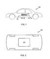
- Fig. 1 provides a side view of a battery pack mounted under a car
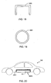
- Fig. 2 provides a bottom view of the battery pack of Fig. 1 ;
- Fig. 3 is a perspective view of a preferred embodiment of a battery pack enclosure
- Fig. 4 is a perspective view of a preferred embodiment of a battery pack enclosure utilizing a multi-section enclosure gasket
- Fig. 5 is a side view of a portion of a battery pack enclosure illustrating an embodiment of an enclosure failure mechanism
- Fig. 6 is a cross-sectional view of the enclosure failure mechanism shown in Fig. 5 ;
- Fig. 7 is a cross-sectional view of an alternate enclosure failure mechanism using a thinned enclosure wall
- Fig. 8 is a cross-sectional view of an alternate enclosure failure mechanism using a scored enclosure wall
- Fig. 9 is a side view of a portion of a battery pack enclosure illustrating an alternate embodiment of an enclosure failure mechanism
- Fig. 10 is a cross-sectional view of the enclosure failure mechanism shown in Fig. 9 ;
- Fig. 11 is a side view of a portion of a battery pack enclosure illustrating an alternate embodiment of an enclosure failure mechanism
- Fig. 12 is a cross-sectional view of the enclosure failure mechanism shown in Fig. 11 ;
- Fig. 13 illustrates a modification of the embodiment illustrated in Fig. 5 , the modification directing the flow of hot gas and material out of the exhaust port;
- Fig. 14 is a cross-sectional view of the enclosure failure mechanism shown in Fig. 13 ;
- Fig. 15 illustrates a modification of the embodiment illustrated in Fig. 7 , the modification directing the flow of hot gas and material out of the exhaust port;
- Fig. 16 illustrates an alternate view of the embodiment shown in Fig. 15 ;
- Fig. 17 illustrates an embodiment of the invention utilizing one or more heat resistant channels to direct the flow from the battery pack enclosure failure ports
- Fig. 18 is a cross-sectional view of an open channel for use with the embodiment illustrated in Fig. 17 ;
- Fig. 19 is a cross-sectional view of a closed channel for use with the embodiment illustrated in Fig. 17 ;
- Fig. 20 illustrates an embodiment utilizing thermal insulation to reduce the flow of thermal energy from the battery pack enclosure to adjacent vehicle regions
- Fig. 21 illustrates an embodiment utilizing a blower fan to force air around the battery pack enclosure.
- battery may be used interchangeably and may refer to any of a variety of different rechargeable cell chemistries and configurations including, but not limited to, lithium-ion (e.g., lithium iron phosphate, lithium cobalt oxide, other lithium metal oxides, etc.), lithium-ion polymer, nickel metal hydride, nickel cadmium, nickel hydrogen, nickel zinc, silver zinc, or other battery type/configuration.
- battery pack refers to multiple individual batteries contained within a single piece or multi-piece housing, the individual batteries electrically interconnected to achieve the desired voltage and capacity for a particular application.
- electric vehicle refers to either an all electric vehicle, also referred to as an EV, plug-in hybrid vehicles, also referred to as a PHEV, or a hybrid vehicle (HEV), a hybrid vehicle utilizing multiple propulsion sources one of which is an electric drive system.
- EV all electric vehicle
- plug-in hybrid vehicles also referred to as a PHEV
- HEV hybrid vehicle
- the rechargeable batteries used in an electric vehicle store a significant amount of energy.
- the amount of energy per cell and the total amount of energy stored per battery pack depends upon the type of cell and the number of cells within the pack.
- lithium-ion cells with an 18650 form factor store approximately 30 kJ of thermal energy when completely charged, and therefore a battery pack with 8000 cells stores up to approximately 240 MJ of thermal energy, depending upon the state of charge of the individual cells within the pack.
- a cell within such a battery pack undergoes thermal runaway, it releases its thermal energy, some of which is in the form of hot gas (e.g., approximately 5 liters of hot gas for a lithium-ion 18650 cell).
- Figs. 1 and 2 provide side and bottom views, respectively, of a car 100 with a battery pack 101 mounted underneath the car.
- the battery pack configuration shown in Figs. 1 and 2 is simply for illustration purposes and that the invention is equally applicable to other configurations.
- the location of the battery pack is based on a number of design criteria including, but not limited to, battery pack size and weight to achieve the desired performance, cell choice, distribution of the battery pack weight to achieve the desired vehicle performance, constraints due to vehicle size, location of vehicle undercarriage support frame members, passenger compartment size and configuration (e.g., number of seats), configuration of the trunk and engine compartments, etc.
- passenger compartment size and configuration e.g., number of seats
- configuration of the trunk and engine compartments etc.
- multiple battery packs may be used.
- the use of a multiple pack design may be due to the use of multiple drive motors, or simply as a means of achieving the desired weight distribution.
- one aspect of the present invention is to minimize the amount of thermal energy passing directly into the passenger compartment from the battery pack, for example along pathway 103 in the exemplary configuration shown in Figs. 1 and 2 .
- Another goal of the present invention is to direct the flow of hot gas and smoke away from the egress points, thus insuring that the vehicle's passengers can safely exit the car.
- Fig. 3 is a perspective view of a preferred embodiment of a battery pack enclosure 101 fabricated in accordance with the invention. Many features of this enclosure are described in detail in co-pending U.S. Patent Application Serial No. 12/386,684, filed April 22, 2009 . It will be appreciated that the size and shape of the enclosure are based on the design criteria of the vehicle and that enclosure 101 is meant to simply illustrate the invention, not limit its application.
- enclosure 101 is preferably fabricated from steel or a similar metal that has a melting point of greater than 800° C, more preferably greater than 1000° C, and still more preferably greater than 1200° C.
- enclosure 101 may be fabricated from a lower melting point material, i.e., a material with a melting point less than 800° C, but with an inner liner comprised of a material that prevents the outer enclosure wall from melting during the thermal runaway event.
- enclosure 101 may be comprised of an outer layer of aluminum, and coated on the enclosure's interior surface with a thermal insulator (e.g., a ceramic such as a carbide, nitride or silicide, or an intumescent material) that prevents the temperature of the outer layer from exceeding its melting point.
- a thermal insulator e.g., a ceramic such as a carbide, nitride or silicide, or an intumescent material
- Enclosure 101 is comprised of a lower housing member 305 and a lid or upper housing member 307.
- the invention is not limited to a specific battery chemistry, geometry, specific number of cells or battery interconnect configuration, further details regarding such are not provided herein.
- the walls of the enclosure are preferably welded together, assuming the enclosure walls are fabricated from a weldable material.
- Other fabrication means may also be used, such as riveting, as long as the enclosure is able to maintain its shape during a thermal event and does not permit hot gas and/or flammable material to escape the enclosure along an undesired path (e.g., into the passenger compartment).
- the wall thickness for the enclosure is determined on the basis of the selected material, the dimensions of the enclosure, and the size and weight of the cells to be housed within the enclosure.
- a compressible seal 309 is interposed between the complimentary and mating surfaces of lower housing member 305 and upper housing member 307.
- Seal 309 may be fabricated from a variety of different materials, although metal sealing gaskets are preferred due to the high temperatures encountered during a thermal event.
- lower housing member 305 includes a flange 311 onto which the sealing gasket, if used, is positioned.
- upper housing member 307 is flat, however, in embodiments in which a non-flat upper housing member is used, the upper housing member preferably also includes a flange that is complimentary to flange 311.
- Enclosure 101 includes means, for example a plurality of bolts 313, for compressing seal 309 and holding together the housing members. Bolts 313 may also be used to attach enclosure 101 to the mounting structure or mounting bay of the electric or hybrid vehicle.
- enclosure 101 requires the inclusion of various couplings that pass through one or more walls of the enclosure.
- the enclosure requires a plurality of electrical connectors 315 that allow connection to be made to the cells within the pack. Electrical connectors are also required for coupling to any sensors maintained within the enclosure, for example temperature sensors. Additionally, assuming the use of an active battery cooling system, the enclosure may also include coolant line connectors 317.
- failure in this sense, does not refer to the connectors no longer functioning as intended, i.e., no longer passing electrical power from the battery pack (i.e., connectors 315) or coolant for the battery cooling system (i.e., connectors 317). Rather, failure in this sense refers to the connectors providing a path for hot gas and flammable materials to pass out of the battery pack enclosure. In at least one embodiment of the invention, connector failure is intended and the connectors are located to insure that the hot gas and material are exhausted out of the enclosure in the desired locations as described further below.
- the connectors can be designed to withstand the temperature and pressure of a propagating thermal runaway event.
- electrical connectors 315 utilize a combination of a high temperature ceramic as the insulator, and a high melting point metal for the conductors.
- metal coolant connectors 317 are used, along with metal coolant lines, thus preventing the connectors from becoming unintended enclosure failure points during a thermal event.
- Pressure differentials between the inner volume of the enclosure and the outside environment may be caused by the battery pack being moved to a different altitude, and thus subjected to a different external pressure. Pressure differentials can also arise due to component out-gassing, battery cell venting, temperature changes, etc.
- enclosure 101 is designed to contain a propagating thermal runaway event, and to direct generated hot gas and flammable materials through pre-configured failure points, it has sufficient structural strength and rigidity to tolerate ordinary pressure differentials.
- a pressure management system is used to ensure that the pressure differential between the inner volume of the enclosure and the outside environment stays within a predetermined range during normal battery pack operation.
- the pressure management system is comprised of one or more pressure relief valves 319 coupled to enclosure 101.
- pressure relief valve or valves 319 are two-way valves. If the enclosure utilizes pressure a relief valve, preferably the pressure relief valve or valves are used not only as a means of maintaining the pressure within the enclosure within the desired operating range during normal battery pack operation, but also as enclosure failure points that are intended to allow hot gas to exit the enclosure during a thermal runaway event. In such an embodiment, either the pressure relief valves are designed to allow sufficient gas to pass through during a thermal runaway event to prevent catastrophic over-pressurization of the enclosure, or other enclosure failure mechanisms are incorporated into the enclosure as described below in addition to the pressure relief valve(s).
- the enclosure of the present invention is designed to control and direct the flow of hot gas and flammable materials during a propagating thermal runaway event using one or more enclosure failure ports 321, the enclosure failure port(s) preferably directing the flow of hot gas and flammable materials away from the passenger compartment as well as the passenger compartment egress points (e.g., doors, windows).
- Fig. 4 illustrates one type of enclosure failure port.
- a portion 401 of enclosure sealing gasket 403 is designed to fail when the temperature and/or pressure exceeds the normal operating range of the battery enclosure, thus providing a port for exhausting hot gas from the enclosure.
- the enclosure seal is comprised of multiple sections, e.g., sections 401 and 403 where section 401 is comprised of a material with a lower melting point than that of section 403.
- region 401 of the enclosure gasket may be designed to mate to a channel as described relative to Fig. 17 , thus allowing the flow of hot gas to be directed as desired.
- Figs. 5 and 6 illustrate another type of enclosure failure port.
- a portion 501 of a wall of enclosure 101 is shown.
- a cover 503 is sealed to enclosure wall 501 with a sealant 601, cover 503 covering a hole 603 within the enclosure wall.
- Cover 503 may be fabricated from the same material as the enclosure, or from a different material.
- Sealant 601 may be comprised of a bonding material, solder or another type of fastener. Seal 601 is selected to provide an adequate structural seal during normal battery pack usage, but to fail when subjected to a predetermined and abnormal temperature (e.g., greater than 250° C; greater than 500° C; etc.) and/or a predetermined and abnormal pressure (e.g., greater than 5 psi; greater than 10 psi; etc.). When seal 601 fails, cover 503 blows away from the enclosure wall, thus allowing the enclosure to vent the hot gas and flammable materials.
- Fig. 7 illustrates an alternate type of enclosure failure port. As shown in the cross-sectional view of Fig.
- FIG. 8 illustrates an alternate type of enclosure failure port. As shown in the cross-sectional view of Fig. 8 , in this exemplary configuration a portion 801 of enclosure wall 501 is surrounded by scoring 803, thereby allowing portion 801 to fail along scoring 803 as the temperature and the pressure within the enclosure increases during the thermal event.
- Figs. 9 and 10 illustrate an alternate enclosure failure port in which a cover 901, fabricated from a relatively low melting point material, is bonded, soldered, welded or otherwise fastened to enclosure wall 501, cover 901 covering hole 603 (also referred to herein as a port).
- Cover 901 may be fabricated from any of a variety of different materials that will melt, thereby opening port 603, when the temperature exceeds a predetermined temperature (e.g., greater than 250° C; greater than 500° C; etc.) and/or a predetermined pressure (e.g., greater than 5 psi; greater than 10 psi; etc.).
- exemplary materials include metals and alloys, e.g., aluminum with a melting temperature of 659° C, and plastics, composites, etc.
- cover 901 is attached to wall 501 at joint 1001. Note that this embodiment is similar to that shown in Figs. 5 and 6 , except that during a thermal runaway event, the cover fails as opposed to the cover seal.
- FIG. 11 and 12 illustrate an alternate embodiment in which cover 1101 is held in place against enclosure wall 501 using a plurality of bolting members 1103 (e.g., bolts, rivets, etc.).
- bolts/rivets 1103 are designed to fail as the temperature and pressure within enclosure 101 increase beyond normal.
- the enclosure failure mechanisms described above are designed to fail completely during a major thermal runaway event.
- the enclosure failure port is designed to guide the flow of hot gas and material exiting the enclosure during such an event.
- the mechanisms described above may be used, except that the cover is held more firmly in one area than the remaining area.
- the embodiment shown in Figs. 5 and 6 may be modified as shown in Figs. 13 and 14 . In this configuration, two different materials are used for the seal, a first material 1301 along most of the cover/wall junction, and a second material 1303 along a small portion of the cover/wall junction.
- the other enclosure failure systems may also be modified to achieve directed gas flow out of the enclosure upon failure.
- the embodiment shown in Fig. 7 may be modified by increasing the thickness in a portion 1501 of the perimeter of cover 1503 relative to the remaining portion 1505 ( Figs. 15 and 16 ). When the temperature and pressure increases sufficiently, region 1505 breaks or melts first, allowing cover 1503 to bend along perimeter portion 1501.
- the embodiment illustrated in Figs. 9 and 10 may be modified by varying the thickness of cover 901 so that as the cover begins to melt, it preferentially melts, thereby creating a path for directing the escaping hot gas.
- the embodiment illustrated in Figs. 11 and 12 may be modified by using bolts or rivets with different melting points, thus allowing the cover to break-away from enclosure 101 in a predictable fashion.
- the region of intended enclosure failure is located such that the hot gas and materials expelled from the enclosure are directed away from the passenger compartment, and preferably away from any location that might interfere with passengers leaving the vehicle or emergency aid coming to the assistance of the passengers. Additionally, it is preferred that the flow of hot gas and material be directed away from flammable materials, thus reducing the risk of the thermal runaway event leading to additional vehicle, or other, damage.
- An example of preferred flow directions is given in Fig.
- hot gas and material is preferably exhausted from the enclosure in a direction 105 that directs the flow downwards towards the pavement under the car, or in a direction that directs the flow away from the vehicle, e.g., direction 107 that directs the flow downwards and backwards towards the pavement and the rear of the vehicle.
- a direction 105 that directs the flow downwards towards the pavement under the car
- a direction 107 that directs the flow away from the vehicle
- enclosure connectors e.g., electrical or coolant connectors
- pressure relief valves e.g., pressure relief valves
- dedicated failure mechanisms e.g., as illustrated in the exemplary embodiments of Figs. 4-16
- enclosure failure ports may be designed to fail based only the internal pressure of the enclosure (i.e., over-pressure), based only on the internal temperature of the enclosure (i.e., over-temperature), or based on a combination of both as is preferred.
- the ports are coupled to heat resistant channels that allow further direction of the flow of hot gas and material away from the passenger compartment regardless of the mounting location of the battery pack.
- the likelihood of harming passengers or initiating vehicle fires is reduced.
- Fig. 17 illustrates this aspect of the invention.
- a pair of heat resistant ducts 1701/1703 direct the flow of hot gas/debris from a pair of enclosure failure ports 1705/1707, respectively. It will be appreciated that this is simply an exemplary configuration, and that the invention may utilize a fewer or greater number of channels, and the channels may couple to the enclosure at different locations, and the channels may direct the flow in different directions than shown.
- the heat resistant channels of this embodiment may either utilize an open design as illustrated by the cross-sectional view of channel 1801 in Fig. 18 , or a closed design as illustrated by the cross-sectional view of channel 1901 in Fig. 19 .
- an open channel design is used, the open portion of the channel is oriented relative to the vehicle to direct the flow of hot gas and material away from the vehicle.
- the heat resistant channels may be fabricated from any of a variety of materials that are intended for high temperature applications.
- a metal conduit is used, for example a steel conduit.
- a metal conduit is used with an outer or an inner high temperature insulator.
- the heat resistant channel is comprised of inner and outer metal conduits with a thermally insulating material interposed between the two conduit layers.
- one or more thermal insulators are located between the battery pack enclosure 101 and the passenger compartment.
- the purpose of the thermal insulation surrounding some, or all, of the battery pack enclosure is to reduce the flow of heat from enclosure 101 to the passenger compartment, thereby further protecting the passengers from harm.
- thermal insulation is also interposed between the battery pack enclosure and any flammable materials located in proximity to the battery pack, thus reducing the risk of vehicle fires.
- Fig. 20 illustrates an exemplary configuration in which only those portions of the battery pack enclosure 101 adjacent to the passenger compartment and/or adjacent to flammable materials are thermally insulated with thermal insulator 2001, thus allowing other enclosure surfaces such as surface 2003 to radiate heat, thereby aiding enclosure cooling.
- the material selected for thermal insulator 2001 as well as the selected thickness and location for this layer or layers depends on the number and type of cells within the battery pack as the expected temperature and duration of a propagating thermal runaway event depends on these factors. Additionally, the material and thickness of the thermal insulation depends on the mounting location of the battery pack and the proximity of the battery pack to the passenger compartment and/or flammable materials.
- the maximum projected temperature of the exterior surface of the battery pack enclosure is calculated as well as the expected duration of a propagating thermal runaway event.
- this information is used along with the thermal design goals for the passenger compartment to calculate the requirements for the thermal insulation.
- the passenger compartment goals are given in terms of the maximum temperature allowed within the passenger compartment for the first ⁇ x' number of minutes after the onset of a thermal event. These goals are intended to insure that passengers will be given sufficient time after a thermal event begins to safely exit the vehicle or for emergency responders to extract the passengers from the vehicle.
- the design goal of a preferred embodiment is to prevent the heat generated during a thermal event from initiating secondary fires of vehicle flammable materials or increasing the temperature within the passenger compartment beyond tenable levels before a predetermined length of time.
- thermal insulators are selected. In addition to the thermal properties of the insulation, cost, ease of manufacturing, and insulation weight are also considered in selected the thermal insulator(s). It will be appreciated that there are a wide range of acceptable thermal insulators, depending upon the design goals for the material that are driven, in large part and as noted above, on the exact configuration of the battery pack, battery pack enclosure, vehicle, and enclosure mounting.
- thermal insulators e.g., fiberglass; silica, titania, carbon and/or alumina based materials, etc.
- any of a variety of fire retardant materials e.g., intumescent materials, etc.
- the location and profile of the fire retardant materials may be the same as the thermal insulators or may be in select areas (e.g., only near the designed failure port).
- a fan(s) 2101 is used to reduce the flow of thermal energy from enclosure 101 to the passenger compartment and/or regions of flammable material by directing a flow of fresh air between the enclosure and adjacent vehicle regions (e.g., passenger compartment).
- fan 2101 has an air intake forward of the battery pack enclosure.
- the air from the fan/fan intake may simply be routed through a region between the passenger compartment and the battery pack, or directed through one or more heat resistant channels 2103 before being directed away from the vehicle and the passenger compartment.
- one or more temperature sensors 2105 detect when the battery pack enclosure temperature is above the desired operating range.
- temperature sensors 2105 are the same sensors used to monitor battery temperature and detect the onset of thermal runaway. Once sensors 2105 detect an elevated temperature, indicating the onset of thermal runaway, an appropriate signal is sent to fan controller 2107 to initiate fan operation.
Landscapes
- Engineering & Computer Science (AREA)
- Chemical & Material Sciences (AREA)
- Chemical Kinetics & Catalysis (AREA)
- Electrochemistry (AREA)
- General Chemical & Material Sciences (AREA)
- Manufacturing & Machinery (AREA)
- Mechanical Engineering (AREA)
- Transportation (AREA)
- Sustainable Energy (AREA)
- Power Engineering (AREA)
- Sustainable Development (AREA)
- Life Sciences & Earth Sciences (AREA)
- Aviation & Aerospace Engineering (AREA)
- Combustion & Propulsion (AREA)
- Battery Mounting, Suspending (AREA)
- Gas Exhaust Devices For Batteries (AREA)
Claims (4)
- Système de gestion thermique d'un bloc-batterie, comprenant :une enceinte (101) de bloc-batterie configurée pour contenir une pluralité de batteries (303), l'enceinte (101) de bloc-batterie étant constituée en un matériau résistant aux températures hautes, ce matériau résistant aux températures hautes étant constitué d'un métal ayant un point de fusion supérieur à 800°C ; etun orifice (221) de défaillance de l'enceinte intégré dans une paroi (501) de l'enceinte (101) du bloc-batterie, cet orifice (321) de défaillance de l'enceinte restant fermé pendant le fonctionnement normal du bloc-batterie et l'orifice (321) de défaillance de l'enceinte s'ouvrant, lorsqu'une température à l'intérieur du bloc-batterie dépasse une température fixée à l'avance indiquant un emballement thermique du bloc-batterie, et dans lequel l'ouverture de l'orifice (321) de défaillance de l'enceinte procure un trajet d'écoulement pour évacuer des gaz chauds de l'intérieur de l'enceinte (101) du bloc-batterie ;dans lequel l'orifice (321) de défaillance de l'enceinte est constitué d'un couvercle (503) attaché à la paroi (105) et recouvrant un orifice (503) au sein de la paroi (501) de l'enceinte (101) du bloc-batterie et d'un agent (601) d'étanchéité, qui attache le couvercle (503) à la paroi (501) de l'enceinte (101) du bloc-batterie, l'agent (601) d'étanchéité défaillant pendant l'emballement thermique du bloc-batterie et permettant au couvercle (503) de se détacher de la paroi (501), deux matières différentes étant utilisées pour l'agent d'étanchéité, une première matière (1301) le long de la plus grande partie de la jonction couvercle/paroi et une seconde matière (1303) le long d'une portion petite de la jonction couvercle/paroi et la seconde matière (1303) ayant un point de fusion plus haut que celui de la première matière (1301) ; oudans lequel l'orifice (321) de défaillance de l'enceinte est constitué d'une région (1503) de la paroi (501), qui est plus mince qu'une partie environnante de la paroi (501) qui entoure la région (1503), la région (1503) de la paroi (501) défaillant pendant l'emballement thermique du bloc-batterie et permettant à des gaz chauds de s'échapper de l'enceinte (101) du bloc-batterie en passant par cette région (1503) et l'épaisseur est augmentée dans une partie (1501) du périmètre de la région (1503) par rapport à la partie (1505) restante du périmètre de la région (1503) ; oudans lequel l'orifice (321) de défaillance de l'enceinte est constitué d'une région (801) de la paroi (501), qui est entourée d'une rayure (803), la région (801) de la paroi (501) défaillant pendant l'emballement thermique du bloc-batterie et permettant à du gaz chaud de s'échapper de l'intérieur de l'enceinte (101) du bloc-batterie par la région défaillante et la rayure (803) a une profondeur variable permettant ainsi à la région (801) de s'ouvrir d'une façon déterminée à l'avance.
- Système de gestion thermique d'un bloc-batterie suivant la revendication 1, dans lequel la matière résistant aux températures hautes est constituée d'au moins une couche extérieure et d'une couche intérieure, la couche intérieure étant constituée d'une céramique et la couche intérieure en céramique empêchant la couche extérieure de fondre pendant l'emballement thermique du bloc-batterie.
- Système de gestion thermique d'un bloc-batterie suivant la revendication 1, dans lequel la matière résistant aux températures hautes est constituée d'au moins une couche extérieure et d'une couche intérieure, la couche intérieure étant constituée d'une matière intumescente et la couche intérieure en matière intumescente empêchant la couche extérieure de fondre pendant l'emballement thermique du bloc-batterie.
- Système de gestion thermique d'un bloc-batterie suivant les revendications 1, 2 ou 3, dans lequel l'enceinte (101) du bloc-batterie comprend, en outre :un premier élément (305) de boîtier configuré pour contenir la pluralité de batteries (303) ;un deuxième élément (307) de boîtier configuré pour être relié au premier élément (305) de boîtier ;des moyens (313) pour fixer le premier élément (305) de boîtier au deuxième élément (307) de boîtier ; etun joint (309) d'étanchéité configuré pour s'adapter entre une première surface (311) d'étanchéité correspondant au premier élément (305) de boîtier et une deuxième surface d'étanchéité correspondant au deuxième élément (307) de boîtier, le joint (309) d'étanchéité étant configuré, en outre, pour être interposé entre la première et la deuxième surfaces d'étanchéité, lorsque le premier élément (305) de boîtier est fixé au deuxième élément (307) de boîtier.
Applications Claiming Priority (2)
| Application Number | Priority Date | Filing Date | Title |
|---|---|---|---|
| US12/386,684 US20100136402A1 (en) | 2009-04-22 | 2009-04-22 | Sealed battery enclosure |
| US12/798,198 US8277965B2 (en) | 2009-04-22 | 2010-03-30 | Battery pack enclosure with controlled thermal runaway release system |
Publications (3)
| Publication Number | Publication Date |
|---|---|
| EP2244318A2 EP2244318A2 (fr) | 2010-10-27 |
| EP2244318A3 EP2244318A3 (fr) | 2012-07-25 |
| EP2244318B1 true EP2244318B1 (fr) | 2014-12-24 |
Family
ID=42395017
Family Applications (1)
| Application Number | Title | Priority Date | Filing Date |
|---|---|---|---|
| EP20100003915 Active EP2244318B1 (fr) | 2009-04-22 | 2010-04-13 | Fermeture de bloc-batteries avec système de déclencheur d'amorçage thermique commandé |
Country Status (2)
| Country | Link |
|---|---|
| US (3) | US8277965B2 (fr) |
| EP (1) | EP2244318B1 (fr) |
Cited By (3)
| Publication number | Priority date | Publication date | Assignee | Title |
|---|---|---|---|---|
| DE102021112231A1 (de) | 2021-05-11 | 2022-11-17 | Audi Aktiengesellschaft | Entgasungskanal, Batterieanordnung und Kraftfahrzeug |
| WO2023094708A1 (fr) | 2021-11-29 | 2023-06-01 | Elringklinger Ag | Boîtier ou partie d'un boîtier pour un circuit électronique |
| DE102023000537A1 (de) | 2023-02-17 | 2023-10-26 | Mercedes-Benz Group AG | Wärmeleitkleber, Batterie und Fahrzeug |
Families Citing this family (111)
| Publication number | Priority date | Publication date | Assignee | Title |
|---|---|---|---|---|
| US8661653B2 (en) * | 2010-07-28 | 2014-03-04 | United States Of America As Represented By The Administrator Of The National Aeronautics And Space Administration | Methods of making Z-shielding |
| KR101850280B1 (ko) | 2010-12-07 | 2018-05-31 | 알리손 트랜스미션, 인크. | 하이브리드 전기 자동차를 위한 에너지 저장 시스템 |
| US20130164567A1 (en) * | 2011-06-24 | 2013-06-27 | Seektech, Inc. | Modular battery pack apparatus, systems, and methods |
| DE112012005011T5 (de) * | 2011-11-29 | 2014-08-28 | Cooper Technologies Co. | Luftleithaube für ein Elektrogehäuse |
| US9466992B2 (en) | 2012-05-19 | 2016-10-11 | Tesla Motors, Inc. | Method and system for servicing high voltage battery packs |
| WO2014041970A1 (fr) * | 2012-09-14 | 2014-03-20 | 日産自動車株式会社 | Structure de libération de pression pour bloc-batterie de véhicule |
| US8695740B1 (en) * | 2012-11-30 | 2014-04-15 | Ford Global Technologies, Llc | Vehicle traction battery ventilation control |
| DE102013200546A1 (de) * | 2013-01-16 | 2014-07-17 | Hilti Aktiengesellschaft | Akkumulator für eine Handwerkzeugmaschine und Verfahren zum Herstellen eines Akkumulators für eine Handwerkzeugmaschine |
| US9412985B2 (en) * | 2013-03-15 | 2016-08-09 | Saft | Safety device for a lithium electrochemical generator battery |
| FR3002815B1 (fr) * | 2013-03-01 | 2015-03-06 | Accumulateurs Fixes | Dispositif de securite pour une batterie de generateurs electrochimiques au lithium |
| CN105051937B (zh) * | 2013-03-01 | 2017-09-29 | Saft公司 | 锂电化学发电装置式电池的安全装置 |
| DE102013204765A1 (de) | 2013-03-19 | 2014-09-25 | Bayerische Motoren Werke Aktiengesellschaft | Speicherzellenbaueinheit für ein Kraftfahrzeug und Kraftfahrzeug mit einer Speicherzellenbaueinheit |
| JP5708784B2 (ja) * | 2013-07-04 | 2015-04-30 | 株式会社豊田自動織機 | 電池パック |
| US10696133B2 (en) * | 2013-08-30 | 2020-06-30 | Ford Global Technologies, Llc | Cabin venting system and method for an electrified vehicle |
| JP6695800B2 (ja) * | 2013-08-30 | 2020-05-20 | ゴゴロ インク | 熱暴走緩和を伴う携帯式電気エネルギー蓄電装置 |
| KR101765024B1 (ko) * | 2013-11-26 | 2017-08-03 | 닛산 지도우샤 가부시키가이샤 | 조전지 |
| US20150162582A1 (en) * | 2013-12-05 | 2015-06-11 | Honeywell International Inc. | Battery compartment ventilation system |
| CN104795606B (zh) * | 2014-01-21 | 2017-04-26 | 微宏动力系统(湖州)有限公司 | 液冷电池组系统 |
| US9853267B2 (en) * | 2014-02-03 | 2017-12-26 | Ursatech Ltd. | Intumescent battery housing |
| US9089726B1 (en) | 2014-05-16 | 2015-07-28 | Pyrophobic Systems, Ltd. | Passthrough firestops |
| JP6331017B2 (ja) * | 2014-07-23 | 2018-05-30 | 三菱自動車工業株式会社 | 電池の冷却装置 |
| USD789883S1 (en) | 2014-09-04 | 2017-06-20 | Gogoro Inc. | Collection, charging and distribution device for portable electrical energy storage devices |
| JP6303955B2 (ja) * | 2014-09-24 | 2018-04-04 | 株式会社豊田自動織機 | 電池パック及び産業車両 |
| USD820197S1 (en) | 2014-10-03 | 2018-06-12 | Gogoro Inc. | Portable electrical energy storage device with components |
| US10704751B2 (en) | 2014-11-26 | 2020-07-07 | Ursatech Ltd. | Downlight firestop |
| US9803845B2 (en) | 2014-11-26 | 2017-10-31 | Ursatech Ltd. | Downlight firestop |
| US9797563B2 (en) | 2014-11-26 | 2017-10-24 | Ursatech Ltd. | Downlight firestop |
| DE102014224545A1 (de) | 2014-12-01 | 2016-06-02 | Bayerische Motoren Werke Aktiengesellschaft | Speicherzellenbaueinheit für ein Kraftfahrzeug und Kraftfahrzeug mit einer derartigen Speicherzellenbaueinheit |
| US9620830B2 (en) * | 2014-12-16 | 2017-04-11 | Xinen Technology Hong Kong Company, Ltd. | Vehicle battery module with cooling and safety features |
| US20160211495A1 (en) * | 2015-01-20 | 2016-07-21 | Williams Grand Prix Engineering Limited | Fire guards and materials therefor |
| CA2976877C (fr) | 2015-02-18 | 2022-06-21 | Ttb Holding Company Limited | Module de batterie lithium-ion a systeme de refroidissement |
| US9825345B2 (en) | 2015-02-27 | 2017-11-21 | Gogoro Inc. | Portable electrical energy storage device with in-situ formable fluid channels |
| US10243186B2 (en) | 2015-03-06 | 2019-03-26 | Ttb Holding Company Limited | Battery module with thermal runaway and gas exhaust management system |
| US11211655B2 (en) * | 2015-03-31 | 2021-12-28 | Ford Global Technologies, Llc | Vehicle enclosure for preventing access to high voltage components |
| CN107534113B (zh) * | 2015-04-28 | 2021-09-07 | 三洋电机株式会社 | 电源装置及具有该电源装置的车辆 |
| JP2018521446A (ja) | 2015-05-11 | 2018-08-02 | ゴゴロ インク | 可搬型多セル電気エネルギー貯蔵装置用電気コネクタ |
| US20170032857A1 (en) | 2015-07-30 | 2017-02-02 | U.S.A. as represented by the Adminstrator of the National Aeronautics and Space Administration | Atomic Number (Z) Grade Shielding Materials and Methods of Making Atomic Number (Z) Grade Shielding |
| US10707464B2 (en) | 2015-09-21 | 2020-07-07 | Ford Global Technologies, Llc | Battery cell venting system for electrified vehicle batteries |
| US9893335B2 (en) | 2015-10-01 | 2018-02-13 | Gogoro Inc. | Frame for portable electrical energy storage cells |
| US10164303B2 (en) | 2015-10-14 | 2018-12-25 | Ford Global Technologies, Llc | Traction battery thermal management systems and methods |
| CN105304842A (zh) * | 2015-11-15 | 2016-02-03 | 北京工业大学 | 一种液体换热电池模块结构及设计方法 |
| GB2545214A (en) * | 2015-12-09 | 2017-06-14 | Jaguar Land Rover Ltd | Apparatus for providing a barrier between battery modules |
| JP7108540B2 (ja) | 2015-12-15 | 2022-07-28 | アップル インコーポレイテッド | 微多孔質絶縁体 |
| DE102016100223A1 (de) * | 2016-01-07 | 2017-07-13 | Lisa Dräxlmaier GmbH | Elektrische Fahrzeug-Komponente mit hitzequellfähigem Brandschutzmaterial |
| WO2017130259A1 (fr) * | 2016-01-26 | 2017-08-03 | 三洋電機株式会社 | Bloc-batterie |
| KR102061872B1 (ko) * | 2016-01-28 | 2020-01-02 | 주식회사 엘지화학 | 이차전지 팩 케이스 및 이를 포함하는 이차전지 팩 |
| US10450177B2 (en) | 2016-03-12 | 2019-10-22 | Tesla, Inc. | Prying tool for high-voltage battery pack |
| JP6451685B2 (ja) * | 2016-04-21 | 2019-01-16 | トヨタ自動車株式会社 | 車両のバッテリ搭載構造 |
| FR3051407B1 (fr) * | 2016-05-18 | 2018-06-15 | Bluebus | Vehicule electrique terrestre de transport en commun, de type bus, muni de capot(s) de protection des batteries |
| WO2018051393A1 (fr) * | 2016-09-13 | 2018-03-22 | 株式会社東芝 | Dispositif de batterie de stockage et véhicule |
| CN107958966A (zh) * | 2016-10-18 | 2018-04-24 | 南京金邦动力科技有限公司 | 一种汽车锂电池组安装箱 |
| US10008752B1 (en) | 2016-12-23 | 2018-06-26 | Anhui Xinen Technology Co., Ltd. | Safety feature for energy storage device |
| AU2018219251B2 (en) | 2017-02-08 | 2023-09-21 | Elkem Silicones USA Corp. | Secondary battery pack with improved thermal management |
| CA3049132C (fr) | 2017-02-08 | 2024-04-09 | Elkem Silicones USA Corp. | Mousse syntactique de caoutchouc de silicone |
| US10600522B2 (en) | 2017-04-10 | 2020-03-24 | United States Of America As Represented By The Administrator Of Nasa | Method of making thin atomic (Z) grade shields |
| US10243185B2 (en) | 2017-06-30 | 2019-03-26 | Microsoft Technology Licensing, Llc | Battery enclosures in electronic devices |
| KR102322910B1 (ko) * | 2017-07-31 | 2021-11-05 | 주식회사 엘지에너지솔루션 | 배터리 케이스와 이를 포함하는 배터리 팩 및 자동차 |
| DE102017213408A1 (de) | 2017-08-02 | 2019-02-07 | Bayerische Motoren Werke Aktiengesellschaft | Autonomes Fahrzeug sowie Verfahren zum Laden oder Löschen |
| US10818903B1 (en) | 2017-08-15 | 2020-10-27 | Apple Inc. | Polypropylene carbonate and catalysts |
| JP6564826B2 (ja) * | 2017-09-27 | 2019-08-21 | 本田技研工業株式会社 | バッテリユニット |
| US10622607B2 (en) | 2017-11-07 | 2020-04-14 | Ford Global Technologies, Llc | Electrified vehicle battery packs designed with sacrificial components |
| US11183739B2 (en) | 2017-11-13 | 2021-11-23 | Pure Watercraft, Inc. | Batteries for electric marine propulsion systems, and associated systems and methods |
| USD891362S1 (en) | 2017-11-13 | 2020-07-28 | Pure Watercraft, Inc. | Battery pack |
| DE102018203921A1 (de) | 2018-03-14 | 2019-09-19 | Audi Ag | Kraftfahrzeug |
| FR3079085B1 (fr) * | 2018-03-16 | 2020-09-18 | Lancey Energy Storage | Batterie a duree de vie optimisee |
| US10734620B2 (en) * | 2018-03-23 | 2020-08-04 | Chongqing Jinkang New Energy Vehicle Co., Ltd. | Battery cell for electric vehicle battery pack |
| DE102018210151A1 (de) * | 2018-06-21 | 2019-12-24 | Bayerische Motoren Werke Aktiengesellschaft | Fahrzeug mit einem Hochvoltspeicher |
| DE102018210152A1 (de) | 2018-06-21 | 2019-12-24 | Bayerische Motoren Werke Aktiengesellschaft | Fahrzeug mit einem Hochvoltspeicher |
| US11391784B2 (en) | 2018-06-27 | 2022-07-19 | General Atomics | Single cell fault tolerant battery system architecture |
| CN109119571B (zh) * | 2018-07-27 | 2021-03-30 | 清华大学 | 电池系统及其应用方法 |
| US11688899B2 (en) | 2018-08-21 | 2023-06-27 | Pure Watercraft, Inc. | Batteries for electric marine propulsion systems, and associated systems and methods |
| KR102330377B1 (ko) * | 2018-10-12 | 2021-11-22 | 주식회사 엘지에너지솔루션 | 배터리 모듈, 이러한 배터리 모듈을 포함하는 배터리 랙 및 이러한 배터리 랙을 포함하는 전력 저장 장치 |
| US11730986B2 (en) | 2018-11-13 | 2023-08-22 | E-Cell Secure, L.L.C. | Storage and charging system for hazardous products |
| JP7059918B2 (ja) | 2018-12-18 | 2022-04-26 | トヨタ自動車株式会社 | 車両用電池ケース構造 |
| EP3671890B1 (fr) * | 2018-12-20 | 2020-10-28 | Samsung SDI Co., Ltd. | Bloc-batterie pour véhicule |
| CN209249548U (zh) * | 2018-12-30 | 2019-08-13 | 宁德时代新能源科技股份有限公司 | 一种电池模块及电池包 |
| USD912614S1 (en) | 2019-01-04 | 2021-03-09 | Pure Watercraft, Inc. | Battery pack |
| WO2020180827A1 (fr) * | 2019-03-01 | 2020-09-10 | Ted Thomas | Système de bus de batteries empilables |
| IT201900003499A1 (it) * | 2019-03-11 | 2020-09-11 | Iveco Spa | Veicolo provvisto di sistema di sicurezza per il thermal runaway |
| KR20220035025A (ko) * | 2019-04-01 | 2022-03-21 | 스페어 파워 시스템즈, 인크. | 배터리 시스템에 대한 열 이벤트 전파를 완화하기 위한 장치 |
| CN110034259B (zh) * | 2019-04-29 | 2022-08-02 | 广州中国科学院工业技术研究院 | 一种电池组防殉爆的方法 |
| CN111883702B (zh) * | 2019-05-03 | 2023-04-18 | 孚能科技(赣州)股份有限公司 | 电池、电池盒及车辆 |
| EP3745834A1 (fr) * | 2019-05-31 | 2020-12-02 | ABB Schweiz AG | Appareil pour conduire la chaleur |
| CN112133851A (zh) * | 2019-06-25 | 2020-12-25 | 比亚迪股份有限公司 | 电池包以及具有该电池包的车辆 |
| DE102019211528A1 (de) * | 2019-08-01 | 2021-02-04 | Audi Ag | Batteriegehäuse für zumindest eine Batteriezelle mit einer keramischen oder glasartigen oder metallischen Schutzbeschichtung, sowie Kraftfahrzeug |
| DE102019130097A1 (de) * | 2019-11-07 | 2021-05-12 | Audi Ag | Batterie mit einer Brandschutzvorrichtung sowie Kraftfahrzeug |
| US11316230B1 (en) | 2019-11-27 | 2022-04-26 | Zoox, Inc. | Battery thermal mitigation venting |
| US11283121B1 (en) * | 2019-11-27 | 2022-03-22 | Zoox, Inc. | Battery thermal mitigation using coolant |
| KR20210068862A (ko) * | 2019-12-02 | 2021-06-10 | 주식회사 엘지에너지솔루션 | 전지팩 및 이를 포함하는 디바이스 |
| US11794043B2 (en) | 2019-12-10 | 2023-10-24 | Ursatech Ltd. | Ceiling fixture firestop |
| AU2020402864A1 (en) * | 2019-12-11 | 2022-07-28 | Bren-Tronics, Inc. | Thermal management system for rechargeable batteries |
| DE102020201410A1 (de) | 2020-02-05 | 2021-08-05 | Volkswagen Aktiengesellschaft | Elektrisch betriebenes Fahrzeug |
| CN113437427A (zh) * | 2020-03-05 | 2021-09-24 | 奥迪股份公司 | 电池系统和车辆 |
| CA3156571A1 (fr) * | 2020-07-10 | 2022-01-13 | Contemporary Amperex Technology Co., Limited | Batterie, dispositif de consommation d'energie, methode et dispositif de preparation de la batterie |
| US20220037720A1 (en) * | 2020-07-29 | 2022-02-03 | Prologium Technology Co., Ltd. | Thermal runaway suppressant of lithium batteries and the related applications |
| EP3985784A1 (fr) * | 2020-10-15 | 2022-04-20 | AIRBUS HELICOPTERS DEUTSCHLAND GmbH | Batterie pour aéronef |
| DE102020129684A1 (de) | 2020-11-11 | 2022-05-12 | Audi Aktiengesellschaft | Heckanordnung mit verbessertem Insassenschutz |
| FR3117682A1 (fr) | 2020-12-14 | 2022-06-17 | Psa Automobiles Sa | Dispositif de securite de ventilation d’une batterie |
| CN112704832A (zh) * | 2020-12-29 | 2021-04-27 | 长城汽车股份有限公司 | 电池箱体和电池包 |
| CN112870969A (zh) * | 2021-03-24 | 2021-06-01 | 中国民用航空飞行学院 | 动力锂电池电池组热失控烟气催化净化系统 |
| CN115485895B (zh) * | 2021-03-31 | 2024-01-12 | 宁德时代新能源科技股份有限公司 | 电池、用电装置、制备电池的方法和装置 |
| EP4102632B1 (fr) * | 2021-04-16 | 2024-05-29 | Contemporary Amperex Technology Co., Limited | Élément de batterie, batterie, dispositif alimenté, et procédé et dispositif de préparation d'élément de batterie |
| CN113140861B (zh) * | 2021-04-23 | 2022-06-24 | 江铃汽车股份有限公司 | 电池壳体及电池包 |
| TW202320393A (zh) | 2021-08-13 | 2023-05-16 | 美商埃肯矽樹脂美國股份有限公司 | 具有經改良熱管理之次要電池組 |
| DE102021006213B3 (de) * | 2021-12-16 | 2023-06-15 | Mercedes-Benz Group AG | Batteriegehäuse |
| US11949121B2 (en) | 2021-12-29 | 2024-04-02 | Beta Air, Llc | Systems and methods for a venting seal for battery modules in an electric aircraft |
| CN116487789A (zh) * | 2022-01-13 | 2023-07-25 | 宁德时代新能源科技股份有限公司 | 箱体、电池、用电装置以及制备电池的方法和装置 |
| KR102566631B1 (ko) * | 2022-01-14 | 2023-08-14 | 에스케이온 주식회사 | 압력 강하 시트를 포함하는 배터리 모듈 |
| CN115149202A (zh) * | 2022-08-12 | 2022-10-04 | 上海速行科技有限公司 | 一种新能源汽车动力电池热失控保护装置 |
| SE2250972A1 (en) * | 2022-08-17 | 2024-02-18 | Cuberg Inc | An enclosure |
| FR3139415A1 (fr) | 2022-09-01 | 2024-03-08 | Psa Automobiles Sa | Batterie propre a recevoir un fluide d’un moyen anti-incendie |
Family Cites Families (26)
| Publication number | Priority date | Publication date | Assignee | Title |
|---|---|---|---|---|
| US3166446A (en) | 1965-01-19 | Invertible deep-submergeilce power supply | ||
| US2094329A (en) | 1933-11-21 | 1937-09-28 | Joseph J Mascuch | Battery container |
| US3201284A (en) | 1962-11-05 | 1965-08-17 | Gould National Batteries Inc | Two-way vent valve for batteries |
| US3834945A (en) | 1973-02-05 | 1974-09-10 | Eltra Corp | Water-cooled industrial battery |
| US4482613A (en) | 1983-02-16 | 1984-11-13 | Duracell Inc. | Cell with safe venting electrolyte |
| US4601959A (en) * | 1984-04-17 | 1986-07-22 | Saft America, Inc. | Vent construction for batteries |
| US4804593A (en) | 1986-05-20 | 1989-02-14 | Sanyo Electric Co., Ltd. | Enclosed cell having safety valve mechanism and fabricating method of the same |
| US5042675A (en) * | 1990-05-04 | 1991-08-27 | Ballard Battery Systems Corporation | Container pressure release vent |
| US5254415A (en) * | 1992-04-09 | 1993-10-19 | Saft America Inc. | Stacked cell array bipolar battery with thermal sprayed container and cell seal |
| US5508321A (en) * | 1994-06-15 | 1996-04-16 | Brebner; Keith I. | Intumescent silicone rubber composition |
| JP3863351B2 (ja) * | 2000-02-18 | 2006-12-27 | 松下電器産業株式会社 | 角形電池および角形電池の安全機構の製造方法 |
| US7459882B2 (en) | 2000-03-06 | 2008-12-02 | Richard Morgan | Rechargeable batteries |
| JP2003124491A (ja) | 2001-10-15 | 2003-04-25 | Sharp Corp | 薄膜太陽電池モジュール |
| JP4103471B2 (ja) | 2002-07-02 | 2008-06-18 | 日産自動車株式会社 | ラミネート電池、およびそれを搭載する車両 |
| CA2512087A1 (fr) * | 2003-01-04 | 2004-07-29 | 3M Innovative Properties Company | Isolation d'un bloc batterie de vehicule |
| JP4635483B2 (ja) * | 2003-09-29 | 2011-02-23 | 日産自動車株式会社 | 電池収納ケース、電池モジュール、および、組電池 |
| US20050147874A1 (en) * | 2003-12-10 | 2005-07-07 | Johnson Controls Technolgy Company | Venting system for battery |
| US20050170238A1 (en) | 2004-02-04 | 2005-08-04 | Abu-Isa Ismat A. | Fire shielding battery case |
| WO2005122294A1 (fr) | 2004-06-14 | 2005-12-22 | Nec Corporation | Dispositif électrique enveloppé dans une pellicule |
| DE102005017648B4 (de) | 2005-04-15 | 2008-01-10 | Daimlerchrysler Ag | Flüssigkeitsgekühlte Batterie und Verfahren zum Betreiben einer solchen |
| US8003241B2 (en) * | 2006-06-23 | 2011-08-23 | Boston-Power, Inc. | Lithium battery with external positive thermal coefficient layer |
| JP4448111B2 (ja) | 2006-07-31 | 2010-04-07 | 日立ビークルエナジー株式会社 | 電源システム |
| JP4358245B2 (ja) | 2007-03-09 | 2009-11-04 | レノボ・シンガポール・プライベート・リミテッド | 電池パックおよび携帯式電子機器 |
| JP2009021223A (ja) * | 2007-06-11 | 2009-01-29 | Panasonic Corp | 電池パックおよび電池搭載機器 |
| JP4434237B2 (ja) * | 2007-06-20 | 2010-03-17 | トヨタ自動車株式会社 | 車両用の蓄電装置及び車両 |
| JP2009054303A (ja) * | 2007-08-23 | 2009-03-12 | Toyota Motor Corp | 電池パック |
-
2010
- 2010-03-30 US US12/798,198 patent/US8277965B2/en active Active
- 2010-04-13 EP EP20100003915 patent/EP2244318B1/fr active Active
-
2012
- 2012-08-15 US US13/585,996 patent/US8367233B2/en active Active
- 2012-08-15 US US13/586,010 patent/US8361642B2/en active Active
Cited By (4)
| Publication number | Priority date | Publication date | Assignee | Title |
|---|---|---|---|---|
| DE102021112231A1 (de) | 2021-05-11 | 2022-11-17 | Audi Aktiengesellschaft | Entgasungskanal, Batterieanordnung und Kraftfahrzeug |
| WO2023094708A1 (fr) | 2021-11-29 | 2023-06-01 | Elringklinger Ag | Boîtier ou partie d'un boîtier pour un circuit électronique |
| DE102021131324A1 (de) | 2021-11-29 | 2023-06-01 | Elringklinger Ag | Gehäuse oder ein Teilbereich eines Gehäuses für eine elektronische Schaltung |
| DE102023000537A1 (de) | 2023-02-17 | 2023-10-26 | Mercedes-Benz Group AG | Wärmeleitkleber, Batterie und Fahrzeug |
Also Published As
| Publication number | Publication date |
|---|---|
| EP2244318A2 (fr) | 2010-10-27 |
| US20120308858A1 (en) | 2012-12-06 |
| US20100273034A1 (en) | 2010-10-28 |
| EP2244318A3 (fr) | 2012-07-25 |
| US8367233B2 (en) | 2013-02-05 |
| US8277965B2 (en) | 2012-10-02 |
| US20120308859A1 (en) | 2012-12-06 |
| US8361642B2 (en) | 2013-01-29 |
Similar Documents
| Publication | Publication Date | Title |
|---|---|---|
| EP2244318B1 (fr) | Fermeture de bloc-batteries avec système de déclencheur d'amorçage thermique commandé | |
| US8932739B2 (en) | Battery pack configuration to reduce hazards associated with internal short circuits | |
| KR102656955B1 (ko) | 전지 및 그 관련장치, 제조방법 및 제조설비 | |
| JP5749200B2 (ja) | バッテリパックガス排出システム | |
| US8557415B2 (en) | Battery pack venting system | |
| US8268469B2 (en) | Battery pack gas exhaust system | |
| US8557416B2 (en) | Battery pack directed venting system | |
| JP5843815B2 (ja) | バッテリシステム | |
| JP5237389B2 (ja) | 噴出ベントを有する電気化学的蓄電池 | |
| KR101781827B1 (ko) | 압력 센서가 구비된 전지팩을 포함하고 있는 차량 | |
| US8778519B1 (en) | Battery pack exhaust nozzle | |
| US11870093B2 (en) | Vehicle with a high-voltage battery | |
| US20120111444A1 (en) | Fill port for electric vehicle battery enclosure | |
| KR20230090338A (ko) | 배터리 상자, 배터리, 전기 장치, 배터리 제조 방법 및 장치 | |
| US20230170558A1 (en) | Protective Device for Battery Cells | |
| CN114365328A (zh) | 多级冷却型电池模块以及包括该电池模块的电池组和车辆 | |
| CN114175376A (zh) | 电池及其相关装置、制备方法和制备设备 | |
| KR20220169513A (ko) | 친환경 자동차용 배터리모듈 | |
| CN113488721A (zh) | 电池系统和车辆 | |
| JP2023542807A (ja) | 電池、電気装置、電池の製造方法および装置 | |
| RU2793962C1 (ru) | Батарея, энергопотребляющее устройство, способ и устройство для изготовления батареи | |
| RU2808228C1 (ru) | Кожух батареи, батарея, энергопотребляющее устройство и способ и устройство для изготовления батареи | |
| CA3237133A1 (fr) | Module de batterie pour aeronef a entrainement electrique | |
| CA3226851A1 (fr) | Module de batterie pour aeronef a propulsion electrique, procede de fabrication de module de batterie et aeronef a propulsion electrique alimente par un module de batterie | |
| WO2022074429A1 (fr) | Module de batterie pour aéronef à propulsion électrique |
Legal Events
| Date | Code | Title | Description |
|---|---|---|---|
| PUAI | Public reference made under article 153(3) epc to a published international application that has entered the european phase |
Free format text: ORIGINAL CODE: 0009012 |
|
| AK | Designated contracting states |
Kind code of ref document: A2 Designated state(s): AT BE BG CH CY CZ DE DK EE ES FI FR GB GR HR HU IE IS IT LI LT LU LV MC MK MT NL NO PL PT RO SE SI SK SM TR |
|
| AX | Request for extension of the european patent |
Extension state: AL BA ME RS |
|
| RIC1 | Information provided on ipc code assigned before grant |
Ipc: H01M 2/10 20060101AFI20120312BHEP Ipc: H01M 10/48 20060101ALI20120312BHEP Ipc: H01M 2/12 20060101ALI20120312BHEP Ipc: H01M 2/08 20060101ALI20120312BHEP Ipc: H01M 2/34 20060101ALI20120312BHEP Ipc: H01M 10/50 20060101ALI20120312BHEP |
|
| PUAL | Search report despatched |
Free format text: ORIGINAL CODE: 0009013 |
|
| AK | Designated contracting states |
Kind code of ref document: A3 Designated state(s): AT BE BG CH CY CZ DE DK EE ES FI FR GB GR HR HU IE IS IT LI LT LU LV MC MK MT NL NO PL PT RO SE SI SK SM TR |
|
| AX | Request for extension of the european patent |
Extension state: AL BA ME RS |
|
| RIC1 | Information provided on ipc code assigned before grant |
Ipc: H01M 2/12 20060101ALI20120615BHEP Ipc: H01M 2/10 20060101AFI20120615BHEP Ipc: H01M 2/08 20060101ALI20120615BHEP Ipc: H01M 10/48 20060101ALI20120615BHEP Ipc: H01M 2/34 20060101ALI20120615BHEP Ipc: H01M 10/50 20060101ALI20120615BHEP |
|
| 17P | Request for examination filed |
Effective date: 20120807 |
|
| RIC1 | Information provided on ipc code assigned before grant |
Ipc: H01M 2/34 20060101ALI20140715BHEP Ipc: H01M 2/10 20060101AFI20140715BHEP Ipc: H01M 10/653 20140101ALI20140715BHEP Ipc: H01M 10/48 20060101ALI20140715BHEP Ipc: H01M 10/658 20140101ALI20140715BHEP Ipc: H01M 2/12 20060101ALI20140715BHEP Ipc: H01M 2/08 20060101ALI20140715BHEP Ipc: H01M 10/625 20140101ALI20140715BHEP |
|
| GRAP | Despatch of communication of intention to grant a patent |
Free format text: ORIGINAL CODE: EPIDOSNIGR1 |
|
| INTG | Intention to grant announced |
Effective date: 20140915 |
|
| GRAS | Grant fee paid |
Free format text: ORIGINAL CODE: EPIDOSNIGR3 |
|
| GRAA | (expected) grant |
Free format text: ORIGINAL CODE: 0009210 |
|
| AK | Designated contracting states |
Kind code of ref document: B1 Designated state(s): AT BE BG CH CY CZ DE DK EE ES FI FR GB GR HR HU IE IS IT LI LT LU LV MC MK MT NL NO PL PT RO SE SI SK SM TR |
|
| REG | Reference to a national code |
Ref country code: GB Ref legal event code: FG4D |
|
| REG | Reference to a national code |
Ref country code: CH Ref legal event code: EP |
|
| REG | Reference to a national code |
Ref country code: IE Ref legal event code: FG4D |
|
| REG | Reference to a national code |
Ref country code: AT Ref legal event code: REF Ref document number: 703535 Country of ref document: AT Kind code of ref document: T Effective date: 20150115 |
|
| REG | Reference to a national code |
Ref country code: DE Ref legal event code: R096 Ref document number: 602010021211 Country of ref document: DE Effective date: 20150219 |
|
| REG | Reference to a national code |
Ref country code: DE Ref legal event code: R082 Ref document number: 602010021211 Country of ref document: DE Representative=s name: BOEHMERT & BOEHMERT ANWALTSPARTNERSCHAFT MBB -, DE |
|
| REG | Reference to a national code |
Ref country code: NL Ref legal event code: VDEP Effective date: 20141224 |
|
| PG25 | Lapsed in a contracting state [announced via postgrant information from national office to epo] |
Ref country code: LT Free format text: LAPSE BECAUSE OF FAILURE TO SUBMIT A TRANSLATION OF THE DESCRIPTION OR TO PAY THE FEE WITHIN THE PRESCRIBED TIME-LIMIT Effective date: 20141224 Ref country code: NO Free format text: LAPSE BECAUSE OF FAILURE TO SUBMIT A TRANSLATION OF THE DESCRIPTION OR TO PAY THE FEE WITHIN THE PRESCRIBED TIME-LIMIT Effective date: 20150324 Ref country code: FI Free format text: LAPSE BECAUSE OF FAILURE TO SUBMIT A TRANSLATION OF THE DESCRIPTION OR TO PAY THE FEE WITHIN THE PRESCRIBED TIME-LIMIT Effective date: 20141224 |
|
| REG | Reference to a national code |
Ref country code: LT Ref legal event code: MG4D |
|
| PG25 | Lapsed in a contracting state [announced via postgrant information from national office to epo] |
Ref country code: LV Free format text: LAPSE BECAUSE OF FAILURE TO SUBMIT A TRANSLATION OF THE DESCRIPTION OR TO PAY THE FEE WITHIN THE PRESCRIBED TIME-LIMIT Effective date: 20141224 Ref country code: SE Free format text: LAPSE BECAUSE OF FAILURE TO SUBMIT A TRANSLATION OF THE DESCRIPTION OR TO PAY THE FEE WITHIN THE PRESCRIBED TIME-LIMIT Effective date: 20141224 Ref country code: HR Free format text: LAPSE BECAUSE OF FAILURE TO SUBMIT A TRANSLATION OF THE DESCRIPTION OR TO PAY THE FEE WITHIN THE PRESCRIBED TIME-LIMIT Effective date: 20141224 Ref country code: GR Free format text: LAPSE BECAUSE OF FAILURE TO SUBMIT A TRANSLATION OF THE DESCRIPTION OR TO PAY THE FEE WITHIN THE PRESCRIBED TIME-LIMIT Effective date: 20150325 |
|
| REG | Reference to a national code |
Ref country code: AT Ref legal event code: MK05 Ref document number: 703535 Country of ref document: AT Kind code of ref document: T Effective date: 20141224 |
|
| PG25 | Lapsed in a contracting state [announced via postgrant information from national office to epo] |
Ref country code: NL Free format text: LAPSE BECAUSE OF FAILURE TO SUBMIT A TRANSLATION OF THE DESCRIPTION OR TO PAY THE FEE WITHIN THE PRESCRIBED TIME-LIMIT Effective date: 20141224 |
|
| PG25 | Lapsed in a contracting state [announced via postgrant information from national office to epo] |
Ref country code: EE Free format text: LAPSE BECAUSE OF FAILURE TO SUBMIT A TRANSLATION OF THE DESCRIPTION OR TO PAY THE FEE WITHIN THE PRESCRIBED TIME-LIMIT Effective date: 20141224 Ref country code: CZ Free format text: LAPSE BECAUSE OF FAILURE TO SUBMIT A TRANSLATION OF THE DESCRIPTION OR TO PAY THE FEE WITHIN THE PRESCRIBED TIME-LIMIT Effective date: 20141224 Ref country code: RO Free format text: LAPSE BECAUSE OF FAILURE TO SUBMIT A TRANSLATION OF THE DESCRIPTION OR TO PAY THE FEE WITHIN THE PRESCRIBED TIME-LIMIT Effective date: 20141224 Ref country code: SK Free format text: LAPSE BECAUSE OF FAILURE TO SUBMIT A TRANSLATION OF THE DESCRIPTION OR TO PAY THE FEE WITHIN THE PRESCRIBED TIME-LIMIT Effective date: 20141224 Ref country code: ES Free format text: LAPSE BECAUSE OF FAILURE TO SUBMIT A TRANSLATION OF THE DESCRIPTION OR TO PAY THE FEE WITHIN THE PRESCRIBED TIME-LIMIT Effective date: 20141224 |
|
| PG25 | Lapsed in a contracting state [announced via postgrant information from national office to epo] |
Ref country code: IS Free format text: LAPSE BECAUSE OF FAILURE TO SUBMIT A TRANSLATION OF THE DESCRIPTION OR TO PAY THE FEE WITHIN THE PRESCRIBED TIME-LIMIT Effective date: 20150424 Ref country code: PL Free format text: LAPSE BECAUSE OF FAILURE TO SUBMIT A TRANSLATION OF THE DESCRIPTION OR TO PAY THE FEE WITHIN THE PRESCRIBED TIME-LIMIT Effective date: 20141224 Ref country code: AT Free format text: LAPSE BECAUSE OF FAILURE TO SUBMIT A TRANSLATION OF THE DESCRIPTION OR TO PAY THE FEE WITHIN THE PRESCRIBED TIME-LIMIT Effective date: 20141224 |
|
| REG | Reference to a national code |
Ref country code: DE Ref legal event code: R097 Ref document number: 602010021211 Country of ref document: DE |
|
| PG25 | Lapsed in a contracting state [announced via postgrant information from national office to epo] |
Ref country code: DK Free format text: LAPSE BECAUSE OF FAILURE TO SUBMIT A TRANSLATION OF THE DESCRIPTION OR TO PAY THE FEE WITHIN THE PRESCRIBED TIME-LIMIT Effective date: 20141224 |
|
| PLBE | No opposition filed within time limit |
Free format text: ORIGINAL CODE: 0009261 |
|
| STAA | Information on the status of an ep patent application or granted ep patent |
Free format text: STATUS: NO OPPOSITION FILED WITHIN TIME LIMIT |
|
| PG25 | Lapsed in a contracting state [announced via postgrant information from national office to epo] |
Ref country code: MC Free format text: LAPSE BECAUSE OF FAILURE TO SUBMIT A TRANSLATION OF THE DESCRIPTION OR TO PAY THE FEE WITHIN THE PRESCRIBED TIME-LIMIT Effective date: 20141224 Ref country code: LU Free format text: LAPSE BECAUSE OF FAILURE TO SUBMIT A TRANSLATION OF THE DESCRIPTION OR TO PAY THE FEE WITHIN THE PRESCRIBED TIME-LIMIT Effective date: 20150413 |
|
| REG | Reference to a national code |
Ref country code: CH Ref legal event code: PL |
|
| 26N | No opposition filed |
Effective date: 20150925 |
|
| PG25 | Lapsed in a contracting state [announced via postgrant information from national office to epo] |
Ref country code: IT Free format text: LAPSE BECAUSE OF FAILURE TO SUBMIT A TRANSLATION OF THE DESCRIPTION OR TO PAY THE FEE WITHIN THE PRESCRIBED TIME-LIMIT Effective date: 20141224 |
|
| REG | Reference to a national code |
Ref country code: IE Ref legal event code: MM4A |
|
| PG25 | Lapsed in a contracting state [announced via postgrant information from national office to epo] |
Ref country code: CH Free format text: LAPSE BECAUSE OF NON-PAYMENT OF DUE FEES Effective date: 20150430 Ref country code: LI Free format text: LAPSE BECAUSE OF NON-PAYMENT OF DUE FEES Effective date: 20150430 |
|
| PG25 | Lapsed in a contracting state [announced via postgrant information from national office to epo] |
Ref country code: SI Free format text: LAPSE BECAUSE OF FAILURE TO SUBMIT A TRANSLATION OF THE DESCRIPTION OR TO PAY THE FEE WITHIN THE PRESCRIBED TIME-LIMIT Effective date: 20141224 |
|
| REG | Reference to a national code |
Ref country code: FR Ref legal event code: PLFP Year of fee payment: 7 |
|
| PG25 | Lapsed in a contracting state [announced via postgrant information from national office to epo] |
Ref country code: IE Free format text: LAPSE BECAUSE OF NON-PAYMENT OF DUE FEES Effective date: 20150413 |
|
| PG25 | Lapsed in a contracting state [announced via postgrant information from national office to epo] |
Ref country code: BE Free format text: LAPSE BECAUSE OF FAILURE TO SUBMIT A TRANSLATION OF THE DESCRIPTION OR TO PAY THE FEE WITHIN THE PRESCRIBED TIME-LIMIT Effective date: 20141224 |
|
| PG25 | Lapsed in a contracting state [announced via postgrant information from national office to epo] |
Ref country code: MT Free format text: LAPSE BECAUSE OF FAILURE TO SUBMIT A TRANSLATION OF THE DESCRIPTION OR TO PAY THE FEE WITHIN THE PRESCRIBED TIME-LIMIT Effective date: 20141224 |
|
| REG | Reference to a national code |
Ref country code: FR Ref legal event code: PLFP Year of fee payment: 8 |
|
| PG25 | Lapsed in a contracting state [announced via postgrant information from national office to epo] |
Ref country code: BG Free format text: LAPSE BECAUSE OF FAILURE TO SUBMIT A TRANSLATION OF THE DESCRIPTION OR TO PAY THE FEE WITHIN THE PRESCRIBED TIME-LIMIT Effective date: 20141224 Ref country code: HU Free format text: LAPSE BECAUSE OF FAILURE TO SUBMIT A TRANSLATION OF THE DESCRIPTION OR TO PAY THE FEE WITHIN THE PRESCRIBED TIME-LIMIT; INVALID AB INITIO Effective date: 20100413 Ref country code: SM Free format text: LAPSE BECAUSE OF FAILURE TO SUBMIT A TRANSLATION OF THE DESCRIPTION OR TO PAY THE FEE WITHIN THE PRESCRIBED TIME-LIMIT Effective date: 20141224 |
|
| PG25 | Lapsed in a contracting state [announced via postgrant information from national office to epo] |
Ref country code: CY Free format text: LAPSE BECAUSE OF FAILURE TO SUBMIT A TRANSLATION OF THE DESCRIPTION OR TO PAY THE FEE WITHIN THE PRESCRIBED TIME-LIMIT Effective date: 20141224 |
|
| PG25 | Lapsed in a contracting state [announced via postgrant information from national office to epo] |
Ref country code: PT Free format text: LAPSE BECAUSE OF FAILURE TO SUBMIT A TRANSLATION OF THE DESCRIPTION OR TO PAY THE FEE WITHIN THE PRESCRIBED TIME-LIMIT Effective date: 20150424 |
|
| PG25 | Lapsed in a contracting state [announced via postgrant information from national office to epo] |
Ref country code: TR Free format text: LAPSE BECAUSE OF FAILURE TO SUBMIT A TRANSLATION OF THE DESCRIPTION OR TO PAY THE FEE WITHIN THE PRESCRIBED TIME-LIMIT Effective date: 20141224 |
|
| REG | Reference to a national code |
Ref country code: FR Ref legal event code: PLFP Year of fee payment: 9 |
|
| PG25 | Lapsed in a contracting state [announced via postgrant information from national office to epo] |
Ref country code: MK Free format text: LAPSE BECAUSE OF FAILURE TO SUBMIT A TRANSLATION OF THE DESCRIPTION OR TO PAY THE FEE WITHIN THE PRESCRIBED TIME-LIMIT Effective date: 20141224 |
|
| REG | Reference to a national code |
Ref country code: DE Ref legal event code: R079 Ref document number: 602010021211 Country of ref document: DE Free format text: PREVIOUS MAIN CLASS: H01M0002100000 Ipc: H01M0050200000 |
|
| REG | Reference to a national code |
Ref country code: DE Ref legal event code: R081 Ref document number: 602010021211 Country of ref document: DE Owner name: TESLA, INC., AUSTIN, US Free format text: FORMER OWNER: TESLA MOTORS INC., PALO ALTO, CALIF., US |
|
| P01 | Opt-out of the competence of the unified patent court (upc) registered |
Effective date: 20230512 |
|
| P02 | Opt-out of the competence of the unified patent court (upc) changed |
Effective date: 20230530 |
|
| PGFP | Annual fee paid to national office [announced via postgrant information from national office to epo] |
Ref country code: FR Payment date: 20230421 Year of fee payment: 14 Ref country code: DE Payment date: 20230427 Year of fee payment: 14 |
|
| PGFP | Annual fee paid to national office [announced via postgrant information from national office to epo] |
Ref country code: GB Payment date: 20230418 Year of fee payment: 14 |