EP2244068A2 - Positionssensor - Google Patents
Positionssensor Download PDFInfo
- Publication number
- EP2244068A2 EP2244068A2 EP10172383A EP10172383A EP2244068A2 EP 2244068 A2 EP2244068 A2 EP 2244068A2 EP 10172383 A EP10172383 A EP 10172383A EP 10172383 A EP10172383 A EP 10172383A EP 2244068 A2 EP2244068 A2 EP 2244068A2
- Authority
- EP
- European Patent Office
- Prior art keywords
- detection coil
- shield member
- position sensor
- shield
- coil
- Prior art date
- Legal status (The legal status is an assumption and is not a legal conclusion. Google has not performed a legal analysis and makes no representation as to the accuracy of the status listed.)
- Withdrawn
Links
- 238000001514 detection method Methods 0.000 claims abstract description 108
- 230000005291 magnetic effect Effects 0.000 claims abstract description 71
- 230000008859 change Effects 0.000 claims abstract description 17
- 238000012545 processing Methods 0.000 claims abstract description 11
- 238000006073 displacement reaction Methods 0.000 claims description 26
- 239000000463 material Substances 0.000 claims description 20
- 230000004323 axial length Effects 0.000 claims description 16
- 230000035699 permeability Effects 0.000 claims description 9
- 229910000859 α-Fe Inorganic materials 0.000 claims description 9
- 239000007769 metal material Substances 0.000 claims description 8
- 238000007747 plating Methods 0.000 claims description 6
- 239000003302 ferromagnetic material Substances 0.000 claims description 4
- 238000012360 testing method Methods 0.000 description 14
- 238000004804 winding Methods 0.000 description 14
- XEEYBQQBJWHFJM-UHFFFAOYSA-N Iron Chemical compound [Fe] XEEYBQQBJWHFJM-UHFFFAOYSA-N 0.000 description 12
- 230000001965 increasing effect Effects 0.000 description 11
- 229910052751 metal Inorganic materials 0.000 description 9
- 239000002184 metal Substances 0.000 description 9
- 230000000694 effects Effects 0.000 description 8
- 229910052742 iron Inorganic materials 0.000 description 6
- 230000004048 modification Effects 0.000 description 6
- 238000012986 modification Methods 0.000 description 6
- NJPPVKZQTLUDBO-UHFFFAOYSA-N novaluron Chemical compound C1=C(Cl)C(OC(F)(F)C(OC(F)(F)F)F)=CC=C1NC(=O)NC(=O)C1=C(F)C=CC=C1F NJPPVKZQTLUDBO-UHFFFAOYSA-N 0.000 description 6
- 230000004907 flux Effects 0.000 description 5
- 238000004519 manufacturing process Methods 0.000 description 5
- RYGMFSIKBFXOCR-UHFFFAOYSA-N Copper Chemical compound [Cu] RYGMFSIKBFXOCR-UHFFFAOYSA-N 0.000 description 4
- 230000015572 biosynthetic process Effects 0.000 description 4
- 239000004020 conductor Substances 0.000 description 4
- 229910052802 copper Inorganic materials 0.000 description 4
- 239000010949 copper Substances 0.000 description 4
- 230000008901 benefit Effects 0.000 description 3
- 238000006243 chemical reaction Methods 0.000 description 3
- 230000005855 radiation Effects 0.000 description 3
- 229910001369 Brass Inorganic materials 0.000 description 2
- 229910000570 Cupronickel Inorganic materials 0.000 description 2
- 229910045601 alloy Inorganic materials 0.000 description 2
- 239000000956 alloy Substances 0.000 description 2
- 239000010951 brass Substances 0.000 description 2
- 238000002485 combustion reaction Methods 0.000 description 2
- 230000000052 comparative effect Effects 0.000 description 2
- YOCUPQPZWBBYIX-UHFFFAOYSA-N copper nickel Chemical compound [Ni].[Cu] YOCUPQPZWBBYIX-UHFFFAOYSA-N 0.000 description 2
- 230000007423 decrease Effects 0.000 description 2
- 238000013461 design Methods 0.000 description 2
- 238000010586 diagram Methods 0.000 description 2
- 238000011156 evaluation Methods 0.000 description 2
- PCHJSUWPFVWCPO-UHFFFAOYSA-N gold Chemical compound [Au] PCHJSUWPFVWCPO-UHFFFAOYSA-N 0.000 description 2
- 239000010931 gold Substances 0.000 description 2
- 229910052737 gold Inorganic materials 0.000 description 2
- 230000001939 inductive effect Effects 0.000 description 2
- WABPQHHGFIMREM-UHFFFAOYSA-N lead(0) Chemical compound [Pb] WABPQHHGFIMREM-UHFFFAOYSA-N 0.000 description 2
- 238000003754 machining Methods 0.000 description 2
- 230000010355 oscillation Effects 0.000 description 2
- 238000003908 quality control method Methods 0.000 description 2
- 239000011347 resin Substances 0.000 description 2
- 229920005989 resin Polymers 0.000 description 2
- 229910052709 silver Inorganic materials 0.000 description 2
- 239000004332 silver Substances 0.000 description 2
- 239000010935 stainless steel Substances 0.000 description 2
- 229910001220 stainless steel Inorganic materials 0.000 description 2
- 229910000881 Cu alloy Inorganic materials 0.000 description 1
- 241000221535 Pucciniales Species 0.000 description 1
- KCZFLPPCFOHPNI-UHFFFAOYSA-N alumane;iron Chemical compound [AlH3].[Fe] KCZFLPPCFOHPNI-UHFFFAOYSA-N 0.000 description 1
- 229910052782 aluminium Inorganic materials 0.000 description 1
- XAGFODPZIPBFFR-UHFFFAOYSA-N aluminium Chemical compound [Al] XAGFODPZIPBFFR-UHFFFAOYSA-N 0.000 description 1
- 230000006866 deterioration Effects 0.000 description 1
- 230000005294 ferromagnetic effect Effects 0.000 description 1
- 230000006872 improvement Effects 0.000 description 1
- 239000011810 insulating material Substances 0.000 description 1
- JEIPFZHSYJVQDO-UHFFFAOYSA-N iron(III) oxide Inorganic materials O=[Fe]O[Fe]=O JEIPFZHSYJVQDO-UHFFFAOYSA-N 0.000 description 1
- 238000012886 linear function Methods 0.000 description 1
- 239000000696 magnetic material Substances 0.000 description 1
- 238000005259 measurement Methods 0.000 description 1
- 230000002265 prevention Effects 0.000 description 1
- 238000005096 rolling process Methods 0.000 description 1
- 239000000523 sample Substances 0.000 description 1
- 229920001187 thermosetting polymer Polymers 0.000 description 1
Images


Classifications
-
- G—PHYSICS
- G01—MEASURING; TESTING
- G01D—MEASURING NOT SPECIALLY ADAPTED FOR A SPECIFIC VARIABLE; ARRANGEMENTS FOR MEASURING TWO OR MORE VARIABLES NOT COVERED IN A SINGLE OTHER SUBCLASS; TARIFF METERING APPARATUS; MEASURING OR TESTING NOT OTHERWISE PROVIDED FOR
- G01D5/00—Mechanical means for transferring the output of a sensing member; Means for converting the output of a sensing member to another variable where the form or nature of the sensing member does not constrain the means for converting; Transducers not specially adapted for a specific variable
- G01D5/12—Mechanical means for transferring the output of a sensing member; Means for converting the output of a sensing member to another variable where the form or nature of the sensing member does not constrain the means for converting; Transducers not specially adapted for a specific variable using electric or magnetic means
- G01D5/14—Mechanical means for transferring the output of a sensing member; Means for converting the output of a sensing member to another variable where the form or nature of the sensing member does not constrain the means for converting; Transducers not specially adapted for a specific variable using electric or magnetic means influencing the magnitude of a current or voltage
- G01D5/20—Mechanical means for transferring the output of a sensing member; Means for converting the output of a sensing member to another variable where the form or nature of the sensing member does not constrain the means for converting; Transducers not specially adapted for a specific variable using electric or magnetic means influencing the magnitude of a current or voltage by varying inductance, e.g. by a movable armature
-
- G—PHYSICS
- G01—MEASURING; TESTING
- G01D—MEASURING NOT SPECIALLY ADAPTED FOR A SPECIFIC VARIABLE; ARRANGEMENTS FOR MEASURING TWO OR MORE VARIABLES NOT COVERED IN A SINGLE OTHER SUBCLASS; TARIFF METERING APPARATUS; MEASURING OR TESTING NOT OTHERWISE PROVIDED FOR
- G01D3/00—Indicating or recording apparatus with provision for the special purposes referred to in the subgroups
- G01D3/02—Indicating or recording apparatus with provision for the special purposes referred to in the subgroups with provision for altering or correcting the law of variation
-
- G—PHYSICS
- G01—MEASURING; TESTING
- G01D—MEASURING NOT SPECIALLY ADAPTED FOR A SPECIFIC VARIABLE; ARRANGEMENTS FOR MEASURING TWO OR MORE VARIABLES NOT COVERED IN A SINGLE OTHER SUBCLASS; TARIFF METERING APPARATUS; MEASURING OR TESTING NOT OTHERWISE PROVIDED FOR
- G01D5/00—Mechanical means for transferring the output of a sensing member; Means for converting the output of a sensing member to another variable where the form or nature of the sensing member does not constrain the means for converting; Transducers not specially adapted for a specific variable
- G01D5/12—Mechanical means for transferring the output of a sensing member; Means for converting the output of a sensing member to another variable where the form or nature of the sensing member does not constrain the means for converting; Transducers not specially adapted for a specific variable using electric or magnetic means
- G01D5/14—Mechanical means for transferring the output of a sensing member; Means for converting the output of a sensing member to another variable where the form or nature of the sensing member does not constrain the means for converting; Transducers not specially adapted for a specific variable using electric or magnetic means influencing the magnitude of a current or voltage
- G01D5/20—Mechanical means for transferring the output of a sensing member; Means for converting the output of a sensing member to another variable where the form or nature of the sensing member does not constrain the means for converting; Transducers not specially adapted for a specific variable using electric or magnetic means influencing the magnitude of a current or voltage by varying inductance, e.g. by a movable armature
- G01D5/2006—Mechanical means for transferring the output of a sensing member; Means for converting the output of a sensing member to another variable where the form or nature of the sensing member does not constrain the means for converting; Transducers not specially adapted for a specific variable using electric or magnetic means influencing the magnitude of a current or voltage by varying inductance, e.g. by a movable armature by influencing the self-induction of one or more coils
- G01D5/2013—Mechanical means for transferring the output of a sensing member; Means for converting the output of a sensing member to another variable where the form or nature of the sensing member does not constrain the means for converting; Transducers not specially adapted for a specific variable using electric or magnetic means influencing the magnitude of a current or voltage by varying inductance, e.g. by a movable armature by influencing the self-induction of one or more coils by a movable ferromagnetic element, e.g. a core
Definitions
- the present invention relates to a position sensor using a change in impedance of a detection coil caused by a displacement of a magnetic core.
- a position sensor which has the capability of outputting an electrical signal according to a change in impedance of a tubular detection coil caused by a physical displacement of a magnetic core in the detection coil, has been utilized for measurement and control in many technical fields such as internal combustion and electric power facility.
- this kind of position sensor from the standpoint of improving the reliability in detection accuracy, it is desired that the impedance of the detection coil linearly changes depending on the displacement of the magnetic core.
- a deviation from the ideal characteristic occurs, as shown in FIG. 15 .
- International Publication No. WO2004/099727 discloses an improvement in the linearity of coil impedance in this kind of position sensor. That is, it is proposed to effectively improve the impedance linearity that an end portion of the magnetic core is formed thick, or surface-treated with a material having high magnetic permeability, or the number of coil winding turns is increased at an end portion of the detection coil.
- the thickened end portion of the magnetic core leads to an increase in size in a diameter direction of the detection coil, in which the magnetic core is inserted.
- a mechanical resonance frequency lowers due to an increase in weight of the end portion, deterioration in vibration resistance may occur.
- Dokument US 5,003,258 furthermore discloses a position position transducer with temperature dependency compensation having a coil and displaceable core made of conductive and ferromagnetic material essentially in line with the introductory portion of claim 1.
- US 3,891,918 discloses another linear displacement transducer utilizing an oscillator whose average period varies as a linear function of the displacement, comprising a variable inductor with an inductive coil and a variable oscillator.
- US 5,206,587 discloses an inductive displacement transducer having a two-piece probe assembly capable of being displaced within a hollow interior portion of a coil.
- a primary concern of the present invention is to provide a position sensor, which has the capability of improving the linearity of coil impedance without making a design change in the structure of a magnetic coil and a detection coil.
- claims 2 to 11 relate to specifically advantageous realization of the position sensor according to claim 1 when a magnetic plating is performed to only a part of a rod-like core, an increase in production cost easily occur in terms of workability and quality control.
- claims 2 to 11 relate to specifically advantageous realization of the position sensor according to claim 1 when a magnetic plating is performed to only a part of a rod-like core, an increase in production cost easily occur in terms of workability and quality control.
- the structure of a coil bobbin easily becomes complex to prevent the occurrence of disordered winding.
- an extension of time needed for an operation of winding a coil wire around the coil bobbin may result in an increase in production cost.
- a primary concern of the present invention is to provide a position sensor, which has the capability of improving the linearity of coil impedance without making a design change in the structure of a magnetic coil and a detection coil.
- the position sensor of the present invention comprises a tubular detection coil, a magnetic core movable in the detection coil, a drive circuit configured to provide a constant alternating voltage or a constant alternating current to the detection coil, a signal processing circuit configured to convert a change in impedance of the detection coil caused by a displacement of the magnetic core in the detection coil into an electric signal, and a shield member disposed around the detection coil.
- the shield member is characterized by having at least one of the following features (a) to (c) for improving the linearity of impedance of the detection coil:
- the shield member having the above feature (a) of the present invention since an eddy current flows in a portion, which is not formed in the electrically discontinuous manner with respect to the circumferential direction of the tubular shield member, a part of magnetic fluxes generated from the detection coil is cancelled. However, since the eddy current does not flow in the portion formed in the electrically discontinuous manner with respect to the circumferential direction of the shield member, the magnetic fluxes generated from the detection coil are not cancelled. Therefore, when an appropriate portion of the shield member is formed in the electrically discontinuous manner with respect to the circumferential direction, a deviation from the ideal characteristic of the coil impedance can be corrected by intentionally changing an increasing amount of coil impedance in a specific displacement range of the magnetic core.
- the shield member having the above feature (b) since magnetic flux density as well as inductance are increased by use of the shield member made of the material having a high electrical conductivity or magnetic permeability, it is possible to intentionally increase the increasing amount of coil impedance in the specific displacement range of the magnetic core. Therefore, when the formation areas of the first and second shield portions and the kinds of materials for them are appropriately determined, it becomes possible to correct the deviation from the ideal characteristic of the coil impedance.
- the shield member having the above feature (c) a large amount of eddy current flows in a region of the shield member, which has the second inner surface spaced from the detection coil by a small distance, and on the contrary the amount of eddy current decreases at another region of the shield member, which has the first inner surface spaced from the detection coil by a large distance. Therefore, when the formation areas of the first and second inner surfaces and the distances between the detection coil and them are appropriately determined, the deviation from the ideal characteristic of the coil impedance can be corrected by intentionally changing an increasing amount of coil impedance in a specific displacement range of the magnetic core.
- the linearity of coil impedance of the position sensor can be improved by use of the shield member having the above feature (a), (b) or (c).
- the technical concept of the present invention includes improving the linearity of coil impedance by use of the shield member having an optional combination of the above features (a), (b) and (c).
- the axial region of the shield member has a substantially C-shaped cross section.
- a slit is formed in a sidewall of the tubular member, it is possible to certainly achieve the electrical discontinuity with respect to the circumferential direction of the tubular member.
- the width, length and shape of the slit can be appropriately determined according to factors such as distance between the detection coil and the shield member, distance between the detection coil and the magnetic core and electrical conductivity of the magnetic core or the shield member.
- the shield member is formed with an outer tube and an inner tube having an axial length smaller than the outer tube, and the inner tube is disposed in the outer tube.
- the inner tube is made of a material having a different electric conductivity or magnetic permeability from the outer tube. In this case, the linearity of coil impedance is improved by the shield member having both of the above features (b) and (c).
- the inner tube is made of ferrite having a low electrical conductivity, in which an eddy current hardly flows.
- a required axial region of the outer tube or the inner tube has a substantially C-shaped cross section.
- the linearity of coil impedance is improved by the shield member having both of the above features (a) and (c).
- the inner tube can be disposed such that an outer surface of the inner tube directly contacts an inner surface of the outer tube.
- an electrical insulating layer including air may be provided between the inner tube and the outer tube.
- the shield member when the shield member is made of a ferromagnetic material, and at least has an axial length substantially equal to the detection coil, and more preferably the axial length including a movable range of the magnetic core and a total length of the detection coil, the detection coil can be magnetically shielded to reduce the influence of a change in impedance or an induced electromotive force resulting from operation environment.
- shield member has a plating layer of a metal material having high electrical conductivity on its outer surface.
- the shield member of the present invention is electrically connected to a stable potential point of one of the drive circuit and the signal processing circuit. In this case, a further increased shield effect against radiation noise can be obtained.
- a position sensor of the present invention is explained in detail below according to preferred embodiments.
- this position sensor is mainly composed of a tubular detection coil 1, a magnetic core 2 movable in the detection coil 1 , a drive circuit 3 for providing a constant alternating voltage or a constant alternating current to the detection coil 1 , a signal processing circuit 4 for converting a change in impedance of the detection coil 1 caused by a displacement of the magnetic core 2 in the detection coil 1 into an electric signal; a shield member 5 disposed around the detection coil 1 , and a case 6 for accommodating the shield member 5 therein.
- the detection coil 1 is formed by winding a lead wire 12 around a coil bobbin 10 having a substantially cylindrical shape.
- the coil bobbin 10 can be made of a thermosetting resin or the like.
- the coil bobbin 10 is integrally equipped with a winding body 11 formed in a long cylindrical shape having openings at its opposite ends, a first flange 13 formed in a circular-ring shape at an upper side of the winding body 11 , a second flange 14 formed in a disk shape at a lower side of the winding body to close the bottom opening, and a pedestal 15 formed in a disk shape at the lower side of the second flange.
- the magnetic core 2 is formed in a long, round bar shape by use of a magnetic material such as ferrite.
- the winding body 11 is formed such that an axial length (a size in up and down direction) of the winding body is larger than the axial length (a size in up and down direction) of the magnetic core 2.
- an inner diameter of the winding body 11 is larger than an outer diameter of the magnetic core 2
- the magnetic core 2 can be moved (displaced) in the axial direction in the coil bobbin 10.
- the pedestal 15 has a larger outer diameter than the second flange 14, and the shield member 5 is placed on this pedestal 15.
- the shield member 5 is accommodated in the case 6 formed in a long cylindrical shape having a top opening and a closed bottom end by use of an insulating resin.
- An inner diameter of the case 6 is slightly larger than an outer diameter of the shield member 5, and an axial length (a size in up and down direction) of the case is larger than the axial length (a size in up and down direction) of the detection coil 1 .
- the drive circuit 3 is not limited, and therefore a conventional one can be used.
- the drive circuit 3 is a constant current circuit for outputting a constant current having required frequency and amplitude to the detection coil.
- the constant current circuit is provided with an oscillation circuit 31 for generating a constant voltage obtained by superimposing an alternating voltage having required frequency and amplitude on a direct-current voltage having a required amplitude, and a V-I circuit (voltage-current conversion circuit) 32 for converting the constant voltage output from the oscillation circuit into a constant current.
- the signal processing circuit 4 is not specifically limited, and therefore a conventional one can be used.
- the signal processing circuit 4 outputs an output signal Vout indicative of a positional information of the magnetic core relative to the detection coil according to a peak value V1 of a voltage across the detection coil (detection signal), which is determined by the impedance of the detection coil and the constant current output from the drive circuit 3.
- the signal processing circuit 4 is provided with a peak hold circuit 41, an AD conversion circuit 42, and a digital operation block including a level shift portion 43, a temperature compensating portion 44 and an amplifier 45 .
- the peak hold circuit 41 the peak value V1 of the voltage across the detention coil is extracted.
- the peak value is converted into a digital signal DV1.
- a level shift is performed as a digital signal operation by the addition of a required digital amount to output a digital signal DV2 .
- an operation for temperature compensation is performed to the digital signal DV2.
- a digital signal output from the temperature compensating portion 44 is amplified to provide the output signal Vout.
- the present embodiment is characterized by using the shield member 5 having the following features in the position sensor with the basic structure described above. That is, the shield member 5 of this embodiment has a tubular structure, in which the detection coil 1 can be accommodated, and a required axial region of the shield member 5 is formed in an electrically discontinuous manner with respect to the circumferential direction.
- a shield member 5 for example, it is possible to use a tubular member shown in FIGS. 3A and 3B .
- This tubular member is formed such that the first and second flanges (13, 14) of the coil bobbin 10 contact an inner surface of the tubular member.
- the required axial region of the shield member 5 has a slit 51 for providing the electrical discontinuity with respect to the circumferential direction.
- the tubular member having a substantially C-shaped cross section in the required axial region can be used as the shield member 5.
- the slit 51 is formed in the axial direction over a predetermined length from the bottom end of the coil bobbin.
- This shield member 5 can be readily manufactured by rolling a metal thin sheet or laser machining the slit 51 in a pipe material.
- a tubular member having a hollow portion 52 which is formed in a sidewall of the tubular member over a required axial length, may be used as the shield member 5.
- the hollow portion 52 is formed in the axial direction over a required length from a position corresponding to a top surface of the second flange 14.
- the shield member 5 is made of a metal material, and particularly a ferromagnetic metal material.
- an increasing amount of coil impedance in a specific displacement range of the magnetic core 2 can be intentionally changed, so that it becomes possible to improve the linearity of impedance over all.
- the size and shape of the slit 51 or the hollow portion 52 of the shield member 5 can be appropriately determined to improve the linearity of coil impedance of the position sensor in consideration of other factors such as distance between the detection coil 1 and the shield member 5, distance between the detection coil 1 and the magnetic core 2, and electrical conductivity of the magnetic core 2 and the shield member 5.
- the present embodiment is characterized by using a shield member 5 having the following features in the position sensor with the basic structure described above. That is, the shield member 5 of this embodiment has a tubular structure, in which the detection coil 1 can be accommodated.
- the shield member 5 is a metallic tubular member formed such that the property of material is not uniform in an axial direction (a stroke direction of the magnetic core).
- a tubular member shown in FIG. 5 as the shield member 5. This tubular member is formed such that the first and second flanges (13, 14) of the coil bobbin 10 contact an inner surface of the tubular member.
- the tubular member has a first shield portion 53 for surrounding an axial region of the detection coil 1 , which is defined over a required axial length from the contact position with the first flange 13, and a second shield portion 54 for surrounding another axial region of the detection coil 1, which is defined between a bottom end of the first shield portion 53 and the contact position with the second flange 14.
- the first shield portion 53 is made of a material having a different electrical conductivity or magnetic permeability from the second shield portion 54.
- an iron-based metal material is available. From the reasons described later,'it is particularly preferred to use ferrite.
- the material of the second shield portion 54 copper, a copper-nickel alloy, gold or silver is available. Due to the cost advantage, it is preferred to use copper or a copper alloy.
- the shield member 5 is formed such that the distance between the first shield portion 53 and the detection coil 1 is substantially equal to the distance between the second shield portion 54 and the detection coil 1.
- the shield portions are provided by the two kinds of materials arranged in the axial direction. If necessary, the shield portions may be formed by use of three or more kinds of materials arranged in the axial direction. In this case, a deviation from the ideal characteristic of coil impedance can be corrected in more detail.
- the present embodiment is characterized by using a shield member 5 having the following features in the position sensor with the basic structure described above. That is, the shield member 5 of this embodiment has a tubular structure, in which the detection coil 1 can be accommodated. In addition, the shield member 5 has a first inner surface for surrounding an axial region of the detection coil, and a second inner surface for surrounding another axial region of the detection coil, which are formed such that a distance between the second inner surface and the detection coil is smaller than the distance between the first inner surface and the detection coil.
- a shield member 5 for example, it is possible to use a tubular member shown in FIG. 6 .
- This tubular member is formed such that the first and second flanges ( 13, 14 ) of the coil bobbin 10 contact an inner surface of the tubular member.
- the tubular member has an inner surface 55 formed in a tapered shape such that an inner diameter of its one end is smaller than the inner diameter of the opposite end.
- the outer diameter of the shield member 5 is substantially constant in the axial direction.
- the shield member 5 is disposed around the detection coil 1 so as to have a smaller inner diameter at an end corresponding to the first flange 13 than the end corresponding to the second flange 14.
- An inclination angle of the tapered inner surface 55 can be appropriately determined to improve the linearity of coil impedance of the position sensor in consideration of other factors such as distance between the detection coil 1 and the shield member 5, distance between the detection coil 1 and the magnetic core 2, and electrical conductivity of the magnetic core 2 and the shield member 5.
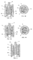
- a tubular member shown in FIGS. 7A to 7C can be used as the shield member 5.
- This tubular member is formed with a first tubular portion 56 having a constant wall thickness over a required axial region, and a second tubular portion 57 extending over the remaining axial region.
- the second tubular portion 57 has a constant wall thickness smaller than the first tubular portion 56.
- the outer diameter of the shield member 5 is substantially constant in the axial direction.
- a tubular member shown in FIGS. 8A to 8C may be used as the shield member 5.
- This tubular member is formed with a first tubular portion 70 having a constant outer diameter over a required axial region, and a second tubular portion 71 extending over another axial region.
- the second tubular portion 71 has the same wall thickness as the first tubular portion 70, but an outer diameter of the second tubular portion 71 is larger than that of the first tubular portion 70.
- This shield member 5 can be readily manufactured by drawing a metal material. The above explanation is directed to the shield member 5 having the two tubular portions with different outer diameters in the axial direction. If necessary, the shield member 5 may have three or more tubular portions with different outer diameters to improve the linearity of coil impedance.
- This shield member 5 is formed in a double tubular structure with an outer tube 73 and an inner tube 74 disposed in the outer tube 73 and having a shorter axial length than the outer tube 73.
- the shield member 5 is disposed such that the first flange 13 contacts an inner surface of the inner tube 74 and the second flange 14 contacts an inner surface of the outer tube 73.
- the outer and inner tubes (73, 74) can be made of a same material. Alternatively, as described in the second embodiment, they may be made of materials having different electrical conductivity or magnetic permeability.
- the shield member is characterized in that the distance between the shield member 5 and the detection coil 1 is different in the axial direction, and also the kind of material of the shield member is different in the axial direction. Therefore, this shield member 5 possesses both features of the second embodiment and the present embodiment.
- the above explanation is directed to the shield ember having the double tubular structure, as shown in FIG. 9A . If necessary, the shield member may have a triple or more tubular structure. In this case, the shield member is formed with at least three regions having different distances between the detection coil and the shield member in the axial direction.
- an insulating layer 75 may be formed between the inner tube 74 and the outer tube 73 of the shield member 5 having the double tubular structure described above.
- the inner tube 74 is supported by the first flange 13 of the detection coil 1
- the outer tube 73 is supported by the second flange 14 of the detection coil 1 .
- the insulating layer 75 is provided by an air between the inner tube 74 and the outer tube 73.
- the insulating layer is not limited to the air, and therefore may be formed by use of another electrical insulating material.
- a slit 51 may be formed in the shield member 5 shown in FIG.
- the slit 51 is formed in the inner tube 74 having a shorter length than the outer tube 73, which defines the entire length of the shield member 5. It means that a required axial region of the shield member 5 is formed in an electrically discontinuous manner with respect to the circumferential direction. This is equivalent to the feature of the shield member of the first embodiment. Therefore, it can be said that this shield member 5 has all of the features of the first to third embodiments.
- a hollow portion may be formed in the inner tube, as introduced in the first embodiment.
- the slit 51 or the hollow portion may be formed in a required axial region of the outer tube 73 in place of the inner tube 74.
- a flow pattern of eddy current in the shield member 5 changes depending on the cross-sectional shape and size of the shield member.
- a change amount of coil impedance caused when the magnetic core 2 is displaced by a unit length is influenced by the flow pattern of eddy current. Therefore, by appropriately determining the cross-sectional shape and size of each of the shield members described in the present embodiment, an increasing amount of coil impedance in a specific displacement range of the magnetic core 2 can be intentionally changed, so that it becomes possible to improve the linearity of impedance over all.
- the inner tube 74 is made of an iron-based metal that is a ferromagnetic material to obtain a desired magnetic shield effect.
- ferrite from the following reason. That is, since a general position sensor has a self-resonant frequency within a frequency band of several hundreds kHz to several tens MHz, it easily receives an influence of radiation noise in this frequency band. However, ferrite has a remarkable shield effect against this frequency band. Therefore, the influence of radiation noise in the above frequency band can be reduced by use of ferrite. In addition, the easiness of machining or processing is one of the advantages of ferrite.
- the outer tube 73 is made of a conductive material (e.g., copper, copper-nickel alloy, gold, silver) having higher electrical conductivity than the magnetic metal material used for the inner tube.
- a conductive material e.g., copper, copper-nickel alloy, gold, silver
- the impedance of the detection coil 1 was measured under a condition that a metal plate M1 is placed at a position spaced from the detection coil by a predetermined distance d2 , as shown in FIG. 12A .
- the impedance of the detection coil 1 was measured under a condition that the metal plate M1 is not placed.
- a change amount of impedance therebetween was calculated.
- the impedance was measured under a condition that an iron shield member S1 is placed at a position spaced from the detection coil 1 by a predetermined distance d1, and between the detection coil 1 and the metal plate M1, as shown in FIG. 12B .
- the change amount of impedance was calculated.
- the impedance was measured under a condition that a shield member having a double structure, which is composed of an iron shield member S1 and an additional shield member S2 that is a copper plating layer formed on an outer surface of the iron shield member S1 , is placed at a position spaced from the detection coil 1 by a predetermined distance d1, and between the detection coil 1 and the metal plate M1 , as shown in FIG. 12C .
- the change amount of impedance was calculated.
- the metal plate M1 three kinds of metal plates having a same thickness, i.e., iron, aluminum and brass plates were used. With respect each of the metal plates, the above tests were performed under the same conditions.
- the change in coil impedance can be effectively reduced by placing the shield member S1 and particularly the shield member having the double structure ( S1, S2 ).
- the axial length of the shield member 5 is not smaller than a distance corresponding to the movable range of the magnetic core 2 , as shown in FIG. 13 .
- the magnetic core 2 can be always shielded. Therefore, even when an outer conductor S is disposed in the vicinity of the shield member, most of magnetic fluxes of an external magnetic field E generated from the outer conductor S do not pass through the shield member. As a result, the magnetic fluxes of the external magnetic field E do not make interlinkage with the detection coil 1 to prevent that an induced electromotive force is generated in the detection coil 1 by the external magnetic field E.
- a shield member 5A of the present invention used in an impedance evaluation test is the same type as the shield member 5 of FIG. 8A of the third embodiment.
- This shield member 5A is made of a stainless steel (SUS304), and composed of a first tubular portion 70 having a small diameter and a second tubular portion 71 having a large diameter.
- the outer diameter ⁇ 1 of the first tubular portion 70 is 12 mm, and the outer diameter ⁇ 2 of the second tubular portion 71 is 16 mm.
- the first tubular portion 70 and the second tubular portion 71 of the shield member have a same wall thickness T that is 0.5 mm constant.
- an axial length S of the second tubular portion 71 is 5 mm.
- the axial length and the wall thickness T of the comparative shield member are the same as them of the shield member 5A shown in FIG. 14A .
- the right end of the shield member corresponds to a position that the displacement (X) is 100 mm, and the left end thereof is formed to be slightly longer than a position that the displacement (X) is 0 mm.
- the detection coil 1 is disposed in each of these shield members (5A, 58), and a change in impedance of the detection coil 1 relative to the displacement of the magnetic core 2 was measured. Results are shown in FIG. 14C .
- the shield member 5B when the displacement (X) exceeds 90 mm, the increasing amount of impedance gradually decreases, so that a deviation from the ideal characteristic occurs, as shown in FIG. 15 .
- the shield member 5A of the present invention even when the displacement (X) exceeds 95 mm, the linearity of impedance can be maintained. That is, it shows that the deviation from the ideal characteristic can be corrected by the formation of the second tubular portion 71.
- FIG. 14D shows a relationship between displacement and linearity error of coil impedance according to the above evaluation test results.
- the shield member having the cylindrical shape was mainly explained. However, the same effect of improving the linearity of coil impedance can be obtained in the case of using the shield member having a rectangular tubular shape.
- the position sensors of the above embodiments belong to a linear type (linear motion type) that the magnetic core is movable on a straight-line axis.
- the shield member of the present invention can be equivalently utilized for a rotational-type (curvilinear motion type) position sensor that the magnetic core is movable on a curved-line axis.
- the position sensor of the present invention since at least one of the shape of cross section, the kind of material and dimensions of the shield member is not uniform in an axial direction of the detection coil (a stroke direction of the magnetic core), and a detecting portion comprised of the magnetic core and the detection coil is disposed in the shield member, it is possible to improve the linearity of coil impedance, and consequently provide a compact position sensor with a stable detection accuracy over the stroke range of the magnetic core. Therefore, the position sensor of the present invention is expected to be used in various technical fields such as internal combustion and electric power facility.
Landscapes
- Physics & Mathematics (AREA)
- General Physics & Mathematics (AREA)
- Engineering & Computer Science (AREA)
- Technology Law (AREA)
- Transmission And Conversion Of Sensor Element Output (AREA)
- Measurement Of Length, Angles, Or The Like Using Electric Or Magnetic Means (AREA)
Applications Claiming Priority (3)
| Application Number | Priority Date | Filing Date | Title |
|---|---|---|---|
| JP2005140207A JP2006317283A (ja) | 2005-05-12 | 2005-05-12 | ポジションセンサ用の検出部、及びそれを用いたポジションセンサ |
| JP2005140208A JP2006317284A (ja) | 2005-05-12 | 2005-05-12 | ポジションセンサ用の検出部、及びそれを用いたポジションセンサ |
| EP06746329.9A EP1785697B8 (de) | 2005-05-12 | 2006-05-12 | Positionsgeber |
Related Parent Applications (1)
| Application Number | Title | Priority Date | Filing Date |
|---|---|---|---|
| EP06746329.9 Division | 2006-05-12 |
Publications (2)
| Publication Number | Publication Date |
|---|---|
| EP2244068A2 true EP2244068A2 (de) | 2010-10-27 |
| EP2244068A3 EP2244068A3 (de) | 2013-10-30 |
Family
ID=37396652
Family Applications (5)
| Application Number | Title | Priority Date | Filing Date |
|---|---|---|---|
| EP10172383.1A Withdrawn EP2244068A3 (de) | 2005-05-12 | 2006-05-12 | Positionssensor |
| EP10006298A Withdrawn EP2236989A3 (de) | 2005-05-12 | 2006-05-12 | Positionssensor |
| EP10172380.7A Withdrawn EP2244067A3 (de) | 2005-05-12 | 2006-05-12 | Positionssensor |
| EP06746331A Withdrawn EP1881298A4 (de) | 2005-05-12 | 2006-05-12 | Positionssensor |
| EP06746329.9A Not-in-force EP1785697B8 (de) | 2005-05-12 | 2006-05-12 | Positionsgeber |
Family Applications After (4)
| Application Number | Title | Priority Date | Filing Date |
|---|---|---|---|
| EP10006298A Withdrawn EP2236989A3 (de) | 2005-05-12 | 2006-05-12 | Positionssensor |
| EP10172380.7A Withdrawn EP2244067A3 (de) | 2005-05-12 | 2006-05-12 | Positionssensor |
| EP06746331A Withdrawn EP1881298A4 (de) | 2005-05-12 | 2006-05-12 | Positionssensor |
| EP06746329.9A Not-in-force EP1785697B8 (de) | 2005-05-12 | 2006-05-12 | Positionsgeber |
Country Status (4)
| Country | Link |
|---|---|
| US (2) | US7598734B2 (de) |
| EP (5) | EP2244068A3 (de) |
| KR (2) | KR100820262B1 (de) |
| WO (2) | WO2006121146A1 (de) |
Families Citing this family (20)
| Publication number | Priority date | Publication date | Assignee | Title |
|---|---|---|---|---|
| US20070002488A1 (en) * | 2005-07-04 | 2007-01-04 | Yamaha Corporation | Slide control device |
| US7812722B2 (en) * | 2007-02-28 | 2010-10-12 | Zircon Corporation | Dual orientation metal scanner |
| JP4960767B2 (ja) * | 2007-05-25 | 2012-06-27 | パナソニック株式会社 | 変位センサ |
| DE102007062397A1 (de) * | 2007-12-20 | 2009-06-25 | Endress + Hauser Flowtec Ag | Meßwandler vom Vibrationstyp |
| DE102009003080A1 (de) * | 2009-05-13 | 2010-11-18 | Robert Bosch Gmbh | Positionserfassungsanordnung für ein umlaufendes Transfersystem |
| US9360507B2 (en) * | 2011-12-19 | 2016-06-07 | Tyco Safety Products Canada Ltd. | Displacement tamper sensor and method |
| GB201122231D0 (en) * | 2011-12-23 | 2012-02-01 | Qinetiq Ltd | Proximity sensor |
| KR101351747B1 (ko) * | 2012-12-14 | 2014-01-15 | 한국항공우주연구원 | 센서 위치안내 치구 |
| DE102013222276A1 (de) * | 2013-11-01 | 2015-05-21 | Rolls-Royce Deutschland Ltd & Co Kg | Induktiver Sensor und Verfahren zum Herstellen eines induktiven Sensors |
| CN104266665B (zh) * | 2014-09-17 | 2016-09-28 | 上海兰宝传感科技股份有限公司 | 电感式传感器 |
| US9915144B2 (en) * | 2014-11-12 | 2018-03-13 | Baker Hughes, A Ge Company, Llc | Production logging tool with multi-sensor array |
| EP3203191A1 (de) * | 2016-02-03 | 2017-08-09 | Siemens Aktiengesellschaft | Sensor für ein magnetlager |
| SE541400C2 (en) * | 2017-02-27 | 2019-09-17 | Sem Ab | Inductive position sensor with improved plunger core design |
| EP3503135B1 (de) * | 2017-12-22 | 2023-04-26 | Hamilton Sundstrand Corporation | Elektromagnetische vorrichtung |
| US10998116B2 (en) * | 2018-02-23 | 2021-05-04 | Hamilton Sundstrand Corporation | VDT with high permeability shield |
| US11315725B2 (en) * | 2018-11-02 | 2022-04-26 | Analog Devices International Unlimited Company | Current sensing coil electrostatic shielding |
| JP7253356B2 (ja) * | 2018-11-12 | 2023-04-06 | オムロン株式会社 | センサ |
| US11046423B2 (en) * | 2019-07-18 | 2021-06-29 | Pratt & Whitney Canada Corp. | Blade angle position feedback system with magnetic shield |
| DE102020100581B4 (de) * | 2020-01-13 | 2023-06-22 | Rolf Prettl | Vorrichtung und Verfahren zur Messung einer Stromstärke |
| KR102204171B1 (ko) * | 2020-04-14 | 2021-01-19 | 대보정보통신 주식회사 | 복수 개의 서치코일 타입 센서를 이용한 멀티 측정 장치 |
Citations (4)
| Publication number | Priority date | Publication date | Assignee | Title |
|---|---|---|---|---|
| US3891918A (en) | 1971-03-23 | 1975-06-24 | James F Ellis | Linear displacement transducer utilizing an oscillator whose average period varies as a linear function of the displacement |
| US5003258A (en) | 1987-11-20 | 1991-03-26 | Vibro-Meter Sa | Position transducer with temperature dependency compensation having a coil and displaceable core made of conductive and ferromagnetic materials |
| US5206587A (en) | 1990-03-30 | 1993-04-27 | Mitchell Rose | Inductive displacement transducer having telescoping probe assembly |
| WO2004099727A1 (ja) | 2003-04-22 | 2004-11-18 | Matsushita Electric Works Ltd. | 変位検出装置 |
Family Cites Families (22)
| Publication number | Priority date | Publication date | Assignee | Title |
|---|---|---|---|---|
| JPS4219122Y1 (de) | 1965-12-25 | 1967-11-06 | ||
| JPS582683B2 (ja) | 1979-12-18 | 1983-01-18 | ワイケイケイ株式会社 | 開離嵌插具付スライドフアスナ−の左右ストリンガ−仮組合せ方法とその装置 |
| JPS56104603U (de) * | 1980-01-16 | 1981-08-15 | ||
| US4406999A (en) * | 1980-04-07 | 1983-09-27 | Clarostat Mfg. Co., Inc. | Inductive sensor |
| US4627280A (en) * | 1984-04-24 | 1986-12-09 | Toyoda Gosei Co., Ltd. | Inductance liquid level meter |
| US4667158A (en) * | 1985-04-01 | 1987-05-19 | Redlich Robert W | Linear position transducer and signal processor |
| EP0258468B1 (de) | 1986-08-28 | 1990-01-24 | Vickers Systems GmbH | Verfahren zur induktiven Wegmessung und Wegsensor |
| JPS63265115A (ja) * | 1986-12-04 | 1988-11-01 | Ckd Controls Ltd | 変位センサ |
| JPH0624732Y2 (ja) * | 1987-06-30 | 1994-06-29 | 日本電気ホームエレクトロニクス株式会社 | 差動トランス |
| US4912409A (en) * | 1988-01-22 | 1990-03-27 | Sunpower, Inc. | Actuator displacement transducer having external flux excluding tube |
| US5045785A (en) | 1990-03-05 | 1991-09-03 | Borg-Warner Automotive, Inc. | Linear position sensor with movable tapered element |
| JPH0534506A (ja) | 1991-08-02 | 1993-02-12 | Olympus Optical Co Ltd | 耐薬反射防止膜 |
| JPH0735961B2 (ja) | 1991-09-11 | 1995-04-19 | 株式会社エム・システム技研 | 変位検出用差動トランス及び角度検出器 |
| JPH0534506U (ja) * | 1991-10-14 | 1993-05-07 | 豊田工機株式会社 | 変位量検出装置 |
| DE4225533A1 (de) | 1992-08-01 | 1994-02-03 | Hottinger Messtechnik Baldwin | Elektrischer Wegsensor |
| JP2001021306A (ja) * | 1999-07-08 | 2001-01-26 | Mitsumi Electric Co Ltd | 位置センサ回路 |
| JP2001272201A (ja) * | 2000-03-27 | 2001-10-05 | Sony Precision Technology Inc | 位置検出装置 |
| JP4334750B2 (ja) | 2000-09-18 | 2009-09-30 | 株式会社日本自動車部品総合研究所 | 差動トランス式変位センサ |
| WO2002044647A2 (en) * | 2000-11-30 | 2002-06-06 | Asylum Research Corporation | Improved linear variable differential transformers for high precision position measurements |
| JP2002344188A (ja) | 2001-05-17 | 2002-11-29 | Mitsubishi Electric Corp | 磁気シールド付計測機器 |
| CN1247961C (zh) | 2001-06-29 | 2006-03-29 | 松下电工株式会社 | 位置传感器 |
| DE10155063A1 (de) * | 2001-11-09 | 2003-05-22 | Wabco Gmbh & Co Ohg | Induktiver Wegsensor, integriert in einen Hydrospeicher |
-
2006
- 2006-05-12 EP EP10172383.1A patent/EP2244068A3/de not_active Withdrawn
- 2006-05-12 EP EP10006298A patent/EP2236989A3/de not_active Withdrawn
- 2006-05-12 EP EP10172380.7A patent/EP2244067A3/de not_active Withdrawn
- 2006-05-12 EP EP06746331A patent/EP1881298A4/de not_active Withdrawn
- 2006-05-12 KR KR1020077006368A patent/KR100820262B1/ko not_active Expired - Fee Related
- 2006-05-12 US US11/574,610 patent/US7598734B2/en not_active Expired - Fee Related
- 2006-05-12 US US11/575,009 patent/US7679361B2/en not_active Expired - Fee Related
- 2006-05-12 EP EP06746329.9A patent/EP1785697B8/de not_active Not-in-force
- 2006-05-12 WO PCT/JP2006/309534 patent/WO2006121146A1/ja not_active Ceased
- 2006-05-12 WO PCT/JP2006/309532 patent/WO2006121145A1/ja not_active Ceased
- 2006-05-12 KR KR1020077008229A patent/KR100868011B1/ko not_active Expired - Fee Related
Patent Citations (4)
| Publication number | Priority date | Publication date | Assignee | Title |
|---|---|---|---|---|
| US3891918A (en) | 1971-03-23 | 1975-06-24 | James F Ellis | Linear displacement transducer utilizing an oscillator whose average period varies as a linear function of the displacement |
| US5003258A (en) | 1987-11-20 | 1991-03-26 | Vibro-Meter Sa | Position transducer with temperature dependency compensation having a coil and displaceable core made of conductive and ferromagnetic materials |
| US5206587A (en) | 1990-03-30 | 1993-04-27 | Mitchell Rose | Inductive displacement transducer having telescoping probe assembly |
| WO2004099727A1 (ja) | 2003-04-22 | 2004-11-18 | Matsushita Electric Works Ltd. | 変位検出装置 |
Also Published As
| Publication number | Publication date |
|---|---|
| EP2244067A3 (de) | 2013-10-30 |
| US7598734B2 (en) | 2009-10-06 |
| EP1881298A1 (de) | 2008-01-23 |
| WO2006121146A1 (ja) | 2006-11-16 |
| EP2236989A3 (de) | 2012-12-12 |
| EP2236989A2 (de) | 2010-10-06 |
| US7679361B2 (en) | 2010-03-16 |
| KR100868011B1 (ko) | 2008-11-10 |
| EP2244067A2 (de) | 2010-10-27 |
| US20080315868A1 (en) | 2008-12-25 |
| EP1785697A1 (de) | 2007-05-16 |
| EP1785697B8 (de) | 2013-11-13 |
| KR100820262B1 (ko) | 2008-04-08 |
| KR20070069145A (ko) | 2007-07-02 |
| EP1785697A4 (de) | 2009-12-30 |
| EP1785697B1 (de) | 2013-07-31 |
| US20080258739A1 (en) | 2008-10-23 |
| EP1881298A4 (de) | 2009-06-17 |
| EP2244068A3 (de) | 2013-10-30 |
| KR20070054721A (ko) | 2007-05-29 |
| WO2006121145A1 (ja) | 2006-11-16 |
Similar Documents
| Publication | Publication Date | Title |
|---|---|---|
| EP1785697B1 (de) | Positionsgeber | |
| EP0366227B1 (de) | Verschiebungsmessapparat | |
| JP4135551B2 (ja) | ポジションセンサ | |
| CN1333234C (zh) | 位移检测器 | |
| US6983661B2 (en) | Electromagnetic flow sensor | |
| US6504361B1 (en) | Inductive measurement transducer for determining a position of a moving body | |
| US6580264B2 (en) | Position detector with magnetic core and detection and auxiliary coils | |
| CN100473951C (zh) | 位置传感器 | |
| US7812597B2 (en) | Inductive magnetic position sensor | |
| JPS60501434A (ja) | 能動型変流器 | |
| US5867022A (en) | Inductive angle-of-rotation sensor having rotatable magnetically conductive element within single winding coil | |
| JP4618192B2 (ja) | ポジションセンサ | |
| US20090184707A1 (en) | Electromagnetic barrier for use in association with inductive position sensors | |
| JP2003075106A (ja) | 位置検出装置 | |
| KR20190088350A (ko) | 변위 센서 | |
| JPS63273001A (ja) | 変位測定装置 | |
| JP4682913B2 (ja) | ポジションセンサ | |
| WO2019142780A1 (ja) | 位置検出装置 | |
| CN223320520U (zh) | 一种串入式电弧传感器 | |
| JP2006317284A (ja) | ポジションセンサ用の検出部、及びそれを用いたポジションセンサ | |
| KR20040055747A (ko) | 이중코일형 선형가변차동변환기 | |
| JP2025099880A (ja) | 位置検出装置 | |
| JP2008070215A (ja) | ポジションセンサ用の検出部、及びポジションセンサ | |
| JP2004144626A (ja) | 折畳み型伸縮誘導子による変位計の構造 |
Legal Events
| Date | Code | Title | Description |
|---|---|---|---|
| PUAI | Public reference made under article 153(3) epc to a published international application that has entered the european phase |
Free format text: ORIGINAL CODE: 0009012 |
|
| AC | Divisional application: reference to earlier application |
Ref document number: 1785697 Country of ref document: EP Kind code of ref document: P |
|
| AK | Designated contracting states |
Kind code of ref document: A2 Designated state(s): DE FR GB IT |
|
| 17P | Request for examination filed |
Effective date: 20101029 |
|
| RAP1 | Party data changed (applicant data changed or rights of an application transferred) |
Owner name: PANASONIC CORPORATION |
|
| PUAL | Search report despatched |
Free format text: ORIGINAL CODE: 0009013 |
|
| AK | Designated contracting states |
Kind code of ref document: A3 Designated state(s): DE FR GB IT |
|
| RIC1 | Information provided on ipc code assigned before grant |
Ipc: G01D 5/20 20060101AFI20130923BHEP |
|
| RAP1 | Party data changed (applicant data changed or rights of an application transferred) |
Owner name: PANASONIC INTELLECTUAL PROPERTY MANAGEMENT CO., LT |
|
| RAP1 | Party data changed (applicant data changed or rights of an application transferred) |
Owner name: PANASONIC INTELLECTUAL PROPERTY MANAGEMENT CO., LT |
|
| STAA | Information on the status of an ep patent application or granted ep patent |
Free format text: STATUS: THE APPLICATION HAS BEEN WITHDRAWN |
|
| 18W | Application withdrawn |
Effective date: 20170621 |