EP2243567B1 - Dispositif de fabrication de tuyaux ondulés transversalement par rapport à leur direction longitudinale - Google Patents
Dispositif de fabrication de tuyaux ondulés transversalement par rapport à leur direction longitudinale Download PDFInfo
- Publication number
- EP2243567B1 EP2243567B1 EP09290297A EP09290297A EP2243567B1 EP 2243567 B1 EP2243567 B1 EP 2243567B1 EP 09290297 A EP09290297 A EP 09290297A EP 09290297 A EP09290297 A EP 09290297A EP 2243567 B1 EP2243567 B1 EP 2243567B1
- Authority
- EP
- European Patent Office
- Prior art keywords
- tube
- end position
- corrugated
- closed
- station
- Prior art date
- Legal status (The legal status is an assumption and is not a legal conclusion. Google has not performed a legal analysis and makes no representation as to the accuracy of the status listed.)
- Not-in-force
Links
Images

Classifications
-
- B—PERFORMING OPERATIONS; TRANSPORTING
- B21—MECHANICAL METAL-WORKING WITHOUT ESSENTIALLY REMOVING MATERIAL; PUNCHING METAL
- B21C—MANUFACTURE OF METAL SHEETS, WIRE, RODS, TUBES OR PROFILES, OTHERWISE THAN BY ROLLING; AUXILIARY OPERATIONS USED IN CONNECTION WITH METAL-WORKING WITHOUT ESSENTIALLY REMOVING MATERIAL
- B21C37/00—Manufacture of metal sheets, bars, wire, tubes or like semi-manufactured products, not otherwise provided for; Manufacture of tubes of special shape
- B21C37/06—Manufacture of metal sheets, bars, wire, tubes or like semi-manufactured products, not otherwise provided for; Manufacture of tubes of special shape of tubes or metal hoses; Combined procedures for making tubes, e.g. for making multi-wall tubes
- B21C37/08—Making tubes with welded or soldered seams
- B21C37/0807—Tube treating or manipulating combined with, or specially adapted for use in connection with tube making machines, e.g. drawing-off devices, cutting-off
-
- B—PERFORMING OPERATIONS; TRANSPORTING
- B21—MECHANICAL METAL-WORKING WITHOUT ESSENTIALLY REMOVING MATERIAL; PUNCHING METAL
- B21C—MANUFACTURE OF METAL SHEETS, WIRE, RODS, TUBES OR PROFILES, OTHERWISE THAN BY ROLLING; AUXILIARY OPERATIONS USED IN CONNECTION WITH METAL-WORKING WITHOUT ESSENTIALLY REMOVING MATERIAL
- B21C37/00—Manufacture of metal sheets, bars, wire, tubes or like semi-manufactured products, not otherwise provided for; Manufacture of tubes of special shape
- B21C37/06—Manufacture of metal sheets, bars, wire, tubes or like semi-manufactured products, not otherwise provided for; Manufacture of tubes of special shape of tubes or metal hoses; Combined procedures for making tubes, e.g. for making multi-wall tubes
- B21C37/15—Making tubes of special shape; Making tube fittings
- B21C37/20—Making helical or similar guides in or on tubes without removing material, e.g. by drawing same over mandrels, by pushing same through dies ; Making tubes with angled walls, ribbed tubes and tubes with decorated walls
- B21C37/205—Making helical or similar guides in or on tubes without removing material, e.g. by drawing same over mandrels, by pushing same through dies ; Making tubes with angled walls, ribbed tubes and tubes with decorated walls with annular guides
-
- B—PERFORMING OPERATIONS; TRANSPORTING
- B21—MECHANICAL METAL-WORKING WITHOUT ESSENTIALLY REMOVING MATERIAL; PUNCHING METAL
- B21D—WORKING OR PROCESSING OF SHEET METAL OR METAL TUBES, RODS OR PROFILES WITHOUT ESSENTIALLY REMOVING MATERIAL; PUNCHING METAL
- B21D15/00—Corrugating tubes
- B21D15/04—Corrugating tubes transversely, e.g. helically
- B21D15/06—Corrugating tubes transversely, e.g. helically annularly
Definitions
- the invention relates to an apparatus for the production of tubes corrugated transversely to their longitudinal direction, comprising a forming unit in which a metal strip is longitudinally formed into a slit tube having a longitudinal slot, a welding unit in which the slit for obtaining a closed Pipe is welded, a shaft means in which the closed tube is provided with a corrugation, and a take-off device which has two in the longitudinal direction of the tube between a starting position and an end position reciprocating jaws which alternately engage the tube and the same in move its longitudinal direction, wherein in each case one of the jaws pulls the tube until it reaches its end position, while the other is moved back from its end position to its initial position ( DE-B-2 203 474 ).
- a tube according to the invention may be a hollow structure for transporting fluid media or an electromagnetic waveguide, but also a sheath or conductor present in the construction of electrical cables. Due to the corrugated design, the tube is much better bendable than a smooth tube. The shaping of the tube from a longitudinally running metal band allows a continuous production of the same in great lengths. Because of the corrugation, the tube can easily be wound up on spools.
- the slot of the tube is welded and the corrugation is pressed into the closed tube by means of a corrugation tool rotating in the circumferential direction around the tube. It must be ensured that the tube is not rotated by the corrugated tool in the circumferential direction, so that the slot to be welded is not unscrewed from the welding area. That can with so-called Collet chucks are ensured in which the tube is held firmly over a longer distance by a plurality of jaws.
- a collet trigger is for example in the EP 0 442 037 B1 described.
- the trigger device according to the above-mentioned DE-C-2 203 474 has only two jaws, which are alternately in use during the withdrawal of the tube. While one of the clamping jaws pulls the tube in its longitudinal direction, starting from a starting position to an end position, the other is moved back into its starting position in the opened state. It then takes over the drawing process again when the clamping jaw in use has reached its end position and is then opened.
- this known device is shorter than known devices with collets.
- the two interchangeable jaws can not hold the tube sufficiently to eliminate repercussions on the welding operation in closing the longitudinally extending slot in the welding unit.
- the invention has the object of developing the above-described device so that repercussions on the welding process when closing the tube can be excluded.
- a stationary holding device is provided with at least two movable in the withdrawal direction of the tube on an endless web clamping elements, which are arranged diametrically opposite each other with respect to the tube and rest firmly in working position on the pipe.
- the sealed in the welding unit tube passes behind the welding unit acting as a fixed holding device through which the tube is held so tight that it can not be rotated about its axis.
- the tube is still moved with a compact, short-building trigger, which consists of two alternately effective jaws, it is thus ensured that the longitudinal seam is not displaced from its position, but constantly fit through the welding unit is pulled. The weld is thus constantly produced under optimal conditions.
- a device is shown by means of which from a metallic strip a transversely to its longitudinal direction corrugated tube R is produced.
- the band consists for example of steel or copper. It is withdrawn from a coil SP and in the direction of arrow P by the device after Fig. 1 emotional.
- the metallic strip is first fed to a forming unit 1, in which it is longitudinally formed into a slot tube.
- the word "slotted tube” describes a tube having a slot extending along a surface line in which the two edges of the band abut each other.
- the slot is welded in a withdrawal direction behind the forming unit 1 lying welding unit 2, so that a completely closed tube 3 results.
- the closed tube 3 is moved by means of a two jaws 4 and 5
- Exhaust device AV in the direction of arrow P and fed to a shaft means 6, in which it is provided to obtain the tube R with a transverse to its longitudinal direction corrugation.
- the device also includes a holding device 7, which is arranged in the illustrated embodiment between the welding unit 2 and shaft means 6.
- Forming unit 1, welding unit 2 and shaft 6 are basically known. They are therefore in Fig. 1 only indicated schematically.
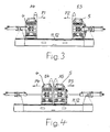
- Both jaws 4 and 5 are constantly reciprocated during operation of the device between two positions. These are a working position in which the respective jaw is closed until the fixed contact with the pipe 3, and an end position in which the respective jaw is opened again.
- the maximum distance between the two jaws 4 and 5 from each other for example, be 2 m, so that each jaw travels a distance of about 1 m between its working position and its end position.
- the jaws 4 and 5 are alternately in use. While one jaw pulls the closed tube 3 in the direction of arrow P, the other, which has pulled the tube 3 before, opened and moved back to its original position, in which they can take over the transport of the tube 3 again. During ongoing operation of the device, the jaws 4 and 5 are briefly closed in a transitional phase both for a short time to ensure a continuous movement of the tube 3.
- Fig. 3 The positions of the jaws 4 and 5 are apparent in which there is the maximum distance between them.
- the jaw 4 is in its division of labor A4, in which it is closed and the tube 3 can pull in the direction of the arrow P1.
- the jaw 5 is in its end position E5, to which it has pulled the tube 3. It remains closed until the jaw 4 is closed and has started to pull the tube 3. Thereafter, the jaw 5 is opened and on the rails 11 and 12 in the direction of the arrow P2 in its working position A5 ( Fig. 4 ) moved back.
- the clamping jaw 4 pulls the tube 3 until it reaches its end position E4 (FIG. Fig. 4 ) has reached, which is in the amount of the working position A5 of the jaw 5. This is then closed and pulls - analogous to the procedure described for the jaw 4 - the tube 3 in the direction of arrow P3. The jaw 4 is moved back simultaneously in the open state in the direction of arrow P4 in its working position A4.
- the holding device 7, is the holding device 7, according to Fig. 1 between the welding unit 3 and the exhaust device AV can be arranged.
- the weld in the welding unit 3 is then relieved immediately opposite circumferentially acting forces.
- the holding device 7 can also be positioned between the extraction device AV and the shaft device 6.
- the force exerted by the shaft means 6 on the tube 3 in its circumferential direction is then absorbed directly. In both positions, the holding device 7 prevents rotation of the tube 3 about its axis, so that the slot to be welded is always positioned correctly in the welding unit 2.
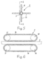
- the holding device 7 has in the embodiment according to Fig. 5 four circumferentially offset from each other clamping elements 15.
- the clamping elements 15 are corresponding Fig. 6 each movable on an endless track 16. They are, for example, as bands or chains around two wheels 17 and 18 moved around and lie in working position firmly on the tube 3 at.
- the movement of the clamping elements 15 along the endless track 16 can be effected by the tube 3 itself, which entrains the same because of the fixed system. But they can also be driven, comparable to a caterpillar take-off.
- the extraction device AV can also have more than two clamping elements 15, which are arranged offset relative to one another with respect to the tube 3 in the circumferential direction, as it is in Fig. 5 for four clamping elements 15 is shown.
Landscapes
- Engineering & Computer Science (AREA)
- Mechanical Engineering (AREA)
- Butt Welding And Welding Of Specific Article (AREA)
- Heat-Exchange Devices With Radiators And Conduit Assemblies (AREA)
- Exhaust Gas After Treatment (AREA)
- Bending Of Plates, Rods, And Pipes (AREA)
- Lining Or Joining Of Plastics Or The Like (AREA)
Claims (3)
- Dispositif de fabrication de tuyaux ondulés transversalement par rapport à leur direction longitudinale, composé d'une unité de façonnage (1) dans laquelle une bande de métal est façonnée en avançant dans le sens de la longueur pour prendre la forme d'un tuyau fendu doté d'une fente s'étendant dans la direction longitudinale, d'une unité de soudage (2) dans laquelle la fente est soudée pour obtenir un tuyau fermé, d'un dispositif d'ondulation (6) dans lequel le tuyau fermé est amené à gondoler et d'un dispositif de retrait (AV) disposé entre l'unité de soudage (2) et le dispositif d'ondulation (6) qui comporte deux mâchoires de serrage (4, 5) réalisant un mouvement de va-et-vient dans la direction longitudinale du tuyau (3) entre une position de départ et une position finale, lesdites mâchoires s'agrippant de façon alternée au tuyau et le déplaçant dans sa direction longitudinale, respectivement une des mâchoires de serrage tirant le tuyau jusqu'à atteindre sa position finale tandis que l'autre est ramenée de sa position finale dans sa position de départ, caractérisé en ce qu'en outre, un dispositif d'arrêt (7) fixe sur place est pourvu d'au moins deux éléments de serrage (15) mobiles dans la direction de retrait du tuyau (3), sur une courroie sans fin (16), lesdits éléments étant disposés de façon diamétralement opposée au tuyau (3) et reposant dans la position de travail fixement contre le tuyau (3).
- Dispositif selon la revendication 1, caractérisé en ce que le dispositif d'arrêt (7) est disposé entre l'unité de soudage (2) et le dispositif de retrait (AV).
- Dispositif selon la revendication 1, caractérisé en ce que le dispositif d'arrêt (7) est disposé entre le dispositif de retrait (AV) et le dispositif d'ondulation (6).
Priority Applications (4)
| Application Number | Priority Date | Filing Date | Title |
|---|---|---|---|
| DK09290297.2T DK2243567T3 (da) | 2009-04-21 | 2009-04-21 | Indretning til fremstilling af rør, der er korrugerede på tværs af længde-retningen |
| EP09290297A EP2243567B1 (fr) | 2009-04-21 | 2009-04-21 | Dispositif de fabrication de tuyaux ondulés transversalement par rapport à leur direction longitudinale |
| DE502009000442T DE502009000442D1 (de) | 2009-04-21 | 2009-04-21 | Vorrichtung zur Herstellung von quer zu ihrer Längsrichtung gewellten Rohren |
| AT09290297T ATE500906T1 (de) | 2009-04-21 | 2009-04-21 | Vorrichtung zur herstellung von quer zu ihrer längsrichtung gewellten rohren |
Applications Claiming Priority (1)
| Application Number | Priority Date | Filing Date | Title |
|---|---|---|---|
| EP09290297A EP2243567B1 (fr) | 2009-04-21 | 2009-04-21 | Dispositif de fabrication de tuyaux ondulés transversalement par rapport à leur direction longitudinale |
Publications (2)
| Publication Number | Publication Date |
|---|---|
| EP2243567A1 EP2243567A1 (fr) | 2010-10-27 |
| EP2243567B1 true EP2243567B1 (fr) | 2011-03-09 |
Family
ID=41011957
Family Applications (1)
| Application Number | Title | Priority Date | Filing Date |
|---|---|---|---|
| EP09290297A Not-in-force EP2243567B1 (fr) | 2009-04-21 | 2009-04-21 | Dispositif de fabrication de tuyaux ondulés transversalement par rapport à leur direction longitudinale |
Country Status (4)
| Country | Link |
|---|---|
| EP (1) | EP2243567B1 (fr) |
| AT (1) | ATE500906T1 (fr) |
| DE (1) | DE502009000442D1 (fr) |
| DK (1) | DK2243567T3 (fr) |
Families Citing this family (3)
| Publication number | Priority date | Publication date | Assignee | Title |
|---|---|---|---|---|
| CN103537520A (zh) * | 2012-07-09 | 2014-01-29 | 广州众信实业有限公司 | 一种金属螺旋波纹管成型装置 |
| CN107116109A (zh) * | 2017-07-01 | 2017-09-01 | 浙江义腾特种钢管有限公司 | 一种冷凝器用不锈钢管的生产工艺 |
| CN112091027B (zh) * | 2020-09-04 | 2021-04-16 | 航天晨光股份有限公司 | 一种定尺寸长度的无缝薄壁波纹管滚压成型机 |
Family Cites Families (6)
| Publication number | Priority date | Publication date | Assignee | Title |
|---|---|---|---|---|
| DE1216827B (de) * | 1962-02-01 | 1966-05-18 | Hackethal Draht & Kabelwerk Ag | Abzugsvorrichtung an einer Einrichtung zur Herstellung duennwandiger, nahtgeschweisster und gewellter Rohre |
| US3700158A (en) * | 1970-04-23 | 1972-10-24 | Friedrich Schatz | Apparatus for making thin walled metal tubing |
| DE2203474C2 (de) * | 1972-01-26 | 1973-11-29 | Felten & Guilleaume Kabelwerke Ag, 5000 Koeln | Abzugsvorrichtung fur stranglbrmiges Gut |
| DE4004312A1 (de) * | 1990-02-13 | 1991-08-14 | Kabelmetal Electro Gmbh | Vorrichtung zum abziehen und/oder fuehren von langgestrecktem gut |
| DK1084774T3 (da) * | 2000-01-28 | 2003-04-22 | Nexans | Fremgangsmåde til kontinuerlig fremstilling af langsømsvejsede og korrugerede metalrør og indretning til gennemførelse af fremgangsmåden |
| ATE248037T1 (de) * | 2000-08-17 | 2003-09-15 | Nexans | Vorrichtung zur herstellung ringförming gewellter metallrohre |
-
2009
- 2009-04-21 DE DE502009000442T patent/DE502009000442D1/de active Active
- 2009-04-21 EP EP09290297A patent/EP2243567B1/fr not_active Not-in-force
- 2009-04-21 AT AT09290297T patent/ATE500906T1/de active
- 2009-04-21 DK DK09290297.2T patent/DK2243567T3/da active
Also Published As
| Publication number | Publication date |
|---|---|
| DK2243567T3 (da) | 2011-06-27 |
| EP2243567A1 (fr) | 2010-10-27 |
| DE502009000442D1 (de) | 2011-04-21 |
| ATE500906T1 (de) | 2011-03-15 |
Similar Documents
| Publication | Publication Date | Title |
|---|---|---|
| CH272636A (de) | Kontinuierliches elektrisches Stumpfnahtschweissverfahren zur Herstellung von Rohren und Einrichtung zur Durchführung dieses Verfahrens. | |
| EP0701878B1 (fr) | Dispositif et procédé de fabrication de tuyaux | |
| DE102006027046B3 (de) | Verfahren und Vorrichtung zum Herstellen eines Rohres | |
| EP2243567B1 (fr) | Dispositif de fabrication de tuyaux ondulés transversalement par rapport à leur direction longitudinale | |
| EP2428452B1 (fr) | Procédé et dispositif de banderolage pour l'installation de bandes de cerclage autour de pièces d'emballage | |
| DE1962184A1 (de) | Verfahren zur Herstellung von sich verjuengenden Masten | |
| EP0317905A2 (fr) | Procédé d'étirage des tuyaux métalliques sans soudure | |
| EP2675608B1 (fr) | Installation de soudage d'un revetement tubulaire pour une conduite d'eaux usees | |
| DE2934115C2 (de) | Verfahren und Vorrichtung zum Speichern endloser Metallbänder aus endlichen Walzbandlängen | |
| DE102009043454B4 (de) | Rillschlauchspannvorrichtung | |
| EP2845664A1 (fr) | Procédé et dispositif de fabrication d'un tuyau ondulé en métal | |
| DE2455902C3 (de) | Verfahren zur Herstellung von Tübbing- bzw. Tunnelausbausegmenten und Einrichtungen zur Durchführung des Verfahrens | |
| AT395386B (de) | Verfahren und anlage zum herstellen zweilagiger geschweisster gitterkoerper | |
| DE1176462B (de) | Vorrichtung zum Herstellen von im Querschnitt unrunden Papphuelsen aus im Querschnitt runden Huelsen | |
| DE2033691C3 (de) | Vorrichtung zur Herstellung eines rohrförmigen flexiblen Körpers | |
| DE102015109433A1 (de) | Verfahren und Vorrichtung zur Wandverformung eines rohrförmigen Werkstücks | |
| EP0042450B1 (fr) | Procédé pour la fabrication d'enveloppes de pots d'échappement à joint longitudinal plié et dispositif pour la réalisation de ce procédé | |
| DE2123628A1 (de) | Verfahren und Vorrichtung zum Aufblasen langer Längen aus zusammengesetzten Metallstreifen | |
| DE547714C (de) | Maschine zum Herstellen von Rohrbogen o. dgl. | |
| DE2354161B2 (de) | Vorrichtung zur kontinuierlichen Herstellung von längsgeschweißten Rohren aus Metallband | |
| DE202009009887U1 (de) | Durchlaufschweißmaschine | |
| EP3445508B1 (fr) | Dispositif et procédé de production d'un tuyau hélicoïdal | |
| DE2742026C3 (de) | Rohrformmaschine | |
| DE2118278C3 (de) | Verfahren und Vorrichtung zum kontinuierlichen Ziehen von langgestrecktem Gut | |
| DE8219048U1 (de) | Vorrichtung zum biegen von duennwandigen rohren, insbesondere mano meterfedern |
Legal Events
| Date | Code | Title | Description |
|---|---|---|---|
| PUAI | Public reference made under article 153(3) epc to a published international application that has entered the european phase |
Free format text: ORIGINAL CODE: 0009012 |
|
| 17P | Request for examination filed |
Effective date: 20090924 |
|
| AK | Designated contracting states |
Kind code of ref document: A1 Designated state(s): AT BE BG CH CY CZ DE DK EE ES FI FR GB GR HR HU IE IS IT LI LT LU LV MC MK MT NL NO PL PT RO SE SI SK TR |
|
| AX | Request for extension of the european patent |
Extension state: AL BA RS |
|
| GRAP | Despatch of communication of intention to grant a patent |
Free format text: ORIGINAL CODE: EPIDOSNIGR1 |
|
| RIC1 | Information provided on ipc code assigned before grant |
Ipc: B21D 15/06 20060101ALI20101029BHEP Ipc: B21C 37/08 20060101AFI20101029BHEP Ipc: B21C 37/20 20060101ALI20101029BHEP |
|
| GRAS | Grant fee paid |
Free format text: ORIGINAL CODE: EPIDOSNIGR3 |
|
| GRAA | (expected) grant |
Free format text: ORIGINAL CODE: 0009210 |
|
| AK | Designated contracting states |
Kind code of ref document: B1 Designated state(s): AT BE BG CH CY CZ DE DK EE ES FI FR GB GR HR HU IE IS IT LI LT LU LV MC MK MT NL NO PL PT RO SE SI SK TR |
|
| REG | Reference to a national code |
Ref country code: GB Ref legal event code: FG4D Free format text: NOT ENGLISH |
|
| REG | Reference to a national code |
Ref country code: CH Ref legal event code: EP |
|
| RAP2 | Party data changed (patent owner data changed or rights of a patent transferred) |
Owner name: NEXANS |
|
| REG | Reference to a national code |
Ref country code: IE Ref legal event code: FG4D Free format text: LANGUAGE OF EP DOCUMENT: GERMAN |
|
| REF | Corresponds to: |
Ref document number: 502009000442 Country of ref document: DE Date of ref document: 20110421 Kind code of ref document: P |
|
| REG | Reference to a national code |
Ref country code: DE Ref legal event code: R096 Ref document number: 502009000442 Country of ref document: DE Effective date: 20110421 |
|
| REG | Reference to a national code |
Ref country code: DK Ref legal event code: T3 |
|
| REG | Reference to a national code |
Ref country code: NL Ref legal event code: VDEP Effective date: 20110309 |
|
| REG | Reference to a national code |
Ref country code: NO Ref legal event code: T2 Effective date: 20110309 |
|
| PG25 | Lapsed in a contracting state [announced via postgrant information from national office to epo] |
Ref country code: GR Free format text: LAPSE BECAUSE OF FAILURE TO SUBMIT A TRANSLATION OF THE DESCRIPTION OR TO PAY THE FEE WITHIN THE PRESCRIBED TIME-LIMIT Effective date: 20110610 Ref country code: LT Free format text: LAPSE BECAUSE OF FAILURE TO SUBMIT A TRANSLATION OF THE DESCRIPTION OR TO PAY THE FEE WITHIN THE PRESCRIBED TIME-LIMIT Effective date: 20110309 Ref country code: SE Free format text: LAPSE BECAUSE OF FAILURE TO SUBMIT A TRANSLATION OF THE DESCRIPTION OR TO PAY THE FEE WITHIN THE PRESCRIBED TIME-LIMIT Effective date: 20110309 Ref country code: HR Free format text: LAPSE BECAUSE OF FAILURE TO SUBMIT A TRANSLATION OF THE DESCRIPTION OR TO PAY THE FEE WITHIN THE PRESCRIBED TIME-LIMIT Effective date: 20110309 Ref country code: ES Free format text: LAPSE BECAUSE OF FAILURE TO SUBMIT A TRANSLATION OF THE DESCRIPTION OR TO PAY THE FEE WITHIN THE PRESCRIBED TIME-LIMIT Effective date: 20110620 Ref country code: LV Free format text: LAPSE BECAUSE OF FAILURE TO SUBMIT A TRANSLATION OF THE DESCRIPTION OR TO PAY THE FEE WITHIN THE PRESCRIBED TIME-LIMIT Effective date: 20110309 |
|
| LTIE | Lt: invalidation of european patent or patent extension |
Effective date: 20110309 |
|
| PG25 | Lapsed in a contracting state [announced via postgrant information from national office to epo] |
Ref country code: CY Free format text: LAPSE BECAUSE OF FAILURE TO SUBMIT A TRANSLATION OF THE DESCRIPTION OR TO PAY THE FEE WITHIN THE PRESCRIBED TIME-LIMIT Effective date: 20110309 Ref country code: NL Free format text: LAPSE BECAUSE OF FAILURE TO SUBMIT A TRANSLATION OF THE DESCRIPTION OR TO PAY THE FEE WITHIN THE PRESCRIBED TIME-LIMIT Effective date: 20110309 Ref country code: SI Free format text: LAPSE BECAUSE OF FAILURE TO SUBMIT A TRANSLATION OF THE DESCRIPTION OR TO PAY THE FEE WITHIN THE PRESCRIBED TIME-LIMIT Effective date: 20110309 Ref country code: BG Free format text: LAPSE BECAUSE OF FAILURE TO SUBMIT A TRANSLATION OF THE DESCRIPTION OR TO PAY THE FEE WITHIN THE PRESCRIBED TIME-LIMIT Effective date: 20110609 Ref country code: FI Free format text: LAPSE BECAUSE OF FAILURE TO SUBMIT A TRANSLATION OF THE DESCRIPTION OR TO PAY THE FEE WITHIN THE PRESCRIBED TIME-LIMIT Effective date: 20110309 |
|
| REG | Reference to a national code |
Ref country code: IE Ref legal event code: FD4D |
|
| BERE | Be: lapsed |
Owner name: NEXANS Effective date: 20110430 |
|
| PG25 | Lapsed in a contracting state [announced via postgrant information from national office to epo] |
Ref country code: EE Free format text: LAPSE BECAUSE OF FAILURE TO SUBMIT A TRANSLATION OF THE DESCRIPTION OR TO PAY THE FEE WITHIN THE PRESCRIBED TIME-LIMIT Effective date: 20110309 Ref country code: PT Free format text: LAPSE BECAUSE OF FAILURE TO SUBMIT A TRANSLATION OF THE DESCRIPTION OR TO PAY THE FEE WITHIN THE PRESCRIBED TIME-LIMIT Effective date: 20110711 Ref country code: IE Free format text: LAPSE BECAUSE OF FAILURE TO SUBMIT A TRANSLATION OF THE DESCRIPTION OR TO PAY THE FEE WITHIN THE PRESCRIBED TIME-LIMIT Effective date: 20110309 |
|
| PG25 | Lapsed in a contracting state [announced via postgrant information from national office to epo] |
Ref country code: IS Free format text: LAPSE BECAUSE OF FAILURE TO SUBMIT A TRANSLATION OF THE DESCRIPTION OR TO PAY THE FEE WITHIN THE PRESCRIBED TIME-LIMIT Effective date: 20110709 Ref country code: SK Free format text: LAPSE BECAUSE OF FAILURE TO SUBMIT A TRANSLATION OF THE DESCRIPTION OR TO PAY THE FEE WITHIN THE PRESCRIBED TIME-LIMIT Effective date: 20110309 Ref country code: CZ Free format text: LAPSE BECAUSE OF FAILURE TO SUBMIT A TRANSLATION OF THE DESCRIPTION OR TO PAY THE FEE WITHIN THE PRESCRIBED TIME-LIMIT Effective date: 20110309 Ref country code: MC Free format text: LAPSE BECAUSE OF NON-PAYMENT OF DUE FEES Effective date: 20110430 Ref country code: RO Free format text: LAPSE BECAUSE OF FAILURE TO SUBMIT A TRANSLATION OF THE DESCRIPTION OR TO PAY THE FEE WITHIN THE PRESCRIBED TIME-LIMIT Effective date: 20110309 |
|
| PG25 | Lapsed in a contracting state [announced via postgrant information from national office to epo] |
Ref country code: MT Free format text: LAPSE BECAUSE OF FAILURE TO SUBMIT A TRANSLATION OF THE DESCRIPTION OR TO PAY THE FEE WITHIN THE PRESCRIBED TIME-LIMIT Effective date: 20110309 |
|
| PLBE | No opposition filed within time limit |
Free format text: ORIGINAL CODE: 0009261 |
|
| STAA | Information on the status of an ep patent application or granted ep patent |
Free format text: STATUS: NO OPPOSITION FILED WITHIN TIME LIMIT |
|
| PG25 | Lapsed in a contracting state [announced via postgrant information from national office to epo] |
Ref country code: BE Free format text: LAPSE BECAUSE OF NON-PAYMENT OF DUE FEES Effective date: 20110430 |
|
| 26N | No opposition filed |
Effective date: 20111212 |
|
| PG25 | Lapsed in a contracting state [announced via postgrant information from national office to epo] |
Ref country code: PL Free format text: LAPSE BECAUSE OF FAILURE TO SUBMIT A TRANSLATION OF THE DESCRIPTION OR TO PAY THE FEE WITHIN THE PRESCRIBED TIME-LIMIT Effective date: 20110309 |
|
| REG | Reference to a national code |
Ref country code: DE Ref legal event code: R097 Ref document number: 502009000442 Country of ref document: DE Effective date: 20111212 |
|
| PG25 | Lapsed in a contracting state [announced via postgrant information from national office to epo] |
Ref country code: MK Free format text: LAPSE BECAUSE OF FAILURE TO SUBMIT A TRANSLATION OF THE DESCRIPTION OR TO PAY THE FEE WITHIN THE PRESCRIBED TIME-LIMIT Effective date: 20110309 |
|
| PG25 | Lapsed in a contracting state [announced via postgrant information from national office to epo] |
Ref country code: LU Free format text: LAPSE BECAUSE OF NON-PAYMENT OF DUE FEES Effective date: 20110421 |
|
| PGFP | Annual fee paid to national office [announced via postgrant information from national office to epo] |
Ref country code: GB Payment date: 20130418 Year of fee payment: 5 Ref country code: NO Payment date: 20130412 Year of fee payment: 5 |
|
| PG25 | Lapsed in a contracting state [announced via postgrant information from national office to epo] |
Ref country code: TR Free format text: LAPSE BECAUSE OF FAILURE TO SUBMIT A TRANSLATION OF THE DESCRIPTION OR TO PAY THE FEE WITHIN THE PRESCRIBED TIME-LIMIT Effective date: 20110309 |
|
| PG25 | Lapsed in a contracting state [announced via postgrant information from national office to epo] |
Ref country code: HU Free format text: LAPSE BECAUSE OF FAILURE TO SUBMIT A TRANSLATION OF THE DESCRIPTION OR TO PAY THE FEE WITHIN THE PRESCRIBED TIME-LIMIT Effective date: 20110309 |
|
| REG | Reference to a national code |
Ref country code: CH Ref legal event code: PL |
|
| PG25 | Lapsed in a contracting state [announced via postgrant information from national office to epo] |
Ref country code: LI Free format text: LAPSE BECAUSE OF NON-PAYMENT OF DUE FEES Effective date: 20130430 Ref country code: CH Free format text: LAPSE BECAUSE OF NON-PAYMENT OF DUE FEES Effective date: 20130430 |
|
| GBPC | Gb: european patent ceased through non-payment of renewal fee |
Effective date: 20140421 |
|
| PG25 | Lapsed in a contracting state [announced via postgrant information from national office to epo] |
Ref country code: GB Free format text: LAPSE BECAUSE OF NON-PAYMENT OF DUE FEES Effective date: 20140421 Ref country code: NO Free format text: LAPSE BECAUSE OF NON-PAYMENT OF DUE FEES Effective date: 20140430 |
|
| REG | Reference to a national code |
Ref country code: FR Ref legal event code: PLFP Year of fee payment: 7 |
|
| REG | Reference to a national code |
Ref country code: AT Ref legal event code: MM01 Ref document number: 500906 Country of ref document: AT Kind code of ref document: T Effective date: 20140421 |
|
| PGFP | Annual fee paid to national office [announced via postgrant information from national office to epo] |
Ref country code: DE Payment date: 20150421 Year of fee payment: 7 Ref country code: DK Payment date: 20150420 Year of fee payment: 7 |
|
| PG25 | Lapsed in a contracting state [announced via postgrant information from national office to epo] |
Ref country code: AT Free format text: LAPSE BECAUSE OF NON-PAYMENT OF DUE FEES Effective date: 20140421 |
|
| PGFP | Annual fee paid to national office [announced via postgrant information from national office to epo] |
Ref country code: FR Payment date: 20150421 Year of fee payment: 7 Ref country code: IT Payment date: 20150424 Year of fee payment: 7 |
|
| REG | Reference to a national code |
Ref country code: DE Ref legal event code: R119 Ref document number: 502009000442 Country of ref document: DE |
|
| REG | Reference to a national code |
Ref country code: DK Ref legal event code: EBP Effective date: 20160430 |
|
| REG | Reference to a national code |
Ref country code: FR Ref legal event code: ST Effective date: 20161230 |
|
| PG25 | Lapsed in a contracting state [announced via postgrant information from national office to epo] |
Ref country code: DE Free format text: LAPSE BECAUSE OF NON-PAYMENT OF DUE FEES Effective date: 20161101 Ref country code: FR Free format text: LAPSE BECAUSE OF NON-PAYMENT OF DUE FEES Effective date: 20160502 |
|
| PG25 | Lapsed in a contracting state [announced via postgrant information from national office to epo] |
Ref country code: IT Free format text: LAPSE BECAUSE OF NON-PAYMENT OF DUE FEES Effective date: 20160421 |
|
| PG25 | Lapsed in a contracting state [announced via postgrant information from national office to epo] |
Ref country code: DK Free format text: LAPSE BECAUSE OF NON-PAYMENT OF DUE FEES Effective date: 20160430 |