EP2242137B1 - Membranelektrodenbaugruppe und festpolymer-elektrolyt-brennstoffzelle - Google Patents
Membranelektrodenbaugruppe und festpolymer-elektrolyt-brennstoffzelle Download PDFInfo
- Publication number
- EP2242137B1 EP2242137B1 EP09708609.4A EP09708609A EP2242137B1 EP 2242137 B1 EP2242137 B1 EP 2242137B1 EP 09708609 A EP09708609 A EP 09708609A EP 2242137 B1 EP2242137 B1 EP 2242137B1
- Authority
- EP
- European Patent Office
- Prior art keywords
- membrane
- polymer block
- ion
- polymer
- unit
- Prior art date
- Legal status (The legal status is an assumption and is not a legal conclusion. Google has not performed a legal analysis and makes no representation as to the accuracy of the status listed.)
- Not-in-force
Links
Images


Classifications
-
- H—ELECTRICITY
- H01—ELECTRIC ELEMENTS
- H01M—PROCESSES OR MEANS, e.g. BATTERIES, FOR THE DIRECT CONVERSION OF CHEMICAL ENERGY INTO ELECTRICAL ENERGY
- H01M4/00—Electrodes
- H01M4/86—Inert electrodes with catalytic activity, e.g. for fuel cells
-
- H—ELECTRICITY
- H01—ELECTRIC ELEMENTS
- H01M—PROCESSES OR MEANS, e.g. BATTERIES, FOR THE DIRECT CONVERSION OF CHEMICAL ENERGY INTO ELECTRICAL ENERGY
- H01M8/00—Fuel cells; Manufacture thereof
- H01M8/10—Fuel cells with solid electrolytes
- H01M8/1004—Fuel cells with solid electrolytes characterised by membrane-electrode assemblies [MEA]
-
- H—ELECTRICITY
- H01—ELECTRIC ELEMENTS
- H01M—PROCESSES OR MEANS, e.g. BATTERIES, FOR THE DIRECT CONVERSION OF CHEMICAL ENERGY INTO ELECTRICAL ENERGY
- H01M4/00—Electrodes
-
- H—ELECTRICITY
- H01—ELECTRIC ELEMENTS
- H01M—PROCESSES OR MEANS, e.g. BATTERIES, FOR THE DIRECT CONVERSION OF CHEMICAL ENERGY INTO ELECTRICAL ENERGY
- H01M8/00—Fuel cells; Manufacture thereof
- H01M8/02—Details
-
- H—ELECTRICITY
- H01—ELECTRIC ELEMENTS
- H01M—PROCESSES OR MEANS, e.g. BATTERIES, FOR THE DIRECT CONVERSION OF CHEMICAL ENERGY INTO ELECTRICAL ENERGY
- H01M8/00—Fuel cells; Manufacture thereof
- H01M8/10—Fuel cells with solid electrolytes
-
- H—ELECTRICITY
- H01—ELECTRIC ELEMENTS
- H01M—PROCESSES OR MEANS, e.g. BATTERIES, FOR THE DIRECT CONVERSION OF CHEMICAL ENERGY INTO ELECTRICAL ENERGY
- H01M8/00—Fuel cells; Manufacture thereof
- H01M8/10—Fuel cells with solid electrolytes
- H01M8/1016—Fuel cells with solid electrolytes characterised by the electrolyte material
- H01M8/1018—Polymeric electrolyte materials
- H01M8/102—Polymeric electrolyte materials characterised by the chemical structure of the main chain of the ion-conducting polymer
- H01M8/1023—Polymeric electrolyte materials characterised by the chemical structure of the main chain of the ion-conducting polymer having only carbon, e.g. polyarylenes, polystyrenes or polybutadiene-styrenes
-
- H—ELECTRICITY
- H01—ELECTRIC ELEMENTS
- H01M—PROCESSES OR MEANS, e.g. BATTERIES, FOR THE DIRECT CONVERSION OF CHEMICAL ENERGY INTO ELECTRICAL ENERGY
- H01M8/00—Fuel cells; Manufacture thereof
- H01M8/10—Fuel cells with solid electrolytes
- H01M8/1016—Fuel cells with solid electrolytes characterised by the electrolyte material
- H01M8/1018—Polymeric electrolyte materials
- H01M8/1041—Polymer electrolyte composites, mixtures or blends
- H01M8/1053—Polymer electrolyte composites, mixtures or blends consisting of layers of polymers with at least one layer being ionically conductive
-
- H—ELECTRICITY
- H01—ELECTRIC ELEMENTS
- H01M—PROCESSES OR MEANS, e.g. BATTERIES, FOR THE DIRECT CONVERSION OF CHEMICAL ENERGY INTO ELECTRICAL ENERGY
- H01M8/00—Fuel cells; Manufacture thereof
- H01M8/10—Fuel cells with solid electrolytes
- H01M2008/1095—Fuel cells with polymeric electrolytes
-
- H—ELECTRICITY
- H01—ELECTRIC ELEMENTS
- H01M—PROCESSES OR MEANS, e.g. BATTERIES, FOR THE DIRECT CONVERSION OF CHEMICAL ENERGY INTO ELECTRICAL ENERGY
- H01M2300/00—Electrolytes
- H01M2300/0017—Non-aqueous electrolytes
- H01M2300/0065—Solid electrolytes
- H01M2300/0082—Organic polymers
-
- Y—GENERAL TAGGING OF NEW TECHNOLOGICAL DEVELOPMENTS; GENERAL TAGGING OF CROSS-SECTIONAL TECHNOLOGIES SPANNING OVER SEVERAL SECTIONS OF THE IPC; TECHNICAL SUBJECTS COVERED BY FORMER USPC CROSS-REFERENCE ART COLLECTIONS [XRACs] AND DIGESTS
- Y02—TECHNOLOGIES OR APPLICATIONS FOR MITIGATION OR ADAPTATION AGAINST CLIMATE CHANGE
- Y02E—REDUCTION OF GREENHOUSE GAS [GHG] EMISSIONS, RELATED TO ENERGY GENERATION, TRANSMISSION OR DISTRIBUTION
- Y02E60/00—Enabling technologies; Technologies with a potential or indirect contribution to GHG emissions mitigation
- Y02E60/30—Hydrogen technology
- Y02E60/50—Fuel cells
Definitions
- This invention relates to a membrane-electrode assembly and a polymer electrolyte fuel cell.
- Fuel cells are classified, depending on kinds of electrolytes, into a phosphoric acid type, a molten carbonate type, a solid oxide type, a polymer electrolyte type, etc.
- polymer electrolyte fuel cells are tried to be applied as power sources for electric vehicles, power sources for portable apparatuses, and, further, applied to domestic cogeneration systems utilizing electricity and heat at the same time, from the viewpoints of workability at low temperatures, miniaturization and lightening, etc.
- a polymer electrolyte fuel cell is generally composed as follows. First, on both sides of a polymer electrolyte membrane having ion conductivity (the ion is usually proton), electrode catalyst layers comprising a platinum group metal catalyst supported on carbon powder and an ion-conductive binder comprising a polymer electrolyte are formed, respectively. On the outsides of the electrode catalyst layers, gas diffusion layers as porous materials through which fuel gas and oxidant gas can pass are formed, respectively. As the gas diffusion layers, carbon paper, carbon cloth, etc. are used.
- An integrated combination of the electrode catalyst layer and the gas diffusion layer is called a gas diffusion electrode, and a structure wherein a pair of gas diffusion electrodes are bonded to the electrolyte membrane so that the electrode catalyst layers can face to the electrolyte membrane, respectively, is called a membrane-electrode assembly (MEA).
- MEA membrane-electrode assembly
- separators having electric conductivity and gastightness are placed on both sides of the membrane-electrode assembly.
- Gas paths supplying the fuel gas or oxidant gas (e.g., air) onto the electrode surfaces are formed, respectively, at the contact parts of the membrane-electrode assembly and the separators or inside the separators.
- Power generation is started by supplying a fuel gas such as hydrogen or methanol to one electrode (fuel electrode) and an oxidant gas containing oxygen such as air to the other electrode (oxygen electrode).
- a fuel gas such as hydrogen or methanol
- an oxidant gas containing oxygen such as air
- oxygen electrode oxygen electrode
- the fuel gas is ionized at the fuel electrode to form protons and electrons
- the protons pass through the electrolyte membrane and transferred to the oxygen electrode
- the electrons are transferred via an external circuit formed by connecting both electrodes into the oxygen electrode, and they react with the oxidant gas to form water.
- the chemical energy of the fuel gas is directly converted into electric energy which can be taken out.
- anion exchange-type fuel cells using an anion-conductive membrane and an anion-conductive binder are also studied.
- the constitution of a polymer electrolyte fuel cell in this case is basically the same as in the proton exchange-type fuel cell except that an anion-conductive membrane and an anion-conductive binder are used in place of the proton-conductive membrane and the proton-conductive binder, respectively.
- the hydroxide ions pass through the anion-conductive membrane and react with hydrogen at the fuel electrode to form water and electrons, and the electrons are transferred via an external circuit formed by connecting both electrodes into the oxygen electrode and react again with oxygen and water to form hydroxide ions.
- the chemical energy of the fuel gas is directly converted into electric energy which can be taken out.
- the above electrode reactions take place at three-phase interfaces formed by a gaseous phase as a supplying path of the fuel gas or oxidant gas, a liquid phase as an ion path and a solid phase as an electron path.
- the ion-conductive binder is used for the purpose of binding the catalyst and heightening the utilization efficiency of the catalyst by mediating the transfer of protons or hydroxide ions from the electrode catalyst layer to the electrolyte membrane. Therefore, catalyst particles not contacting with the ion path formed by the ion-conductive binder cannot take part in the formation of the three-phase interfaces, and it is hard for such particles to contribute to the reaction.
- the minute structural design of the electrode catalyst layer including pore structure for diffusing fuel gas or oxidant gas, the dispersion state of the catalyst, etc. becomes important. Further, at the gas diffusion electrode parts, there arises a case wherein the catalyst surface is covered with water contained in the reaction gases or water formed at the oxygen electrode or the fuel electrode, and the fuel gas or the oxidant gas cannot contact with the catalyst surface, and as a result, power generation is stopped, or a case wherein such water prevents the fuel gas or oxidant gas from being supplied or discharged to stop the electrode reaction. Therefore, the water repellency of the gas diffusion electrode part is required.
- a method for preparation of a membrane-electrode assembly comprises arranging a gas diffusion electrode prepared by applying a catalyst slurry wherein an electrode catalyst, a polymer electrolyte, and so on are dispersed by mixing in a solvent onto a gas diffusion base material, and drying it, and a polymer electrolyte membrane so as to be the order of the gas diffusion electrode/the polymer electrolyte membrane/ the gas diffusion electrode, and bonding the resulting composite by a hot press or the like.
- Nafion registered trademark of Dupont Co., which is the same hereinafter
- a Nafion membrane has such a structure that spherical clusters having a size of the order of several nm are mutually connected via channels having a narrow interval of the order of 1 nm, by action of strong hydrophobicity of the main chains and hydrophilicity of the sulfonic acid groups, and shows high ion conductivity.
- Nafion is also used in an electrode catalyst layer in order to form three-phase interfaces acting as electrode reaction sites.
- Nafion is used both as a polymer electrolyte membrane and an electrolyte in the electrode catalyst layer. Namely, since electrolytes of the same composition are used, it is comparatively easy to obtain good bonding strength and a good electric bonding state. However, even when Nafion is used both as a polymer electrolyte membrane and an electrolyte in the electrode catalyst layer, there is interface resistance between the membrane and the electrode, and it is pointed out that internal loss of the cell caused by interface resistance arises to lower power generation efficiency.
- the electrode catalyst layer has a porous structure, the surface of the electrode catalyst layer has an uneven structure, and a problem is also pointed out that the reaction area of the electrode catalyst layer is decreased because the electrolyte membrane does not follow the uneven structure.
- an electrolyte other than Nafion such as a hydrocarbon electrolyte is used as either of the electrolyte membrane and the electrolyte in the electrode catalyst layer, the problem of poor bonding between the membrane and the electrode caused by different kind of materials arises strikingly.
- a method for forming good membrane-electrode bonding interfaces is important, and development of a membrane-electrode assembly having low interface resistance between the membrane and the electrode is desired.
- Patent Document 1 As a method for improving bonding properties between the electrolyte membrane and the electrodes, it is proposed, for example, to put an ion conductor intermediate layer having proton conductivity between the layers of the electrolyte membrane and the electrode(s) (Patent Document 1). By using the ion conductor intermediate layer being softer than the electrolyte membrane and the electrode(s), the ion conductor is dug into the uneven electrode surface to enhance bonding properties. As another example, a method to make interface resistance smaller by making electron-conductive particles present between the layers of the electrolyte membrane and the electrode(s) is proposed (Patent Document 2).
- Both of the method of Patent Document 1 and the method of Patent Document 2 aim to heighten power generation efficiency by putting intermediate layer(s) between the electrolyte membrane and the electrode(s) and thereby substantially enlarging the bonding area of the electrolyte membrane and the electrode(s).
- the method of Patent Document 3 does not aim to improve interface resistance between the electrolyte membrane and the electrode(s) but aims to improve mechanical bonding properties.
- the present invention also puts intermediate layer(s) between the electrolyte membrane and the electrode(s), but aims to make interface resistance smaller and heighten power generation efficiency by making a design so that parts bearing ion conduction in the intermediate layer(s) can efficiently contact with the electrolyte membrane and the electrode(s), and is utterly different from Patent Documents 1 to 3 in the point aimed at and methods.
- the present invention aims to provide a membrane-electrode assembly and a polymer electrolyte fuel cell both of which are economical, environment-friendly, good in moldability, small in membrane-electrode interface resistance, and excellent in power generation efficiency.
- the present invention solving the above problems relates to a membrane-electrode assembly for polymer electrolyte fuel cells according to claim 1 comprising a polymer electrolyte membrane and two gas diffusion electrodes being bonded to the membrane so that the membrane can be between them, in which assembly each gas diffusion electrode is comprised of an electrode catalyst layer and a gas diffusion layer, intermediate layer(s) being an ion conductor is/are present between at least one of the electrode catalyst layers and the polymer electrolyte membrane, the ion conductor mainly comprises a block copolymer comprising a polymer block (A) having ion-conductive groups and a polymer block (B) having no ion-conductive group, both polymer blocks phase-separate from each other, polymer block (A) forms a continuous phase, and the contact part(s) of the intermediate layer(s) with the polymer electrolyte membrane and the contact part(s) of the intermediate layer(s) with the electrode catalyst layer(s) are comprised or composed of polymer block (A
- the bonding state between the membrane and the electrode(s) is improved and the interface resistance of between the membrane and the electrode(s) is reduced, and, thereby, power generation efficiency is enhanced as shown, for example, by that the electric resistance of the membrane-electrode assembly is reduced to enhance output.
- the intermediate layer(s) having such a structure since polymer block (A) having ion-conductive groups in the block copolymer forms a continuous phase, ion conductivity in the intermediate layer(s) is good, and, further, since the contact part(s) of the intermediate layer(s) with the polymer electrolyte membrane and the contact part(s) of the intermediate layer(s) with the electrode catalyst layer(s) are comprised or composed of polymer block (A) having ion-conductive groups, it is possible to form ion paths efficiently.
- polymer block (B) having no ion-conductive group since polymer block (B) having no ion-conductive group is present, the water resistance of the intermediate layer(s) is heightened, and, thereby, it is possible to prevent such a situation that the block copolymer forming the intermediate layer(s) is gradually eluted out of the cell system by moisture contained in the reaction gases during power generation, water formed at the oxygen electrode and the like, and, thereby, the membrane-electrode assembly is deteriorated.
- the repeating unit constituting polymer block (A) is an aromatic vinyl compound unit
- polymer block (B) is a rubber-like polymer block (B1). Since the rubber-like polymer block has flexible structure, the block copolymer takes on elasticity and becomes flexible as a whole, and in preparation of membrane-electrode assemblies and polymer electrolyte fuel cells, moldability (assembling properties, bonding properties, fastening properties, etc.) is improved.
- polymer block (B) comprises polymer block (B1), and a structure-holding polymer block (B2).
- polymer block (B2) By adding polymer block (B2), it is possible to reduce the possibility that the continuity of the ion channels and, further, the durability of the membrane-electrode assembly are spoiled due to change of phase separation structure.
- cation-conductive groups and anion-conductive groups as the ion-conductive group, but a cation-conductive group selected from a sulfonic acid group and a phosphonic acid group and alkali metal salts and ammonium salts of them is preferred, and a cation-conductive group selected from a sulfonic acid group and alkali metal salts and ammonium salts thereof is further preferred.
- An ion conductor forming the intermediate layer(s) can be prepared by removing the aqueous dispersion medium from a dispersion wherein the block copolymer and optional various additive(s) is/are dispersed in an aqueous dispersion medium so that the particle size of the block copolymer can be 1 ⁇ m or less.
- the particle size of the block copolymer By adjusting the particle size of the block copolymer to 1 ⁇ m or less, it is possible to enlarge the contact area among the block copolymers themselves and thus heighten the continuity of polymer block (A) having ion-conductive groups.
- the particle size of the copolymer is more than 1 ⁇ m, uneven structure is formed due to the particle size of the copolymer at the bonding parts of the intermediate layer(s) and the electrolyte membrane or at the bonding parts of the intermediate layer(s) and the electrode catalyst layer, and, thereby, it becomes difficult to form ion paths efficiently at the bonding parts and it is impossible to reduce membrane-electrode interface resistance.
- the copolymer phase-separates so that polymer block (B) having no ion-conductive group can be an inner layer and polymer block (A) having ion-conductive groups can be an outer layer, and, as a result, the contact parts of the block copolymers themselves come to be comprised or composed of polymer block (A) having ion-conductive groups, and the bonding parts of the intermediate layer(s) and the electrolyte membrane(s) and the bonding parts of the intermediate layer(s) and the electrode catalyst layer come to be comprised or composed of polymer block (A).
- an aqueous dispersion medium namely water or a solvent mainly comprising water
- the invention also relates to a fuel cell using the above membrane-electrode assembly.
- the membrane-electrode assembly and polymer electrolyte fuel cell of the invention are economical, environment-friendly, good in moldability, small in membrane-electrode interface resistance and excellent in power generation efficiency.
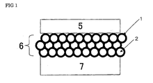
- FIG 1 is a schematic view showing the structure of the intermediate layer arranged in the membrane-electrode assembly of the invention.
- the intermediate layer comprises an ion conductor, the block copolymer as a main constituent of the ion conductor phase-separates into polymer block (A) having ion-conductive groups and polymer block (B) having no ion-conductive group, polymer block (A) having ion-conductive groups forms a continuous phase, and the contact part(s) of the intermediate layer(s) with the polymer electrolyte membrane and the contact part(s) of the intermediate layer(s) with the electrode catalyst layer(s) are comprised or composed of polymer block (A) having ion-conductive groups.
- the block copolymer used in the invention is such a copolymer that it comprises polymer block (A) having ion-conductive groups and polymer block (B) having no ion-conductive group, and both blocks mutually phase-separate.
- copolymer there can be used copolymers described in WO 2006/068279 A1 .
- the block copolymer used in the invention is described in detail below.
- aromatic vinyl compounds conjugated dienes having 4 to 8 carbon atoms (1,3-butadiene, isoprene, etc.), alkenes having 2 to 8 carbon atoms (ethylene, propylene, isobutylene, etc.), (meth)acrylic esters (methyl (meth)acrylate, ethyl (meth)acrylate, butyl (meth)acrylate, etc.), vinyl esters (vinyl acetate, vinyl propionate, vinyl butyrate, vinyl pivalate, etc.); vinyl ethers (methyl vinyl ether, isobutyl vinyl ether, etc.), etc., but, in view of easiness of introduction of an ion-conductive group, aromatic vinyl compounds are preferred.
- aromatic vinyl compounds examples include styrene, ⁇ -methylstyrene, styrene wherein 1 to 3 hydrogen atom(s) bonded to the benzene ring is/are replaced with alkyl group(s) each having 1 to 4 carbon atoms (methyl group(s), ethyl group(s), n-propyl group(s), isopropyl group(s), n-butyl group(s), isobutyl group(s), tert-butyl group(s), etc.) (p-methylstyrene, etc.), vinylnaphthalene, vinylanthracene, vinylpyrene, vinylpyridine and so on.
- the aromatic vinyl compound unit is a styrene unit and/or an ⁇ -methylstyrene unit. It is also preferred in view of heightening stability against oxidation by hydrogen peroxide formed due to side reaction of electrode reaction and/or hydroxyl radicals derived from hydrogen peroxide that the aromatic vinyl compound unit has a structure having no tertiary carbon, and, specifically, is an ⁇ -methylstyrene unit.
- polymer block (A) can contain one or plural other monomer units.
- monomer units there can, for example, be mentioned conjugated diene units each having 4 to 8 carbon atoms (1,3-butadiene unit, isoprene unit, etc.), (meth)acrylic ester units (methyl (meth)acrylate unit, ethyl (meth)acrylate unit, butyl (meth)acrylate unit, etc.), alkene units each having 2 to 8 carbon atoms (ethylene unit, propylene unit, isobutene unit, etc.), etc.
- conjugated diene units each having 4 to 8 carbon atoms (1,3-butadiene unit, isoprene unit, etc.
- (meth)acrylic ester units methyl (meth)acrylate unit, ethyl (meth)acrylate unit, butyl (meth)acrylate unit, etc.
- alkene units each having 2 to 8 carbon atoms (ethylene unit, propylene unit, isobut
- the conjugated diene unit is preferably one wherein its 30 % by mol or more is hydrogenated, more preferably one wherein its 50 % by mol or more is hydrogenated and still more preferably one wherein its 80 % by mol or more is hydrogenated.
- the proportion of the aromatic vinyl compound unit in polymer block (A) is preferably 80 % by mass or more and more preferably 90 % by mass or more.
- the form of the copolymerization of the aromatic vinyl compound with the other monomer is preferably random copolymerization.
- the molecular weight of polymer block (A) in such a state that no ion-conductive group is introduced is appropriately chosen depending on the nature and state, desired performance, other polymer components, etc. of the ion conductor.
- the molecular weight is large, there is a tendency that, due to rise of viscosity, it becomes difficult to obtain an aqueous dispersion of the block copolymer having a uniform average particle size, and, further, the dynamic characteristics such as tensile strength of the ion conductor becomes higher, and when the molecular weight is small, there is a tendency that it becomes difficult that the block copolymer constituting the ion conductor forms phase separation structure, and, thus, it is important to appropriately choose the molecular weight in accordance with necessary performance.
- the molecular weight is preferably chosen between 100 and 1,000,000, and more preferably chosen between 1,000 and 100,000, as number average molecular weight in terms of polystyrene.
- the block copolymer has, besides polymer block (A), polymer block (B) having no ion-conductive group. If an ion-conductive group is introduced into polymer block (A) in a high content, water resistance is heightened by having polymer block (B), and it is possible to prevent the ion conductor binder from flowing out during power generation.
- Polymer block (B) is not particularly restricted so long as it phase-separates from polymer block (A) and has water resistance, but it is preferred that polymer block (B) is a rubber-like polymer block (B1).
- polymer block (B) has flexible structure, the block copolymer takes on elasticity and becomes flexible as a whole, and in preparation of membrane-electrode assemblies and polymer electrolyte fuel cells, moldability (assembling properties, bonding properties, fastening properties, etc.) is improved.
- Such flexible polymer block (B1) is a so-called rubber-like polymer block whose glass transition point or softening point is 50°C or less, preferably 20°C or less, more preferably 10°C or less.
- repeating unit constituting polymer block (B1) there can be mentioned conjugated diene units each having 4 to 8 carbon atoms (1,3-butadiene unit, isoprene unit, etc.), alkene units each having 2 to 8 carbon atoms (isobutylene unit, etc.), etc. Monomers giving these units can be used alone or in a combination of two or more. When two or more are copolymerized, the form of the copolymerization can be random copolymerization, block copolymerization, graft copolymerization or tapered copolymerization.
- any of them can be used in the (co)polymerization, and in the case of a conjugated diene either of 1,2-bond and 1,4-bond can be used in the (co)polymerization, and so long as the glass transition point or softening point is 50°C or less, there is no particular restriction on the proportion between 1,2-bond and 1,4-bond.
- the repeating units constituting polymer block (B1) have a carbon-carbon double bond as in conjugated diene units, it is preferred that 30 % by mol or more of the carbon-carbon double bonds are hydrogenated, it is further preferred that 50 % by mol or more thereof are hydrogenated, and it is still further preferred that 80 % by mol or more thereof are hydrogenated, in view of enhancement of the power generation performance, heat deterioration resistance, etc. of membrane-electrode assemblies using the intermediate layer of the invention.
- the hydrogenation proportion of the carbon-carbon double bonds can be calculated according to a method generally used, for example, a method of measuring iodine value, 1 H-NMR measurement, or the like.
- Polymer block (B1) can contain, besides the above monomer unit(s) [conjugated diene unit(s) having 4 to 8 carbon atoms (1,3-butadiene unit(s), isoprene unit(s), etc.), alkene unit(s) having 2 to 8 carbon atoms (isobutylene unit(s), etc.), etc.], another monomer unit, for example a unit of an aromatic vinyl compound such as styrene or vinylnaphthalene or a halogen-containing vinyl compound such as vinyl chloride, so long as it does not spoil the purposes of polymer block (B1) of giving elasticity to the block copolymer.
- monomer unit(s) conjuggated diene unit(s) having 4 to 8 carbon atoms (1,3-butadiene unit(s), isoprene unit(s), etc.
- alkene unit(s) having 2 to 8 carbon atoms isobutylene unit(s), etc.
- another monomer unit for example
- the form of the copolymerization of the above monomer unit(s) with another monomer unit is preferably random copolymerization.
- the proportion of the above monomer unit(s) [conjugated diene unit(s) having 4 to 8 carbon atoms (1,3-butadiene unit(s), isoprene unit(s), etc.), alkene unit(s) having 2 to 8 carbon atoms (isobutylene unit(s), etc.), etc.] in polymer block (B1) is preferably 50 % by mass or more, more preferably 70 % by mass or more, still more preferably 90 % by mass or more, based on the total of the above monomer unit(s) and another monomer unit.
- polymer block (B1) has no ion-conductive group is that it substantially has no ion-conductive group, and, if a trace amount of ion-conductive groups are incorporated into polymer block (B1) in the course of preparation of the block copolymer, it is within the invention. This applies to polymer block (B2) described later.
- the mass ratio of polymer block (A) to polymer block (B1) in the copolymer is not particularly restricted so long as the water resistance of the ion conductor is fulfilled, and is preferably 95:5 to 5:95, more preferably 90:10 to 10:90 and still more preferably 50:50 to 10:90.
- the arrangement of polymer block (A) and polymer block (B1) in the block copolymer is not particularly restricted, and the block copolymer can be an A-B1 diblock copolymer, an A-B1-A triblock copolymer, a B1-A-B1 triblock copolymer, an A-B1-A-B1 tetrablock copolymer, an A-B1-A-B1-A pentablock copolymer, a B1-A-B1-A-B1 pentablock copolymer, etc.
- These block copolymers can be used alone or in a combination of two or more.
- the block copolymer used in the invention can contain, besides polymer block (A) and polymer block (B1), another polymer block (B2) which is different from these blocks, phase-separates from these blocks and has no ion-conductive group.
- polymer block (B) can comprise polymer block (B1) or comprise polymer block (B1) and polymer block (B2).
- As a repeating unit constituting polymer block (B2) there can be mentioned as a specific example an aromatic vinyl compound unit described in the explanation of polymer block (A).
- aromatic vinyl compound units constituting polymer block (B2) preferred is an aromatic vinyl compound unit which is hard to substitute with an ion-conductive group compared to the aromatic vinyl compound unit in polymer block (A), and, for example, when the aromatic vinyl compound unit(s) in polymer block (A) is/are a styrene unit and/or an ⁇ -methylstyrene unit, it is preferred that the aromatic vinyl compound unit constituting polymer block (B2) is a styrene unit wherein 1 to 3 hydrogen atom(s) bonded to the benzene ring is/are replaced with alkyl group(s) having 1 to 4 carbon atoms (e.g., t-butylstyrene unit).
- the block copolymer comprises polymer block (A), polymer block (B1) and polymer block (B2)
- the arrangement of these polymer blocks is not particularly restricted, and the block copolymer can be an A-B1-B2 triblock copolymer, an A-B1-B2-A tetrablock copolymer, an A-B1-A-B2 tetrablock copolymer, a B1-A-B1-B2 tetrablock copolymer, an A-B1-B2-B1 tetrablock copolymer, a B2-B1-B2-A tetrablock copolymer,an B2-A-B1-A-B2 pentablock copolymer, a B2-B1-A-B1-B2 pentablock copolymer, an A-B2-B1-B2-A pentablock copolymer, an A-B1-B2-B1-A pentablock copolymer, an A-B
- shell phases are easy to form by that there are polymer blocks (A) at both ends, for example, an arrangement wherein rubber-like polymer block (B1) is arranged at the center, polymer blocks (B2) are arranged adjacently to both sides thereof and polymer blocks (A) are arranged adjacently to both outsides of polymer block (B2), e.g. A-B2-B1-B2-A.
- polymer block (B2) When polymer block (B2) is used, swelling of the ion conductor is inhibited, and it is possible to reduce the possibility that the continuity of ion channels and, further, durability of the membrane-electrode assembly are spoiled due to the swelling of the ion conductor during power generation. Furthermore, in the step to form an intermediate layer by removing the aqueous dispersion medium from an aqueous dispersion wherein the block copolymer is dispersed, it is possible, by polymer block (B2), to reduce the possibility that the phase separation structure of the ion conductor which has been formed in the dispersion is changed.
- the proportion of polymer block (B2) in the block copolymer is preferably less than 75 % by mass, more preferably less than 70 % by mass and still more preferably less than 60 % by mass. Further, in view of making polymer block (B2) display the function as mentioned above, the proportion of polymer block (B2) in the block copolymer is preferably 10 % by mass or more, more preferably 20 % by mass or more and still more preferably 25 % by mass or more.
- the ratio by mass of the total of polymer block (A) and polymer block (B2) to polymer block (B1) is preferably 20:80 to 80:20, more preferably 25:75 to 75:25 and still more preferably 30:70 to 70:30 in view of performances needed, flexibility and elasticity and, further, from the viewpoint of giving good moldability in preparation of membrane-electrode assemblies and polymer electrolyte fuel cells.
- the number average molecular weight of the block copolymer used in the invention, in a state that ion-conductive groups are not introduced, is not particularly restricted, but, usually, is preferably 10,000 to 2,000,000, more preferably 15,000 to 1,000,000 and still more preferably 20,000 to 500,000 as number average molecular weight in terms of polystyrene.
- the block copolymer used in the invention has ion-conductive groups on polymer block (A).
- the ion includes a cation and an anion
- the cation includes a proton, etc.
- the anion includes a hydroxide ion, etc.
- the ion-conductive group either of a cation-conductive group and an anion-conductive group can be used, but the cation-conductive group is preferably used.
- the cation-conductive group is not particularly restricted so long as it is such a group that a membrane-electrode assembly prepared using the ion conductor can display sufficient cation conductivity, but a sulfonic acid group or a phosphonic acid group or their salts represented by -SO 3 M or -PO 3 HM wherein M represents a hydrogen atom, an ammonium ion or an alkali metal ion, can be used preferably.
- M represents a hydrogen atom, an ammonium ion or an alkali metal ion
- the alkali metal ion there can be mentioned a sodium ion, a potassium ion, a lithium ion, etc.
- a carboxyl group or a salt thereof can also be used.
- the anion-conductive group is not particularly restricted so long as it is such a group that a membrane-electrode assembly prepared using the ion conductor can display sufficient anion conductivity, and there can be mentioned groups as shown below.
- R 1 to R 3 represent respectively independently hydrogen atoms or alkyl groups having 1 to 8 carbon atoms
- R 4 to R 9 and R 11 represent respectively independently hydrogen atoms, methyl groups or ethyl groups
- R 10 represents a methyl group or an ethyl group
- m represents an integer of 2 to 6
- n represents 2 or 3.
- polyvalent groups bond polymer blocks (A) themselves among block copolymers or inside the block copolymer.
- the ion-conductive groups preferably exist at the side chains or free ends of the aromatic vinyl polymer block (A).
- the amount of the ion-conductive group introduced is appropriately selected depending on performances needed for the block copolymer obtained and the like, but, in order to display sufficient ion conductivity to use the block copolymer as an intermediate layer, usually, the amount of ion-conductive groups introduced is preferably such an amount that the ion exchange capacity of the block copolymer is 0.30 meq/g or more, and more preferably such an amount that it is 0.40 meq/g or more.
- the upper limit of the ion exchange capacity of the block copolymer there is no particular restriction, but, usually, it is preferred that the ion exchange capacity is 3 meq/g or less.
- the proportion of the monomer unit having an ion-conductive group in polymer block (A) is preferably 10 % by mol or more, more preferably 30 % by mol or more and still more preferably 50 % by mol or more.
- the form of copolymerization of the monomer unit having an ion-conductive group with other monomer unit(s) is preferably random copolymerization for preventing polymer block (A) from phase separating.
- the block copolymer used in the invention can be prepared according to the preparation process described in WO 2006/068279 A1 mentioned previously, or according to a similar process thereto.
- the block copolymer In the intermediate layer(s) arranged at the membrane-electrode bonding part(s) in the membrane-electrode assembly of the invention, particles themselves of the block copolymer come in contact with one another through polymer block (A) having ion-conductive groups, and, at the same time, the contact part(s) of the intermediate layer(s) with the electrolyte membrane and the contact part(s) of the intermediate layer(s) with the electrode catalyst layer(s) are comprised or composed of polymer block (A) having ion-conductive groups, and, in order to give such a structure, it is preferred that the block copolymer take such a core-shell structure that the inner layer (core phase) is polymer block (B) and the outer layer (shell phase) is polymer block (A).
- This core-shell structure is usually spherical.
- polymer block (A) having ion-conductive groups can form a continuous phase efficiently, the intermediate layer is excellent in inner ion conductivity, it is possible to form ion paths easily at the contact part(s) of the intermediate layer(s) with the electrolyte membrane and the contact part(s) of the intermediate layer(s) with the electrode catalyst layer(s), and, as a result, it is possible to reduce membrane-electrode interface resistance and enhance power generation efficiency.
- the ion conductor used in the invention mainly comprises the above -mentioned block copolymer.
- the ion conductor of the invention can contain, under such a condition that the effects of the invention are not spoiled, various additives, for example, softening agents, stabilizers, light stabilizers, antistatic agents, mold release agents, flame retardants, foaming agents, pigments, dyes, brighteners, carbon fiber, inorganic fillers, etc., alone respectively or in a combination of two or more.
- various additives for example, softening agents, stabilizers, light stabilizers, antistatic agents, mold release agents, flame retardants, foaming agents, pigments, dyes, brighteners, carbon fiber, inorganic fillers, etc.
- softening agent there can be mentioned petroleum softening agents such as paraffin-, naphthene- or aroma-process oils; paraffins; vegetable oil softening agents; plasticizers; etc.
- the stabilizers include phenol-type stabilizers, sulfur-type stabilizers, phosphorus-type stabilizers, and, as specific examples, there can be mentioned phenol-type stabilizers such as 2,6-di-t-butyl-p-cresol, pentaerythrityl tetrakis [3- (3,5-di-t-butyl-4-hydroxyphenyl)propionate], 1,3,5-trimethyl-2,4,6-tris(3,5-di-t-butyl-4-hydroxybenzyl)benzene, octadecyl-3-(3,5-di-t-butyl-4-hydroxyphenyl) propionate, triethylene glycol bis[3- (3-t-butyl-5-methyl-4-hydroxyphenyl)propionate], 2,4-bis(n-octylthio) -6- (4-hydroxy-3,5-di-t-butylanilino) -1,3,5-triazine, 2,2-
- inorganic fillers there can be mentioned talc, calcium carbonate, silica, glass fiber, mica, kaolin, titanium oxide, montmorillonite, alumina, etc.
- the content of the block copolymer in the ion conductor used in the invention is preferably 50 % by mass or more, more preferably 70 % by mass or more and further more preferably 90 % by mass or more, in view of ion conductivity.
- the block copolymer In the intermediate layer arranged at the membrane-electrode bonding part(s) in the membrane-electrode assembly of the invention, particles themselves of the block copolymer come in contact with one another through polymer block (A) having ion-conductive groups, and, at the same time, the contact part(s) of the intermediate layer(s) with the electrolyte membrane and the contact part(s) of the intermediate layer(s) with the electrode catalyst layer(s) are comprised or composed of polymer block (A) having ion-conductive groups, and, in order to give such a structure, it is preferred that the block copolymer take such a form that polymer block (B) having no ion-conductive group phase-separates toward the inside and polymer block (A) having ion-conductive groups phase-separates toward the outside (namely, core-shell structure).
- Methods of inducing such a form are not particularly restricted.
- a dispersion in this method an emulsion or a suspension is preferred, and the emulsion is further preferred.
- the particle size of the block copolymer in the dispersion in the method (1) is preferably 1 ⁇ m or less, more preferably 0.5 ⁇ m or less and still more preferably 0.1 ⁇ m or less.
- the particle size is 1 ⁇ m or less, reduction of membrane-electrode interface resistance is remarkable, and cell output can be enhanced, compared to cases of particle sizes larger than that.
- the lower limit of the particle size of the block copolymer in the dispersion is not particularly restricted, but, in view of adjusting it to a particle size necessary for that the block copolymer phase-separates into a phase having ion-conductive groups and a phase having no ion-conductive group, the particle size is preferably 10nm or more and more preferably 40nm or more.
- the particle size in the dispersion can be measured by methods generally used, for example, a dynamic light scattering method or the like.
- Processes of obtaining a dispersion of the block copolymer in the method (1) are not particularly restricted, and there can be mentioned a process of emulsifying the block copolymer in an aqueous dispersion medium, a process of obtaining such a dispersion by liquid phase polymerization such as emulsion polymerization or suspension polymerization, etc., but, the process of emulsifying the block copolymer is preferred.
- a direct emulsification method comprising dispersing a melt of the block copolymer into an aqueous dispersion medium at temperatures higher than the melting point of the block copolymer.
- the aqueous dispersion medium means water or a solvent mainly comprising water.
- a solution inversion emulsification method comprising dissolving the block copolymer in an organic solvent and then dispersing the solution in an aqueous dispersion medium.
- organic solvents used for dissolution of the block copolymer and organic solvents mixed with water used as a dispersion medium there can be exemplified alcohols such as methanol, ethanol, propanol and isopropanol; halogenated hydrocarbons such as methylene chloride; aromatic hydrocarbons such as toluene, xylene and benzene; straight-chain aliphatic hydrocarbons such as hexane and heptane; cyclic aliphatic hydrocarbons such as cyclohexane; ethers such as tetrahydrofuran; and further, acetonitrile, nitromethane, dimethyl sulfoxide, N-methylpyrrolidone, N,N-dimethylformamide, N,N-dimethylacetamide, etc.
- alcohols such as methanol, ethanol, propanol and isopropanol
- halogenated hydrocarbons such as methylene chloride
- solvents can be used each alone or in a combination of two or more.
- an organic solvent is used in dispersion of the copolymer, it is preferred to remove the organic solvent after the dispersion was made.
- the removal of the organic solvent can, for example, be made by utilization of azeotropy with water, using a reaction vessel equipped with a stirrer and a condenser, an extruder equipped with a vent, a rotary evaporator or the like.
- the removal of the organic solvent can be made either under atmospheric pressure or under reduced pressure.
- Dispersion of the block copolymer can be made using a vessel equipped with a stirring means.
- the stirring means is not particularly restricted, but, in view of generating large shearing force, turbine stirrers, colloid mills, homomixers and homogenizers are preferred.
- the dispersion can also be made using a line mixer equipped with a movable stirring apparatus, an immovable line mixer (Static Mixer, trade name, made by Noritake Co., Ltd.) or the like.
- a surfactant can be used as an emulsifier or dispersant, and there can be used nonionic surfactants, anionic surfactants, etc.
- the use amount of the surfactant is usually in the range of 0.1 to 40 parts by mass and preferably in the range of 0.1 to 20 parts by mass based on 100 parts by mass of the block copolymer used, but it is desirable to use it at a necessary minimum amount.
- nonionic surfactants there can, for example, be mentioned polyethylene glycol-type nonionic surfactants, polyhydric alcohol-type nonionic surfactants, etc.
- polyethylene glycol-type nonionic surfactants there can, for example, be mentioned ethylene oxide adducts of higher alcohols, ethylene oxide adducts of alkylphenols, ethylene oxide adducts of fatty acids, ethylene oxide adducts of polyhydric alcohol fatty acid esters, ethylene oxide adducts of higher alkylamines, ethylene oxide adducts of fatty acid amides, ethylene oxide adducts of fats and oils, ethylene oxide adducts of polypropylene glycols, etc.
- polyhydric alcohol-type nonionic surfactants there can, for example, be mentioned glycerol fatty acid esters, pentaerythritol fatty acid esters, sorbitol fatty acid esters, sorbitan fatty acid esters, sucrose fatty acid esters, polyhydric alcohol alkyl ethers, alkanolamine fatty acid amides, etc.
- anionic surfactants there can, for example, be mentioned primary higher fatty acid salts, secondary higher fatty acid salts, primary higher alcohol sulfate esters, secondary higher alcohol sulfate esters, primary higher alkylsulfonate salts, secondary higher alkylsulfonate salts, higher alkyldisulfonate salts, sulfonated higher fatty acid salts, alkoxysulfonyl-higher fatty acid salts, higher fatty acid ester-sulfonate salts, salts of sulfonated higher alcohol ethers, alkylbenzenesulfonate salts, alkylphenolsulfonate salts, alkylnaphthalenesulfonate salts, alkylbenzimidazolesulfonate salts, alkyl phosphate salts, salts of phosphonated alkyl ethers, salts of phosphonated alkyl allyl ethers, etc.
- surfactants can be used alone or in a combination of two or more.
- the membrane-electrode assembly of the invention is now described.
- preparation processes of a membrane-electrode assembly having intermediate layer(s) there is no particular restriction, and, for example, there can be used a process which comprises forming intermediate layer(s) on the surface(s) of an electrolyte membrane and bonding gas diffusion electrode(s) so that the intermediate layer(s) and the electrode catalyst layer(s) can be bonded; a process which comprises forming intermediate layer(s) on the surface(s) of the electrode catalyst layer(s) composing gas diffusion electrode(s) and bonding an electrolyte membrane so that the intermediate layer(s) and the electrolyte membrane can be bonded; a process which comprises forming intermediate layer(s) on the surface(s) of an electrolyte membrane, forming electrode catalyst layers on both sides of the electrolyte membrane and compression-bonding gas diffusion layers on the respective electrode catalyst layers by a hot press or the like; etc.
- processes for forming intermediate layer(s) on the surface(s) of the electrolyte membrane or the electrode catalyst layer(s) there is no particular restriction, and there can, for example, be mentioned a process which comprises removing the dispersion medium from the above-mentioned dispersion containing the block copolymer, and as processes for removal of the dispersion medium, there can be mentioned a process which comprises applying the dispersion onto the surface(s) of the electrolyte membrane or the electrode catalyst layer(s) and, at the same time or thereafter, evaporating the dispersion medium by air drying, drying by heating, drying under reduced pressure, drying in a stream of air or the like.
- a process which comprises forming an intermediate layer on a substrate film such as one made of polytetrafluoroethylene (PTFE) and removing the dispersion medium, transferring the intermediate layer on the substrate film onto the surface of the electrolyte membrane or the electrode catalyst layer by compression bonding, and peeling away the substrate film; a process which comprises applying the dispersion onto the surface of the electrode catalyst layer or the electrolyte membrane, and removing the dispersion medium seeping from its back; etc.
- the intermediate layer can be used on either or both of the membrane-electrode bonding parts.
- the polymer electrolyte membrane constituting the membrane-electrode assembly there can, for example, be used an electrolyte membrane comprising an existing perfluorocarbonsulfonic polymer such as "Nafion” (registered trade mark, made by Du Pont Co.) or "Gore-select” (registered trade mark, made by Gore Co.), an electrolyte membrane comprising a sulfonated polyether sulfone or a sulfonated polyether ketone, an electrolyte membrane comprising a polybenzimidazole impregnated with phosphoric acid or sulfuric acid, etc.
- an electrolyte membrane comprising an existing perfluorocarbonsulfonic polymer such as "Nafion" (registered trade mark, made by Du Pont Co.) or "Gore-select” (registered trade mark, made by Gore Co.), an electrolyte membrane comprising a sulfonated polyether sulf
- an electrolyte membrane of the block copolymer constituting the ion conductor it is also possible to make an electrolyte membrane of the block copolymer constituting the ion conductor to be used as an intermediate layer constituting the membrane-electrode assembly of the invention.
- an electrolyte membrane made of the same material as that of the block copolymer used in the intermediate layer constituting the membrane-electrode assembly of the invention it is preferred to use an electrolyte membrane made of the same material as that of the block copolymer used in the intermediate layer constituting the membrane-electrode assembly of the invention, and, namely, although a polymer used in the polymer electrolyte membrane and a block copolymer used in the intermediate layer may be the same or different, it is preferred that both of them fall within the definition of block copolymers used in the intermediate layer.
- the block copolymer used in the intermediate layer is used as a polymer electrolyte membrane and the block copolymer contains polymer block (B2)
- the block copolymer contains polymer block (B2)
- an electrode catalyst layer constituting the above-mentioned membrane-electrode assembly there is no particular restriction on preparation of an electrode catalyst layer constituting the above-mentioned membrane-electrode assembly, and known processes can be applied, and, for example, it is possible to form a composite of an electrode catalyst layer and the gas diffusion layer by applying a catalyst paste containing an ion-conductive binder onto a gas diffusion layer according to a printing method or a spraying method and drying it.
- the catalyst paste can be prepared by mixing and dispersing an ion-conductive binder and catalyst particles into a solvent such as water or an alcoholic solvent.
- a water repellent material such as polytetrafluoroethylene, polyhexafluoropropylene or a tetrafluoroethylene-hexafluoropropylene copolymer or the like in a small amount in such a range that the effects of the invention are not spoiled.
- a water repellent material it is possible to enhance water repellency of the resulting electrode catalyst layer and promptly discharge water or the like formed during power generation.
- the content of the ion-conductive binder in the catalyst paste can appropriately be determined so that the resulting electrode catalyst layer can have desired characteristics, but the content is preferably such that the mass of the ion-conductive binder is 0.1 to 3.0 times that of the catalyst metal, more preferably such that the mass of the ion-conductive binder is 0.3 to 2.0 times that of the catalyst metal, and still more preferably such that the mass of the ion-conductive binder is 0.5 to 1.5 times that of the catalyst metal.
- the content is preferably such that the mass of the ion-conductive binder is 0.1 times or more that of the catalyst metal, and in view of securing diffusion paths of reactants in the resulting electrode catalyst layer, the content is preferably such that the mass of the ion-conductive binder is 3.0 times or less that of the catalyst metal.
- the total concentration of solid matter such as the catalyst particles and the ion-conductive binder is preferably on the order of 5 to 50 % by mass.
- an ion-conductive binder comprised of an existing perfluorocarbonsulfonic acid-type polymer such as "Nafion” (registered trade mark, made by Dupont Co.) or "Gore-select” (registered trade mark, made by Gore Co.); an ion-conductive binder comprised of a sulfonated polyether sulfone or a sulfonated polyether ketone; an ion-conductive binder comprised of a polybenzimidazole impregnated with phosphoric acid or sulfuric acid; or the like.
- an existing perfluorocarbonsulfonic acid-type polymer such as "Nafion” (registered trade mark, made by Dupont Co.) or "Gore-select” (registered trade mark, made by Gore Co.)
- an ion-conductive binder comprised of a sulfonated polyether sulfone or a sulfonated
- an anion-conductive binder there can, for example, be used an anion-conductive binder obtained by reacting polychloromethylstyrene with a tertiary amine to give a quaternary ammonium salt and, if necessary, converting it to the form of a hydroxide; or the like. It is also possible to make an ion-conductive binder of the block copolymer constituting the ion conductor used in the invention. Such an ion-conductive binder can contain the same additive as in the aforementioned ion conductor, in the same amount.
- an ion-conductive binder made of the same material as that of the block copolymer used in the intermediate layer constituting the membrane-electrode assembly of the invention. Namely, although a polymer used in the ion conductive binder and the block copolymer used in the intermediate layer may be the same or different, but it is preferred that they both fall within the definition of the block copolymer used in the intermediate layer
- catalyst metal fine particles such as platinum black
- particles supporting a catalyst thereon wherein a catalyst metal is supported on an electrically conductive material there is no particular restriction, and there can be used catalyst metal fine particles such as platinum black, and particles supporting a catalyst thereon wherein a catalyst metal is supported on an electrically conductive material.
- the catalyst metal any metal can be used so long as it is a metal capable of promoting oxidation reaction of a fuel such as hydrogen or methanol and reduction reaction of oxygen, and there can, for example, be mentioned platinum, gold, silver, palladium, iridium, rhodium, ruthenium, iron, cobalt, nickel, chromium, tungsten, manganese, etc., and their alloys such as a platinum-ruthenium alloy. Among them, platinum or a platinum alloy is used in many cases.
- the particle size of a metal as the catalyst is, usually, 10 to 300 angstroms.
- any electrically conductive materials can be used, and there can, for example, be mentioned carbon materials.
- carbon materials there can, for example, be mentioned carbon blacks such as furnace black, channel black and acetylene black, activated carbon, graphite, etc. These can be used alone or as a mixture of two or more.
- the gas diffusion layer of the membrane-electrode assembly is comprised of a material having electrical conductivity and gas permeability, and as the material, there can, for example, be mentioned a porous material composed of carbon fiber such as carbon paper or carbon cloth. Such a material can be subjected to water repellent treatment for heightening water repellency.
- a process for making water repellent treatment there can, for example, be mentioned a process which comprises immersing the gas diffusion layer in a dispersion of a fluorine-type water repellent material such as polytetrafluoroethylene or the like, and heat drying the resulting gas diffusion layer in an oven or the like; or the like.
- a polymer electrolyte fuel cell By inserting a membrane-electrode assembly obtained by a process as mentioned above between electrically conductive separator materials having both of a role of separation of the electrode chamber and a role of paths for gas supply to the electrodes, a polymer electrolyte fuel cell can be obtained.
- the membrane-electrode assembly of the invention can be used as a membrane-electrode assembly for polymer electrolyte fuel cells such as a pure hydrogen one using hydrogen as the fuel gas, a methanol-reforming one using hydrogen obtained by reforming methanol, a natural gas-reforming one using hydrogen obtained by reforming natural gas, a gasoline-reforming one using hydrogen obtained by reforming gasoline and a direct methanol one wherein methanol is used directly.
- mSBmS poly ( ⁇ -methylstyrene)-b-polybutadiene-b-poly( ⁇ -methylstyrene) triblock copolymer
- the number average molecular weight (GPC measurement, in terms of polystyrene) of the resulting mSBmS was 76,000, and the amount of the 1,4-bond determined by 1 H-NMR measurement was 55 % and the content of the ⁇ -methylstyrene unit also determined by the 1 H-NMR measurement was 30.0 % by mass. Further, it was revealed by composition analysis through 1 H-NMR spectrum measurement that ⁇ -methylstyrene was not substantially copolymerized into the polybutadiene block.
- a solution of the synthesized mSBmS in cyclohexane was prepared, the solution was put in a pressure proof vessel whose atmosphere had sufficiently been replaced with nitrogen, and then, hydrogenation reaction was conducted at 80°C for 5 hours in an atmosphere of hydrogen using a Ni/A1 Ziegler hydrogenating catalyst to obtain a poly ( ⁇ -methylstyrene) -b-hydrogenated polybutadiene-b-poly ( ⁇ -methylstyrene) triblock copolymer (hereinafter abbreviated as mSEBmS).
- the hydrogenation proportion of the mSEBmS was calculated by 1 H-NMR spectrum measurement to be 99.6 %.
- a sulfonated mSEBmS was synthesized. Specifically, first, a sulfonating reagent was prepared by reacting 21.0 ml of acetic anhydride with 9.34 ml of sulfuric acid at 0°C in 41.8 ml of methylene chloride.
- tBSSIStBS poly (4-tert-butylstyrene)-b-polystyrene-b-polyisoprene-b-polystyrene-b-poly(4-tert-butylstyrene)
- the number average molecular weight (GPC measurement, in terms of polystyrene) of the obtained tBSSIStBS was 94,682, and the amount of the 1,4-bond, the content of the styrene unit and the content of the 4-tert-butylstyrene unit determined by 1 H-NMR measurement were 93.8 %, 17.6 % by mass and 42.9 % by mass, respectively.
- tBSSEPStBS poly (4-tert-butylstyrene)-b-polystyrene-b-hydrogenated polyisoprene-b-polystyrene-b-poly(4-tert-butylstyrene)
- tBSSEPStBS poly (4-tert-butylstyrene)-b-polystyrene-b-hydrogenated polyisoprene-b-polystyrene-b-poly(4-tert-butylstyrene)
- a sulfonated tBSSEPStBS was prepared. Specifically, first, a sulfonating reagent was prepared by reacting 19.2 ml of acetic anhydride with 8.6 ml of sulfuric acid at 0°C in 38.4 ml of methylene chloride. Separately, 100g of the block copolymer tBSSEPStBS obtained in Referential example 3 was vacuum dried for 1 hour in a glass-made reaction vessel equipped with a stirrer, the inside atmosphere of the reaction vessel was replaced with nitrogen, 840 ml of methylene chloride was added, and the mixture was stirred at 35°C for 4 hours to dissolve the block copolymer.
- the sulfonating reagent was gradually added dropwise thereto over a period of 20 minutes. After stirring at 35°C for 1 hour, the polymer solution was poured into 2L of distilled water under stirring to coagulate and deposit the polymer. The deposited solid matter was washed with distilled water of 90°C for 30 minutes, and then filtered. This operation of washing and filtration was repeated until the pH of the washings became unchanged, and the polymer after the final filtration was vacuum dried to obtain a sulfonated tBSSEPStBS.
- the ion exchange capacity of the sulfonated tBSSEPStBS was 0.50 meq/g.
- StBSItBSS polystyrene-poly(4-tert-butylstyrene)-b-polyisoprene-b-poly(4-tert-butylstyrene-b-polystyrene)
- StBSItBSS polystyrene-poly(4-tert-butylstyrene)-b-polyisoprene-b-poly(4-tert-butylstyrene-b-polystyrene)
- the number average molecular weight (GPC measurement, in terms of polystyrene) of the obtained StBSItBSS was 167,471, and the amount of the 1,4-bond, the content of the styrene unit and the content of the 4-tert-butylstyrene unit determined by 1 H-NMR measurement were 93.5 %, 9.6 % by mass and 62.2 % by mass, respectively.
- StBSEPtBSS polystyrene-b-poly (4-tert-butylstyrene)-b-hydrogenated polyisoprene-b-poly(4-tert-butylstyrene)-b-polystyrene.
- the hydrogenation proportion of the StBSEPtBSS was calculated by 1 H-NMR spectrum measurement to be 99.9 %.
- a sulfonated StBSEPtBSS was prepared. Specifically, first, a sulfonating reagent was prepared by reacting 14.8 ml of acetic anhydride with 6.62 ml of sulfuric acid at 0°C in 29.6 ml of methylene chloride. Separately, 20g of the block copolymer StBSEPtBSS obtained in Referential example 5 was vacuum dried for 1 hour in a glass-made reaction vessel equipped with a stirrer, the inside atmosphere of the reaction vessel was replaced with nitrogen, 262 ml of methylene chloride was added, and the mixture was stirred at room temperature for 4 hours to dissolve the block copolymer.
- the sulfonating reagent was gradually added dropwise thereto over a period of 20 minutes.
- the polymer solution was diluted with 50 ml of methylene chloride.
- the resulting polymer solution was poured into 2L of distilled water under stirring to coagulate and deposit the polymer.
- the deposited solid matter was washed with distilled water of 90°C for 30 minutes, and then filtered. This operation of washing and filtration was repeated until the pH of the washings became unchanged, and the polymer after the final filtration was vacuum dried to obtain a sulfonated StBSEPtBSS.
- the ion exchange capacity of the sulfonated StBSEPtBSS was 0.86 meq/g.
- the measurement of ion exchange capacitiy was made according to the following process.
- test membrane A An electrolyte membrane of thickness 50 ⁇ m and size 9 cmx9cm (hereinafter referred to as test membrane A) was prepared by a known process from the sulfonated mSEBmS obtained in Referential example 2.
- a gas diffusion electrode was prepared by mixing a dispersion of perfluorocarbonsulfonic acid made by Dupont Co. as an electrolyte with a catalyst to prepare a catalyst paste wherein the catalyst was uniformly dispersed, applying the catalyst paste uniformly onto one side of water repellent treated carbon paper, leaving alone the resulting carbon paper at room temperature for several hours, and drying it at 115°C for 30 minutes.
- the catalyst for the anode was used Pt-Ru supported on carbon made by Tanaka Kikinzoku Kogyo Co., Ltd. (TEC61E54), and as the catalyst for the cathode was used Pt supported on carbon made by Tanaka Kikinzoku Kogyo Co., Ltd. (TEC10E50E).
- the prepared gas diffusion electrodes had the following compositions respectively: anode; Pt 1.00 mg/cm 2 , Ru 0.77 mg/cm 2 , polymer 1.57 mg/cm 2 ; cathode; Pt 1.00 mg/cm 2 , polymer 1.20 mg/cm 2 .
- An intermediate layer was formed by spray applying and drying the dispersion obtained in Example 1(3) onto both sides of the test membrane A, and a membrane-electrode assembly was prepared by sticking together the gas diffusion electrodes obtained in Example 1(5) (5 cm ⁇ 5cm) and the test membrane A on which the intermediate layers was formed.
- test membrane B An electrolyte membrane of thickness 50 ⁇ m and size 9 cmx9cm (hereinafter referred to as test membrane B) was prepared by a known process from the sulfonated tBSSEPStBS obtained in Referential example 4.
- a membrane-electrode assembly was prepared in the same way as in Example 1(6) except that the test membrane B was used.
- Example 1(2) The aqueous dispersion obtained in Example 1(2) was treated by a high pressure homogenizer (Nanomizer mark II made by Yoshida Kikai Kogyo Co., Ltd.) to obtain an aqueous dispersion of the sulfonated StBSEPtBSS having an average particle size of about 85 nm.
- a high pressure homogenizer Nenomizer mark II made by Yoshida Kikai Kogyo Co., Ltd.
- An intermediate layer was formed by spray applying the dispersion obtained in Example 3(1) onto both sides of the test membrane A, and a membrane-electrode assembly was prepared by sticking together the gas diffusion electrode obtained in Example 1(5) (5 cm ⁇ 5cm) and the test membrane A on which the intermediate layers were formed.
- a membrane-electrode assembly was prepared in the same way as in Example 3(2) except that the test membrane B was used.
- Example 1(2) The aqueous dispersion obtained in Example 1(2) was treated by a high pressure homogenizer (Nanomizer mark II made by Yoshida Kikai Kogyo Co., Ltd.) to obtain an aqueous dispersion of the sulfonated StBSEPtBSS having an average particle size of about 117 nm.
- a high pressure homogenizer Nenomizer mark II made by Yoshida Kikai Kogyo Co., Ltd.
- An intermediate layer was formed by spray applying the dispersion obtained in Example 5(1) onto both sides of the test membrane A, and a membrane-electrode assembly was prepared by sticking together the gas diffusion electrodes obtained in Example 1(5) (5 cm ⁇ 5cm) and the test membrane A on which the intermediate layers were formed.
- a membrane-electrode assembly was prepared in the same way as in Example 5(2) except that the test membrane B was used.
- An intermediate layer was formed by spray applying the dispersion obtained in Example 5(1) onto the surface of the electrode catalyst layer of each of the gas diffusion electrodes obtained in Example 1(5), and a membrane-electrode assembly was prepared by sticking together the gas diffusion electrodes (5 cm ⁇ 5cm) on each of which the intermediate layer was formed and the test membrane A.
- a membrane-electrode assembly was prepared in the same way as in Example 7 except that the test membrane B was used.
- a membrane-electrode assembly was prepared by sticking together the test membrane A and the gas diffusion electrodes (5 cm ⁇ 5cm) obtained in Example 1(5).
- a membrane-electrode assembly was prepared in the same way as in Comparative example 1 except that the test membrane B was used.
- a membrane-electrode assembly was prepared by sticking together through hot pressing (130°C, 20 kgf/cm 2 , 8 min) the test membrane A and the gas diffusion electrodes (5 cm ⁇ 5cm) obtained in Example 1(5).
- a membrane-electrode assembly was prepared in the same way as in Comparative example 3 except that the test membrane B was used.
- An intermediate layer was formed by spray applying the dispersion of perfluorocarbonsulfonic acid made by Dupont Co., which dispersion was used in Example 1(5), onto both surfaces of the test membrane A, and a membrane-electrode assembly was prepared by sticking together through hot pressing (130°C, 20 kgf/cm 2 , 8 min) the gas diffusion electrodes (5 cm ⁇ 5cm) obtained in Example 1(5) and the test membrane A on which the intermediate layers were formed
- An intermediate layer was formed by spray applying the dispersion of perfluorocarbonsulfonic acid made by Dupont Co., which dispersion was used in Example 1(5), onto the surface of the electrode catalyst layer of each of the gas diffusion electrodes obtained in Example 1(5), and a membrane-electrode assembly was prepared by sticking together through hot pressing (130°C, 20 kgf/cm 2 , 8 min) the gas diffusion electrodes (5 cm ⁇ 5cm) on each of which the intermediate layer was formed and the test membrane A.
- An intermediate layer was formed by spray applying a dispersion of the sulfonated mSEBmS in tetrahydrofuran onto the surface of the electrode catalyst layer of each of the gas diffusion electrodes obtained in Example 1(5), and a membrane-electrode assembly was prepared by sticking together the gas diffusion electrodes (5 cm ⁇ 5cm) on each of which the intermediate layer was formed and the test membrane A.
- An intermediate layer was formed by spray applying a mixture liquid prepared by mixing the dispersion of perfluorocarbonsulfonic acid made by Dupont Co., which dispersion was used in Example 1(5), with carbon black (Valcan XC72) so that the mass ratio of the perfluorocarbonsulfonic acid / the carbon black could be 50/50, onto the surface of the electrode catalyst layer of each of the gas diffusion electrodes obtained in Example 1(5), and a membrane-electrode assembly was prepared by sticking together through hot pressing (130°C, 20 kgf/cm 2 , 8 min) the gas diffusion electrodes (5 cm ⁇ 5cm) on each of which the intermediate layer was formed and the test membrane A.
- An intermediate layer was formed by spray applying a mixture liquid prepared by mixing the sulfonated mSEBmS obtained in Referential example 2 with carbon black (Valcan XC72) so that the mass ratio of the sulfonated mSEBmS / the carbon black could be 50/50, onto the surface of the electrode catalyst layer of each of the gas diffusion electrodes obtained in Example 1(5), and a membrane-electrode assembly was prepared by sticking together the gas diffusion electrodes (5 cm ⁇ 5cm) on each of which the intermediate layer was formed and the test membrane A.
- each membrane cut into a size of 1 cm ⁇ 4 cm was put between 4 platinum wires to prepare a measurement cell.
- the measurement cell was immersed in water of a temperature of 40°C, and ion conductivity was measured by an alternative current 4 terminal method in the direction of the membrane surface.
- Each of the membrane-electrode assemblies prepared in Examples 1 to 8 and Comparative examples 1 to 6 was put between two sheets of electrically conductive separators also having a role of paths for gas supply, the resulting composite was put between two electric current-collecting sheets, and the resulting composite was put between two clamping sheets to assemble a single cell for polymer electrolyte fuel cells.
- a gasket was placed between each membrane-electrode assembly and each separator for preventing gas leak from a difference in level corresponding to the thickness of the electrode.
- As the fuel an aqueous 1 mol/L MeOH solution was used, and as the oxidizing agent, oxygen humidified by a bubbler of 60°C was used.
- Test conditions were set as follows, and electric resistance was evaluated after power generation was made for 2 hours under the condition of an electric current value of 50 mA/cm 2 : the test conditions; anode flow rate: 1 ml/min, cathode flow rate: 175 ml/min, cell temperature: 40°C.
- the electric resistance was measured under the condition of an electric current value of 50 mA/cm 2 by an electric current breaking method.
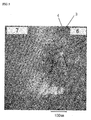
- Electron microscope photographs at the section of the membrane-electrode assembly obtained in Example 3 are shown in FIG 2 and FIG 3 .
- the membrane-electrode assembly obtained in Example 3 was observed in phase separation structure by selectively dyeing the sulfonic acid groups of the electrolyte materials, which constitute the membrane-electrode assembly, using lead acetate.
- the block copolymer in the intermediate layer forms a core-shell structure wherein the phase having ion-conductive groups is a shell phase and the phase having no ion-conductive group is a core phase.
- the shell phase in the core-shell structure forms continuous ion paths, and such a structure was clearly shown that both of the bonding part between the intermediate layer and the electrolyte membrane and the bonding part between the intermediate layer and the electrode catalyst layer are formed by the shell phase.
- the ion conductivities of the test membrane A and the test membrane B used in Examples 1 to 8 and Comparative examples 1 to 6 were 0.024 S/cm and 0.017 S/cm, respectively.
- Examples 1 to 8 and Comparative examples 1 to 6 the electric resistances of the single cells at 50 mA/cm 2 were measured, and the results are shown in Table 1.
- Table 1 Electrolyte membrane Intermediate layers Process of forming intermediate layers Condition of hot pressing Electric resistance of cell Exam. 1 Test membrane A Average particle size 59 nm Formed on the surfaces of the membrane No pressing 45m ⁇ Exam. 2 Test membrane B 41m ⁇ Exam. 3 Test membrane A Average particle size 85 nm Formed on the surfaces of the membrane No pressing 37m ⁇ Exam. 4 Test membrane B 29m ⁇ Exam.
- Example 1 From the tests of Example 1, Example 3, Example 5, Example 7, Comparative example 1 and Comparative example 3 wherein the test membrane A was used, the effect of introduction of the intermediate layers of the invention was shown. Likewise, also from the tests of Example 2, Example 4, Example 6, Example 8, Comparative example 2 and Comparative example 4 wherein the test membrane B was used, the effect of the invention was shown.
Landscapes
- Chemical & Material Sciences (AREA)
- General Chemical & Material Sciences (AREA)
- Electrochemistry (AREA)
- Chemical Kinetics & Catalysis (AREA)
- Sustainable Development (AREA)
- Sustainable Energy (AREA)
- Life Sciences & Earth Sciences (AREA)
- Manufacturing & Machinery (AREA)
- Engineering & Computer Science (AREA)
- Composite Materials (AREA)
- Crystallography & Structural Chemistry (AREA)
- Inert Electrodes (AREA)
- Fuel Cell (AREA)
- Manufacture Of Macromolecular Shaped Articles (AREA)
- Graft Or Block Polymers (AREA)
Claims (6)
- Membran-Elektrode-Anordnung für Polymerelektrolytbrennstoffzellen, umfassend eine Polymerelektrolytmembran und zwei Gasdiffusionselektroden, welche an die Membran gebunden sind, so daß die Membran zwischen diesen sein kann, wobei in der Anordnung jede Gasdiffusionselektrode eine Elektrodenkatalysatorschicht und eine Gasdiffusionsschicht umfasst, wobei (eine) Zwischenschicht(en), welche ein lonenleiter ist bzw. sind, zwischen mindestens einer der Elektrodenkatalysatorschichten und der Polymerelektrolytmembran angeordnet ist bzw. sind, wobei der Ionenleiter hauptsächlich ein Blockcopolymer, umfassend einen Polymerblock (A) mit ionenleitfähigen Gruppen und einen Polymerblock (B) mit nicht-ionenleitfähigen Gruppen, umfaßt, wobei beide Polymerblöcke voneinander phasensepariert sind, wobei der Polymerblock (A) ein Polymerblock ist, umfassend als eine wiederkehrende Einheit eine Styroleinheit und/oder eine α-Methylstyroleinheit, der Polymerblock (B) einen Polymerblock (B1) oder einen Polymerblock (B1) und einen Polymerblock (B2), phasensepariert von Polymerblock (A) und Polymerblock (B1), umfaßt, wobei der Polymerblock (B1) ein Polymerblock ist, umfassend als eine wiederkehrende Einheit mindestens eine Einheit, ausgewählt aus der Gruppe, bestehend aus einer Alkeneinheit mit 2 bis 8 Kohlenstoffatomen, einer konjugierten Dieneinheit mit 4 bis 8 Kohlenstoffatomen und einer konjugierten Dieneinheit mit 4 bis 8 Kohlenstoffatomen, worin in der Einheit ein Teil oder sämtliche Kohlenstoff-Kohlenstoff-Doppelbindungen hydriert sind, wobei Polymerblock (B2) ein Polymerblock ist, umfassend als eine wiederkehrende Einheit eine Styroleinheit, wobei ein bis drei Wasserstoffatom(e), gebunden an den Benzolring, durch Alkylgruppe(n) mit eins bis vier Kohlenstoffatomen ersetzt ist/sind, wobei der Anteil der Styroleinheit und/oder der α-Methylstryroleinheit in Polymerblock (A) 80 Masse-% oder mehr beträgt, wobei der Anteil der vorstehenden wiederkehrenden Einheit in Polymerblock (B1) 70 Masse-% oder mehr, bezogen auf die Gesamtheit der wiederkehrenden Einheit und einer weiteren Monomereinheit, ausgewählt aus einer Styroleinheit, einer Vinylnaphthalineinheit und einer Vinylchlorideinheit, beträgt, wobei der Anteil des Polymerblocks (B2) in dem Blockcopolymer 10 Masse-% oder mehr, aber weniger als 75 Masse-% beträgt, wobei das Blockcopolymer eine Kern-Schale-Struktur einnimmt, wobei Polymerblock (A) mit ionenleitfähigen Gruppen eine Schalenphase ist und Polymer-block (B) mit nicht-ionenleitfähigen Gruppen eine Kernphase ist, wobei Polymerblock (A) eine kontinuierliche Phase bildet, wobei die Kontaktstelle(n) der Zwischenschicht(en) mit der Polymerelektrolytmembran und die Kontaktstelle(n) der Zwischenschicht(en) mit der bzw. den Elektrodenkatalysatorschicht(en) Polymerblock (A) mit ionenleitfähigen Gruppen umfassen.
- Membran-Elektrode-Anordnung gemäß Anspruch 1, wobei das Blockcopolymer eine derartige Struktur aufweist, daß Polymerblock (A) an beiden Enden angeordnet ist.
- Membran-Elektrode-Einheit gemäß Anspruch 2, wobei das Blockcopolymer eine derartige Struktur aufweist, daß Polymerblock (B1) in dem Zentrum angeordnet ist, wobei der Polymerblock (B2) angrenzend an jede Seite davon angeordnet ist, und Polymerblock (A) angrenzend an jede äußere Seite des Polymerblocks (B2) angeordnet ist.
- Membran-Elektrode-Anordnung gemäß einem der Ansprüche 1 bis 3, wobei die ionenleitfähige Gruppe eine kationenleitfähige Gruppe, ausgewählt aus einer Sulfonsäuregruppe und einer Phosphorsäuregruppe und Alkalimetallsalzen und Ammoniumsalzen von diesen, ist.
- Membran-Elektrode-Anordnung gemäß einem der Ansprüche 1 bis 4, wobei der lonenleiter einer ist, erhalten durch Entfernen des wässrigen Dispersionsmediums von einer Dispersion, wobei das Blockcopolymer und optionale verschiedene Additive in einem wässrigen Dispersionsmedium dispergiert sind, so daß die Teilchengröße des Blockcopolymers 1 µm oder weniger sein kann.
- Polymerelektrolytbrennstoffzelle unter Verwendung der Membran-Elektrode-Anordnung gemäß einem der Ansprüche 1 bis 5.
Applications Claiming Priority (2)
| Application Number | Priority Date | Filing Date | Title |
|---|---|---|---|
| JP2008026626 | 2008-02-06 | ||
| PCT/JP2009/051355 WO2009098982A1 (ja) | 2008-02-06 | 2009-01-28 | 膜-電極接合体及び固体高分子型燃料電池 |
Publications (3)
| Publication Number | Publication Date |
|---|---|
| EP2242137A1 EP2242137A1 (de) | 2010-10-20 |
| EP2242137A4 EP2242137A4 (de) | 2012-01-25 |
| EP2242137B1 true EP2242137B1 (de) | 2014-12-03 |
Family
ID=40952059
Family Applications (1)
| Application Number | Title | Priority Date | Filing Date |
|---|---|---|---|
| EP09708609.4A Not-in-force EP2242137B1 (de) | 2008-02-06 | 2009-01-28 | Membranelektrodenbaugruppe und festpolymer-elektrolyt-brennstoffzelle |
Country Status (6)
| Country | Link |
|---|---|
| US (1) | US8263286B2 (de) |
| EP (1) | EP2242137B1 (de) |
| JP (1) | JP5501771B2 (de) |
| KR (1) | KR101556425B1 (de) |
| CN (1) | CN101939870B (de) |
| WO (1) | WO2009098982A1 (de) |
Cited By (2)
| Publication number | Priority date | Publication date | Assignee | Title |
|---|---|---|---|---|
| US9988500B2 (en) | 2014-04-02 | 2018-06-05 | Kraton Polymers U.S. Llc | Process for the preparation of an aqueous emulsion of a midblock sulfonated block copolymer |
| US10017611B2 (en) | 2014-04-02 | 2018-07-10 | Kraton Polymers U.S. Llc | Process for the preparation of an aqueous emulsion of a midblock sulfonated block copolymer |
Families Citing this family (14)
| Publication number | Priority date | Publication date | Assignee | Title |
|---|---|---|---|---|
| WO2011065460A1 (ja) * | 2009-11-30 | 2011-06-03 | 株式会社クラレ | 高分子電解質、高分子電解質膜、膜-電極接合体及び固体高分子型燃料電池 |
| DE102010056133B4 (de) | 2010-05-22 | 2023-02-16 | Audi Ag | Verfahren zur Herstellung von Elektrodenmaterial mit ein oder mehreren Katalysatorschichten oder funktionellen Schichten für eine PEM-Brennstoffzelle |
| KR101173867B1 (ko) | 2010-10-28 | 2012-08-14 | 삼성에스디아이 주식회사 | 리튬 이차 전지 |
| JPWO2013031634A1 (ja) * | 2011-08-31 | 2015-03-23 | 株式会社クラレ | ブロック共重合体、高分子電解質膜、膜−電極接合体及び固体高分子型燃料電池 |
| WO2013046380A1 (ja) * | 2011-09-28 | 2013-04-04 | 株式会社エクォス・リサーチ | 燃料電池の反応層の観察方法 |
| CN103165915B (zh) * | 2011-12-16 | 2016-05-11 | 中国科学院大连化学物理研究所 | 一种有效降低燃料电池Pt担量的催化层结构 |
| US9583767B2 (en) * | 2012-01-05 | 2017-02-28 | GM Global Technology Operations LLC | Methods for making battery electrode systems |
| WO2014043083A2 (en) * | 2012-09-12 | 2014-03-20 | Drexel University | Polymerized ionic liquid block copolymers as battery membranes |
| CN103490079B (zh) * | 2013-09-09 | 2015-10-28 | 清华大学 | 一种絮状表面聚苯并咪唑膜电极的制备方法 |
| US10047477B2 (en) | 2014-04-02 | 2018-08-14 | Kraton Polymers U.S. Llc | Textile coating composition |
| KR102592691B1 (ko) * | 2015-04-03 | 2023-10-24 | 삼성전자주식회사 | 리튬이차전지용 전해질 및 이를 포함하는 리튬이차전지 |
| EP3076470B1 (de) | 2015-04-03 | 2019-10-16 | Samsung Electronics Co., Ltd. | Lithiumsekundärbatterie |
| CN106887622B (zh) * | 2017-03-24 | 2020-01-07 | 厦门大学 | 含氟单离子导体聚合物电解质及其制备方法与应用 |
| CN113302219B (zh) * | 2019-01-30 | 2023-08-22 | 日本瑞翁株式会社 | 非水系二次电池电极用粘结剂组合物、非水系二次电池电极用浆料组合物、非水系二次电池用电极、以及非水系二次电池 |
Family Cites Families (18)
| Publication number | Priority date | Publication date | Assignee | Title |
|---|---|---|---|---|
| JPH0864221A (ja) | 1994-08-26 | 1996-03-08 | Sanyo Electric Co Ltd | 電極・高分子電解質接合体 |
| US7255954B2 (en) * | 1998-08-27 | 2007-08-14 | Cabot Corporation | Energy devices |
| JP2000195527A (ja) | 1998-12-25 | 2000-07-14 | Toshiba Corp | 燃料電池 |
| EP1352940B1 (de) | 2000-11-20 | 2009-04-08 | Kuraray Co., Ltd. | Druckempfindlicher klebstoff und blockpolymer für die verwendung darin |
| JP3921997B2 (ja) * | 2001-11-01 | 2007-05-30 | 宇部興産株式会社 | イオン伝導膜 |
| KR101149690B1 (ko) | 2003-12-09 | 2012-05-23 | 제이에스알 가부시끼가이샤 | 양성자 전도막 및 그의 제조 방법 |
| JP2005190749A (ja) | 2003-12-25 | 2005-07-14 | Nissan Motor Co Ltd | 燃料電池用膜電極接合体及びそれを用いた固体高分子形燃料電池 |
| CN100352091C (zh) * | 2004-11-03 | 2007-11-28 | 比亚迪股份有限公司 | 具有一体化结构的燃料电池膜电极的制备方法 |
| JP2006202737A (ja) * | 2004-12-20 | 2006-08-03 | Kuraray Co Ltd | イオン伝導性バインダー、膜−電極接合体及び燃料電池 |
| KR101261074B1 (ko) * | 2004-12-20 | 2013-05-06 | 가부시키가이샤 구라레 | 이온 전도성 바인더, 막 전극 접합체 및 연료 전지 |
| JP2006210326A (ja) | 2004-12-27 | 2006-08-10 | Kuraray Co Ltd | 固体高分子型燃料電池用高分子電解質膜、膜−電極接合体及び燃料電池 |
| US7887944B2 (en) * | 2005-12-21 | 2011-02-15 | General Electric Company | Integrated membrane electrode assembly and method related thereto |
| JP2007194048A (ja) * | 2006-01-18 | 2007-08-02 | Kuraray Co Ltd | イオン伝導性バインダー、膜−電極接合体及び燃料電池 |
| WO2007086309A1 (ja) * | 2006-01-26 | 2007-08-02 | Kuraray Co., Ltd. | 固体高分子型燃料電池用電解質積層膜、膜-電極接合体及び燃料電池 |
| WO2007094185A1 (ja) | 2006-02-13 | 2007-08-23 | Kuraray Co., Ltd. | 高分子電解質膜、膜-電極接合体及び固体高分子型燃料電池 |
| JP5191139B2 (ja) | 2006-02-24 | 2013-04-24 | 株式会社クラレ | 高分子電解質、高分子電解質膜、膜−電極接合体及び固体高分子型燃料電池 |
| JP4889006B2 (ja) * | 2006-05-08 | 2012-02-29 | 富士通株式会社 | 触媒電極、膜電極接合体及び固体高分子型燃料電池 |
| CN101652887B (zh) | 2007-02-07 | 2012-08-22 | 株式会社可乐丽 | 催化剂层、其制备方法、使用所述催化剂层的膜电极组件和固体聚合物燃料电池 |
-
2009
- 2009-01-28 JP JP2009552443A patent/JP5501771B2/ja not_active Expired - Fee Related
- 2009-01-28 WO PCT/JP2009/051355 patent/WO2009098982A1/ja not_active Ceased
- 2009-01-28 EP EP09708609.4A patent/EP2242137B1/de not_active Not-in-force
- 2009-01-28 US US12/812,901 patent/US8263286B2/en not_active Expired - Fee Related
- 2009-01-28 CN CN2009801043711A patent/CN101939870B/zh not_active Expired - Fee Related
- 2009-01-28 KR KR1020107019472A patent/KR101556425B1/ko not_active Expired - Fee Related
Cited By (2)
| Publication number | Priority date | Publication date | Assignee | Title |
|---|---|---|---|---|
| US9988500B2 (en) | 2014-04-02 | 2018-06-05 | Kraton Polymers U.S. Llc | Process for the preparation of an aqueous emulsion of a midblock sulfonated block copolymer |
| US10017611B2 (en) | 2014-04-02 | 2018-07-10 | Kraton Polymers U.S. Llc | Process for the preparation of an aqueous emulsion of a midblock sulfonated block copolymer |
Also Published As
| Publication number | Publication date |
|---|---|
| CN101939870B (zh) | 2013-11-13 |
| US8263286B2 (en) | 2012-09-11 |
| EP2242137A1 (de) | 2010-10-20 |
| JPWO2009098982A1 (ja) | 2011-05-26 |
| WO2009098982A1 (ja) | 2009-08-13 |
| KR20100103889A (ko) | 2010-09-28 |
| CN101939870A (zh) | 2011-01-05 |
| KR101556425B1 (ko) | 2015-10-01 |
| US20100310965A1 (en) | 2010-12-09 |
| EP2242137A4 (de) | 2012-01-25 |
| JP5501771B2 (ja) | 2014-05-28 |
Similar Documents
| Publication | Publication Date | Title |
|---|---|---|
| EP2242137B1 (de) | Membranelektrodenbaugruppe und festpolymer-elektrolyt-brennstoffzelle | |
| US8420276B2 (en) | Catalyst layer and preparation process thereof, and membrane-electrode assembly and polymer electrolyte fuel cell using the catalyst layer | |
| EP1986257B1 (de) | Polyelektrolytfilm, filmelektrodenbaugruppe und brennstoffzelle des festpolymertyps | |
| EP1978584B1 (de) | Elektrolyt-mehrschichtmembran für eine festpolymer-brennstoffzelle, membranelektrodenbaugruppe und brennstoffzelle | |
| EP1852928B1 (de) | Ionenleitfähiger binder, membran-elektroden-baugruppe und brennstoffzelle | |
| US20100159353A1 (en) | Polymer electrolyte, polymer electrolyte membrane, membrane-electrode assembly and polymer electrolyte fuel cell | |
| JP5191139B2 (ja) | 高分子電解質、高分子電解質膜、膜−電極接合体及び固体高分子型燃料電池 | |
| EP1840993A1 (de) | Polymer-elektrolytmembran für eine festpolymer-brennstoffzelle, membran-elektronen-baugruppe und brennstoffzelle | |
| CN101385173B (zh) | 聚合物电解质膜、膜电极组件和聚合物电解质燃料电池 | |
| JP5405275B2 (ja) | 触媒層およびその製造方法 | |
| WO2010047329A1 (ja) | 有機―無機複合電解質、電解質膜、膜―電極接合体及び燃料電池 | |
| JP2008004312A (ja) | イオン伝導性バインダー、膜−電極接合体及び燃料電池 | |
| JP2006202737A (ja) | イオン伝導性バインダー、膜−電極接合体及び燃料電池 | |
| JP4836666B2 (ja) | 触媒電極層用プロトン伝導性付与剤溶液 | |
| JP2008153175A (ja) | 固体高分子型燃料電池用膜−電極接合体の製造方法 |
Legal Events
| Date | Code | Title | Description |
|---|---|---|---|
| PUAI | Public reference made under article 153(3) epc to a published international application that has entered the european phase |
Free format text: ORIGINAL CODE: 0009012 |
|
| 17P | Request for examination filed |
Effective date: 20100805 |
|
| AK | Designated contracting states |
Kind code of ref document: A1 Designated state(s): AT BE BG CH CY CZ DE DK EE ES FI FR GB GR HR HU IE IS IT LI LT LU LV MC MK MT NL NO PL PT RO SE SI SK TR |
|
| AX | Request for extension of the european patent |
Extension state: AL BA RS |
|
| DAX | Request for extension of the european patent (deleted) | ||
| A4 | Supplementary search report drawn up and despatched |
Effective date: 20111222 |
|
| RIC1 | Information provided on ipc code assigned before grant |
Ipc: H01M 8/10 20060101ALI20111216BHEP Ipc: H01M 8/02 20060101AFI20111216BHEP |
|
| 17Q | First examination report despatched |
Effective date: 20130906 |
|
| GRAP | Despatch of communication of intention to grant a patent |
Free format text: ORIGINAL CODE: EPIDOSNIGR1 |
|
| INTG | Intention to grant announced |
Effective date: 20140704 |
|
| GRAS | Grant fee paid |
Free format text: ORIGINAL CODE: EPIDOSNIGR3 |
|
| GRAA | (expected) grant |
Free format text: ORIGINAL CODE: 0009210 |
|
| AK | Designated contracting states |
Kind code of ref document: B1 Designated state(s): AT BE BG CH CY CZ DE DK EE ES FI FR GB GR HR HU IE IS IT LI LT LU LV MC MK MT NL NO PL PT RO SE SI SK TR |
|
| REG | Reference to a national code |
Ref country code: GB Ref legal event code: FG4D |
|
| REG | Reference to a national code |
Ref country code: AT Ref legal event code: REF Ref document number: 699826 Country of ref document: AT Kind code of ref document: T Effective date: 20141215 Ref country code: CH Ref legal event code: EP |
|
| REG | Reference to a national code |
Ref country code: IE Ref legal event code: FG4D |
|
| REG | Reference to a national code |
Ref country code: DE Ref legal event code: R096 Ref document number: 602009028088 Country of ref document: DE Effective date: 20150115 |
|
| REG | Reference to a national code |
Ref country code: NL Ref legal event code: VDEP Effective date: 20141203 |
|
| REG | Reference to a national code |
Ref country code: AT Ref legal event code: MK05 Ref document number: 699826 Country of ref document: AT Kind code of ref document: T Effective date: 20141203 |
|
| PG25 | Lapsed in a contracting state [announced via postgrant information from national office to epo] |
Ref country code: ES Free format text: LAPSE BECAUSE OF FAILURE TO SUBMIT A TRANSLATION OF THE DESCRIPTION OR TO PAY THE FEE WITHIN THE PRESCRIBED TIME-LIMIT Effective date: 20141203 Ref country code: FI Free format text: LAPSE BECAUSE OF FAILURE TO SUBMIT A TRANSLATION OF THE DESCRIPTION OR TO PAY THE FEE WITHIN THE PRESCRIBED TIME-LIMIT Effective date: 20141203 Ref country code: NO Free format text: LAPSE BECAUSE OF FAILURE TO SUBMIT A TRANSLATION OF THE DESCRIPTION OR TO PAY THE FEE WITHIN THE PRESCRIBED TIME-LIMIT Effective date: 20150303 Ref country code: NL Free format text: LAPSE BECAUSE OF FAILURE TO SUBMIT A TRANSLATION OF THE DESCRIPTION OR TO PAY THE FEE WITHIN THE PRESCRIBED TIME-LIMIT Effective date: 20141203 Ref country code: LT Free format text: LAPSE BECAUSE OF FAILURE TO SUBMIT A TRANSLATION OF THE DESCRIPTION OR TO PAY THE FEE WITHIN THE PRESCRIBED TIME-LIMIT Effective date: 20141203 |
|
| REG | Reference to a national code |
Ref country code: LT Ref legal event code: MG4D |
|
| PG25 | Lapsed in a contracting state [announced via postgrant information from national office to epo] |
Ref country code: HR Free format text: LAPSE BECAUSE OF FAILURE TO SUBMIT A TRANSLATION OF THE DESCRIPTION OR TO PAY THE FEE WITHIN THE PRESCRIBED TIME-LIMIT Effective date: 20141203 Ref country code: CY Free format text: LAPSE BECAUSE OF FAILURE TO SUBMIT A TRANSLATION OF THE DESCRIPTION OR TO PAY THE FEE WITHIN THE PRESCRIBED TIME-LIMIT Effective date: 20141203 Ref country code: AT Free format text: LAPSE BECAUSE OF FAILURE TO SUBMIT A TRANSLATION OF THE DESCRIPTION OR TO PAY THE FEE WITHIN THE PRESCRIBED TIME-LIMIT Effective date: 20141203 Ref country code: SE Free format text: LAPSE BECAUSE OF FAILURE TO SUBMIT A TRANSLATION OF THE DESCRIPTION OR TO PAY THE FEE WITHIN THE PRESCRIBED TIME-LIMIT Effective date: 20141203 Ref country code: GR Free format text: LAPSE BECAUSE OF FAILURE TO SUBMIT A TRANSLATION OF THE DESCRIPTION OR TO PAY THE FEE WITHIN THE PRESCRIBED TIME-LIMIT Effective date: 20150304 Ref country code: LV Free format text: LAPSE BECAUSE OF FAILURE TO SUBMIT A TRANSLATION OF THE DESCRIPTION OR TO PAY THE FEE WITHIN THE PRESCRIBED TIME-LIMIT Effective date: 20141203 |
|
| PG25 | Lapsed in a contracting state [announced via postgrant information from national office to epo] |
Ref country code: CZ Free format text: LAPSE BECAUSE OF FAILURE TO SUBMIT A TRANSLATION OF THE DESCRIPTION OR TO PAY THE FEE WITHIN THE PRESCRIBED TIME-LIMIT Effective date: 20141203 Ref country code: EE Free format text: LAPSE BECAUSE OF FAILURE TO SUBMIT A TRANSLATION OF THE DESCRIPTION OR TO PAY THE FEE WITHIN THE PRESCRIBED TIME-LIMIT Effective date: 20141203 Ref country code: RO Free format text: LAPSE BECAUSE OF FAILURE TO SUBMIT A TRANSLATION OF THE DESCRIPTION OR TO PAY THE FEE WITHIN THE PRESCRIBED TIME-LIMIT Effective date: 20141203 Ref country code: PT Free format text: LAPSE BECAUSE OF FAILURE TO SUBMIT A TRANSLATION OF THE DESCRIPTION OR TO PAY THE FEE WITHIN THE PRESCRIBED TIME-LIMIT Effective date: 20150403 Ref country code: SK Free format text: LAPSE BECAUSE OF FAILURE TO SUBMIT A TRANSLATION OF THE DESCRIPTION OR TO PAY THE FEE WITHIN THE PRESCRIBED TIME-LIMIT Effective date: 20141203 |
|
| REG | Reference to a national code |
Ref country code: CH Ref legal event code: PL |
|
| PG25 | Lapsed in a contracting state [announced via postgrant information from national office to epo] |
Ref country code: LU Free format text: LAPSE BECAUSE OF FAILURE TO SUBMIT A TRANSLATION OF THE DESCRIPTION OR TO PAY THE FEE WITHIN THE PRESCRIBED TIME-LIMIT Effective date: 20150128 Ref country code: IS Free format text: LAPSE BECAUSE OF FAILURE TO SUBMIT A TRANSLATION OF THE DESCRIPTION OR TO PAY THE FEE WITHIN THE PRESCRIBED TIME-LIMIT Effective date: 20150403 Ref country code: PL Free format text: LAPSE BECAUSE OF FAILURE TO SUBMIT A TRANSLATION OF THE DESCRIPTION OR TO PAY THE FEE WITHIN THE PRESCRIBED TIME-LIMIT Effective date: 20141203 |
|
| REG | Reference to a national code |
Ref country code: DE Ref legal event code: R097 Ref document number: 602009028088 Country of ref document: DE |
|
| PG25 | Lapsed in a contracting state [announced via postgrant information from national office to epo] |
Ref country code: MC Free format text: LAPSE BECAUSE OF FAILURE TO SUBMIT A TRANSLATION OF THE DESCRIPTION OR TO PAY THE FEE WITHIN THE PRESCRIBED TIME-LIMIT Effective date: 20141203 |
|
| PLBE | No opposition filed within time limit |
Free format text: ORIGINAL CODE: 0009261 |
|
| STAA | Information on the status of an ep patent application or granted ep patent |
Free format text: STATUS: NO OPPOSITION FILED WITHIN TIME LIMIT |
|
| PG25 | Lapsed in a contracting state [announced via postgrant information from national office to epo] |
Ref country code: DK Free format text: LAPSE BECAUSE OF FAILURE TO SUBMIT A TRANSLATION OF THE DESCRIPTION OR TO PAY THE FEE WITHIN THE PRESCRIBED TIME-LIMIT Effective date: 20141203 Ref country code: LI Free format text: LAPSE BECAUSE OF NON-PAYMENT OF DUE FEES Effective date: 20150131 Ref country code: CH Free format text: LAPSE BECAUSE OF NON-PAYMENT OF DUE FEES Effective date: 20150131 |
|
| REG | Reference to a national code |
Ref country code: IE Ref legal event code: MM4A |
|
| 26N | No opposition filed |
Effective date: 20150904 |
|
| REG | Reference to a national code |
Ref country code: FR Ref legal event code: PLFP Year of fee payment: 8 |
|
| PG25 | Lapsed in a contracting state [announced via postgrant information from national office to epo] |
Ref country code: IT Free format text: LAPSE BECAUSE OF FAILURE TO SUBMIT A TRANSLATION OF THE DESCRIPTION OR TO PAY THE FEE WITHIN THE PRESCRIBED TIME-LIMIT Effective date: 20141203 |
|
| PG25 | Lapsed in a contracting state [announced via postgrant information from national office to epo] |
Ref country code: IE Free format text: LAPSE BECAUSE OF NON-PAYMENT OF DUE FEES Effective date: 20150128 |
|
| PG25 | Lapsed in a contracting state [announced via postgrant information from national office to epo] |
Ref country code: SI Free format text: LAPSE BECAUSE OF FAILURE TO SUBMIT A TRANSLATION OF THE DESCRIPTION OR TO PAY THE FEE WITHIN THE PRESCRIBED TIME-LIMIT Effective date: 20141203 |
|
| PGFP | Annual fee paid to national office [announced via postgrant information from national office to epo] |
Ref country code: FR Payment date: 20151208 Year of fee payment: 8 |
|
| PGFP | Annual fee paid to national office [announced via postgrant information from national office to epo] |
Ref country code: DE Payment date: 20160119 Year of fee payment: 8 |
|
| PG25 | Lapsed in a contracting state [announced via postgrant information from national office to epo] |
Ref country code: BE Free format text: LAPSE BECAUSE OF FAILURE TO SUBMIT A TRANSLATION OF THE DESCRIPTION OR TO PAY THE FEE WITHIN THE PRESCRIBED TIME-LIMIT Effective date: 20141203 |
|
| PGFP | Annual fee paid to national office [announced via postgrant information from national office to epo] |
Ref country code: GB Payment date: 20160127 Year of fee payment: 8 |
|
| PG25 | Lapsed in a contracting state [announced via postgrant information from national office to epo] |
Ref country code: MT Free format text: LAPSE BECAUSE OF FAILURE TO SUBMIT A TRANSLATION OF THE DESCRIPTION OR TO PAY THE FEE WITHIN THE PRESCRIBED TIME-LIMIT Effective date: 20141203 |
|
| PG25 | Lapsed in a contracting state [announced via postgrant information from national office to epo] |
Ref country code: BG Free format text: LAPSE BECAUSE OF FAILURE TO SUBMIT A TRANSLATION OF THE DESCRIPTION OR TO PAY THE FEE WITHIN THE PRESCRIBED TIME-LIMIT Effective date: 20141203 Ref country code: HU Free format text: LAPSE BECAUSE OF FAILURE TO SUBMIT A TRANSLATION OF THE DESCRIPTION OR TO PAY THE FEE WITHIN THE PRESCRIBED TIME-LIMIT; INVALID AB INITIO Effective date: 20090128 |
|
| REG | Reference to a national code |
Ref country code: DE Ref legal event code: R119 Ref document number: 602009028088 Country of ref document: DE |
|
| PG25 | Lapsed in a contracting state [announced via postgrant information from national office to epo] |
Ref country code: TR Free format text: LAPSE BECAUSE OF FAILURE TO SUBMIT A TRANSLATION OF THE DESCRIPTION OR TO PAY THE FEE WITHIN THE PRESCRIBED TIME-LIMIT Effective date: 20141203 |
|
| GBPC | Gb: european patent ceased through non-payment of renewal fee |
Effective date: 20170128 |
|
| REG | Reference to a national code |
Ref country code: FR Ref legal event code: ST Effective date: 20170929 |
|
| PG25 | Lapsed in a contracting state [announced via postgrant information from national office to epo] |
Ref country code: FR Free format text: LAPSE BECAUSE OF NON-PAYMENT OF DUE FEES Effective date: 20170131 |
|
| PG25 | Lapsed in a contracting state [announced via postgrant information from national office to epo] |
Ref country code: GB Free format text: LAPSE BECAUSE OF NON-PAYMENT OF DUE FEES Effective date: 20170128 Ref country code: DE Free format text: LAPSE BECAUSE OF NON-PAYMENT OF DUE FEES Effective date: 20170801 |
|
| PG25 | Lapsed in a contracting state [announced via postgrant information from national office to epo] |
Ref country code: MK Free format text: LAPSE BECAUSE OF FAILURE TO SUBMIT A TRANSLATION OF THE DESCRIPTION OR TO PAY THE FEE WITHIN THE PRESCRIBED TIME-LIMIT Effective date: 20141203 |