EP2241418B1 - Schere - Google Patents
Schere Download PDFInfo
- Publication number
- EP2241418B1 EP2241418B1 EP10158684A EP10158684A EP2241418B1 EP 2241418 B1 EP2241418 B1 EP 2241418B1 EP 10158684 A EP10158684 A EP 10158684A EP 10158684 A EP10158684 A EP 10158684A EP 2241418 B1 EP2241418 B1 EP 2241418B1
- Authority
- EP
- European Patent Office
- Prior art keywords
- blade
- edge line
- face
- back face
- pair
- Prior art date
- Legal status (The legal status is an assumption and is not a legal conclusion. Google has not performed a legal analysis and makes no representation as to the accuracy of the status listed.)
- Active
Links
Images



Classifications
-
- B—PERFORMING OPERATIONS; TRANSPORTING
- B26—HAND CUTTING TOOLS; CUTTING; SEVERING
- B26B—HAND-HELD CUTTING TOOLS NOT OTHERWISE PROVIDED FOR
- B26B13/00—Hand shears; Scissors
- B26B13/06—Hand shears; Scissors characterised by the shape of the blades
Definitions
- the present invention relates to a pair of scissors used at an office, at home or the like.
- Document DE 2 303 739 A1 discloses a pair of scissors having the features of the preamble of claim 1.
- This pair of scissors comprises a recessed portion in each of the blades.
- This recessed portion is recessed inwardly in a valley-shape having erected edge portions in the cross-section of each blade.
- Document DE 801 895 C discloses a further pair of scissors comprising a recessed portion in each of the blades. This recessed portion is also recessed inwardly in a valley-shape having erected edge portions in the cross-section of each blade.
- a pair of scissors according to the present invention includes a pair of plate-shaped blades respectively formed by press working.
- Each of the blades pairing up with each other includes an edge line portion for sliding against the other blade and a recessed portion which is formed at a portion adjacent to the edge line portion with a difference in level from the edge line portion, which is away from a blade back face of the other blade in a thickness direction, and which has a bottom face substantially parallel to a blade back face of the edge line portion.
- both the blade back faces and the bottom faces of the recessed portions can be formed substantially flat. Therefore, though the blades are formed by press working, if the blades are formed into such shapes, it is not really necessary to consider change in shapes of the blades due to warping again due to resilience after metal sheets are formed into the blades. Therefore, it is possible to easily form the blades without requiring high working accuracy by employing any metal sheets.
- the whole blades are in substantially flat plate shapes and therefore thickness of the edge line portions can be secured and blade angles can be reduced in order to increase sharpness as compared with the blades with curved sections.
- the bottom faces substantially parallel to the blade back faces of the edge line portions include bottom faces perfectly parallel to the blade back faces of the edge line portions.
- the width of the edge line portions is set to 0.8 mm to 1.2 mm.
- each of the blades may include the edge line portion and a blade back portion formed at an opposite side end edge from the edge line portion and having a back face positioned in the same plane as the blade back face of the edge line portion and the recessed portion has step forming faces respectively formed between the bottom face and the blade back face of the edge line portion and between the bottom face and the back face of the blade back portion.
- each of the blades further includes a blade tip portion positioned at a tip end portion and having a back face positioned in the same plane as the blade back face of the edge line portion and a blade base portion positioned at a base end portion and having a back face positioned in the same plane as the blade back face of the edge line portion and step forming faces are formed between the bottom face and the back face of the blade tip portion and between the bottom face and the back face of the blade base portion as well, it can positively influence the strength of the blades of the pair of scissors.
- both the blade back faces and the bottom faces of the recessed portions are substantially flat. Therefore, it is possible to more easily form the blades in which the adhesive is less likely to adhere to the blade back faces of the edge line portions without requiring high working accuracy by employing any metal sheets.
- the whole blades are in substantially flat plate shapes and therefore thickness of the edge line portions can be secured and blade angles can be reduced in order to increase sharpness as compared with the blades with curved sections.
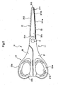
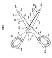
- a pair of scissors H is formed by coupling a first scissor body 11 having a movable blade 31 that is a first blade and a second scissor body 12 having a static blade 32 that is a second blade pairing up with the movable blade 31 so that they can turn about a pivot 4.
- the first scissor body 11 is made up of a first handle portion 21 having a first finger ring 21b through which a user puts his/her thumb and the movable blade 31 with a base end inserted into and mounted to a front end of the first handle portion 21.
- the first handle portion 21 includes a core portion made of rigid material such as thermoplastic resin and a soft portion made of elastic synthetic resin.
- the soft portion is formed at a first finger pad portion 21a that is a contact face with the thumb, i.e., at an inner peripheral portion of the first finger ring 21b.
- the thermoplastic resin include polyethylene, polystyrene, polypropylene, acrylate resin, and the like.
- examples of the elastic synthetic resin include rubber material or the like. In the example, these core portion and soft portion are formed by two-color molding. Then, as described above, the base end of the movable blade 31 is inserted into and mounted to the front end of the first handle portion 21.
- the movable blade 31 is to be put under paper or the like to cut the paper or the like with the pair of scissors H.
- the movable blade 31 is made up of a metal sheet made of stainless steel and is in a plate shape formed by integrally pressing the whole body. Thickness of the metal sheet can be set arbitrarily and is set to 1.5 mm in the example. In the example, as shown in FIGS.
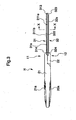
- the movable blade 31 includes an edge line portion 311 having a flat blade back face 311a for sliding against the static blade 32 and a recessed portion 31s formed by press forming at a portion adjacent to the edge line portion 311 with a difference in level from the edge line portion 311 and having a bottom face 31s1 that is away from a blade back face of the static blade 32 in a thickness direction and is substantially parallel to the blade back face 311a of the edge line portion 311, i.e., substantially flat.
- the static blade 32 forming the second scissor body 12 is mounted on the movable blade 31 by the pivot 4. A specific structure of the movable blade 31 will be described later.
- the second scissor body 12 is made up of a second handle portion 22 having a second finger ring 22b through which the user puts any of his/her index finger, middle finger, and ring finger and the static blade 32 that is the second blade with a base end inserted into and mounted to a front end of the second handle portion 22.
- the second handle portion 22 includes a core portion made of rigid material such as thermoplastic resin and a soft portion made of elastic synthetic resin.
- the soft portion is formed at a second finger pad portion 22a that is a contact face with the index finger, the middle finger, or the ring finger, i.e., at an inner peripheral portion of the second finger ring 22b.
- these core portion and soft portion are formed by two-color molding. Then, as described above, the base end of the static blade 32 is inserted into and mounted to the front end of the second handle portion 22.
- the static blade 32 pairs up with the movable blade 31 and is to be positioned above the paper or the like to cut the paper or the like with the pair of scissors H.
- the static blade 32 is made up of a metal sheet made of stainless steel and is in a plate shape formed by integrally pressing the whole body. In the embodiment, as shown in FIGS.
- the static blade 32 similarly includes an edge line portion 321 having a flat blade back face 321a for sliding against the movable blade 31 and a recessed portion 32s formed by press forming at a portion adjacent to the edge line portion 321 with a difference in level from the edge line portion 321 and having a bottom face 32s1 that is away from the blade back face of the movable blade 31 in a thickness direction and is substantially parallel to the blade back face 321a of the edge line portion 321, i.e., substantially flat.
- the movable blade 31 includes the edge line portion 311 having the flat blade back face 311a for sliding against the static blade 32 and the recessed portion 31s formed by press forming at the portion adjacent to the edge line portion 311 with the difference in level from the edge line portion 311 and having the bottom face 31s1 that is away from the blade back face of the static blade 32 in the thickness direction and is substantially parallel to the blade back face 311a of the edge line portion 311, i.e., substantially flat.
- an edge line 311e is formed between the blade back face 311a and a blade surface 311b.
- a blade angle ⁇ between the blade back face 311a and the blade surface 311b is set to an angle of 70 degees in the embodiment.
- Width d1 of the edge line portion 311 is set to be in a range of 0.8 to 1.2 mm and preferably 1.0 mm in the embodiment.
- the movable blade 31 further includes a blade back portion 312 formed at an opposite side end edge from the edge line portion 311 and having a back face in the same plane as the blade back face 311a, a blade tip portion 313 positioned at a tip end portion and having a back face continuous with and in the same plane as the blade back face 311a, and a blade base portion 314 positioned in a vicinity of a base end portion, i.e., the pivot 4 and having a back face continuous with and in the same plane as the blade back face 311a.
- back faces of the blade back portion 312, the blade tip portion 313, and the blade base portion 314 are continuous with and form the same plane with the blade back face 311a that is the back face of the edge line portion 311.
- a continuous step forming face 31s2 is formed between the bottom face 31s1 of the recessed portion 31s, and the blade back face 311a, the back face of the blade back portion 312, the back face of the blade tip portion 313, and the back face of the blade base portion 314. Therefore, the recessed portion 31s is open only in a direction toward the static blade 32. A portion, which corresponds to the recessed portion 31s, of an outer face 31c as a face of the movable blade 31 facing away from the static blade 32 is displaced further away from the static blade 32 than the other portion.
- the portion of the substantially flat metal sheet other than the end edge portion is recessed by press forming to form the recessed portion 31s.
- the bottom face 31s1 of the recessed portion 31s and the blade back face 311a are at least 0.25 mm away from each other in the thickness direction.
- the static blade 32 has substantially the same structure as the movable blade 31 in the example. Specifically, as shown in FIGS. 4 and 5 and as described above, the static blade 32 includes the edge line portion 321 having the flat blade back face 321a for sliding against the movable blade 31 and the recessed portion 32s formed by press forming at the portion adjacent to the edge line portion 321 with the difference in level from the edge line portion 321 and having the bottom face 32s1 that is away from the blade back face of the movable blade 31 in the thickness direction and is substantially parallel to the blade back face 321a of the edge line portion 321, i.e., substantially flat.
- an edge line 321e is formed between the blade back face 311a and a blade surface 311b.
- a blade angle ⁇ between the blade back face 321a and the blade surface 321b is set to an angle of 70 degrees as well in the example.
- Width of the edge line portion 321 is the same as the width d1 of the edge line portion 311 of the movable blade. In other words, the width is set to be in the range of 0.8 to 1.2 mm and preferably 1.0 mm in the example.
- the static blade 32 further includes a blade back portion 322 formed at an opposite side end edge from the edge line portion 321 and having a back face in the same plane as the blade back face 321a, a blade tip portion 323 positioned at a tip end portion and having a back face continuous with and in the same plane as the blade back face 321a, and a blade base portion 324 positioned in a vicinity of a base end portion, i.e., the pivot 4 and having a back face continuous with and in the same plane as the blade back face 321a.
- back faces of the blade back portion 322, the blade tip portion 323, and the blade base portion 324 are continuous with and forms the same plane with the blade back face 321a that is the back face of the edge line portion 321.
- a continuous step forming face 32s2 is formed between the bottom face 32s1 of the recessed portion 32s, and the blade back face 321a, the back face of the blade back portion 322, the back face of the blade tip portion 323, and the back face of the blade base portion 324. Therefore, the recessed portion 32s is open only in a direction toward the movable blade 31. A portion, which corresponds to the recessed portion 32s, of an outer face 32c as a face of the static blade 32 facing away from the movable blade 31 is displaced further away from the movable blade 31 than the other portion. In other words, in the example, the portion of the substantially flat metal sheet other than the end edge portion is recessed by press forming to form the recessed portion 32s. In the example, the bottom face 32s1 of the recessed portion 32s and the blade back face 321a are at least 0.25 mm away from each other in the thickness direction.
- the step forming faces 32s1 and 32s2 are not orthogonal to the blade back faces 311a and 321a and the bottom faces 31s1 and 32s1 of recessed portions 31s and 32s but inclined with respect to normals to the bottom faces 31s1 and 32s1.
- the edge lines 311e and 321e of the movable blade 31 and the static blade 32 first come in contact with the object of cutting. Then, if the first and second handle portions 21 and 22 are operated to approach each other, the edge lines 311e and 321e press the object of cutting from opposite sides of the object of cutting to thereby cut the object. At this time, the blade back faces 311a and 321a of the edge line portions 311 and 321 slide against each other. At this time, as described above, though the adhesive temporarily adheres to the blade back faces 311a and 321a, the adhesive is pushed out and moves into the recessed portions 31s and 32s as the blade back faces 311a and 321a slide against each other.
- the following effects can be obtained in addition to the above-described effect of moving the adhesive or the like applied on the tape or the sheet as the object of cutting into the recessed portions 31s and 32s from the blade back faces 311a and 321a to thereby suppress impairing of the operability of the pair of scissors H due to the adhesive or the like that has adhered to the blade back faces 311a and 321a.
- the blade back faces 311a and 321a of the edge line portions 311 and 321 and the bottom faces 31s1 and 31s2 of the recessed portions 31s and 32s are substantially parallel to each other and substantially flat and therefore it is possible to form the movable blade 31 and the static blade 32 almost without considering change in shapes due to warping again due to resilience after the flat metal sheets are formed into the blades. Therefore, it is possible to easily form the movable blade 31 and the static blade 32 by press working without requiring high working accuracy by employing any metal sheet.
- the whole movable blade 31 and the whole static blade 32 are in substantially flat plate shapes and therefore thickness of the edge line portions 311 and 321 can be secured and the blade angles ⁇ can be reduced in order to increase sharpness as compared with the movable blade 31 and the static blade 32 with curved sections.
- the width d1 of the edge line portions 311 and 321 is set to 0.8 mm to 1. 2 mm, it is possible to suppress adhesion of the adhesive to the edge line portions 311 and 321 while securing strength of the movable blade 31 and the static blade 32 of the pair of scissors H, i.e. , suppressing occurrence of nicking of the edges that may happen when the width d1 of the edge line portions 311 and 321 is reduced.
- bottom faces 31s1 and 32s1 of the recessed portions 31s and 32s and the blade back faces 311a and 321a are 0.25 mm or more away from each other in the thickness direction, it is possible to further effectively suppress adhesion of the adhesive to the edge line portions 311 and 321.
- the movable blade 31 and the static blade 32 include the edge line portions 311 and 321 and the blade back portions 312 and 322 formed at the opposite side end edges from the edge line portions 311 and 321 and having the back faces in the same planes as the blade back faces 311a and 321a of the edge line portions and the recessed portions 31s and 32s have the step forming faces 31s2 and 32s2 respectively formed between the bottom faces 31s1 and 32s1 and the blade back faces 311a and 321a of the edge line portions 311 and 321 and between the bottom faces 31s1 and 32s1 and the blade back faces 311a and 321a that are the back faces of the blade back portions, which positively influences the strength of the movable blade 31 and the static blade 32.
- the movable blade 31 and the static blade 32 further include the blade tip portions 313 and 323 positioned at the tip end portions and having the back faces positioned in the same planes as the blade back faces 311a and 321a of the edge line portions and the blade base portions 314 and 324 positioned at the base end portions and having the back faces positioned in the same planes as the blade back faces 311a and 321a of the edge line portions and the step forming faces 31s2 and 32s2 are further formed between the bottom faces 31s1 and 32s1 and the blade back faces 311a and 321a that are the back faces of the blade tip portions and the blade base portions, which further positively influences the strength of the movable blade 31 and the static blade 32.
- the present invention is reflected by an embodiment as shown in Fig. 6 .
- the recessed portions of the blades are open only in the directions toward the other blades in the example described above, the recessed portions may be open on at least one of the blade tip sides and the blade back sides as well.
- the recessed portions 31s and 32s are open both on the sides of blade tips 31a and 32a and on the sides of blade backs 31b and 32b and portions similar or corresponding to those in the example shown in FIGS. 1 to 5 are provided with similar reference numerals to omit their description.
- the width of the edge line portions is set to 0.8 mm to 1.2 mm from the viewpoint of performance in the embodiment described above, the width of the edge line portions may be set to 0.3 mm to 1. 2 mm from the view point of practicality. In other words, the width of the edge line portions may be smaller than 0.8 mm if other measures such as employment of high-strength metallic material are taken to increase strength of the edge line portions. If the movable blade and the static blade are made up of metal sheets made of stainless steel and are in plate shapes formed by integrally pressing the whole bodies, the width of about 0.3 mm at the minimum is acceptable as a matter of practicality.
- the distances between the bottom face of the recessed portions and the blade back faces in the thickness direction may be shorter than 0.25 mm if the pair of scissors is used exclusively for cutting of tapes and sheets on which adhesive less likely to adhere to the blades is applied.
- the present invention can be changed in various ways without departing from the gist of the present invention.
Landscapes
- Life Sciences & Earth Sciences (AREA)
- Forests & Forestry (AREA)
- Engineering & Computer Science (AREA)
- Mechanical Engineering (AREA)
- Scissors And Nippers (AREA)
Claims (4)
- Schere mit einem Paar an jeweils durch einen Pressvorgang ausgebildeten plattenförmigen Klingen (31, 32), die in Büros und im Haushalt verwendet wird, um ein auf seiner Oberfläche mit einem Haftmittel versehenes Objekt zu schneiden, wobei jede der Klingen (31, 32), die miteinander ein Paar bilden, einen Randlinienabschnitt (311, 321) hat, um an der anderen Klinge zu gleiten, und einen vertieften Abschnitt (31s, 32s) hat, der an einem Abschnitt, der benachbart zu dem Randlinienabschnitt (311, 321) mit einer Höhendifferenz von dem Randlinienabschnitt (311, 321) ausgebildet ist, der von einer Klingenrückseite (311a, 321a) der anderen Klinge in der Dickenrichtung entfernt ist, und der eine Bodenfläche (31s1, 32s1) hat, die im Wesentlichen parallel und im Wesentlichen flach zu der Klingenrückseite (311a, 321a) des Randlinienabschnittes (311, 321) ist, und wobei ein Abschnitt, der dem vertieften Abschnitt (31s, 32s) in einer Außenfläche (31c, 32c) jeder der Klingen (31, 32), die ein Paar bilden, entspricht, eine Fläche hat, die im Wesentlichen parallel und im Wesentlichen flach zu einer Bodenfläche (31s1, 32s1) von jedem vertieften Abschnitt (31s, 32s) ist,
dadurch gekennzeichnet, dass
eine Breite (d1) der Randlinienabschnitte (311, 321) auf 0,8 mm bis 1,2 mm festgelegt ist, und der vertiefte Abschnitt (31s, 32s) an den Klingenrückseiten (31b, 32b), die entgegengesetzt zu dem Randlinienabschnitt (311, 321) sind, offen ist. - Schere gemäß Anspruch 1, wobei der vertiefte Abschnitt (31s, 32s) auch zu der Klingenendstückseite (31a, 32a) offen ist.
- Schere gemäß Anspruch 1 oder 2, wobei jeder vertiefte Abschnitt (31s, 32s) jeder Klinge (31, 32) eine einen Absatz ausbildende Fläche (31s2, 32s2) hat, die zwischen der Bodenfläche (31s1, 32s1) und der Klingenrückseite (311a, 321a) des Randlinienabschnittes (311, 321) ausgebildet ist, wobei die den Absatz ausbildende Fläche (31s2, 32s2) nicht senkrecht zu der Klingenrückseite (311a, 321a) und der Bodenfläche (31s1, 32s1) des vertieften Abschnittes (31s, 32s) ist, sondern geneigt zu einer Normalen der Bodenfläche (31s1, 32s1) ist.
- Schere gemäß Anspruch 1, 2 oder 3, wobei jede Klinge (31, 32) einen Klingenbasisabschnitt (314, 324), der an einem Basisendabschnitt positioniert ist, und eine Rückseite hat, die in der gleichen Ebene wie die Klingenrückseite (311a, 321a) des Randlinienabschnittes (311, 321) positioniert ist, und jeder vertiefte Abschnitt (31s, 32s) jeder Klinge (31, 32) eine einen Absatz ausbildende Fläche (31s2, 32s2) hat, die zwischen der Bodenfläche (31s1, 32s1) des vertieften Abschnittes (31s, 32s) und einer Rückseitenfläche (311a, 321a) des Klingenbasisabschnittes (314, 324) ausgebildet ist.
Applications Claiming Priority (2)
| Application Number | Priority Date | Filing Date | Title |
|---|---|---|---|
| JP2009100654 | 2009-04-17 | ||
| JP2010062395A JP2010264229A (ja) | 2009-04-17 | 2010-03-18 | 鋏 |
Publications (2)
| Publication Number | Publication Date |
|---|---|
| EP2241418A1 EP2241418A1 (de) | 2010-10-20 |
| EP2241418B1 true EP2241418B1 (de) | 2012-11-21 |
Family
ID=42288979
Family Applications (1)
| Application Number | Title | Priority Date | Filing Date |
|---|---|---|---|
| EP10158684A Active EP2241418B1 (de) | 2009-04-17 | 2010-03-31 | Schere |
Country Status (5)
| Country | Link |
|---|---|
| US (1) | US8677631B2 (de) |
| EP (1) | EP2241418B1 (de) |
| JP (1) | JP2010264229A (de) |
| CN (1) | CN101863042B (de) |
| ES (1) | ES2397532T3 (de) |
Families Citing this family (14)
| Publication number | Priority date | Publication date | Assignee | Title |
|---|---|---|---|---|
| US8424211B2 (en) * | 2010-08-31 | 2013-04-23 | Helen Of Troy Limited | Separable scissors with elastic stoppers |
| USD678021S1 (en) * | 2011-10-06 | 2013-03-19 | Kokuyo Co., Ltd. | Scissors |
| CA2888500A1 (en) * | 2012-12-21 | 2014-06-26 | Owen PAPWORTH | Improved scissors |
| JP6070276B2 (ja) * | 2013-03-01 | 2017-02-01 | コクヨ株式会社 | 鋏、柄、及び用具 |
| JP6244097B2 (ja) * | 2013-04-01 | 2017-12-06 | プラス株式会社 | 事務用鋏 |
| TWD162015S (zh) * | 2013-04-04 | 2014-08-01 | 普樂士股份有限公司 | 剪刀之刃部 |
| US11161261B2 (en) | 2014-03-12 | 2021-11-02 | Hangzhou Great Star Tools Co., Ltd. | Scissors |
| CN104908068B (zh) * | 2014-03-13 | 2020-11-06 | 杭州巨星工具有限公司 | 剪刀 |
| US9393705B2 (en) * | 2014-04-23 | 2016-07-19 | Havel's Inc. | Scissors for accessing an acute angle between sewn layers of material |
| JP2015211743A (ja) * | 2014-05-02 | 2015-11-26 | プラス株式会社 | 鋏 |
| JP2015211742A (ja) * | 2014-05-02 | 2015-11-26 | プラス株式会社 | 鋏 |
| USD1122704S1 (en) * | 2024-03-01 | 2026-04-21 | Fiskars Finland Oy Ab | Garden detail snips |
| USD1122058S1 (en) * | 2024-03-01 | 2026-04-14 | Fiskars Finland Oy Ab | Garden detail snips |
| USD1122703S1 (en) * | 2024-03-01 | 2026-04-21 | Fiskars Finland Oy Ab | Garden detail snips |
Family Cites Families (16)
| Publication number | Priority date | Publication date | Assignee | Title |
|---|---|---|---|---|
| US643539A (en) * | 1899-06-10 | 1900-02-13 | George B Rowe | Shears. |
| DE801895C (de) | 1948-10-02 | 1951-01-25 | Rudolf Lang | Schere |
| GB774767A (en) | 1955-10-21 | 1957-05-15 | Fred Maeder | Improvements in scissors |
| US3316638A (en) * | 1965-09-02 | 1967-05-02 | Mihalyi Joseph | Hedge shears |
| US3987542A (en) * | 1975-08-22 | 1976-10-26 | Visco Luigi P | Scissors |
| US4150484A (en) * | 1977-11-02 | 1979-04-24 | The Stanley Works | Shears with improved cutting action and method of making same |
| GB2049528A (en) * | 1979-05-02 | 1980-12-31 | British Syphon Ind Ltd | An improvement in or relating to scissors |
| JPS5845642A (ja) * | 1981-07-31 | 1983-03-16 | Clarion Co Ltd | 磁気テ−プ装置 |
| JPS61170472A (ja) * | 1985-01-25 | 1986-08-01 | 宇部興産株式会社 | 高圧蒸気滅菌人工臓器 |
| DE4140425C1 (en) | 1991-12-07 | 1992-08-27 | Pietro Cecina Mare Livorno It Poggetti | Hair cutting scissors of two elongated halves - has each blade with two cutting edges in cutting plane with mutual orthogonal spacing |
| US5303475A (en) * | 1992-08-21 | 1994-04-19 | Flexcutter, Inc. | Flexible ducting cutting tool |
| JP2003025274A (ja) * | 2001-07-18 | 2003-01-29 | Fuji Photo Film Co Ltd | 切断装置 |
| JP2004148442A (ja) * | 2002-10-30 | 2004-05-27 | Sato Corp | ラベルプリンタのカッターユニット |
| JP2004248707A (ja) * | 2003-02-18 | 2004-09-09 | Kanematsu Kogyo Kk | シート用刃物 |
| US7966735B1 (en) * | 2008-04-04 | 2011-06-28 | Hasbro, Inc. | Scissors assembly with rotatable blades |
| US20110203117A1 (en) * | 2010-02-25 | 2011-08-25 | Ho Cheng Garden Tools Co., Ltd. | Garden shear cutting head with a lubricated pivot |
-
2010
- 2010-03-18 JP JP2010062395A patent/JP2010264229A/ja active Pending
- 2010-03-31 ES ES10158684T patent/ES2397532T3/es active Active
- 2010-03-31 EP EP10158684A patent/EP2241418B1/de active Active
- 2010-03-31 US US12/662,131 patent/US8677631B2/en active Active
- 2010-04-15 CN CN201010161969.9A patent/CN101863042B/zh active Active
Also Published As
| Publication number | Publication date |
|---|---|
| US20100263216A1 (en) | 2010-10-21 |
| EP2241418A1 (de) | 2010-10-20 |
| US8677631B2 (en) | 2014-03-25 |
| JP2010264229A (ja) | 2010-11-25 |
| CN101863042A (zh) | 2010-10-20 |
| HK1146920A1 (en) | 2011-07-22 |
| CN101863042B (zh) | 2015-01-28 |
| ES2397532T3 (es) | 2013-03-07 |
Similar Documents
| Publication | Publication Date | Title |
|---|---|---|
| EP2241418B1 (de) | Schere | |
| US11577412B2 (en) | Utility knife | |
| US20140290071A1 (en) | Scissors | |
| CA2605653A1 (en) | Media cutting device | |
| EP1478521B1 (de) | Deformierbares zeichenlineal mit rutschverhinderungsmitteln | |
| CN104411468B (zh) | 剪刀 | |
| KR101845380B1 (ko) | 손톱깎이 | |
| EP1247658A2 (de) | Ordner | |
| US20180050556A1 (en) | File | |
| US7921574B2 (en) | Ruler with safety shield | |
| HK1146920B (en) | Scissor | |
| JP6623931B2 (ja) | 切断用定規 | |
| US20220169065A1 (en) | Layout Tool With Grips | |
| JP6954515B2 (ja) | 目地材集合体及びその製造方法 | |
| US20250224817A1 (en) | Mouse device, mouse foot, and batch manufacturing method of mouse feet replacement assembly | |
| JP3177664U (ja) | 切断具 | |
| JP3111685U (ja) | 滑り止め付き定規 | |
| JP3346681B2 (ja) | 切断具 | |
| JP2026038398A (ja) | 鋏 | |
| JP2026038400A (ja) | 鋏 | |
| JP2026038399A (ja) | 鋏 | |
| JPH10128874A (ja) | 抜き型の罫押し溝用型材 | |
| CN201587005U (zh) | 折合式切割垫 | |
| JP2021014326A (ja) | テープカッター | |
| JPH0430885A (ja) | カッター |
Legal Events
| Date | Code | Title | Description |
|---|---|---|---|
| PUAI | Public reference made under article 153(3) epc to a published international application that has entered the european phase |
Free format text: ORIGINAL CODE: 0009012 |
|
| AK | Designated contracting states |
Kind code of ref document: A1 Designated state(s): AT BE BG CH CY CZ DE DK EE ES FI FR GB GR HR HU IE IS IT LI LT LU LV MC MK MT NL NO PL PT RO SE SI SK SM TR |
|
| AX | Request for extension of the european patent |
Extension state: AL BA ME RS |
|
| 17P | Request for examination filed |
Effective date: 20110408 |
|
| 17Q | First examination report despatched |
Effective date: 20110926 |
|
| GRAP | Despatch of communication of intention to grant a patent |
Free format text: ORIGINAL CODE: EPIDOSNIGR1 |
|
| RAP1 | Party data changed (applicant data changed or rights of an application transferred) |
Owner name: KOKUYO CO., LTD. |
|
| GRAS | Grant fee paid |
Free format text: ORIGINAL CODE: EPIDOSNIGR3 |
|
| GRAA | (expected) grant |
Free format text: ORIGINAL CODE: 0009210 |
|
| AK | Designated contracting states |
Kind code of ref document: B1 Designated state(s): AT BE BG CH CY CZ DE DK EE ES FI FR GB GR HR HU IE IS IT LI LT LU LV MC MK MT NL NO PL PT RO SE SI SK SM TR |
|
| REG | Reference to a national code |
Ref country code: GB Ref legal event code: FG4D |
|
| REG | Reference to a national code |
Ref country code: CH Ref legal event code: EP |
|
| REG | Reference to a national code |
Ref country code: AT Ref legal event code: REF Ref document number: 584803 Country of ref document: AT Kind code of ref document: T Effective date: 20121215 |
|
| REG | Reference to a national code |
Ref country code: IE Ref legal event code: FG4D |
|
| REG | Reference to a national code |
Ref country code: DE Ref legal event code: R096 Ref document number: 602010003675 Country of ref document: DE Effective date: 20130117 |
|
| REG | Reference to a national code |
Ref country code: ES Ref legal event code: FG2A Ref document number: 2397532 Country of ref document: ES Kind code of ref document: T3 Effective date: 20130307 |
|
| REG | Reference to a national code |
Ref country code: NL Ref legal event code: VDEP Effective date: 20121121 |
|
| REG | Reference to a national code |
Ref country code: AT Ref legal event code: MK05 Ref document number: 584803 Country of ref document: AT Kind code of ref document: T Effective date: 20121121 |
|
| REG | Reference to a national code |
Ref country code: LT Ref legal event code: MG4D |
|
| PG25 | Lapsed in a contracting state [announced via postgrant information from national office to epo] |
Ref country code: LT Free format text: LAPSE BECAUSE OF FAILURE TO SUBMIT A TRANSLATION OF THE DESCRIPTION OR TO PAY THE FEE WITHIN THE PRESCRIBED TIME-LIMIT Effective date: 20121121 Ref country code: HR Free format text: LAPSE BECAUSE OF FAILURE TO SUBMIT A TRANSLATION OF THE DESCRIPTION OR TO PAY THE FEE WITHIN THE PRESCRIBED TIME-LIMIT Effective date: 20121121 Ref country code: FI Free format text: LAPSE BECAUSE OF FAILURE TO SUBMIT A TRANSLATION OF THE DESCRIPTION OR TO PAY THE FEE WITHIN THE PRESCRIBED TIME-LIMIT Effective date: 20121121 Ref country code: SE Free format text: LAPSE BECAUSE OF FAILURE TO SUBMIT A TRANSLATION OF THE DESCRIPTION OR TO PAY THE FEE WITHIN THE PRESCRIBED TIME-LIMIT Effective date: 20121121 Ref country code: NO Free format text: LAPSE BECAUSE OF FAILURE TO SUBMIT A TRANSLATION OF THE DESCRIPTION OR TO PAY THE FEE WITHIN THE PRESCRIBED TIME-LIMIT Effective date: 20130221 |
|
| PG25 | Lapsed in a contracting state [announced via postgrant information from national office to epo] |
Ref country code: SI Free format text: LAPSE BECAUSE OF FAILURE TO SUBMIT A TRANSLATION OF THE DESCRIPTION OR TO PAY THE FEE WITHIN THE PRESCRIBED TIME-LIMIT Effective date: 20121121 Ref country code: GR Free format text: LAPSE BECAUSE OF FAILURE TO SUBMIT A TRANSLATION OF THE DESCRIPTION OR TO PAY THE FEE WITHIN THE PRESCRIBED TIME-LIMIT Effective date: 20130222 Ref country code: PL Free format text: LAPSE BECAUSE OF FAILURE TO SUBMIT A TRANSLATION OF THE DESCRIPTION OR TO PAY THE FEE WITHIN THE PRESCRIBED TIME-LIMIT Effective date: 20121121 Ref country code: LV Free format text: LAPSE BECAUSE OF FAILURE TO SUBMIT A TRANSLATION OF THE DESCRIPTION OR TO PAY THE FEE WITHIN THE PRESCRIBED TIME-LIMIT Effective date: 20121121 Ref country code: PT Free format text: LAPSE BECAUSE OF FAILURE TO SUBMIT A TRANSLATION OF THE DESCRIPTION OR TO PAY THE FEE WITHIN THE PRESCRIBED TIME-LIMIT Effective date: 20130321 Ref country code: BE Free format text: LAPSE BECAUSE OF FAILURE TO SUBMIT A TRANSLATION OF THE DESCRIPTION OR TO PAY THE FEE WITHIN THE PRESCRIBED TIME-LIMIT Effective date: 20121121 |
|
| PG25 | Lapsed in a contracting state [announced via postgrant information from national office to epo] |
Ref country code: AT Free format text: LAPSE BECAUSE OF FAILURE TO SUBMIT A TRANSLATION OF THE DESCRIPTION OR TO PAY THE FEE WITHIN THE PRESCRIBED TIME-LIMIT Effective date: 20121121 |
|
| PG25 | Lapsed in a contracting state [announced via postgrant information from national office to epo] |
Ref country code: CZ Free format text: LAPSE BECAUSE OF FAILURE TO SUBMIT A TRANSLATION OF THE DESCRIPTION OR TO PAY THE FEE WITHIN THE PRESCRIBED TIME-LIMIT Effective date: 20121121 Ref country code: BG Free format text: LAPSE BECAUSE OF FAILURE TO SUBMIT A TRANSLATION OF THE DESCRIPTION OR TO PAY THE FEE WITHIN THE PRESCRIBED TIME-LIMIT Effective date: 20130221 Ref country code: SK Free format text: LAPSE BECAUSE OF FAILURE TO SUBMIT A TRANSLATION OF THE DESCRIPTION OR TO PAY THE FEE WITHIN THE PRESCRIBED TIME-LIMIT Effective date: 20121121 Ref country code: DK Free format text: LAPSE BECAUSE OF FAILURE TO SUBMIT A TRANSLATION OF THE DESCRIPTION OR TO PAY THE FEE WITHIN THE PRESCRIBED TIME-LIMIT Effective date: 20121121 Ref country code: EE Free format text: LAPSE BECAUSE OF FAILURE TO SUBMIT A TRANSLATION OF THE DESCRIPTION OR TO PAY THE FEE WITHIN THE PRESCRIBED TIME-LIMIT Effective date: 20121121 |
|
| PG25 | Lapsed in a contracting state [announced via postgrant information from national office to epo] |
Ref country code: NL Free format text: LAPSE BECAUSE OF FAILURE TO SUBMIT A TRANSLATION OF THE DESCRIPTION OR TO PAY THE FEE WITHIN THE PRESCRIBED TIME-LIMIT Effective date: 20121121 Ref country code: RO Free format text: LAPSE BECAUSE OF FAILURE TO SUBMIT A TRANSLATION OF THE DESCRIPTION OR TO PAY THE FEE WITHIN THE PRESCRIBED TIME-LIMIT Effective date: 20121121 |
|
| PLBE | No opposition filed within time limit |
Free format text: ORIGINAL CODE: 0009261 |
|
| STAA | Information on the status of an ep patent application or granted ep patent |
Free format text: STATUS: NO OPPOSITION FILED WITHIN TIME LIMIT |
|
| 26N | No opposition filed |
Effective date: 20130822 |
|
| PG25 | Lapsed in a contracting state [announced via postgrant information from national office to epo] |
Ref country code: MC Free format text: LAPSE BECAUSE OF NON-PAYMENT OF DUE FEES Effective date: 20130331 |
|
| REG | Reference to a national code |
Ref country code: DE Ref legal event code: R097 Ref document number: 602010003675 Country of ref document: DE Effective date: 20130822 |
|
| REG | Reference to a national code |
Ref country code: IE Ref legal event code: MM4A |
|
| PG25 | Lapsed in a contracting state [announced via postgrant information from national office to epo] |
Ref country code: IE Free format text: LAPSE BECAUSE OF NON-PAYMENT OF DUE FEES Effective date: 20130331 |
|
| PG25 | Lapsed in a contracting state [announced via postgrant information from national office to epo] |
Ref country code: MT Free format text: LAPSE BECAUSE OF FAILURE TO SUBMIT A TRANSLATION OF THE DESCRIPTION OR TO PAY THE FEE WITHIN THE PRESCRIBED TIME-LIMIT Effective date: 20121121 |
|
| REG | Reference to a national code |
Ref country code: CH Ref legal event code: PL |
|
| PG25 | Lapsed in a contracting state [announced via postgrant information from national office to epo] |
Ref country code: LI Free format text: LAPSE BECAUSE OF NON-PAYMENT OF DUE FEES Effective date: 20140331 Ref country code: CH Free format text: LAPSE BECAUSE OF NON-PAYMENT OF DUE FEES Effective date: 20140331 |
|
| PGFP | Annual fee paid to national office [announced via postgrant information from national office to epo] |
Ref country code: ES Payment date: 20150212 Year of fee payment: 6 |
|
| PG25 | Lapsed in a contracting state [announced via postgrant information from national office to epo] |
Ref country code: SM Free format text: LAPSE BECAUSE OF FAILURE TO SUBMIT A TRANSLATION OF THE DESCRIPTION OR TO PAY THE FEE WITHIN THE PRESCRIBED TIME-LIMIT Effective date: 20121121 |
|
| PG25 | Lapsed in a contracting state [announced via postgrant information from national office to epo] |
Ref country code: TR Free format text: LAPSE BECAUSE OF FAILURE TO SUBMIT A TRANSLATION OF THE DESCRIPTION OR TO PAY THE FEE WITHIN THE PRESCRIBED TIME-LIMIT Effective date: 20121121 Ref country code: CY Free format text: LAPSE BECAUSE OF FAILURE TO SUBMIT A TRANSLATION OF THE DESCRIPTION OR TO PAY THE FEE WITHIN THE PRESCRIBED TIME-LIMIT Effective date: 20121121 |
|
| PG25 | Lapsed in a contracting state [announced via postgrant information from national office to epo] |
Ref country code: LU Free format text: LAPSE BECAUSE OF NON-PAYMENT OF DUE FEES Effective date: 20130331 Ref country code: HU Free format text: LAPSE BECAUSE OF FAILURE TO SUBMIT A TRANSLATION OF THE DESCRIPTION OR TO PAY THE FEE WITHIN THE PRESCRIBED TIME-LIMIT; INVALID AB INITIO Effective date: 20100331 Ref country code: MK Free format text: LAPSE BECAUSE OF FAILURE TO SUBMIT A TRANSLATION OF THE DESCRIPTION OR TO PAY THE FEE WITHIN THE PRESCRIBED TIME-LIMIT Effective date: 20121121 |
|
| REG | Reference to a national code |
Ref country code: FR Ref legal event code: PLFP Year of fee payment: 7 |
|
| PG25 | Lapsed in a contracting state [announced via postgrant information from national office to epo] |
Ref country code: IS Free format text: LAPSE BECAUSE OF FAILURE TO SUBMIT A TRANSLATION OF THE DESCRIPTION OR TO PAY THE FEE WITHIN THE PRESCRIBED TIME-LIMIT Effective date: 20121121 |
|
| REG | Reference to a national code |
Ref country code: FR Ref legal event code: PLFP Year of fee payment: 8 |
|
| REG | Reference to a national code |
Ref country code: ES Ref legal event code: FD2A Effective date: 20170427 |
|
| PG25 | Lapsed in a contracting state [announced via postgrant information from national office to epo] |
Ref country code: ES Free format text: LAPSE BECAUSE OF NON-PAYMENT OF DUE FEES Effective date: 20160401 |
|
| REG | Reference to a national code |
Ref country code: FR Ref legal event code: PLFP Year of fee payment: 9 |
|
| P01 | Opt-out of the competence of the unified patent court (upc) registered |
Effective date: 20230421 |
|
| PGFP | Annual fee paid to national office [announced via postgrant information from national office to epo] |
Ref country code: GB Payment date: 20260209 Year of fee payment: 17 |
|
| PGFP | Annual fee paid to national office [announced via postgrant information from national office to epo] |
Ref country code: DE Payment date: 20260204 Year of fee payment: 17 |
|
| PGFP | Annual fee paid to national office [announced via postgrant information from national office to epo] |
Ref country code: IT Payment date: 20260220 Year of fee payment: 17 |
|
| PGFP | Annual fee paid to national office [announced via postgrant information from national office to epo] |
Ref country code: FR Payment date: 20260209 Year of fee payment: 17 |