EP2241403A1 - Outil de manipulation et outil pour fixer et/ou écarter avec au moins un outil de manipulation - Google Patents
Outil de manipulation et outil pour fixer et/ou écarter avec au moins un outil de manipulation Download PDFInfo
- Publication number
- EP2241403A1 EP2241403A1 EP10002411A EP10002411A EP2241403A1 EP 2241403 A1 EP2241403 A1 EP 2241403A1 EP 10002411 A EP10002411 A EP 10002411A EP 10002411 A EP10002411 A EP 10002411A EP 2241403 A1 EP2241403 A1 EP 2241403A1
- Authority
- EP
- European Patent Office
- Prior art keywords
- tool
- cheek
- manipulator
- cheeks
- distal end
- Prior art date
- Legal status (The legal status is an assumption and is not a legal conclusion. Google has not performed a legal analysis and makes no representation as to the accuracy of the status listed.)
- Granted
Links
Images


Classifications
-
- B—PERFORMING OPERATIONS; TRANSPORTING
- B25—HAND TOOLS; PORTABLE POWER-DRIVEN TOOLS; MANIPULATORS
- B25B—TOOLS OR BENCH DEVICES NOT OTHERWISE PROVIDED FOR, FOR FASTENING, CONNECTING, DISENGAGING OR HOLDING
- B25B9/00—Hand-held gripping tools other than those covered by group B25B7/00
-
- A—HUMAN NECESSITIES
- A61—MEDICAL OR VETERINARY SCIENCE; HYGIENE
- A61B—DIAGNOSIS; SURGERY; IDENTIFICATION
- A61B17/00—Surgical instruments, devices or methods, e.g. tourniquets
- A61B17/02—Surgical instruments, devices or methods, e.g. tourniquets for holding wounds open; Tractors
- A61B17/0206—Surgical instruments, devices or methods, e.g. tourniquets for holding wounds open; Tractors with antagonistic arms as supports for retractor elements
-
- A—HUMAN NECESSITIES
- A61—MEDICAL OR VETERINARY SCIENCE; HYGIENE
- A61B—DIAGNOSIS; SURGERY; IDENTIFICATION
- A61B17/00—Surgical instruments, devices or methods, e.g. tourniquets
- A61B17/28—Surgical forceps
- A61B17/29—Forceps for use in minimally invasive surgery
-
- A—HUMAN NECESSITIES
- A61—MEDICAL OR VETERINARY SCIENCE; HYGIENE
- A61B—DIAGNOSIS; SURGERY; IDENTIFICATION
- A61B17/00—Surgical instruments, devices or methods, e.g. tourniquets
- A61B17/30—Surgical pincettes without pivotal connections
-
- B—PERFORMING OPERATIONS; TRANSPORTING
- B25—HAND TOOLS; PORTABLE POWER-DRIVEN TOOLS; MANIPULATORS
- B25B—TOOLS OR BENCH DEVICES NOT OTHERWISE PROVIDED FOR, FOR FASTENING, CONNECTING, DISENGAGING OR HOLDING
- B25B7/00—Pliers; Other hand-held gripping tools with jaws on pivoted limbs; Details applicable generally to pivoted-limb hand tools
- B25B7/02—Jaws
-
- B—PERFORMING OPERATIONS; TRANSPORTING
- B25—HAND TOOLS; PORTABLE POWER-DRIVEN TOOLS; MANIPULATORS
- B25J—MANIPULATORS; CHAMBERS PROVIDED WITH MANIPULATION DEVICES
- B25J15/00—Gripping heads and other end effectors
- B25J15/08—Gripping heads and other end effectors having finger members
- B25J15/10—Gripping heads and other end effectors having finger members with three or more finger members
-
- A—HUMAN NECESSITIES
- A61—MEDICAL OR VETERINARY SCIENCE; HYGIENE
- A61B—DIAGNOSIS; SURGERY; IDENTIFICATION
- A61B10/00—Other methods or instruments for diagnosis, e.g. instruments for taking a cell sample, for biopsy, for vaccination diagnosis; Sex determination; Ovulation-period determination; Throat striking implements
- A61B10/02—Instruments for taking cell samples or for biopsy
- A61B10/06—Biopsy forceps, e.g. with cup-shaped jaws
-
- A—HUMAN NECESSITIES
- A61—MEDICAL OR VETERINARY SCIENCE; HYGIENE
- A61B—DIAGNOSIS; SURGERY; IDENTIFICATION
- A61B17/00—Surgical instruments, devices or methods, e.g. tourniquets
- A61B17/02—Surgical instruments, devices or methods, e.g. tourniquets for holding wounds open; Tractors
-
- A—HUMAN NECESSITIES
- A61—MEDICAL OR VETERINARY SCIENCE; HYGIENE
- A61B—DIAGNOSIS; SURGERY; IDENTIFICATION
- A61B17/00—Surgical instruments, devices or methods, e.g. tourniquets
- A61B17/22—Implements for squeezing-off ulcers or the like on the inside of inner organs of the body; Implements for scraping-out cavities of body organs, e.g. bones; Calculus removers; Calculus smashing apparatus; Apparatus for removing obstructions in blood vessels, not otherwise provided for
- A61B17/22031—Gripping instruments, e.g. forceps, for removing or smashing calculi
-
- A—HUMAN NECESSITIES
- A61—MEDICAL OR VETERINARY SCIENCE; HYGIENE
- A61B—DIAGNOSIS; SURGERY; IDENTIFICATION
- A61B17/00—Surgical instruments, devices or methods, e.g. tourniquets
- A61B17/22—Implements for squeezing-off ulcers or the like on the inside of inner organs of the body; Implements for scraping-out cavities of body organs, e.g. bones; Calculus removers; Calculus smashing apparatus; Apparatus for removing obstructions in blood vessels, not otherwise provided for
- A61B17/221—Gripping devices in the form of loops or baskets for gripping calculi or similar types of obstructions
-
- A—HUMAN NECESSITIES
- A61—MEDICAL OR VETERINARY SCIENCE; HYGIENE
- A61B—DIAGNOSIS; SURGERY; IDENTIFICATION
- A61B17/00—Surgical instruments, devices or methods, e.g. tourniquets
- A61B17/34—Trocars; Puncturing needles
- A61B17/3417—Details of tips or shafts, e.g. grooves, expandable, bendable; Multiple coaxial sliding cannulas, e.g. for dilating
- A61B17/3421—Cannulas
-
- A—HUMAN NECESSITIES
- A61—MEDICAL OR VETERINARY SCIENCE; HYGIENE
- A61B—DIAGNOSIS; SURGERY; IDENTIFICATION
- A61B17/00—Surgical instruments, devices or methods, e.g. tourniquets
- A61B17/00234—Surgical instruments, devices or methods, e.g. tourniquets for minimally invasive surgery
- A61B2017/00292—Surgical instruments, devices or methods, e.g. tourniquets for minimally invasive surgery mounted on or guided by flexible, e.g. catheter-like, means
- A61B2017/003—Steerable
- A61B2017/00318—Steering mechanisms
- A61B2017/00323—Cables or rods
-
- A—HUMAN NECESSITIES
- A61—MEDICAL OR VETERINARY SCIENCE; HYGIENE
- A61B—DIAGNOSIS; SURGERY; IDENTIFICATION
- A61B17/00—Surgical instruments, devices or methods, e.g. tourniquets
- A61B2017/00831—Material properties
- A61B2017/00862—Material properties elastic or resilient
-
- A—HUMAN NECESSITIES
- A61—MEDICAL OR VETERINARY SCIENCE; HYGIENE
- A61B—DIAGNOSIS; SURGERY; IDENTIFICATION
- A61B17/00—Surgical instruments, devices or methods, e.g. tourniquets
- A61B17/22—Implements for squeezing-off ulcers or the like on the inside of inner organs of the body; Implements for scraping-out cavities of body organs, e.g. bones; Calculus removers; Calculus smashing apparatus; Apparatus for removing obstructions in blood vessels, not otherwise provided for
- A61B17/221—Gripping devices in the form of loops or baskets for gripping calculi or similar types of obstructions
- A61B2017/2215—Gripping devices in the form of loops or baskets for gripping calculi or similar types of obstructions having an open distal end
-
- A—HUMAN NECESSITIES
- A61—MEDICAL OR VETERINARY SCIENCE; HYGIENE
- A61B—DIAGNOSIS; SURGERY; IDENTIFICATION
- A61B17/00—Surgical instruments, devices or methods, e.g. tourniquets
- A61B17/28—Surgical forceps
- A61B17/29—Forceps for use in minimally invasive surgery
- A61B2017/2901—Details of shaft
- A61B2017/2902—Details of shaft characterized by features of the actuating rod
-
- A—HUMAN NECESSITIES
- A61—MEDICAL OR VETERINARY SCIENCE; HYGIENE
- A61B—DIAGNOSIS; SURGERY; IDENTIFICATION
- A61B17/00—Surgical instruments, devices or methods, e.g. tourniquets
- A61B17/28—Surgical forceps
- A61B17/29—Forceps for use in minimally invasive surgery
- A61B2017/2926—Details of heads or jaws
- A61B2017/2932—Transmission of forces to jaw members
-
- A—HUMAN NECESSITIES
- A61—MEDICAL OR VETERINARY SCIENCE; HYGIENE
- A61B—DIAGNOSIS; SURGERY; IDENTIFICATION
- A61B17/00—Surgical instruments, devices or methods, e.g. tourniquets
- A61B17/30—Surgical pincettes without pivotal connections
- A61B2017/301—Surgical pincettes without pivotal connections with three legs
Definitions
- the invention relates to a flexible manipulator tool having a distal end which is movable relative to a proximal end in at least one manipulation plane and having at least two cheeks which extend next to one another and are flexible at least in the manipulation plane and which extend from the proximal end to the distal end between the proximal end and the distal end by at least one at least tensile hinge element against each other shearly connected and held spaced from each other at the proximal end, one cheek at least rigid and the other cheek configured at least tensile strength and connected the at least tensile cheek at its distal end with the at least rigid cheek traction transmitting is.
- a device with these features is for example from the DE-A-199164111 as well as the EP-A-1040999 and the EP-A-1316651 known.
- the cheeks are fixed immovably, the distal end is movable due to the structure of the device relative to the proximal end, when a force acts on one of the cheeks from the outside.
- the advantage of the device described in these documents is that, under the effect of the force exerted by a body on one of the cheeks, the geometry changes so that the device attempts to surround the body. This is achieved by the guidance of the two cheeks by means of the hinge elements, so that the unloaded areas of the device move against the force relative to the point of application of the force.
- the at least one hinge element and the at least one cheek are at least tensile, so can transmit at least tensile forces.
- the expression "at least tensile strength" is intended to express that these elements can be resistant to bending beyond the mere tensile strength as a minimum requirement, that is, they can also transmit compressive forces.
- the rigid cheek is flexible, but not limp, preferably elastic and can absorb compressive force. You can also be configured tensile strength.
- the at least one hinge element is connected to the two cheeks in such a way that both cheeks execute a shearing motion relative to one another, that is, they can shift relative to one another in their longitudinal direction. Due to the tensile design of the hinge element is thereby ensured that the two anchoring points of the hinge element in the cheeks always have the same distance from each other, so one anchoring point describes a circle around the other anchoring point in the course of the shearing motion. Due to the tensile strength at the distal end of the shear movement leads to a curvature of the cheeks. Specifically, a controlled elasticity of the hinge element in the longitudinal direction should be allowed.
- the other cheek is at least rigid, so transmits at least compressive forces. Only in a further development, it can also be tensile strength.
- the device with the two fixed to the proximal end of the cheeks may according to the doctrine of EP-A-1203640 be used with a pair of pliers.
- the applications of the above-described, known devices are limited.
- the invention is therefore based on the goal of modifying the known basic structure so that the possible applications are increased.
- the field of application of the flexible manipulator tool over the prior art devices is significantly expanded because the linear drive movement can be done directly by connected to the cheek traction means or push rods.
- the longitudinal movement of the driven cheek leads to a controlled and controllable deformation of the manipulator tool.
- the longitudinally movable drive of at least one cheek at the proximal end is for driving an underwater vehicle, as in the WO 2008/128780 is described, although known; with the subject invention, this drive is now for actuation used a tool in the context of the invention, a motorized or manually operated tool carrier is to be considered.
- the longitudinally moveable cheek can be designed both tensile strength and bending stiff, so that both tensile and compressive forces can act as driving forces on the cheek.
- the longitudinally displaceable cheek is preferably held reciprocably movable at the proximal end.
- a tool holder can be arranged on the distal end or on at least one cheek.
- the manipulator tool is used to move that arranged in the tool holder tool.
- a cheek hollow and / or the space between the cheeks can be configured as a receptacle.
- the hinge elements may be annular, hollow and / or curved.
- the manipulator tool can be articulated or firmly clamped at its proximal end on a tool base, wherein the attachment can take place via at least one cheek or a hinge element. It can serve as a mounting cheek on the tool base.
- the entire manipulator tool can be pivoted by the drive of the longitudinally movable cheek until a cheek is moving to an object. Only then does further deformation of the longitudinally movable cheek result in deformation due to the resistance exerted by the object.
- both, or more than two cheeks may be held longitudinally movable at the proximal end, so that the deformation of the manipulator tool caused by the drive movement results in dependence on the relative movement of the two cheeks at the proximal end.
- a controlled deformation of the manipulator tool can be achieved if at least one cheek has a stiffness varying in the direction from the proximal to the distal end. At points of increased stiffness, the manipulator tool will bend less strongly by the drive motion than at points of reduced stiffness.
- One cheek preferably the at least rigid cheek, may be extended beyond the junction with the other cheek.
- the extension may be designed in particular plate or disc-shaped, which is useful in particular as a carrier for wiping, scraping and / or scraping organs.
- At the distal end can also be inventive manipulator tool and / or a device, as shown in the EP-A-1 040999 is known, connect.
- the at least rigid cheek be configured as a spring element whose spring force is introduced into the at least tensile cheek.
- the spring element is used in this embodiment as a return member which automatically returns a generated by the longitudinal movement of the driven cheek shape change of the manipulator tool in a starting position.
- the spring effect is opposite to the drive effect.
- each cheek can be flapped or disc-shaped, fork-shaped or designed to run out in fingers. Further, the cheeks may have any predetermined curvature.
- the at least one hinge element can likewise have any desired spatial form.
- a particularly advantageous embodiment is obtained if at least one manipulator tool is used as a jaw of a holding and / or spreading tool, wherein the holding and / or spreading at least two with respect to a gap opposing jaws, of which at least one jaw with respect to the other jaw is mobile, has.
- the manipulator tool forms at least one movable jaw of the holding and / or spreading tool.
- the holding and / or spreading tool is used for holding, gripping, pinching and / or clamping etc. of an object arranged in the intermediate space and in a kinematic reversal the holding or gripping function also to exert an expansion force on two substantially opposite wall portions of an opening or a gap or on two spaced-apart objects under enlargement of the intermediate space.
- the working movement represents the relative movement of the two jaws toward each other under reduction of the gap.
- the spreading function the relative movement of the two jaws away from each other forms the working movement. Consequently, in its basic structure, a holding tool according to the invention and a spreading tool according to the invention need not initially differ. If, however, the holding function requires the modification of features in individual cases compared to the spreading function, this is indicated below.
- An annular space closed annularly for example in the longitudinal direction of the manipulator tool, results when the manipulator tool is articulated at its distal end to the distal end of the other jaw.
- the holding and / or spreading tool may in particular have at least one pair of manipulator tools opposite one another with respect to the intermediate space in one of the above embodiments as jaws.
- the manipulator tool as well as the holding and / or spreading tool can be formed from an integral body, for example by an injection molding, stamping or cutting process.
- Two manipulator tools can have integrally connected drivable cheeks at their proximal end to form a holding and / or spreading tool.
- the drive of the two manipulator tools takes place together and simultaneously.
- the driving force can be passed in an embodiment of this embodiment by an intermediate joint to the two jointly driven cheeks to avoid lateral forces.
- a hand-like embodiment of the holding and / or spreading tool can be achieved if a plurality of manipulator tools is arranged on at least one side of the intermediate space.
- the manipulator tool of a page assumes the function of a finger.
- the manipulator tools according to the invention can not only, as in the holding and / or spreading tool parallel to each other, but also be connected in series.
- at least one further manipulator tool can be attached to at least one cheek of another manipulator tool.
- the further manipulator tool can be attached to the distal end of a preceding manipulator tool.
- a plurality of manipulator tools can also share a common, continuous cheek.
- the longitudinally movable drivable cheek can be formed both tensile and bending stiff, so that a drive movement in both directions by initiating both a tensile and a compressive force is possible.
- one cheek may extend beyond the other cheek to form an appendage.
- the extension can serve as a tool holder or even perform a tool function.
- the extension of the at least rigid cheek is formed.
- the shape and elasticity of the extension and its material may vary depending on the application.
- the manipulator tool according to the invention is particularly suitable as an endoscopic instrument in technical or medical, in particular minimally invasive applications. For this purpose it can be arranged within a flexible envelope.
- the holding and / or spreading tool according to the invention is also particularly suitable for endoscopic applications due to the small footprint and can be used in particular at the tip of an endoscope.
- the drive means for the at least one longitudinally displaceable cheek can be guided by the endoscope, which is possible in particular when using fast-moving traction means as a drive means without great design effort and without affecting the mobility of the endoscope.
- At least three cheeks may be provided, of which at least two are driven longitudinally movable.
- the cheeks may be different or equal in length and / or interconnected.
- At least three cheeks lie in a common manipulator plane, a planar deformation can be achieved. Act the driving movements of the at least two longitudinally driven cheeks against each other, it can be dispensed with a resilient design of the bending resistant cheek.
- the at least three cheeks can lie in different manipulator planes.
- the manipulator planes can intersect in particular in a common axis, wherein this axis preferably points in the longitudinal direction of the manipulator tool. For example, with three cheeks offset by 120 degrees, any curvature can be created in any direction.
- Each adjacent cheeks can be connected by hinge elements, so that a combined structure with complex deformation geometry arises.
- a plurality of cheeks can also be arranged around an inner space, so that a tubular structure is formed, wherein the hinge elements in the circumferential direction and the cheeks in the longitudinal direction can span the hose.
- the interior can be open in the distal direction, so that fluids and / or tools can be applied at the distal end. If the interior is also open at the proximal end, fluids can be passed through the interior.
- the manipulator tool is preferably surrounded by a fluid-tight, tubular casing.
- Individual cheeks of the tube can be independently driven longitudinally movable at the proximal end.
- the longitudinally movable cheeks can also be connected to each other with a rigid ring at the proximal end, so that the movement of the ring, in particular its tilting, converts into a drive movement of all cheeks connected thereto and causes a deformation of the tube.
- an independent, tubular, actively controllable instrument which can be used, for example, as a tube in medical technology.
- an at least rigid cheek can be connected to at least two at least tensile, longitudinally movable cheeks at the distal end, which lie in a manipulator plane on each side of the at least rigid cheek and thus counteract each other.
- the at least rigid cheek may also be hollow, so that it forms a tube itself or a shaft for receiving instruments.
- connection of the cheeks at the distal end does not have to be wedge-shaped. It is only essential that in the course of deformation at the distal end of the connection angle between the two ends does not change, so the connection is essentially fixed angle.
- the manipulator tool 1 is fastened at its proximal end 2 to a tool base 4, which is shown only schematically, for example a tool holder or a housing.
- the distal end 6 is free to move.
- the manipulator tool 1 has two cheeks 8, 10, of which one cheek 8 is at least resistant to bending and bending and the other cheek 10 is at least tensile.
- the at least tensile cheek 10 may be formed of a pliable pulling means, such as a rope, a belt, a belt or a chain.
- Both cheeks 8, 10 are at least in the manipulation plane 12, which in Fig. 1 the drawing plane, flexible, so that the entire manipulator tool 1 is flexible.
- the at least rigid cheek 8 can take over the function of a spring element.
- the two cheeks 8, 10 are spaced apart at the proximal end 2 and connected to one another at the distal end 6.
- the connection 14 of the two cheeks 8, 10 is configured such that a tensile force 16 prevailing in the at least tensile cheek 10 is introduced into the at least bend-resistant cheek 8.
- the two extend Cheeks 8, 10 side by side at a wedge-shaped angle of less than 90 degrees, so that the tensile force 16 via the connection 14 leads to a compressive force 18 in the at least rigid cheek.
- the hinge member 20 may be hingedly connected to at least one cheek 8, 10 and / or have sufficient flexibility to follow the shearing motion.
- the hinge element 20 may be limp.
- each of the two cheeks 8, 10 are independently designed both tensile and bending stiff, but this is generally associated with a greater weight of the manipulator tool, as in a design which the forces occurring during operation in the cheeks 8, 10 considered.
- the one cheek 10 is mounted longitudinally displaceable on the proximal end 2.
- the cheek moves toward the proximal end 2 in its longitudinal direction away from the distal end 6 and the pulling force 16 flexes the distal end 6 in its direction as in FIG Fig. 2 indicated by the arrow 22.
- the anchoring point 24, on which the hinge element 20 is fastened to the at least tension-resistant cheek 10 moves on a circular path 28 determined by the length 26 of the hinge element 20 about the anchoring point 30 of the hinge element 20 on the at least rigid cheek.
- the anchor point 30 moves along a circular path 32 to the anchor point 24.
- Fig. 1 and 2 shows the cheeks 8, 10 connected via the at least one hinge element 20 so that they are sheared against each other, so a relative movement between the two cheeks in their longitudinal direction from the proximal to distal end 2, 6 is possible.
- This shearing motion is reflected in the change in angles 34, 36 in the course of the deformation.
- the longitudinal movement of the cheek 10, which causes the deformation of the manipulator tool can be done in many ways.
- the cheek 8 can continue in a pulling means, which is guided over a driven winding roll.
- the at least rigid cheek 8 designed longitudinally movable, while the at least tenable cheek 10 is fixed at the distal end 6, for example via the tool base 4.
- a compressive force 38 is introduced into the cheek 10, which results in a tensile force 16 in the at least tensile cheek 10 via the connection 14.
- FIGS. 5 and 6 Another embodiment of the manipulator tool 1 according to the invention is in the FIGS. 5 and 6 shown.
- the embodiment of the FIGS. 5 and 6 is floatingly mounted at the proximal end 2, so that at the same time in the at least rigid cheek 8, a compressive force 38 and in the at least tenable cheek 10, a tensile force can be initiated.
- linear guides 40, 42 may be provided which the respective cheek 8, 10 straight lead in the longitudinal direction.
- both cheeks 8, 10 are both tension-resistant and pressure-resistant or both cheeks rigid, one cheek can be fixed to the tool base 4 at the proximal end 2 and both a pulling force 16 and a pressing force 38 can be introduced into the other cheek, so that a deformation of the flexible manipulator tool both with the in Fig. 4 achieved curvature as well as achieve the opposite curvature.
- the entire manipulator tool 1 on the tool base 4 can be held longitudinally displaceable or pivotable.
- the manipulator tool 1 can be used in particular as a tool carrier. This is briefly based on the embodiments of Fig. 7 to 10 described.
- a tool holder 44 is mounted, which can carry a tool 46.
- the tool holder 44 may at a via the connection point 14 of the two cheeks 8, 10 continuing section 48, hereinafter referred to as extension, be attached.
- extension the connection point 14 of the two cheeks 8, 10 continuing section 48, hereinafter referred to as extension.
- Fig. 8 shows a variant of Fig. 7 , in which a modification 50 of the manipulator tool 1 comes into use as a tool 46, which in contrast to the manipulator tool 50 is deflected passively.
- the modification 50 also has an at least rigid cheek 52 and an at least high-tensile cheek 54, which are connected to each other via at least one hinge element 56.
- the modification 50 is attached in the middle region of the at least rigid cheek 52 hinged to the tool holder 44, so that the at least tensile cheek 54 extends between the two arcuately mounted ends of the at least rigid cheek 52.
- the extension 48 is elastically yielding and can be used for example for receiving cleaning and / or scraping tools.
- a flat, for example, disc or plate-shaped extension 64 is provided, which may also be carriers of scraping and / or cleaning tools.
- Fig. 11 shows a further embodiment of the tool carrier 1, in which only the proximal end 2 is shown.
- the manipulator tool 1 is attached to the tool base 4 via a hinge element 20.
- This embodiment is particularly suitable for the embodiment of FIGS. 5 and 6 , wherein both cheeks 8, 10 are longitudinally movable driven.
- the hinge member 20 may also be firmly clamped to the tool base 4.
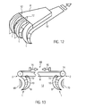
- Fig. 12 multiple manipulator tools 1 can be arranged side by side and operated independently or simultaneously with each other.
- the manipulator planes 12 may be parallel or intersect.
- the two cheeks 8, 10 can fan out in the manner of a finger, or the individual fingers can each be formed by a manipulator tool 1.
- the flexurally rigid cheek can have a high flexural rigidity or be rigidly formed in order to reduce or prevent deformation in this area and to limit the deformation essentially to the area of the fingers.
- the manipulator tool 1 can thus also be used as a gripping tool.
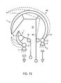
- Fig. 13 shows a further embodiment in which two manipulator tools 1 are arranged parallel to each other, wherein the proximal ends 2 arranged on a common tool base 4 and the at least rigid walls are associated with each other.
- Manipulator tools 1 lie in at least almost the same manipulator plane 12, in Fig. 13 the drawing plane.
- a spreading and / or gripping tool 66 which can be spread between two objects 68, 70 or in an opening of an object.
- a straight or mutually curved manipulator tools 1 are inserted between the objects 68, 70 and then the cheeks 10 driven longitudinally displaceable by acting on each cheek 10, a tensile force 16. Then the cheeks 8 curve in the direction of the objects 68, 70 and the holding and / or spreading tool wedges between the objects 68, 70th
- the two manipulator tools 1 can be arranged so as to be displaceable towards one another or away from one another along the tool base 4, so that the distance between the two manipulator tools 1 can be changed.
- the cheek 8 can be fastened to the tool base 4 via a hinge 72, so that when the pulling force 16 is applied, the cheek 8 initially moves substantially undeformed against the respectively associated object 68, 70 and only during further application of the pulling force during the movement Concerning the object 68, 70 curves.
- the cheek 10 or a pulling means connected to it can be deflected by a deflection roller 74.
- hinge 72 and the pulley 74 may also be used in any other embodiment described herein.
- FIGS. 14 and 15 show a further embodiment of a holding and / or Sp Dretzmaschinemaschinees, which is constructed of two manipulator tools 1, which are opposite to a gap 76, which serves for example to receive a workpiece.
- the at least tensile cheeks 10 face each other and define the gap 76.
- the gap 76 is open so that a workpiece (not shown) can be inserted from this side.
- the two cheeks 8 are fastened to the tool base 4 at the proximal end 2.
- the cheeks 10 are brought together at the proximal end 2 and end in a common traction means 78, so that they are actuated simultaneously in train.
- the course of the stiffness of the cheeks 8 in the direction from the proximal end 2 to the distal end 6 is selected such that a region 80 of reduced rigidity arises in the region of the proximal end of the intermediate space 76.
- This results in a train 16 ( Fig. 15 ) on the cheeks 10 the area 80 deforms more than the rest of the area of the cheek 8.
- the area 80 thus serves as an elastic joint around which distal ends 6 of the two manipulator tools 1 pivot.
- the region 80 of reduced stiffness can be done by a shaping, resulting in spikes in the material. Alternatively or additionally, this function can be achieved by reducing the wall thickness or by using a material of lower rigidity.
- the region 80 may be used instead of a hinge 72 when it comes to an elastic return function.
- the described holding and / or gripping function of the embodiment of Fig. 14 can be, as otherwise in the other embodiments also, in a simple manner in a spreading function, when the at least rigid cheeks 8 in the undeformed state, the in Fig. 14 occupy the position shown. Namely, the cheeks 8 are elastically deflected toward each other by the pulling force 16 and the width 82 of the holding and / or spreading tool decreases so that it can be inserted into an opening. If the tensile force is reduced, the cheeks 8 try again to spread elastically.
- the embodiment of the Fig. 16 differs from the embodiment of the FIGS. 14 and 15 by an articulated connection of the distal ends 6 of the two manipulator tools 1, so that an annularly closed interior 76 is formed.
- This embodiment is suitable in its basic form for spreading, but also for securely holding tubular objects.
- FIGS. 17 and 18 is a further example of a holding and / or spreading device 66 with two manipulator tools 1 shown. Also, this tool can be used depending on the initial curvature of the bending-resistant cheeks 8 either as a spreading and / or holding tool.
- the two cheeks 8 are in the embodiment of FIGS. 17 and 18 at a root 84, which may optionally be configured as a joint 72, connected to each other.
- the root 84 continues in a stem 86 which is connected to the tool base 4 at the proximal end 2.
- the two cheeks 8 run almost parallel to each other in the manipulator plane 12 and form between them the gap 76.
- the cheeks 8 move under magnification of the gap 76 away from each other.
- the holding and / or spreading tool in particular for example umbrella-like clamping or spreading of workpieces between the relative to the gap 76 opposite distal ends 6 of the two manipulator tools 1 suitable.
- Two manipulator tools 1 define a gap 76 with their cheeks 10 that are at least resistant to tension.
- the rigid cheeks 10 are connected by means of joints 72 to the tool base 4 at the proximal end 2 of the holding and / or spreading tool 66.
- the one manipulator tool 1 is significantly smaller than the other manipulator tool 1 and closes in the deformed state shown by solid lines the gap 76, while the larger manipulator tool 1 with its at least tensile cheek 10 sets out on the outside of the rigid cheek of the smaller tool.
- a holding and / or spreading tool 66 which may be made of sheet material by means of an injection molding, stamping or cutting process.
- Both cheeks 8, 10 of the two jaws 87 forming manipulator tools 1 are rigid, wherein the gap 76 facing cheeks 10 have a smaller wall thickness than the outer cheeks 8.
- the small wall thickness 8 also leads to greater flexibility of the cheeks 10, so that they are easier to place around gripping objects.
- the surface of the cheeks which performs the holding and / or spreading function can also be structured as required by the objects to be handled.
- the cheeks 10 a corrugation transverse to the longitudinal direction.
- the shear-movable connection via the at least one hinge element 20 is in the embodiment of the Fig. 20 achieved by the shaping in the region of the anchoring points 24, 30. Due to the almost rectangular connection of the elements 20 to the cheeks 8, 10 and in the region of the anchoring points 24, 30 slightly reduced wall thickness, the mobility is increased in the region of the anchoring points 24, 30, so that at these points a joint function is achieved.
- the outer cheeks 8 are connected via a hinge 72, which is produced by a weakening area in the form of an incision.
- the cheeks 8, 10 are joined together again to form an extension 48.
- the extension 48 allows a gentle gripping of objects.
- the cheeks 10 are integrally connected.
- a coupling element 88 for example in the form of an eyelet, may be provided.
- FIG. 20 shown tool 66 may at the end of a manipulator tool 1, as shown in the Fig. 1 to 6 is shown used.
- the tool base and the coupling 88 are interchanged or pressure forces are introduced at the coupling 88, then a spreading tool is created.
- Fig. 21 It is shown how, by the combination of two manipulator tools 1 according to the invention to form a holding and / or spreading tool 66, an article 68 can be adapted in a form-adaptive manner.
- the cheeks 10 engage the object 68 as a result of the pulling force 16 and adapt to its outer contour in the manipulator plane 12.
- the adaptation to the contour of the article 68 is also transferred to an extension 48, which is formed integrally with a reinforced at the distal end gripping region 90 on the inside of the cheeks 10.
- the shape adaptation can be connected to the outer cheek 8 and the rest of the cheek 10 by means of the hinged connection of the gripping area 90 via hinges 72 or areas 80 reduced flexural rigidity.
- Fig. 22 Fig. 4 shows how gripping area 90 can conform to the contour of another article 68 due to the hinged connection.
- FIG. 23 and 24 An embodiment of the holding and / or spreading tool 66, which is particularly suitable for endoscopic applications is in the Fig. 23 and 24 shown schematically.
- the holding and / or spreading tool is closed, in the Fig. 24 shown in a gripping position without gripped object.
- the holding and / or spreading tool 66 has three or more manipulator tools 1, which surround an inner space 76 in a star shape and which are mounted within a substantially circular outer contour.
- the holding and / or spreading tool 66 for example, in conjunction with endoscopes and push through them.
- the at least rigid cheeks 8 are fixedly clamped to the tool base 4.
- the clamping takes place here via elastically prestressed joints, which generate a cheeks 8 away from each other moving spring force.
- the at least tensile cheeks 10 face the gap 76.
- a tensile force 16 can be applied to the at least tensile cheeks 10.
- a pulling force 16 causes the manipulator tools 1 to be moved toward one another in an essentially undeformed manner against the spring force of the elastically prestressed joints and to prevent them from moving inwards Fig. 23 take shown position and can also be completely closed bud-shaped. However, this assumes that the stiffness in the joint is lower than the stiffness of the rigid cheeks. In the closed position, the embodiment of the Fig. 23 and 24 a slim cross-sectional shape, so that the gripping tool can be used especially in confined space situations, for example, as a fruit picker between branches or at the end of an endoscope between organs can be passed.
- the manipulator tools 1 are initially pivoted inwardly undeformed until they bear against the object when a tensile force is applied. Only the further longitudinal movement of the at least tensile cheeks 10 causes the in Fig. 2 shown deformation of Manipulatorwerkzeue endeavor. Biege stiff cheeks 8, which create the outer contour of the object.
- the manipulator tool 1 have a starting position in which it presses against the jaw 94.
- the outer cheek 10 By pulling on the outer cheek 10 it takes the in Fig. 25 shown position in which it is moved away from the opposite jaw 94, so that an object can be inserted into the gap 76.
- the design of the jaw 94 can be done depending on the desired function. With a suitable gripping function, the jaw 94 a contact surface for a in the space 76th train the object to be held. However, the jaw 94 may also be configured as a blade to cut through the article disposed in the gap 76 subject to a drop in tensile force 16. This is particularly useful in the field of vascular surgery when the in Fig. 25 shown holding and / or spreading tool is used for example in endoscopes.
- the embodiment of the Fig. 25 can be used in accordance with ergonomic design of the jaw 94 and the manipulator tool 1 as a handle that allows 16 to use other tools, not shown on the force.
- Fig. 26 shows a manipulator tool 1, which is used as an endoscope and threaded through between articles 68.
- the basic structure of such an endoscope can the structure of the embodiment of the FIGS. 5 and 6 correspond, in which the two cheeks 8, 10 are rigid and absorb both tensile and compressive forces, or one cheek 8 only compressive forces and the other cheek 10 only absorbs tensile forces.
- the distal end 6 of the manipulator tool 1 is free, by applying the forces 16, 18, the tip can be moved and placed around the objects 68 around. In this way, the distal end 6 can always be aligned so that it has between two adjacent objects 68, and the manipulator tool 1 can be interposed.
- a tool or an observation device attached to the distal end 6 may be repositioned about a last object 68, or this last object may be grasped, as indicated by the dashed line in FIG Fig. 26 is indicated.
- the hinge elements 20 are in Fig. 26 omitted for clarity.
- a central, rigid cheek 8 is divided by at least two cheeks 10 at least ten.
- the central bending-resistant cheek 8 is preferably held pivotably on the tool base 4.
- Each individual cheek 10 can be driven longitudinally displaceably at its proximal end 2.
- a curvature of the rigid cheek 8 can be achieved in the particular desired direction.
- the cheeks 10 may be arranged in more than one manipulator plane 12 and thus cause a three-dimensional curvature of the central cheek 8. Again, this is beneficial for endoscopic use.
- each opposing pairs of driven cheeks 10 are provided, the at least rigid cheek 8 must not be configured as a spring element, since the provision can be made by train on the opposite cheek 10.
- FIG. 28 to 30 Another embodiment, which allows a three-dimensional curvature of the manipulator tool 1 is in the Fig. 28 to 30 shown.
- a base area 96 of the tool base 4 in a circumferential direction 98 at least three, but preferably four cheeks 8, 10 are provided, which are connected in the circumferential direction, ie transversely to its longitudinal extent, by hinge elements 20.
- the cheeks 8, 10 are connected to a flexible sheath 102 which defines the structure to the outside and the cheeks 8, 10, the hinge elements 20 and the spacers 100 receives.
- This embodiment does not require that all cheeks 8, 10 are rigid.
- the number of bending walls which are at least necessary depends on the number of cheeks present in total in the manipulator tool 1 and on the number of bending-resistant cheeks necessary for shaping and rigidity.
- sheath 102 is of sufficient rigidity to support the cheeks 8, 10, they may also be segmented, i. H. be articulated by joints 104.
- the spacers 100 may extend anywhere between the cheeks, hinge members or hinges and the sheath 102.
- the hinge elements 20 may be substantially parallel to the envelope.
- the rigid cheek 8 is hollow and flexible, so that it can be inflated by a fluid 106 in its interior.
- the cheek 8 is limp when the fluid 106 is not under pressure, or is emptied.
- the manipulator tool 1 can thus be pushed through very small openings and then inflated.
- Embodiments 1 of the FIGS. 33 to 35 On the one hand, different embodiments of the connection of the at least rigid cheek 8 to the tool base 4 in the form of joints 72 in areas of reduced rigidity 80 are shown.
- the tool base 4 may have a knee 108, which serves as a guide for the loadable by a tensile force 16, at least tenable cheek 10.
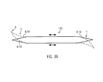
- Fig. 36 shows an embodiment in which at the ends of an elongated tool 110, two manipulator tools 1 are arranged, the cheeks 8, 10 are connected to each other, so that they are always operated simultaneously and in opposite directions.
- Fig. 37 shows an example of a section through such an embodiment.
- the tool base 4 is formed by an example polygonal base body, at the two opposite ends of the manipulator tools 1 are arranged.
- the area 112 between the two manipulator tools can be designed as a handle. If the tool base 4 is impressed with a shearing motion as a working movement, a tensile force or longitudinal movement is simultaneously introduced into one cheek of the one manipulator tool and a compressive force or longitudinal movement in the same direction into the cheek of the other manipulator tool on one side of the tool base. On the other side, there is a reverse direction of force. This results in a deformation of the manipulator tools 1 in the in Fig. 37 dashed form shown.
- Fig. 38 shows a handle 114 for the simultaneous generation of a compressive force 18 and a tensile force 16 in a manipulator tool 1, not shown, which is connected to the tension / pressure means 116.
- the handle 14 is articulated and can, as indicated by the arrow 118, be tilted.
- a compressive force is generated, the pulling force 16 being directed away from the tilting direction.
- the bearing of the handle 108 is preferably carried out at a location which is rigidly connected to the tool base 4.
- Fig. 39 shows the embodiment of a manipulator tool 1 in tube form.
- the interior 120 at least freely opens at the proximal end 2 and thus suitable for receiving other instruments or for the passage of fluids, adjacent cheeks 8, 10 are not wedge-shaped at its distal end 6, but bluntly connected by a respective end member 122.
- the use of such a closure element 122 is irrelevant to the effect according to the invention, as long as in the case of the wedge-shaped connection point 14 (FIG. Fig. 1 ) ensures that the angles between the adjacent cheeks 8, 10, which are connected to each other at this point, not or only insignificantly change in the deformation.
- the movable cheeks of a development at the proximal end can be connected by a rigid ring, on the movement of which in particular tilting the deformation of the tube is effected by the attached cheeks are moved simultaneously.
- the tube can be used as a separate instrument, for example as a movable tube.
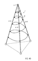
- the shape of the hinge elements 20 is as long as they have their with respect to the Fig. 2 fulfill described function, determined primarily by the application of the manipulator tool 1.
- a continuous hinge element extending helically between a plurality of cheeks 8, 10, such as Fig. 40 shows.
- circles as in Fig. 39 or other geometric configurations are used.
- the at least rigid cheek 8 itself can be hollow and serve as a tool holder for therein longitudinally displaceable recorded tools. This is in the FIGS. 41 to 43 shown.
- tools such as a blade 124, a needle 126 or a loop 128 may be received in the rigid cheek 8.
- fluids can be passed or electrical or optical devices recorded.
- Fig. 44 shows that at the distal end 6, the connection between the cheeks 8, 10 need not be wedge-shaped, but also blunt by the closing element 122, which may be formed, for example, integral with the at least rigid cheek 10 takes place. All that is essential is that at the distal end 6 there is a triangular figure that is essentially angularly stable over the deformation of the manipulator tool 1, which in FIG Fig. 44 indicated by the dot-dash line.
Applications Claiming Priority (1)
| Application Number | Priority Date | Filing Date | Title |
|---|---|---|---|
| DE102009017591A DE102009017591A1 (de) | 2009-04-19 | 2009-04-19 | Manipulatorwerkzeug und Halt- und/oder Spreizwerkzeug mit wengistens einem Manipulatorwerkzeug |
Publications (2)
| Publication Number | Publication Date |
|---|---|
| EP2241403A1 true EP2241403A1 (fr) | 2010-10-20 |
| EP2241403B1 EP2241403B1 (fr) | 2019-02-27 |
Family
ID=42224417
Family Applications (1)
| Application Number | Title | Priority Date | Filing Date |
|---|---|---|---|
| EP10002411.6A Active EP2241403B1 (fr) | 2009-04-19 | 2010-03-09 | Outil de manipulation et outil pour fixer et/ou écarter avec au moins un outil de manipulation |
Country Status (3)
| Country | Link |
|---|---|
| US (1) | US8333417B2 (fr) |
| EP (1) | EP2241403B1 (fr) |
| DE (1) | DE102009017591A1 (fr) |
Cited By (10)
| Publication number | Priority date | Publication date | Assignee | Title |
|---|---|---|---|---|
| EP2502714A1 (fr) * | 2011-03-23 | 2012-09-26 | Festo AG & Co. KG | Dispositif de retenue pour la retenue d'objets |
| CN104669292A (zh) * | 2015-03-28 | 2015-06-03 | 哈尔滨工业大学 | 一种有凸起气囊的螺旋缠绕式充气抓捕手 |
| EP3150518A1 (fr) * | 2015-10-01 | 2017-04-05 | Deutsche Post AG | Procédé et dispositif de convoyage de marchandises depuis une pile ou un tas |
| DE102016113498A1 (de) | 2016-07-21 | 2018-01-25 | Karl Storz Gmbh & Co. Kg | Adaptives Laryngoskop und adaptiver Spatel für ein Laryngoskop |
| EP2735406B1 (fr) * | 2012-11-27 | 2018-04-04 | FESTO AG & Co. KG | Dispositif de saisie destiné à saisir des objets |
| DE102017102089A1 (de) | 2017-02-02 | 2018-08-02 | Karl Storz Se & Co. Kg | Laryngoskop und adaptiver Spatel für ein Laryngoskop |
| DE102019002892A1 (de) * | 2019-04-23 | 2020-10-29 | Kuka Deutschland Gmbh | Werkzeug sowie Greifer aufweisend ein Werkzeug |
| CN112441409A (zh) * | 2019-09-05 | 2021-03-05 | 克朗斯股份公司 | 容器抓取器和容器运输设备 |
| EP3929123A1 (fr) * | 2020-06-26 | 2021-12-29 | Deutsche Post AG | Procédé et dispositif de déchargement d'un récipient contenant des colis |
| EP3981718A1 (fr) * | 2020-10-08 | 2022-04-13 | Deutsche Post AG | Procédé et dispositif de chargement de récipients comportant des colis |
Families Citing this family (33)
| Publication number | Priority date | Publication date | Assignee | Title |
|---|---|---|---|---|
| US8156995B2 (en) * | 2009-04-20 | 2012-04-17 | Rite-Hite Holding Corporation | Door element |
| DE102010009259A1 (de) * | 2010-02-25 | 2011-08-25 | Karl Storz GmbH & Co. KG, 78532 | Medizinisches Instrument |
| DE102010022431A1 (de) * | 2010-06-01 | 2011-12-01 | Karl Storz Gmbh & Co. Kg | Medizinisches Greifwerkzeug |
| US20120261113A1 (en) * | 2011-04-12 | 2012-10-18 | Langevin Levi C | Cobble/small boulder debris device in borehole excavating |
| CN102601799A (zh) * | 2012-03-30 | 2012-07-25 | 北京工业大学 | 自适应于夹持对象外形的柔性机械手指 |
| US9162832B2 (en) | 2013-07-02 | 2015-10-20 | Rite-Hite Holding Corporation | Vehicle-actuated weather barrier apparatus |
| DE102013107972A1 (de) | 2013-07-25 | 2015-02-19 | Karl Storz Gmbh & Co. Kg | Medizinisches Greifwerkzeug |
| JP5681271B1 (ja) | 2013-07-26 | 2015-03-04 | ファナック株式会社 | ロボット用把持装置 |
| US9238302B2 (en) | 2013-12-02 | 2016-01-19 | David Allen Thibodeaux | Reaching aid apparatus |
| US9575319B2 (en) | 2014-03-10 | 2017-02-21 | Ion Virtual Technology Corporation | Method and system for reducing motion blur when experiencing virtual or augmented reality environments |
| US9529200B2 (en) | 2014-03-10 | 2016-12-27 | Ion Virtual Technology Corporation | Method and system for reducing motion blur when experiencing virtual or augmented reality environments |
| US10208925B2 (en) | 2014-03-11 | 2019-02-19 | Soft Robotics, Inc. | Soft conformal laparoscopic instrument |
| US10219817B2 (en) | 2014-03-13 | 2019-03-05 | Lsi Solutions, Inc. | Surgical clamp and clamp jaw |
| NL2013982B1 (en) * | 2014-12-15 | 2016-10-11 | Univ Delft Tech | Grasper. |
| US9829711B2 (en) | 2014-12-18 | 2017-11-28 | Ion Virtual Technology Corporation | Inflatable virtual reality headset system |
| CN107530887B (zh) | 2015-03-05 | 2020-11-20 | 哈佛大学董事会 | 机器人抓握器、联动装置及用于机器人抓握的方法 |
| US20210315559A1 (en) * | 2015-03-07 | 2021-10-14 | Hagay Drori | Manipulating device with tube wall formations |
| JP2017001113A (ja) * | 2015-06-05 | 2017-01-05 | アルパイン株式会社 | 把持装置 |
| CN108290284B (zh) * | 2015-07-30 | 2019-07-12 | 软机器人公司 | 独立型机器人抓持器系统 |
| DE102015114556A1 (de) * | 2015-09-01 | 2017-03-02 | Röhm Gmbh | Greifer und Verfahren zur Herstellung eines Greifers |
| US9533419B1 (en) | 2015-11-02 | 2017-01-03 | Google Inc. | Robotic finger and hand |
| CN112969559B (zh) * | 2018-10-30 | 2022-06-07 | 西门子股份公司 | 具有弯曲间隔元件的夹持指和自适应夹持装置 |
| DE102019003714B4 (de) * | 2019-05-25 | 2021-05-06 | Festo Se & Co. Kg | einstückig ausgelbidete Greifvorrichtung mit Stütz- und Biegearmen |
| JP7182041B2 (ja) * | 2019-08-15 | 2022-12-02 | パナソニックIpマネジメント株式会社 | ロボットハンド |
| CN110539262A (zh) * | 2019-09-06 | 2019-12-06 | 佛山科学技术学院 | 一种平行驱动的柔顺欠驱动夹持器 |
| US11896250B2 (en) | 2020-08-31 | 2024-02-13 | Covidien Lp | Aspiration systems and methods, and expanding-mouth catheters |
| DE102020215228B3 (de) | 2020-12-02 | 2022-03-17 | Festo Se & Co. Kg | Greifvorrichtung zum Greifen von Objekten und Verfahren zum Betreiben einer solchen Greifvorrichtung |
| KR102464327B1 (ko) * | 2021-03-31 | 2022-11-09 | 한국기계연구원 | 이방성 표면장력을 갖는 그리퍼 |
| CN113442152B (zh) * | 2021-06-24 | 2022-07-05 | 华南农业大学 | 一种用于水果采摘并具有侧向包裹性的柔性手指 |
| CN114161469B (zh) * | 2021-10-20 | 2024-03-26 | 华中农业大学 | 基于抓感一体化的无损水果卡爪 |
| CN114102337A (zh) * | 2021-11-24 | 2022-03-01 | 重庆佳鑫一帆科技有限公司 | 一种塑料工件的斜边打磨设备 |
| WO2023209478A1 (fr) * | 2022-04-27 | 2023-11-02 | C.R.F. Società Consortile Per Azioni | "dispositif de préhension permettant de manipuler des pièces ou des composants présentant des formes et des tailles variables" |
| CN116604596A (zh) * | 2023-04-21 | 2023-08-18 | 广东省科学院智能制造研究所 | 一种刚柔耦合机器人手爪 |
Citations (10)
| Publication number | Priority date | Publication date | Assignee | Title |
|---|---|---|---|---|
| FR545837A (fr) * | 1922-01-09 | 1922-10-21 | C & E Streisguth | Main artificielle |
| US4719826A (en) * | 1986-06-02 | 1988-01-19 | Dubois Roger D | Light bulb extractor |
| EP1040999A2 (fr) | 1999-04-01 | 2000-10-04 | Leif Kniese | Elément de support de charges avec enveloppe extérieure souple |
| DE20318845U1 (de) * | 2003-12-02 | 2004-03-25 | Grießbach, Volker, Dr.-Ing. | Handhabevorrichtung für dreidimensionale Objekte |
| US20040183348A1 (en) * | 2003-03-19 | 2004-09-23 | Leif Kniese | Seating element |
| DE102005010380A1 (de) * | 2005-03-07 | 2006-09-14 | Fraunhofer-Gesellschaft zur Förderung der angewandten Forschung e.V. | Greifwerkzeug mit selbstadaptiver Kinematik |
| DE102006009559B3 (de) * | 2006-02-28 | 2007-05-31 | Fraunhofer-Gesellschaft zur Förderung der angewandten Forschung e.V. | Greifervorrichtung sowie Verfahren zu deren Herstellung |
| DE102007026721A1 (de) * | 2006-06-09 | 2008-05-15 | Fachhochschule Münster | Werkzeug zum Greifen, Halten, Bearbeiten oder Untersuchen von Körperbestandteilen |
| WO2008128780A1 (fr) | 2007-04-18 | 2008-10-30 | Rudolf Bannasch | Pale battante courbée et dispositif d'entraînement pour une pale battante courbée |
| WO2009039231A2 (fr) * | 2007-09-20 | 2009-03-26 | Herman Miller, Inc. | Structure de support de charge |
Family Cites Families (9)
| Publication number | Priority date | Publication date | Assignee | Title |
|---|---|---|---|---|
| US2545452A (en) * | 1946-10-01 | 1951-03-20 | Maurice J Fletcher | Segmented articulated finger |
| US2549257A (en) * | 1949-11-04 | 1951-04-17 | Staunt Martin | Golf ball retriever |
| US3527492A (en) * | 1968-06-25 | 1970-09-08 | Jimmy L Davis | Trash pick-up device |
| US5356187A (en) * | 1993-06-21 | 1994-10-18 | The United States Of America As Represented By The Secretary Of The Navy | Recovery and deployment device |
| US5522290A (en) * | 1994-04-18 | 1996-06-04 | Visser; Steven C. | Compliant pliers |
| DE19537320C2 (de) | 1995-10-06 | 2001-05-31 | Deutsch Zentr Luft & Raumfahrt | Greifvorrichtung für einen Einsatz vorzugsweise in der minimal invasiven Chirurgie und Vorrichtung zum Betätigen einer am distalen Ende eines Einführungsrohrs vorgesehenen Greifvorrichtung |
| GB0015113D0 (en) * | 2000-06-20 | 2000-08-09 | Angiomed Ag | Tool for removing object from the body of a patient |
| ATE555877T1 (de) | 2000-11-01 | 2012-05-15 | Leif Kniese | Vorrichtung zur aufnahme von kräften, mit einer flexiblen aussenhaut |
| US8156995B2 (en) * | 2009-04-20 | 2012-04-17 | Rite-Hite Holding Corporation | Door element |
-
2009
- 2009-04-19 DE DE102009017591A patent/DE102009017591A1/de not_active Withdrawn
-
2010
- 2010-03-09 EP EP10002411.6A patent/EP2241403B1/fr active Active
- 2010-04-19 US US12/762,962 patent/US8333417B2/en active Active
Patent Citations (10)
| Publication number | Priority date | Publication date | Assignee | Title |
|---|---|---|---|---|
| FR545837A (fr) * | 1922-01-09 | 1922-10-21 | C & E Streisguth | Main artificielle |
| US4719826A (en) * | 1986-06-02 | 1988-01-19 | Dubois Roger D | Light bulb extractor |
| EP1040999A2 (fr) | 1999-04-01 | 2000-10-04 | Leif Kniese | Elément de support de charges avec enveloppe extérieure souple |
| US20040183348A1 (en) * | 2003-03-19 | 2004-09-23 | Leif Kniese | Seating element |
| DE20318845U1 (de) * | 2003-12-02 | 2004-03-25 | Grießbach, Volker, Dr.-Ing. | Handhabevorrichtung für dreidimensionale Objekte |
| DE102005010380A1 (de) * | 2005-03-07 | 2006-09-14 | Fraunhofer-Gesellschaft zur Förderung der angewandten Forschung e.V. | Greifwerkzeug mit selbstadaptiver Kinematik |
| DE102006009559B3 (de) * | 2006-02-28 | 2007-05-31 | Fraunhofer-Gesellschaft zur Förderung der angewandten Forschung e.V. | Greifervorrichtung sowie Verfahren zu deren Herstellung |
| DE102007026721A1 (de) * | 2006-06-09 | 2008-05-15 | Fachhochschule Münster | Werkzeug zum Greifen, Halten, Bearbeiten oder Untersuchen von Körperbestandteilen |
| WO2008128780A1 (fr) | 2007-04-18 | 2008-10-30 | Rudolf Bannasch | Pale battante courbée et dispositif d'entraînement pour une pale battante courbée |
| WO2009039231A2 (fr) * | 2007-09-20 | 2009-03-26 | Herman Miller, Inc. | Structure de support de charge |
Cited By (15)
| Publication number | Priority date | Publication date | Assignee | Title |
|---|---|---|---|---|
| EP2502714A1 (fr) * | 2011-03-23 | 2012-09-26 | Festo AG & Co. KG | Dispositif de retenue pour la retenue d'objets |
| EP2735406B1 (fr) * | 2012-11-27 | 2018-04-04 | FESTO AG & Co. KG | Dispositif de saisie destiné à saisir des objets |
| CN104669292A (zh) * | 2015-03-28 | 2015-06-03 | 哈尔滨工业大学 | 一种有凸起气囊的螺旋缠绕式充气抓捕手 |
| CN104669292B (zh) * | 2015-03-28 | 2016-04-27 | 哈尔滨工业大学 | 一种有凸起气囊的螺旋缠绕式充气抓捕手 |
| US10035657B2 (en) | 2015-10-01 | 2018-07-31 | Deutsche Post Ag | Method and device for conveying piece goods from a stack or pile |
| EP3150518A1 (fr) * | 2015-10-01 | 2017-04-05 | Deutsche Post AG | Procédé et dispositif de convoyage de marchandises depuis une pile ou un tas |
| DE102016113498A1 (de) | 2016-07-21 | 2018-01-25 | Karl Storz Gmbh & Co. Kg | Adaptives Laryngoskop und adaptiver Spatel für ein Laryngoskop |
| DE102017102089A1 (de) | 2017-02-02 | 2018-08-02 | Karl Storz Se & Co. Kg | Laryngoskop und adaptiver Spatel für ein Laryngoskop |
| US10791912B2 (en) | 2017-02-02 | 2020-10-06 | Karl Storz Se & Co. Kg | Laryngoscope and adaptive blade for a laryngoscope |
| DE102019002892A1 (de) * | 2019-04-23 | 2020-10-29 | Kuka Deutschland Gmbh | Werkzeug sowie Greifer aufweisend ein Werkzeug |
| CN112441409A (zh) * | 2019-09-05 | 2021-03-05 | 克朗斯股份公司 | 容器抓取器和容器运输设备 |
| EP3789323A1 (fr) * | 2019-09-05 | 2021-03-10 | Krones Ag | Préhenseur de récipient et dispositif de transport de récipients |
| EP3929123A1 (fr) * | 2020-06-26 | 2021-12-29 | Deutsche Post AG | Procédé et dispositif de déchargement d'un récipient contenant des colis |
| EP3981718A1 (fr) * | 2020-10-08 | 2022-04-13 | Deutsche Post AG | Procédé et dispositif de chargement de récipients comportant des colis |
| US11613436B2 (en) | 2020-10-08 | 2023-03-28 | Deutsche Post Ag | Method and device for loading containers with packages |
Also Published As
| Publication number | Publication date |
|---|---|
| US20100263500A1 (en) | 2010-10-21 |
| DE102009017591A1 (de) | 2010-10-21 |
| EP2241403B1 (fr) | 2019-02-27 |
| US8333417B2 (en) | 2012-12-18 |
Similar Documents
| Publication | Publication Date | Title |
|---|---|---|
| EP2241403B1 (fr) | Outil de manipulation et outil pour fixer et/ou écarter avec au moins un outil de manipulation | |
| EP2874548B1 (fr) | Instrument endoscopique | |
| EP2877100B1 (fr) | Tige pour instrument médical comprenant des sections mobiles | |
| DE3390015C2 (de) | Schaftanordnung f}r ein chirurgisches Klammerinstrument | |
| EP2829239B1 (fr) | Appareil de préhension médical | |
| EP2612609B1 (fr) | Instrument médical | |
| DE202009001951U1 (de) | Medizinisches Instrument | |
| WO2015165873A1 (fr) | Instrument en forme de tige à usage médical présentant une capacité de déformation dans la partie formant mâchoire et système constitué d'un instrument en forme de tige et d'agrafe(s) | |
| EP1891853A1 (fr) | Appareil de travail pouvant être tenu à la main, en particulier dispositif de découpe de branches | |
| DE202008001675U1 (de) | Zerlegbares chirurgisches Instrument | |
| DE102014100603A1 (de) | Chirurgischer Handgriff für ein Rohrschaftwerkzeug | |
| WO2020094188A1 (fr) | Instrument endoscopique | |
| DE4412171A1 (de) | Chirurgisches Instrument | |
| DE102009037613A1 (de) | Elektrochirurgisches Instrument | |
| WO2021244938A1 (fr) | Doigts de préhension et pince munie de tels doigts de préhension | |
| DE102015204486B4 (de) | Chirurgisches Instrument | |
| DE102013012802A1 (de) | Chirurgisches Instrument | |
| EP3578118B1 (fr) | Instrument chirurgical | |
| EP3266393A1 (fr) | Instrument chirurgical | |
| EP2253282B1 (fr) | Manipulateur d'endoscopie | |
| WO2001083130A1 (fr) | Dispositif de cintrage de tubes metalliques a parois minces | |
| WO2018036654A1 (fr) | Outil pour éliminer et/ou couper les poils | |
| DE102009055351A1 (de) | Steuerung eines rohrförmigen Schafts eines chirurgischen Instruments | |
| DE10136963B4 (de) | Chirurgisches Instrument | |
| DE4236738C1 (de) | Zangen- oder spreizerförmiges, ärztliches Instrument |
Legal Events
| Date | Code | Title | Description |
|---|---|---|---|
| PUAI | Public reference made under article 153(3) epc to a published international application that has entered the european phase |
Free format text: ORIGINAL CODE: 0009012 |
|
| AK | Designated contracting states |
Kind code of ref document: A1 Designated state(s): AT BE BG CH CY CZ DE DK EE ES FI FR GB GR HR HU IE IS IT LI LT LU LV MC MK MT NL NO PL PT RO SE SI SK SM TR |
|
| AX | Request for extension of the european patent |
Extension state: AL BA ME RS |
|
| 17P | Request for examination filed |
Effective date: 20110418 |
|
| 17Q | First examination report despatched |
Effective date: 20140902 |
|
| RAP1 | Party data changed (applicant data changed or rights of an application transferred) |
Owner name: KARL STORZ SE & CO. KG Owner name: KNIESE, LEIF Owner name: BANNASCH, RUDOLF |
|
| GRAP | Despatch of communication of intention to grant a patent |
Free format text: ORIGINAL CODE: EPIDOSNIGR1 |
|
| STAA | Information on the status of an ep patent application or granted ep patent |
Free format text: STATUS: GRANT OF PATENT IS INTENDED |
|
| RIC1 | Information provided on ipc code assigned before grant |
Ipc: A61B 17/02 20060101ALI20180423BHEP Ipc: A61B 17/221 20060101ALI20180423BHEP Ipc: B25B 9/00 20060101ALI20180423BHEP Ipc: A61B 17/30 20060101ALI20180423BHEP Ipc: B25J 15/10 20060101ALI20180423BHEP Ipc: A61B 17/22 20060101ALI20180423BHEP Ipc: B25B 7/02 20060101AFI20180423BHEP Ipc: A61B 17/34 20060101ALI20180423BHEP Ipc: A61B 17/00 20060101ALI20180423BHEP Ipc: A61B 10/06 20060101ALI20180423BHEP Ipc: A61B 17/29 20060101ALI20180423BHEP |
|
| INTG | Intention to grant announced |
Effective date: 20180511 |
|
| GRAJ | Information related to disapproval of communication of intention to grant by the applicant or resumption of examination proceedings by the epo deleted |
Free format text: ORIGINAL CODE: EPIDOSDIGR1 |
|
| STAA | Information on the status of an ep patent application or granted ep patent |
Free format text: STATUS: EXAMINATION IS IN PROGRESS |
|
| GRAP | Despatch of communication of intention to grant a patent |
Free format text: ORIGINAL CODE: EPIDOSNIGR1 |
|
| STAA | Information on the status of an ep patent application or granted ep patent |
Free format text: STATUS: GRANT OF PATENT IS INTENDED |
|
| INTC | Intention to grant announced (deleted) | ||
| INTG | Intention to grant announced |
Effective date: 20180802 |
|
| GRAJ | Information related to disapproval of communication of intention to grant by the applicant or resumption of examination proceedings by the epo deleted |
Free format text: ORIGINAL CODE: EPIDOSDIGR1 |
|
| STAA | Information on the status of an ep patent application or granted ep patent |
Free format text: STATUS: EXAMINATION IS IN PROGRESS |
|
| GRAP | Despatch of communication of intention to grant a patent |
Free format text: ORIGINAL CODE: EPIDOSNIGR1 |
|
| STAA | Information on the status of an ep patent application or granted ep patent |
Free format text: STATUS: GRANT OF PATENT IS INTENDED |
|
| INTC | Intention to grant announced (deleted) | ||
| INTG | Intention to grant announced |
Effective date: 20180919 |
|
| GRAS | Grant fee paid |
Free format text: ORIGINAL CODE: EPIDOSNIGR3 |
|
| GRAA | (expected) grant |
Free format text: ORIGINAL CODE: 0009210 |
|
| STAA | Information on the status of an ep patent application or granted ep patent |
Free format text: STATUS: THE PATENT HAS BEEN GRANTED |
|
| AK | Designated contracting states |
Kind code of ref document: B1 Designated state(s): AT BE BG CH CY CZ DE DK EE ES FI FR GB GR HR HU IE IS IT LI LT LU LV MC MK MT NL NO PL PT RO SE SI SK SM TR |
|
| REG | Reference to a national code |
Ref country code: GB Ref legal event code: FG4D Free format text: NOT ENGLISH |
|
| REG | Reference to a national code |
Ref country code: CH Ref legal event code: EP |
|
| REG | Reference to a national code |
Ref country code: DE Ref legal event code: R096 Ref document number: 502010015803 Country of ref document: DE |
|
| REG | Reference to a national code |
Ref country code: AT Ref legal event code: REF Ref document number: 1100640 Country of ref document: AT Kind code of ref document: T Effective date: 20190315 |
|
| REG | Reference to a national code |
Ref country code: IE Ref legal event code: FG4D Free format text: LANGUAGE OF EP DOCUMENT: GERMAN |
|
| REG | Reference to a national code |
Ref country code: NL Ref legal event code: MP Effective date: 20190227 |
|
| REG | Reference to a national code |
Ref country code: LT Ref legal event code: MG4D |
|
| PG25 | Lapsed in a contracting state [announced via postgrant information from national office to epo] |
Ref country code: NL Free format text: LAPSE BECAUSE OF FAILURE TO SUBMIT A TRANSLATION OF THE DESCRIPTION OR TO PAY THE FEE WITHIN THE PRESCRIBED TIME-LIMIT Effective date: 20190227 Ref country code: PT Free format text: LAPSE BECAUSE OF FAILURE TO SUBMIT A TRANSLATION OF THE DESCRIPTION OR TO PAY THE FEE WITHIN THE PRESCRIBED TIME-LIMIT Effective date: 20190627 Ref country code: SE Free format text: LAPSE BECAUSE OF FAILURE TO SUBMIT A TRANSLATION OF THE DESCRIPTION OR TO PAY THE FEE WITHIN THE PRESCRIBED TIME-LIMIT Effective date: 20190227 Ref country code: LT Free format text: LAPSE BECAUSE OF FAILURE TO SUBMIT A TRANSLATION OF THE DESCRIPTION OR TO PAY THE FEE WITHIN THE PRESCRIBED TIME-LIMIT Effective date: 20190227 Ref country code: NO Free format text: LAPSE BECAUSE OF FAILURE TO SUBMIT A TRANSLATION OF THE DESCRIPTION OR TO PAY THE FEE WITHIN THE PRESCRIBED TIME-LIMIT Effective date: 20190527 Ref country code: FI Free format text: LAPSE BECAUSE OF FAILURE TO SUBMIT A TRANSLATION OF THE DESCRIPTION OR TO PAY THE FEE WITHIN THE PRESCRIBED TIME-LIMIT Effective date: 20190227 |
|
| PG25 | Lapsed in a contracting state [announced via postgrant information from national office to epo] |
Ref country code: IS Free format text: LAPSE BECAUSE OF FAILURE TO SUBMIT A TRANSLATION OF THE DESCRIPTION OR TO PAY THE FEE WITHIN THE PRESCRIBED TIME-LIMIT Effective date: 20190627 Ref country code: BG Free format text: LAPSE BECAUSE OF FAILURE TO SUBMIT A TRANSLATION OF THE DESCRIPTION OR TO PAY THE FEE WITHIN THE PRESCRIBED TIME-LIMIT Effective date: 20190527 Ref country code: HR Free format text: LAPSE BECAUSE OF FAILURE TO SUBMIT A TRANSLATION OF THE DESCRIPTION OR TO PAY THE FEE WITHIN THE PRESCRIBED TIME-LIMIT Effective date: 20190227 Ref country code: LV Free format text: LAPSE BECAUSE OF FAILURE TO SUBMIT A TRANSLATION OF THE DESCRIPTION OR TO PAY THE FEE WITHIN THE PRESCRIBED TIME-LIMIT Effective date: 20190227 Ref country code: GR Free format text: LAPSE BECAUSE OF FAILURE TO SUBMIT A TRANSLATION OF THE DESCRIPTION OR TO PAY THE FEE WITHIN THE PRESCRIBED TIME-LIMIT Effective date: 20190528 |
|
| PG25 | Lapsed in a contracting state [announced via postgrant information from national office to epo] |
Ref country code: ES Free format text: LAPSE BECAUSE OF FAILURE TO SUBMIT A TRANSLATION OF THE DESCRIPTION OR TO PAY THE FEE WITHIN THE PRESCRIBED TIME-LIMIT Effective date: 20190227 Ref country code: SK Free format text: LAPSE BECAUSE OF FAILURE TO SUBMIT A TRANSLATION OF THE DESCRIPTION OR TO PAY THE FEE WITHIN THE PRESCRIBED TIME-LIMIT Effective date: 20190227 Ref country code: EE Free format text: LAPSE BECAUSE OF FAILURE TO SUBMIT A TRANSLATION OF THE DESCRIPTION OR TO PAY THE FEE WITHIN THE PRESCRIBED TIME-LIMIT Effective date: 20190227 Ref country code: DK Free format text: LAPSE BECAUSE OF FAILURE TO SUBMIT A TRANSLATION OF THE DESCRIPTION OR TO PAY THE FEE WITHIN THE PRESCRIBED TIME-LIMIT Effective date: 20190227 Ref country code: RO Free format text: LAPSE BECAUSE OF FAILURE TO SUBMIT A TRANSLATION OF THE DESCRIPTION OR TO PAY THE FEE WITHIN THE PRESCRIBED TIME-LIMIT Effective date: 20190227 Ref country code: CZ Free format text: LAPSE BECAUSE OF FAILURE TO SUBMIT A TRANSLATION OF THE DESCRIPTION OR TO PAY THE FEE WITHIN THE PRESCRIBED TIME-LIMIT Effective date: 20190227 |
|
| REG | Reference to a national code |
Ref country code: CH Ref legal event code: PL |
|
| REG | Reference to a national code |
Ref country code: DE Ref legal event code: R097 Ref document number: 502010015803 Country of ref document: DE |
|
| PG25 | Lapsed in a contracting state [announced via postgrant information from national office to epo] |
Ref country code: LU Free format text: LAPSE BECAUSE OF NON-PAYMENT OF DUE FEES Effective date: 20190309 Ref country code: SM Free format text: LAPSE BECAUSE OF FAILURE TO SUBMIT A TRANSLATION OF THE DESCRIPTION OR TO PAY THE FEE WITHIN THE PRESCRIBED TIME-LIMIT Effective date: 20190227 Ref country code: PL Free format text: LAPSE BECAUSE OF FAILURE TO SUBMIT A TRANSLATION OF THE DESCRIPTION OR TO PAY THE FEE WITHIN THE PRESCRIBED TIME-LIMIT Effective date: 20190227 |
|
| REG | Reference to a national code |
Ref country code: BE Ref legal event code: MM Effective date: 20190331 |
|
| PG25 | Lapsed in a contracting state [announced via postgrant information from national office to epo] |
Ref country code: MC Free format text: LAPSE BECAUSE OF FAILURE TO SUBMIT A TRANSLATION OF THE DESCRIPTION OR TO PAY THE FEE WITHIN THE PRESCRIBED TIME-LIMIT Effective date: 20190227 |
|
| PLBE | No opposition filed within time limit |
Free format text: ORIGINAL CODE: 0009261 |
|
| STAA | Information on the status of an ep patent application or granted ep patent |
Free format text: STATUS: NO OPPOSITION FILED WITHIN TIME LIMIT |
|
| PG25 | Lapsed in a contracting state [announced via postgrant information from national office to epo] |
Ref country code: CH Free format text: LAPSE BECAUSE OF NON-PAYMENT OF DUE FEES Effective date: 20190331 Ref country code: LI Free format text: LAPSE BECAUSE OF NON-PAYMENT OF DUE FEES Effective date: 20190331 Ref country code: IE Free format text: LAPSE BECAUSE OF NON-PAYMENT OF DUE FEES Effective date: 20190309 |
|
| 26N | No opposition filed |
Effective date: 20191128 |
|
| PG25 | Lapsed in a contracting state [announced via postgrant information from national office to epo] |
Ref country code: SI Free format text: LAPSE BECAUSE OF FAILURE TO SUBMIT A TRANSLATION OF THE DESCRIPTION OR TO PAY THE FEE WITHIN THE PRESCRIBED TIME-LIMIT Effective date: 20190227 Ref country code: BE Free format text: LAPSE BECAUSE OF NON-PAYMENT OF DUE FEES Effective date: 20190331 |
|
| PG25 | Lapsed in a contracting state [announced via postgrant information from national office to epo] |
Ref country code: TR Free format text: LAPSE BECAUSE OF FAILURE TO SUBMIT A TRANSLATION OF THE DESCRIPTION OR TO PAY THE FEE WITHIN THE PRESCRIBED TIME-LIMIT Effective date: 20190227 |
|
| PG25 | Lapsed in a contracting state [announced via postgrant information from national office to epo] |
Ref country code: MT Free format text: LAPSE BECAUSE OF FAILURE TO SUBMIT A TRANSLATION OF THE DESCRIPTION OR TO PAY THE FEE WITHIN THE PRESCRIBED TIME-LIMIT Effective date: 20190227 |
|
| REG | Reference to a national code |
Ref country code: AT Ref legal event code: MM01 Ref document number: 1100640 Country of ref document: AT Kind code of ref document: T Effective date: 20190309 |
|
| PG25 | Lapsed in a contracting state [announced via postgrant information from national office to epo] |
Ref country code: AT Free format text: LAPSE BECAUSE OF NON-PAYMENT OF DUE FEES Effective date: 20190309 |
|
| PG25 | Lapsed in a contracting state [announced via postgrant information from national office to epo] |
Ref country code: CY Free format text: LAPSE BECAUSE OF FAILURE TO SUBMIT A TRANSLATION OF THE DESCRIPTION OR TO PAY THE FEE WITHIN THE PRESCRIBED TIME-LIMIT Effective date: 20190227 |
|
| PG25 | Lapsed in a contracting state [announced via postgrant information from national office to epo] |
Ref country code: HU Free format text: LAPSE BECAUSE OF FAILURE TO SUBMIT A TRANSLATION OF THE DESCRIPTION OR TO PAY THE FEE WITHIN THE PRESCRIBED TIME-LIMIT; INVALID AB INITIO Effective date: 20100309 |
|
| PG25 | Lapsed in a contracting state [announced via postgrant information from national office to epo] |
Ref country code: MK Free format text: LAPSE BECAUSE OF FAILURE TO SUBMIT A TRANSLATION OF THE DESCRIPTION OR TO PAY THE FEE WITHIN THE PRESCRIBED TIME-LIMIT Effective date: 20190227 |
|
| PGFP | Annual fee paid to national office [announced via postgrant information from national office to epo] |
Ref country code: FR Payment date: 20230322 Year of fee payment: 14 |
|
| PGFP | Annual fee paid to national office [announced via postgrant information from national office to epo] |
Ref country code: GB Payment date: 20230322 Year of fee payment: 14 Ref country code: DE Payment date: 20230323 Year of fee payment: 14 |
|
| PGFP | Annual fee paid to national office [announced via postgrant information from national office to epo] |
Ref country code: IT Payment date: 20230331 Year of fee payment: 14 |
|
| P01 | Opt-out of the competence of the unified patent court (upc) registered |
Effective date: 20230808 |