EP2241403A1 - Manipulator tool and holding and/or widening tool with at least one manipulator tool - Google Patents
Manipulator tool and holding and/or widening tool with at least one manipulator tool Download PDFInfo
- Publication number
- EP2241403A1 EP2241403A1 EP10002411A EP10002411A EP2241403A1 EP 2241403 A1 EP2241403 A1 EP 2241403A1 EP 10002411 A EP10002411 A EP 10002411A EP 10002411 A EP10002411 A EP 10002411A EP 2241403 A1 EP2241403 A1 EP 2241403A1
- Authority
- EP
- European Patent Office
- Prior art keywords
- tool
- cheek
- manipulator
- cheeks
- distal end
- Prior art date
- Legal status (The legal status is an assumption and is not a legal conclusion. Google has not performed a legal analysis and makes no representation as to the accuracy of the status listed.)
- Granted
Links
Images


Classifications
-
- B—PERFORMING OPERATIONS; TRANSPORTING
- B25—HAND TOOLS; PORTABLE POWER-DRIVEN TOOLS; MANIPULATORS
- B25B—TOOLS OR BENCH DEVICES NOT OTHERWISE PROVIDED FOR, FOR FASTENING, CONNECTING, DISENGAGING OR HOLDING
- B25B9/00—Hand-held gripping tools other than those covered by group B25B7/00
-
- A—HUMAN NECESSITIES
- A61—MEDICAL OR VETERINARY SCIENCE; HYGIENE
- A61B—DIAGNOSIS; SURGERY; IDENTIFICATION
- A61B17/00—Surgical instruments, devices or methods, e.g. tourniquets
- A61B17/02—Surgical instruments, devices or methods, e.g. tourniquets for holding wounds open; Tractors
- A61B17/0206—Surgical instruments, devices or methods, e.g. tourniquets for holding wounds open; Tractors with antagonistic arms as supports for retractor elements
-
- A—HUMAN NECESSITIES
- A61—MEDICAL OR VETERINARY SCIENCE; HYGIENE
- A61B—DIAGNOSIS; SURGERY; IDENTIFICATION
- A61B17/00—Surgical instruments, devices or methods, e.g. tourniquets
- A61B17/28—Surgical forceps
- A61B17/29—Forceps for use in minimally invasive surgery
-
- A—HUMAN NECESSITIES
- A61—MEDICAL OR VETERINARY SCIENCE; HYGIENE
- A61B—DIAGNOSIS; SURGERY; IDENTIFICATION
- A61B17/00—Surgical instruments, devices or methods, e.g. tourniquets
- A61B17/30—Surgical pincettes without pivotal connections
-
- B—PERFORMING OPERATIONS; TRANSPORTING
- B25—HAND TOOLS; PORTABLE POWER-DRIVEN TOOLS; MANIPULATORS
- B25B—TOOLS OR BENCH DEVICES NOT OTHERWISE PROVIDED FOR, FOR FASTENING, CONNECTING, DISENGAGING OR HOLDING
- B25B7/00—Pliers; Other hand-held gripping tools with jaws on pivoted limbs; Details applicable generally to pivoted-limb hand tools
- B25B7/02—Jaws
-
- B—PERFORMING OPERATIONS; TRANSPORTING
- B25—HAND TOOLS; PORTABLE POWER-DRIVEN TOOLS; MANIPULATORS
- B25J—MANIPULATORS; CHAMBERS PROVIDED WITH MANIPULATION DEVICES
- B25J15/00—Gripping heads and other end effectors
- B25J15/08—Gripping heads and other end effectors having finger members
- B25J15/10—Gripping heads and other end effectors having finger members with three or more finger members
-
- A—HUMAN NECESSITIES
- A61—MEDICAL OR VETERINARY SCIENCE; HYGIENE
- A61B—DIAGNOSIS; SURGERY; IDENTIFICATION
- A61B10/00—Other methods or instruments for diagnosis, e.g. instruments for taking a cell sample, for biopsy, for vaccination diagnosis; Sex determination; Ovulation-period determination; Throat striking implements
- A61B10/02—Instruments for taking cell samples or for biopsy
- A61B10/06—Biopsy forceps, e.g. with cup-shaped jaws
-
- A—HUMAN NECESSITIES
- A61—MEDICAL OR VETERINARY SCIENCE; HYGIENE
- A61B—DIAGNOSIS; SURGERY; IDENTIFICATION
- A61B17/00—Surgical instruments, devices or methods, e.g. tourniquets
- A61B17/02—Surgical instruments, devices or methods, e.g. tourniquets for holding wounds open; Tractors
-
- A—HUMAN NECESSITIES
- A61—MEDICAL OR VETERINARY SCIENCE; HYGIENE
- A61B—DIAGNOSIS; SURGERY; IDENTIFICATION
- A61B17/00—Surgical instruments, devices or methods, e.g. tourniquets
- A61B17/22—Implements for squeezing-off ulcers or the like on the inside of inner organs of the body; Implements for scraping-out cavities of body organs, e.g. bones; Calculus removers; Calculus smashing apparatus; Apparatus for removing obstructions in blood vessels, not otherwise provided for
- A61B17/22031—Gripping instruments, e.g. forceps, for removing or smashing calculi
-
- A—HUMAN NECESSITIES
- A61—MEDICAL OR VETERINARY SCIENCE; HYGIENE
- A61B—DIAGNOSIS; SURGERY; IDENTIFICATION
- A61B17/00—Surgical instruments, devices or methods, e.g. tourniquets
- A61B17/22—Implements for squeezing-off ulcers or the like on the inside of inner organs of the body; Implements for scraping-out cavities of body organs, e.g. bones; Calculus removers; Calculus smashing apparatus; Apparatus for removing obstructions in blood vessels, not otherwise provided for
- A61B17/221—Gripping devices in the form of loops or baskets for gripping calculi or similar types of obstructions
-
- A—HUMAN NECESSITIES
- A61—MEDICAL OR VETERINARY SCIENCE; HYGIENE
- A61B—DIAGNOSIS; SURGERY; IDENTIFICATION
- A61B17/00—Surgical instruments, devices or methods, e.g. tourniquets
- A61B17/34—Trocars; Puncturing needles
- A61B17/3417—Details of tips or shafts, e.g. grooves, expandable, bendable; Multiple coaxial sliding cannulas, e.g. for dilating
- A61B17/3421—Cannulas
-
- A—HUMAN NECESSITIES
- A61—MEDICAL OR VETERINARY SCIENCE; HYGIENE
- A61B—DIAGNOSIS; SURGERY; IDENTIFICATION
- A61B17/00—Surgical instruments, devices or methods, e.g. tourniquets
- A61B17/00234—Surgical instruments, devices or methods, e.g. tourniquets for minimally invasive surgery
- A61B2017/00292—Surgical instruments, devices or methods, e.g. tourniquets for minimally invasive surgery mounted on or guided by flexible, e.g. catheter-like, means
- A61B2017/003—Steerable
- A61B2017/00318—Steering mechanisms
- A61B2017/00323—Cables or rods
-
- A—HUMAN NECESSITIES
- A61—MEDICAL OR VETERINARY SCIENCE; HYGIENE
- A61B—DIAGNOSIS; SURGERY; IDENTIFICATION
- A61B17/00—Surgical instruments, devices or methods, e.g. tourniquets
- A61B2017/00831—Material properties
- A61B2017/00862—Material properties elastic or resilient
-
- A—HUMAN NECESSITIES
- A61—MEDICAL OR VETERINARY SCIENCE; HYGIENE
- A61B—DIAGNOSIS; SURGERY; IDENTIFICATION
- A61B17/00—Surgical instruments, devices or methods, e.g. tourniquets
- A61B17/22—Implements for squeezing-off ulcers or the like on the inside of inner organs of the body; Implements for scraping-out cavities of body organs, e.g. bones; Calculus removers; Calculus smashing apparatus; Apparatus for removing obstructions in blood vessels, not otherwise provided for
- A61B17/221—Gripping devices in the form of loops or baskets for gripping calculi or similar types of obstructions
- A61B2017/2215—Gripping devices in the form of loops or baskets for gripping calculi or similar types of obstructions having an open distal end
-
- A—HUMAN NECESSITIES
- A61—MEDICAL OR VETERINARY SCIENCE; HYGIENE
- A61B—DIAGNOSIS; SURGERY; IDENTIFICATION
- A61B17/00—Surgical instruments, devices or methods, e.g. tourniquets
- A61B17/28—Surgical forceps
- A61B17/29—Forceps for use in minimally invasive surgery
- A61B2017/2901—Details of shaft
- A61B2017/2902—Details of shaft characterized by features of the actuating rod
-
- A—HUMAN NECESSITIES
- A61—MEDICAL OR VETERINARY SCIENCE; HYGIENE
- A61B—DIAGNOSIS; SURGERY; IDENTIFICATION
- A61B17/00—Surgical instruments, devices or methods, e.g. tourniquets
- A61B17/28—Surgical forceps
- A61B17/29—Forceps for use in minimally invasive surgery
- A61B2017/2926—Details of heads or jaws
- A61B2017/2932—Transmission of forces to jaw members
-
- A—HUMAN NECESSITIES
- A61—MEDICAL OR VETERINARY SCIENCE; HYGIENE
- A61B—DIAGNOSIS; SURGERY; IDENTIFICATION
- A61B17/00—Surgical instruments, devices or methods, e.g. tourniquets
- A61B17/30—Surgical pincettes without pivotal connections
- A61B2017/301—Surgical pincettes without pivotal connections with three legs
Definitions
- the invention relates to a flexible manipulator tool having a distal end which is movable relative to a proximal end in at least one manipulation plane and having at least two cheeks which extend next to one another and are flexible at least in the manipulation plane and which extend from the proximal end to the distal end between the proximal end and the distal end by at least one at least tensile hinge element against each other shearly connected and held spaced from each other at the proximal end, one cheek at least rigid and the other cheek configured at least tensile strength and connected the at least tensile cheek at its distal end with the at least rigid cheek traction transmitting is.
- a device with these features is for example from the DE-A-199164111 as well as the EP-A-1040999 and the EP-A-1316651 known.
- the cheeks are fixed immovably, the distal end is movable due to the structure of the device relative to the proximal end, when a force acts on one of the cheeks from the outside.
- the advantage of the device described in these documents is that, under the effect of the force exerted by a body on one of the cheeks, the geometry changes so that the device attempts to surround the body. This is achieved by the guidance of the two cheeks by means of the hinge elements, so that the unloaded areas of the device move against the force relative to the point of application of the force.
- the at least one hinge element and the at least one cheek are at least tensile, so can transmit at least tensile forces.
- the expression "at least tensile strength" is intended to express that these elements can be resistant to bending beyond the mere tensile strength as a minimum requirement, that is, they can also transmit compressive forces.
- the rigid cheek is flexible, but not limp, preferably elastic and can absorb compressive force. You can also be configured tensile strength.
- the at least one hinge element is connected to the two cheeks in such a way that both cheeks execute a shearing motion relative to one another, that is, they can shift relative to one another in their longitudinal direction. Due to the tensile design of the hinge element is thereby ensured that the two anchoring points of the hinge element in the cheeks always have the same distance from each other, so one anchoring point describes a circle around the other anchoring point in the course of the shearing motion. Due to the tensile strength at the distal end of the shear movement leads to a curvature of the cheeks. Specifically, a controlled elasticity of the hinge element in the longitudinal direction should be allowed.
- the other cheek is at least rigid, so transmits at least compressive forces. Only in a further development, it can also be tensile strength.
- the device with the two fixed to the proximal end of the cheeks may according to the doctrine of EP-A-1203640 be used with a pair of pliers.
- the applications of the above-described, known devices are limited.
- the invention is therefore based on the goal of modifying the known basic structure so that the possible applications are increased.
- the field of application of the flexible manipulator tool over the prior art devices is significantly expanded because the linear drive movement can be done directly by connected to the cheek traction means or push rods.
- the longitudinal movement of the driven cheek leads to a controlled and controllable deformation of the manipulator tool.
- the longitudinally movable drive of at least one cheek at the proximal end is for driving an underwater vehicle, as in the WO 2008/128780 is described, although known; with the subject invention, this drive is now for actuation used a tool in the context of the invention, a motorized or manually operated tool carrier is to be considered.
- the longitudinally moveable cheek can be designed both tensile strength and bending stiff, so that both tensile and compressive forces can act as driving forces on the cheek.
- the longitudinally displaceable cheek is preferably held reciprocably movable at the proximal end.
- a tool holder can be arranged on the distal end or on at least one cheek.
- the manipulator tool is used to move that arranged in the tool holder tool.
- a cheek hollow and / or the space between the cheeks can be configured as a receptacle.
- the hinge elements may be annular, hollow and / or curved.
- the manipulator tool can be articulated or firmly clamped at its proximal end on a tool base, wherein the attachment can take place via at least one cheek or a hinge element. It can serve as a mounting cheek on the tool base.
- the entire manipulator tool can be pivoted by the drive of the longitudinally movable cheek until a cheek is moving to an object. Only then does further deformation of the longitudinally movable cheek result in deformation due to the resistance exerted by the object.
- both, or more than two cheeks may be held longitudinally movable at the proximal end, so that the deformation of the manipulator tool caused by the drive movement results in dependence on the relative movement of the two cheeks at the proximal end.
- a controlled deformation of the manipulator tool can be achieved if at least one cheek has a stiffness varying in the direction from the proximal to the distal end. At points of increased stiffness, the manipulator tool will bend less strongly by the drive motion than at points of reduced stiffness.
- One cheek preferably the at least rigid cheek, may be extended beyond the junction with the other cheek.
- the extension may be designed in particular plate or disc-shaped, which is useful in particular as a carrier for wiping, scraping and / or scraping organs.
- At the distal end can also be inventive manipulator tool and / or a device, as shown in the EP-A-1 040999 is known, connect.
- the at least rigid cheek be configured as a spring element whose spring force is introduced into the at least tensile cheek.
- the spring element is used in this embodiment as a return member which automatically returns a generated by the longitudinal movement of the driven cheek shape change of the manipulator tool in a starting position.
- the spring effect is opposite to the drive effect.
- each cheek can be flapped or disc-shaped, fork-shaped or designed to run out in fingers. Further, the cheeks may have any predetermined curvature.
- the at least one hinge element can likewise have any desired spatial form.
- a particularly advantageous embodiment is obtained if at least one manipulator tool is used as a jaw of a holding and / or spreading tool, wherein the holding and / or spreading at least two with respect to a gap opposing jaws, of which at least one jaw with respect to the other jaw is mobile, has.
- the manipulator tool forms at least one movable jaw of the holding and / or spreading tool.
- the holding and / or spreading tool is used for holding, gripping, pinching and / or clamping etc. of an object arranged in the intermediate space and in a kinematic reversal the holding or gripping function also to exert an expansion force on two substantially opposite wall portions of an opening or a gap or on two spaced-apart objects under enlargement of the intermediate space.
- the working movement represents the relative movement of the two jaws toward each other under reduction of the gap.
- the spreading function the relative movement of the two jaws away from each other forms the working movement. Consequently, in its basic structure, a holding tool according to the invention and a spreading tool according to the invention need not initially differ. If, however, the holding function requires the modification of features in individual cases compared to the spreading function, this is indicated below.
- An annular space closed annularly for example in the longitudinal direction of the manipulator tool, results when the manipulator tool is articulated at its distal end to the distal end of the other jaw.
- the holding and / or spreading tool may in particular have at least one pair of manipulator tools opposite one another with respect to the intermediate space in one of the above embodiments as jaws.
- the manipulator tool as well as the holding and / or spreading tool can be formed from an integral body, for example by an injection molding, stamping or cutting process.
- Two manipulator tools can have integrally connected drivable cheeks at their proximal end to form a holding and / or spreading tool.
- the drive of the two manipulator tools takes place together and simultaneously.
- the driving force can be passed in an embodiment of this embodiment by an intermediate joint to the two jointly driven cheeks to avoid lateral forces.
- a hand-like embodiment of the holding and / or spreading tool can be achieved if a plurality of manipulator tools is arranged on at least one side of the intermediate space.
- the manipulator tool of a page assumes the function of a finger.
- the manipulator tools according to the invention can not only, as in the holding and / or spreading tool parallel to each other, but also be connected in series.
- at least one further manipulator tool can be attached to at least one cheek of another manipulator tool.
- the further manipulator tool can be attached to the distal end of a preceding manipulator tool.
- a plurality of manipulator tools can also share a common, continuous cheek.
- the longitudinally movable drivable cheek can be formed both tensile and bending stiff, so that a drive movement in both directions by initiating both a tensile and a compressive force is possible.
- one cheek may extend beyond the other cheek to form an appendage.
- the extension can serve as a tool holder or even perform a tool function.
- the extension of the at least rigid cheek is formed.
- the shape and elasticity of the extension and its material may vary depending on the application.
- the manipulator tool according to the invention is particularly suitable as an endoscopic instrument in technical or medical, in particular minimally invasive applications. For this purpose it can be arranged within a flexible envelope.
- the holding and / or spreading tool according to the invention is also particularly suitable for endoscopic applications due to the small footprint and can be used in particular at the tip of an endoscope.
- the drive means for the at least one longitudinally displaceable cheek can be guided by the endoscope, which is possible in particular when using fast-moving traction means as a drive means without great design effort and without affecting the mobility of the endoscope.
- At least three cheeks may be provided, of which at least two are driven longitudinally movable.
- the cheeks may be different or equal in length and / or interconnected.
- At least three cheeks lie in a common manipulator plane, a planar deformation can be achieved. Act the driving movements of the at least two longitudinally driven cheeks against each other, it can be dispensed with a resilient design of the bending resistant cheek.
- the at least three cheeks can lie in different manipulator planes.
- the manipulator planes can intersect in particular in a common axis, wherein this axis preferably points in the longitudinal direction of the manipulator tool. For example, with three cheeks offset by 120 degrees, any curvature can be created in any direction.
- Each adjacent cheeks can be connected by hinge elements, so that a combined structure with complex deformation geometry arises.
- a plurality of cheeks can also be arranged around an inner space, so that a tubular structure is formed, wherein the hinge elements in the circumferential direction and the cheeks in the longitudinal direction can span the hose.
- the interior can be open in the distal direction, so that fluids and / or tools can be applied at the distal end. If the interior is also open at the proximal end, fluids can be passed through the interior.
- the manipulator tool is preferably surrounded by a fluid-tight, tubular casing.
- Individual cheeks of the tube can be independently driven longitudinally movable at the proximal end.
- the longitudinally movable cheeks can also be connected to each other with a rigid ring at the proximal end, so that the movement of the ring, in particular its tilting, converts into a drive movement of all cheeks connected thereto and causes a deformation of the tube.
- an independent, tubular, actively controllable instrument which can be used, for example, as a tube in medical technology.
- an at least rigid cheek can be connected to at least two at least tensile, longitudinally movable cheeks at the distal end, which lie in a manipulator plane on each side of the at least rigid cheek and thus counteract each other.
- the at least rigid cheek may also be hollow, so that it forms a tube itself or a shaft for receiving instruments.
- connection of the cheeks at the distal end does not have to be wedge-shaped. It is only essential that in the course of deformation at the distal end of the connection angle between the two ends does not change, so the connection is essentially fixed angle.
- the manipulator tool 1 is fastened at its proximal end 2 to a tool base 4, which is shown only schematically, for example a tool holder or a housing.
- the distal end 6 is free to move.
- the manipulator tool 1 has two cheeks 8, 10, of which one cheek 8 is at least resistant to bending and bending and the other cheek 10 is at least tensile.
- the at least tensile cheek 10 may be formed of a pliable pulling means, such as a rope, a belt, a belt or a chain.
- Both cheeks 8, 10 are at least in the manipulation plane 12, which in Fig. 1 the drawing plane, flexible, so that the entire manipulator tool 1 is flexible.
- the at least rigid cheek 8 can take over the function of a spring element.
- the two cheeks 8, 10 are spaced apart at the proximal end 2 and connected to one another at the distal end 6.
- the connection 14 of the two cheeks 8, 10 is configured such that a tensile force 16 prevailing in the at least tensile cheek 10 is introduced into the at least bend-resistant cheek 8.
- the two extend Cheeks 8, 10 side by side at a wedge-shaped angle of less than 90 degrees, so that the tensile force 16 via the connection 14 leads to a compressive force 18 in the at least rigid cheek.
- the hinge member 20 may be hingedly connected to at least one cheek 8, 10 and / or have sufficient flexibility to follow the shearing motion.
- the hinge element 20 may be limp.
- each of the two cheeks 8, 10 are independently designed both tensile and bending stiff, but this is generally associated with a greater weight of the manipulator tool, as in a design which the forces occurring during operation in the cheeks 8, 10 considered.
- the one cheek 10 is mounted longitudinally displaceable on the proximal end 2.
- the cheek moves toward the proximal end 2 in its longitudinal direction away from the distal end 6 and the pulling force 16 flexes the distal end 6 in its direction as in FIG Fig. 2 indicated by the arrow 22.
- the anchoring point 24, on which the hinge element 20 is fastened to the at least tension-resistant cheek 10 moves on a circular path 28 determined by the length 26 of the hinge element 20 about the anchoring point 30 of the hinge element 20 on the at least rigid cheek.
- the anchor point 30 moves along a circular path 32 to the anchor point 24.
- Fig. 1 and 2 shows the cheeks 8, 10 connected via the at least one hinge element 20 so that they are sheared against each other, so a relative movement between the two cheeks in their longitudinal direction from the proximal to distal end 2, 6 is possible.
- This shearing motion is reflected in the change in angles 34, 36 in the course of the deformation.
- the longitudinal movement of the cheek 10, which causes the deformation of the manipulator tool can be done in many ways.
- the cheek 8 can continue in a pulling means, which is guided over a driven winding roll.
- the at least rigid cheek 8 designed longitudinally movable, while the at least tenable cheek 10 is fixed at the distal end 6, for example via the tool base 4.
- a compressive force 38 is introduced into the cheek 10, which results in a tensile force 16 in the at least tensile cheek 10 via the connection 14.
- FIGS. 5 and 6 Another embodiment of the manipulator tool 1 according to the invention is in the FIGS. 5 and 6 shown.
- the embodiment of the FIGS. 5 and 6 is floatingly mounted at the proximal end 2, so that at the same time in the at least rigid cheek 8, a compressive force 38 and in the at least tenable cheek 10, a tensile force can be initiated.
- linear guides 40, 42 may be provided which the respective cheek 8, 10 straight lead in the longitudinal direction.
- both cheeks 8, 10 are both tension-resistant and pressure-resistant or both cheeks rigid, one cheek can be fixed to the tool base 4 at the proximal end 2 and both a pulling force 16 and a pressing force 38 can be introduced into the other cheek, so that a deformation of the flexible manipulator tool both with the in Fig. 4 achieved curvature as well as achieve the opposite curvature.
- the entire manipulator tool 1 on the tool base 4 can be held longitudinally displaceable or pivotable.
- the manipulator tool 1 can be used in particular as a tool carrier. This is briefly based on the embodiments of Fig. 7 to 10 described.
- a tool holder 44 is mounted, which can carry a tool 46.
- the tool holder 44 may at a via the connection point 14 of the two cheeks 8, 10 continuing section 48, hereinafter referred to as extension, be attached.
- extension the connection point 14 of the two cheeks 8, 10 continuing section 48, hereinafter referred to as extension.
- Fig. 8 shows a variant of Fig. 7 , in which a modification 50 of the manipulator tool 1 comes into use as a tool 46, which in contrast to the manipulator tool 50 is deflected passively.
- the modification 50 also has an at least rigid cheek 52 and an at least high-tensile cheek 54, which are connected to each other via at least one hinge element 56.
- the modification 50 is attached in the middle region of the at least rigid cheek 52 hinged to the tool holder 44, so that the at least tensile cheek 54 extends between the two arcuately mounted ends of the at least rigid cheek 52.
- the extension 48 is elastically yielding and can be used for example for receiving cleaning and / or scraping tools.
- a flat, for example, disc or plate-shaped extension 64 is provided, which may also be carriers of scraping and / or cleaning tools.
- Fig. 11 shows a further embodiment of the tool carrier 1, in which only the proximal end 2 is shown.
- the manipulator tool 1 is attached to the tool base 4 via a hinge element 20.
- This embodiment is particularly suitable for the embodiment of FIGS. 5 and 6 , wherein both cheeks 8, 10 are longitudinally movable driven.
- the hinge member 20 may also be firmly clamped to the tool base 4.
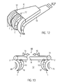
- Fig. 12 multiple manipulator tools 1 can be arranged side by side and operated independently or simultaneously with each other.
- the manipulator planes 12 may be parallel or intersect.
- the two cheeks 8, 10 can fan out in the manner of a finger, or the individual fingers can each be formed by a manipulator tool 1.
- the flexurally rigid cheek can have a high flexural rigidity or be rigidly formed in order to reduce or prevent deformation in this area and to limit the deformation essentially to the area of the fingers.
- the manipulator tool 1 can thus also be used as a gripping tool.
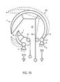
- Fig. 13 shows a further embodiment in which two manipulator tools 1 are arranged parallel to each other, wherein the proximal ends 2 arranged on a common tool base 4 and the at least rigid walls are associated with each other.
- Manipulator tools 1 lie in at least almost the same manipulator plane 12, in Fig. 13 the drawing plane.
- a spreading and / or gripping tool 66 which can be spread between two objects 68, 70 or in an opening of an object.
- a straight or mutually curved manipulator tools 1 are inserted between the objects 68, 70 and then the cheeks 10 driven longitudinally displaceable by acting on each cheek 10, a tensile force 16. Then the cheeks 8 curve in the direction of the objects 68, 70 and the holding and / or spreading tool wedges between the objects 68, 70th
- the two manipulator tools 1 can be arranged so as to be displaceable towards one another or away from one another along the tool base 4, so that the distance between the two manipulator tools 1 can be changed.
- the cheek 8 can be fastened to the tool base 4 via a hinge 72, so that when the pulling force 16 is applied, the cheek 8 initially moves substantially undeformed against the respectively associated object 68, 70 and only during further application of the pulling force during the movement Concerning the object 68, 70 curves.
- the cheek 10 or a pulling means connected to it can be deflected by a deflection roller 74.
- hinge 72 and the pulley 74 may also be used in any other embodiment described herein.
- FIGS. 14 and 15 show a further embodiment of a holding and / or Sp Dretzmaschinemaschinees, which is constructed of two manipulator tools 1, which are opposite to a gap 76, which serves for example to receive a workpiece.
- the at least tensile cheeks 10 face each other and define the gap 76.
- the gap 76 is open so that a workpiece (not shown) can be inserted from this side.
- the two cheeks 8 are fastened to the tool base 4 at the proximal end 2.
- the cheeks 10 are brought together at the proximal end 2 and end in a common traction means 78, so that they are actuated simultaneously in train.
- the course of the stiffness of the cheeks 8 in the direction from the proximal end 2 to the distal end 6 is selected such that a region 80 of reduced rigidity arises in the region of the proximal end of the intermediate space 76.
- This results in a train 16 ( Fig. 15 ) on the cheeks 10 the area 80 deforms more than the rest of the area of the cheek 8.
- the area 80 thus serves as an elastic joint around which distal ends 6 of the two manipulator tools 1 pivot.
- the region 80 of reduced stiffness can be done by a shaping, resulting in spikes in the material. Alternatively or additionally, this function can be achieved by reducing the wall thickness or by using a material of lower rigidity.
- the region 80 may be used instead of a hinge 72 when it comes to an elastic return function.
- the described holding and / or gripping function of the embodiment of Fig. 14 can be, as otherwise in the other embodiments also, in a simple manner in a spreading function, when the at least rigid cheeks 8 in the undeformed state, the in Fig. 14 occupy the position shown. Namely, the cheeks 8 are elastically deflected toward each other by the pulling force 16 and the width 82 of the holding and / or spreading tool decreases so that it can be inserted into an opening. If the tensile force is reduced, the cheeks 8 try again to spread elastically.
- the embodiment of the Fig. 16 differs from the embodiment of the FIGS. 14 and 15 by an articulated connection of the distal ends 6 of the two manipulator tools 1, so that an annularly closed interior 76 is formed.
- This embodiment is suitable in its basic form for spreading, but also for securely holding tubular objects.
- FIGS. 17 and 18 is a further example of a holding and / or spreading device 66 with two manipulator tools 1 shown. Also, this tool can be used depending on the initial curvature of the bending-resistant cheeks 8 either as a spreading and / or holding tool.
- the two cheeks 8 are in the embodiment of FIGS. 17 and 18 at a root 84, which may optionally be configured as a joint 72, connected to each other.
- the root 84 continues in a stem 86 which is connected to the tool base 4 at the proximal end 2.
- the two cheeks 8 run almost parallel to each other in the manipulator plane 12 and form between them the gap 76.
- the cheeks 8 move under magnification of the gap 76 away from each other.
- the holding and / or spreading tool in particular for example umbrella-like clamping or spreading of workpieces between the relative to the gap 76 opposite distal ends 6 of the two manipulator tools 1 suitable.
- Two manipulator tools 1 define a gap 76 with their cheeks 10 that are at least resistant to tension.
- the rigid cheeks 10 are connected by means of joints 72 to the tool base 4 at the proximal end 2 of the holding and / or spreading tool 66.
- the one manipulator tool 1 is significantly smaller than the other manipulator tool 1 and closes in the deformed state shown by solid lines the gap 76, while the larger manipulator tool 1 with its at least tensile cheek 10 sets out on the outside of the rigid cheek of the smaller tool.
- a holding and / or spreading tool 66 which may be made of sheet material by means of an injection molding, stamping or cutting process.
- Both cheeks 8, 10 of the two jaws 87 forming manipulator tools 1 are rigid, wherein the gap 76 facing cheeks 10 have a smaller wall thickness than the outer cheeks 8.
- the small wall thickness 8 also leads to greater flexibility of the cheeks 10, so that they are easier to place around gripping objects.
- the surface of the cheeks which performs the holding and / or spreading function can also be structured as required by the objects to be handled.
- the cheeks 10 a corrugation transverse to the longitudinal direction.
- the shear-movable connection via the at least one hinge element 20 is in the embodiment of the Fig. 20 achieved by the shaping in the region of the anchoring points 24, 30. Due to the almost rectangular connection of the elements 20 to the cheeks 8, 10 and in the region of the anchoring points 24, 30 slightly reduced wall thickness, the mobility is increased in the region of the anchoring points 24, 30, so that at these points a joint function is achieved.
- the outer cheeks 8 are connected via a hinge 72, which is produced by a weakening area in the form of an incision.
- the cheeks 8, 10 are joined together again to form an extension 48.
- the extension 48 allows a gentle gripping of objects.
- the cheeks 10 are integrally connected.
- a coupling element 88 for example in the form of an eyelet, may be provided.
- FIG. 20 shown tool 66 may at the end of a manipulator tool 1, as shown in the Fig. 1 to 6 is shown used.
- the tool base and the coupling 88 are interchanged or pressure forces are introduced at the coupling 88, then a spreading tool is created.
- Fig. 21 It is shown how, by the combination of two manipulator tools 1 according to the invention to form a holding and / or spreading tool 66, an article 68 can be adapted in a form-adaptive manner.
- the cheeks 10 engage the object 68 as a result of the pulling force 16 and adapt to its outer contour in the manipulator plane 12.
- the adaptation to the contour of the article 68 is also transferred to an extension 48, which is formed integrally with a reinforced at the distal end gripping region 90 on the inside of the cheeks 10.
- the shape adaptation can be connected to the outer cheek 8 and the rest of the cheek 10 by means of the hinged connection of the gripping area 90 via hinges 72 or areas 80 reduced flexural rigidity.
- Fig. 22 Fig. 4 shows how gripping area 90 can conform to the contour of another article 68 due to the hinged connection.
- FIG. 23 and 24 An embodiment of the holding and / or spreading tool 66, which is particularly suitable for endoscopic applications is in the Fig. 23 and 24 shown schematically.
- the holding and / or spreading tool is closed, in the Fig. 24 shown in a gripping position without gripped object.
- the holding and / or spreading tool 66 has three or more manipulator tools 1, which surround an inner space 76 in a star shape and which are mounted within a substantially circular outer contour.
- the holding and / or spreading tool 66 for example, in conjunction with endoscopes and push through them.
- the at least rigid cheeks 8 are fixedly clamped to the tool base 4.
- the clamping takes place here via elastically prestressed joints, which generate a cheeks 8 away from each other moving spring force.
- the at least tensile cheeks 10 face the gap 76.
- a tensile force 16 can be applied to the at least tensile cheeks 10.
- a pulling force 16 causes the manipulator tools 1 to be moved toward one another in an essentially undeformed manner against the spring force of the elastically prestressed joints and to prevent them from moving inwards Fig. 23 take shown position and can also be completely closed bud-shaped. However, this assumes that the stiffness in the joint is lower than the stiffness of the rigid cheeks. In the closed position, the embodiment of the Fig. 23 and 24 a slim cross-sectional shape, so that the gripping tool can be used especially in confined space situations, for example, as a fruit picker between branches or at the end of an endoscope between organs can be passed.
- the manipulator tools 1 are initially pivoted inwardly undeformed until they bear against the object when a tensile force is applied. Only the further longitudinal movement of the at least tensile cheeks 10 causes the in Fig. 2 shown deformation of Manipulatorwerkzeue endeavor. Biege stiff cheeks 8, which create the outer contour of the object.
- the manipulator tool 1 have a starting position in which it presses against the jaw 94.
- the outer cheek 10 By pulling on the outer cheek 10 it takes the in Fig. 25 shown position in which it is moved away from the opposite jaw 94, so that an object can be inserted into the gap 76.
- the design of the jaw 94 can be done depending on the desired function. With a suitable gripping function, the jaw 94 a contact surface for a in the space 76th train the object to be held. However, the jaw 94 may also be configured as a blade to cut through the article disposed in the gap 76 subject to a drop in tensile force 16. This is particularly useful in the field of vascular surgery when the in Fig. 25 shown holding and / or spreading tool is used for example in endoscopes.
- the embodiment of the Fig. 25 can be used in accordance with ergonomic design of the jaw 94 and the manipulator tool 1 as a handle that allows 16 to use other tools, not shown on the force.
- Fig. 26 shows a manipulator tool 1, which is used as an endoscope and threaded through between articles 68.
- the basic structure of such an endoscope can the structure of the embodiment of the FIGS. 5 and 6 correspond, in which the two cheeks 8, 10 are rigid and absorb both tensile and compressive forces, or one cheek 8 only compressive forces and the other cheek 10 only absorbs tensile forces.
- the distal end 6 of the manipulator tool 1 is free, by applying the forces 16, 18, the tip can be moved and placed around the objects 68 around. In this way, the distal end 6 can always be aligned so that it has between two adjacent objects 68, and the manipulator tool 1 can be interposed.
- a tool or an observation device attached to the distal end 6 may be repositioned about a last object 68, or this last object may be grasped, as indicated by the dashed line in FIG Fig. 26 is indicated.
- the hinge elements 20 are in Fig. 26 omitted for clarity.
- a central, rigid cheek 8 is divided by at least two cheeks 10 at least ten.
- the central bending-resistant cheek 8 is preferably held pivotably on the tool base 4.
- Each individual cheek 10 can be driven longitudinally displaceably at its proximal end 2.
- a curvature of the rigid cheek 8 can be achieved in the particular desired direction.
- the cheeks 10 may be arranged in more than one manipulator plane 12 and thus cause a three-dimensional curvature of the central cheek 8. Again, this is beneficial for endoscopic use.
- each opposing pairs of driven cheeks 10 are provided, the at least rigid cheek 8 must not be configured as a spring element, since the provision can be made by train on the opposite cheek 10.
- FIG. 28 to 30 Another embodiment, which allows a three-dimensional curvature of the manipulator tool 1 is in the Fig. 28 to 30 shown.
- a base area 96 of the tool base 4 in a circumferential direction 98 at least three, but preferably four cheeks 8, 10 are provided, which are connected in the circumferential direction, ie transversely to its longitudinal extent, by hinge elements 20.
- the cheeks 8, 10 are connected to a flexible sheath 102 which defines the structure to the outside and the cheeks 8, 10, the hinge elements 20 and the spacers 100 receives.
- This embodiment does not require that all cheeks 8, 10 are rigid.
- the number of bending walls which are at least necessary depends on the number of cheeks present in total in the manipulator tool 1 and on the number of bending-resistant cheeks necessary for shaping and rigidity.
- sheath 102 is of sufficient rigidity to support the cheeks 8, 10, they may also be segmented, i. H. be articulated by joints 104.
- the spacers 100 may extend anywhere between the cheeks, hinge members or hinges and the sheath 102.
- the hinge elements 20 may be substantially parallel to the envelope.
- the rigid cheek 8 is hollow and flexible, so that it can be inflated by a fluid 106 in its interior.
- the cheek 8 is limp when the fluid 106 is not under pressure, or is emptied.
- the manipulator tool 1 can thus be pushed through very small openings and then inflated.
- Embodiments 1 of the FIGS. 33 to 35 On the one hand, different embodiments of the connection of the at least rigid cheek 8 to the tool base 4 in the form of joints 72 in areas of reduced rigidity 80 are shown.
- the tool base 4 may have a knee 108, which serves as a guide for the loadable by a tensile force 16, at least tenable cheek 10.
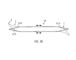
- Fig. 36 shows an embodiment in which at the ends of an elongated tool 110, two manipulator tools 1 are arranged, the cheeks 8, 10 are connected to each other, so that they are always operated simultaneously and in opposite directions.
- Fig. 37 shows an example of a section through such an embodiment.
- the tool base 4 is formed by an example polygonal base body, at the two opposite ends of the manipulator tools 1 are arranged.
- the area 112 between the two manipulator tools can be designed as a handle. If the tool base 4 is impressed with a shearing motion as a working movement, a tensile force or longitudinal movement is simultaneously introduced into one cheek of the one manipulator tool and a compressive force or longitudinal movement in the same direction into the cheek of the other manipulator tool on one side of the tool base. On the other side, there is a reverse direction of force. This results in a deformation of the manipulator tools 1 in the in Fig. 37 dashed form shown.
- Fig. 38 shows a handle 114 for the simultaneous generation of a compressive force 18 and a tensile force 16 in a manipulator tool 1, not shown, which is connected to the tension / pressure means 116.
- the handle 14 is articulated and can, as indicated by the arrow 118, be tilted.
- a compressive force is generated, the pulling force 16 being directed away from the tilting direction.
- the bearing of the handle 108 is preferably carried out at a location which is rigidly connected to the tool base 4.
- Fig. 39 shows the embodiment of a manipulator tool 1 in tube form.
- the interior 120 at least freely opens at the proximal end 2 and thus suitable for receiving other instruments or for the passage of fluids, adjacent cheeks 8, 10 are not wedge-shaped at its distal end 6, but bluntly connected by a respective end member 122.
- the use of such a closure element 122 is irrelevant to the effect according to the invention, as long as in the case of the wedge-shaped connection point 14 (FIG. Fig. 1 ) ensures that the angles between the adjacent cheeks 8, 10, which are connected to each other at this point, not or only insignificantly change in the deformation.
- the movable cheeks of a development at the proximal end can be connected by a rigid ring, on the movement of which in particular tilting the deformation of the tube is effected by the attached cheeks are moved simultaneously.
- the tube can be used as a separate instrument, for example as a movable tube.
- the shape of the hinge elements 20 is as long as they have their with respect to the Fig. 2 fulfill described function, determined primarily by the application of the manipulator tool 1.
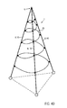
- a continuous hinge element extending helically between a plurality of cheeks 8, 10, such as Fig. 40 shows.
- circles as in Fig. 39 or other geometric configurations are used.
- the at least rigid cheek 8 itself can be hollow and serve as a tool holder for therein longitudinally displaceable recorded tools. This is in the FIGS. 41 to 43 shown.
- tools such as a blade 124, a needle 126 or a loop 128 may be received in the rigid cheek 8.
- fluids can be passed or electrical or optical devices recorded.
- Fig. 44 shows that at the distal end 6, the connection between the cheeks 8, 10 need not be wedge-shaped, but also blunt by the closing element 122, which may be formed, for example, integral with the at least rigid cheek 10 takes place. All that is essential is that at the distal end 6 there is a triangular figure that is essentially angularly stable over the deformation of the manipulator tool 1, which in FIG Fig. 44 indicated by the dot-dash line.
Abstract
Description
Die Erfindung betrifft ein biegsames Manipulatorwerkzeug mit einem gegenüber einem proximalen Ende in wenigstens einer Manipulationsebene beweglichen distalen Ende, mit wenigstens zwei nebeneinander beabstandet verlaufenden, wenigstens in der Manipulationsebene flexiblen und sich vom proximalen Ende zum distalen Ende erstreckenden Wangen, die zwischen dem proximalen Ende und dem distalen Ende durch wenigstens ein wenigstens zugfestes Scharnierelement gegeneinander scherbeweglich verbunden und am proximalen Ende voneinander beabstandet gehalten sind, wobei die eine Wange wenigstens biegesteif und die andere Wange wenigstens zugfest ausgestaltet und die wenigstens zugfeste Wange an ihrem distalen Ende mit der wenigstens biegesteifen Wange Zugkraft übertragend verbunden ist.The invention relates to a flexible manipulator tool having a distal end which is movable relative to a proximal end in at least one manipulation plane and having at least two cheeks which extend next to one another and are flexible at least in the manipulation plane and which extend from the proximal end to the distal end between the proximal end and the distal end by at least one at least tensile hinge element against each other shearly connected and held spaced from each other at the proximal end, one cheek at least rigid and the other cheek configured at least tensile strength and connected the at least tensile cheek at its distal end with the at least rigid cheek traction transmitting is.
Eine Vorrichtung mit diesen Merkmalen ist beispielsweise aus der
Das wenigstens eine Scharnierelement und die wenigstens eine Wange sind wenigstens zugfest, können also zumindest Zugkräfte übertragen. In der einfachsten Form können daher als Scharnierelemente und als eine Wange biegeschlaffe Zugmittel wie Seile, Bänder oder Riemen verwendet werden. Mit dem Ausdruck "wenigstens zugfest" soll zum Ausdruck gebracht werden, dass diese Elemente über die reine Zugfestigkeit hinaus als Mindestanforderung biegesteif sein können, also auch Druckkräfte übertragen können.The at least one hinge element and the at least one cheek are at least tensile, so can transmit at least tensile forces. In the simplest form can therefore be used as hinge elements and as a cheek pliable pulling means such as ropes, belts or belts. The expression "at least tensile strength" is intended to express that these elements can be resistant to bending beyond the mere tensile strength as a minimum requirement, that is, they can also transmit compressive forces.
Die biegesteife Wange ist flexibel, aber nicht biegeschlaff, vorzugsweise elastisch und kann Druckkraft aufnehmen. Sie kann zusätzlich zugfest ausgestaltet sein.The rigid cheek is flexible, but not limp, preferably elastic and can absorb compressive force. You can also be configured tensile strength.
Das wenigstens eine Scharnierelement ist so mit den beiden Wangen verbunden, dass beide Wangen eine Scherbewegung relativ zueinander ausführen, sich also in ihrer Längsrichtung relativ zueinander verschieben können. Durch die zugfeste Ausgestaltung des Scharnierelements ist dabei sichergestellt, dass die beiden Verankerungspunkte des Scharnierelements in den Wangen stets den gleichen Abstand voneinander haben, also der eine Verankerungspunkt einen Kreis um den anderen Verankerungspunkt im Zuge der Scherbewegung beschreibt. Aufgrund der zugfesten Verbindung am distalen Ende führt die Scherbewegung zu einer Krümmung der Wangen. Ausdrücklich soll eine kontrollierte Elastizität des Scharnierelements in dessen Längsrichtung gestattet sein.The at least one hinge element is connected to the two cheeks in such a way that both cheeks execute a shearing motion relative to one another, that is, they can shift relative to one another in their longitudinal direction. Due to the tensile design of the hinge element is thereby ensured that the two anchoring points of the hinge element in the cheeks always have the same distance from each other, so one anchoring point describes a circle around the other anchoring point in the course of the shearing motion. Due to the tensile strength at the distal end of the shear movement leads to a curvature of the cheeks. Specifically, a controlled elasticity of the hinge element in the longitudinal direction should be allowed.
Die andere Wange ist wenigstens biegesteif, überträgt also wenigstens Druckkräfte. Lediglich in einer Weiterbildung kann sie auch zusätzlich zugfest sein.The other cheek is at least rigid, so transmits at least compressive forces. Only in a further development, it can also be tensile strength.
Die Vorrichtung mit den beiden am proximalen Ende festgelegten Wangen nach den obigen Druckschriften kann nach der Lehre der
Die Einsatzmöglichkeiten der oben beschriebenen, bekannten Vorrichtungen sind begrenzt. Die Erfindung setzt sich daher zum Ziel, den bekannten Grundaufbau so abzuändern, dass die Einsatzmöglichkeiten vergrößert werden.The applications of the above-described, known devices are limited. The invention is therefore based on the goal of modifying the known basic structure so that the possible applications are increased.
Diese Aufgabe wird erfindungsgemäß für das eingangs genannte Manipulatorwerkzeug dadurch gelöst, dass wenigstens eine Wange am proximalen Ende in Richtung des distalen Endes längsbeweglich antreibbar ausgestaltet ist.This object is achieved according to the invention for the above-mentioned manipulator tool in that at least one cheek at the proximal end in the direction of the distal end is longitudinally movably driven.
Durch diese einfache Lösung ist das Einsatzgebiet des biegsamen Manipulatorwerkzeugs gegenüber den vorbekannten Vorrichtungen deutlich erweitert, weil die lineare Antriebsbewegung direkt durch mit der Wange verbundene Zugmittel oder Druckstangen erfolgen kann. Dies führt zu einem geringeren Platzbedarf, so dass sich das erfindungsgemäße Manipulatorwerkzeug insbesondere für kompakte und dünne, langgestreckte Werkzeuge eignet. Die Längsbewegung der antreibbaren Wange führt zu einer kontrollierten und steuerbaren Verformung des Manipulatorwerkzeuges.By this simple solution, the field of application of the flexible manipulator tool over the prior art devices is significantly expanded because the linear drive movement can be done directly by connected to the cheek traction means or push rods. This leads to a smaller space requirement, so that the manipulator tool according to the invention is particularly suitable for compact and thin, elongated tools. The longitudinal movement of the driven cheek leads to a controlled and controllable deformation of the manipulator tool.
Der längsbewegliche Antrieb wenigstens einer Wange am proximalen Ende ist zum Antrieb eines Unterwasserfahrzeugs, wie es in der
Die erfindungsgemäße Lösung kann durch zusätzliche, beliebig miteinander kombinierbare Merkmale weiter verbessert werden, wie nachstehend beschrieben ist.The solution according to the invention can be further improved by additional features which can be combined with one another as desired, as described below.
So kann in einer vorteilhaften Ausgestaltung die längsbeweglich antreibbare Wange sowohl zugfest als auch biegesteif ausgebildet sein, so dass als Antriebskräfte sowohl Zug- als auch Druckkräfte auf die Wange einwirken können. In dieser Ausgestaltung ist die längsverschiebliche Wange vorzugsweise hin und her beweglich antreibbar am proximalen Ende gehalten.Thus, in an advantageous embodiment, the longitudinally moveable cheek can be designed both tensile strength and bending stiff, so that both tensile and compressive forces can act as driving forces on the cheek. In this embodiment, the longitudinally displaceable cheek is preferably held reciprocably movable at the proximal end.
Wird das erfindungsgemäße Manipulatorwerkzeug als Werkzeugträger verwendet, so kann am distalen Ende oder an wenigstens einer Wange eine Werkzeughalter angeordnet sein. Bei dieser Ausgestaltung dient das Manipulatorwerkzeug dazu, dass in der Werkzeughalter angeordnete Werkzeug zu bewegen.If the manipulator tool according to the invention is used as a tool carrier, then a tool holder can be arranged on the distal end or on at least one cheek. In this embodiment, the manipulator tool is used to move that arranged in the tool holder tool.
Um bei einer Verwendung als Werkzeughalter wenigstens ein Werkzeug im Inneren des Manipulatorwerkzeuges aufzunehmen, kann beispielsweise eine Wange hohl und/oder der Zwischenraum zwischen den Wangen als Aufnahme ausgestaltet sein. Zu diesem Zweck können die Scharnierelemente ringförmig, hohl und/oder gekrümmt sein.In order to accommodate at least one tool in the interior of the manipulator tool when used as a tool holder, for example, a cheek hollow and / or the space between the cheeks can be configured as a receptacle. For this purpose, the hinge elements may be annular, hollow and / or curved.
Das Manipulatorwerkzeug kann an seinem proximalen Ende an einer Werkzeugbasis gelenkig gelagert oder fest eingespannt sein, wobei die Befestigung über wenigstens eine Wange oder ein Scharnierelement erfolgen kann. Dabei kann die als Befestigung dienende Wange an der Werkzeugbasis. Bei einer gelenkigen Lagerung oder einer hohen Flexibilität im an der Werkzeugbasis angrenzenden Bereich des Manipulatorwerkzeuges kann das gesamte Manipulatorwerkzeug durch den Antrieb der längsbeweglichen Wange verschwenkt werden, bis eine Wange an einen Gegenstand fährt. Erst dann setzt bei weiterem Antrieb der längsbeweglichen Wange eine Verformung aufgrund des vom Gegenstand ausgeübten Widerstandes ein.The manipulator tool can be articulated or firmly clamped at its proximal end on a tool base, wherein the attachment can take place via at least one cheek or a hinge element. It can serve as a mounting cheek on the tool base. In an articulated storage or a high flexibility in the area adjacent to the tool base area of the manipulator tool, the entire manipulator tool can be pivoted by the drive of the longitudinally movable cheek until a cheek is moving to an object. Only then does further deformation of the longitudinally movable cheek result in deformation due to the resistance exerted by the object.
Alternativ können auch beide, oder mehr als zwei Wangen am proximalen Ende längsbeweglich gehalten sein, so dass sich die durch die Antriebsbewegung hervorgerufene Verformung des Manipulatorwerkzeugs in Abhängigkeit von der Relativbewegung der beiden Wangen am proximalen Ende ergibt. Eine kontrollierte Verformung des Manipulatorwerkzeuges lässt sich erreichen, wenn wenigstens eine Wange eine in Richtung vom proximalen zum distalen Ende sich verändernde Steifigkeit aufweist. An Stellen erhöhter Steifigkeit wird sich das Manipulatorwerkzeug durch die Antriebsbewegung weniger stark krümmen als an Stellen verringerter Steifigkeit.Alternatively, both, or more than two cheeks may be held longitudinally movable at the proximal end, so that the deformation of the manipulator tool caused by the drive movement results in dependence on the relative movement of the two cheeks at the proximal end. A controlled deformation of the manipulator tool can be achieved if at least one cheek has a stiffness varying in the direction from the proximal to the distal end. At points of increased stiffness, the manipulator tool will bend less strongly by the drive motion than at points of reduced stiffness.
Die eine Wange, vorzugsweise die wenigstens biegesteife Wange, kann über die Verbindungsstelle mit der anderen Wange hinaus verlängert sein. Die Verlängerung kann insbesondere platten- oder scheibenförmig ausgestaltet sein, was insbesondere als Träger für Wisch-, Schab- und/oder Kratzorgane sinnvoll ist.One cheek, preferably the at least rigid cheek, may be extended beyond the junction with the other cheek. The extension may be designed in particular plate or disc-shaped, which is useful in particular as a carrier for wiping, scraping and / or scraping organs.
An das distale Ende kann sich auch erfindungsgemäßes Manipulatorwerkzeug und/oder eine Vorrichtung, wie sie aus der
In einer weiteren vorteilhaften Ausgestaltung kann die wenigstens biegesteife Wange als Federelement ausgestaltet sein, dessen Federkraft in die wenigstens zugfeste Wange eingeleitet ist. Das Federelement dient bei dieser Ausgestaltung als Rückstellorgan, welches eine durch die Längsbewegung der antreibbaren Wange erzeugte Formänderung des Manipulatorwerkzeuges automatisch in eine Ausgangsstellung zurückführt. Die Federwirkung ist der Antriebswirkung entgegengesetzt.In a further advantageous embodiment, the at least rigid cheek be configured as a spring element whose spring force is introduced into the at least tensile cheek. The spring element is used in this embodiment as a return member which automatically returns a generated by the longitudinal movement of the driven cheek shape change of the manipulator tool in a starting position. The spring effect is opposite to the drive effect.
Die Form der Wangen ist, solange der eingangs genannte Grundaufbau eingehalten ist, an den einzelnen Anwendungsfall anpassbar. So kann jede Wange klappen- oder scheibenförmig, gabelartig geteilt oder in Fingern auslaufend ausgestaltet sein. Ferner können die Wangen eine beliebige vorbestimme Krümmung aufweisen.The shape of the cheeks, as long as the above-mentioned basic structure is met, adaptable to the individual application. Thus, each cheek can be flapped or disc-shaped, fork-shaped or designed to run out in fingers. Further, the cheeks may have any predetermined curvature.
Das wenigstens eine Scharnierelement kann ebenfalls eine beliebige Raumform aufweisen.The at least one hinge element can likewise have any desired spatial form.
Eine besonders vorteilhafte Ausgestaltung ergibt sich, wenn wenigstens ein Manipulatorwerkzeug als eine Backe eines Halte- und/oder Spreizwerkzeuges eingesetzt wird, wobei das Halte- und/oder Spreizwerkzeug wenigstens zwei bezüglich eines Zwischenraumes einander gegenüberliegende Backen, von denen wenigstens eine Backe bezüglich der anderen Backe beweglich ist, aufweist. Vorzugsweise bildet das Manipulatorwerkzeug wenigstens eine bewegliche Backe des Halte- und/oder Spreizwerkzeuges.A particularly advantageous embodiment is obtained if at least one manipulator tool is used as a jaw of a holding and / or spreading tool, wherein the holding and / or spreading at least two with respect to a gap opposing jaws, of which at least one jaw with respect to the other jaw is mobile, has. Preferably, the manipulator tool forms at least one movable jaw of the holding and / or spreading tool.
Das Halte- und/oder Spreizwerkzeug dient zum Halten, Greifen, Kneifen und/oder Klemmen etc. eines im Zwischenraum angeordneten Gegenstandes und in einer kinematischen Umkehr der Halte- oder Greiffunktion auch dazu, unter Vergrößerung des Zwischenraumes eine Spreizkraft auf zwei sich im Wesentlichen gegenüberliegende Wandabschnitte einer Öffnung oder eines Spaltes oder auf zwei voneinander beabstandete Gegenstände auszuüben. Bei der Halte- und Greiffunktion stellt die Arbeitsbewegung die Relativbewegung der beiden Backen aufeinander zu unter Verkleinerung des Zwischenraumes dar. Bei der Spreizfunktion bildet die Relativbewegung der beiden Backen voneinander weg die Arbeitsbewegung. In ihrem Grundaufbau müssen sich folglich ein erfindungsgemäßes Haltewerkzeug und ein erfindungsgemäßes Spreizwerkzeug zunächst nicht unterscheiden. Sollte jedoch die Haltefunktion in Einzelfällen gegenüber der Spreizfunktion die Abwandlung von Merkmalen erfordern, ist dies im Folgenden angegeben.The holding and / or spreading tool is used for holding, gripping, pinching and / or clamping etc. of an object arranged in the intermediate space and in a kinematic reversal the holding or gripping function also to exert an expansion force on two substantially opposite wall portions of an opening or a gap or on two spaced-apart objects under enlargement of the intermediate space. In the holding and gripping function, the working movement represents the relative movement of the two jaws toward each other under reduction of the gap. In the spreading function, the relative movement of the two jaws away from each other forms the working movement. Consequently, in its basic structure, a holding tool according to the invention and a spreading tool according to the invention need not initially differ. If, however, the holding function requires the modification of features in individual cases compared to the spreading function, this is indicated below.
Ein beispielsweise in Längsrichtung des Manipulatorwerkzeuges ringförmig geschlossener Zwischenraum ergibt sich, wenn das Manipulatorwerkzeug an seinem distalen Ende mit dem distalen Ende der anderen Backe gelenkig verbunden ist.An annular space closed annularly, for example in the longitudinal direction of the manipulator tool, results when the manipulator tool is articulated at its distal end to the distal end of the other jaw.
Das Halte- und/oder Spreizwerkzeug kann insbesondere wenigstens ein Paar von sich bezüglich des Zwischenraumes gegenüberliegenden Manipulatorwerkzeugen in einer der obigen Ausgestaltungen als Backen aufweisen.The holding and / or spreading tool may in particular have at least one pair of manipulator tools opposite one another with respect to the intermediate space in one of the above embodiments as jaws.
Das Manipulatorwerkzeug wie auch das Halte- und/oder Spreizwerkzeug kann aus einem integralen Körper geformt sein, beispielsweise durch ein Spritzguss-, Stanz- oder Schneideverfahren.The manipulator tool as well as the holding and / or spreading tool can be formed from an integral body, for example by an injection molding, stamping or cutting process.
Zwei Manipulatorwerkzeuge können zur Bildung eines Halte- und/oder Spreizwerkzeuges an ihrem proximalen Ende einstückig miteinander verbundene antreibbare Wangen aufweisen. Bei dieser Ausführung erfolgt der Antrieb der beiden Manipulatorwerkzeuge gemeinsam und gleichzeitig. Die Antriebskraft kann in einer Weiterbildung dieser Ausführung durch ein zwischengeschaltetes Gelenk an die beiden gemeinsam antreibbaren Wangen geleitet sein, um Querkräfte zu vermeiden.Two manipulator tools can have integrally connected drivable cheeks at their proximal end to form a holding and / or spreading tool. In this embodiment, the drive of the two manipulator tools takes place together and simultaneously. The driving force can be passed in an embodiment of this embodiment by an intermediate joint to the two jointly driven cheeks to avoid lateral forces.
Eine handähnliche Ausgestaltung des Halte- und/oder Spreizwerkzeugs lässt sich erreichen, wenn an zumindest einer Seite des Zwischenraums eine Mehrzahl von Manipulatorwerkzeugen angeordnet ist. Das Manipulatorwerkzeug einer Seite übernimmt dabei die Funktion eines Fingers.A hand-like embodiment of the holding and / or spreading tool can be achieved if a plurality of manipulator tools is arranged on at least one side of the intermediate space. The manipulator tool of a page assumes the function of a finger.
Die erfindungsgemäßen Manipulatorwerkzeuge können nicht nur, wie bei dem Halte- und/oder Spreizwerkzeug parallel zueinander, sondern auch in Reihe geschaltet sein. Hierzu kann wenigstens ein weiteres Manipulatorwerkzeug an wenigstens einer Wange eines anderen Manipulatorwerkzeuges befestigt sein. Das weitere Manipulatorwerkzeug kann am distalen Ende eines vorangehenden Manipulatorwerkzeuges angebracht sein. Alternativ oder zusätzlich können sich mehrere Manipulatorwerkzeuge auch eine gemeinsame, durchgehende Wange teilen. Die längsbeweglich antreibbare Wange kann sowohl zugfest als auch biegesteif ausgebildet sein, so dass eine Antriebsbewegung in beiden Richtungen unter Einleitung sowohl einer Zug- als auch einer Druckkraft möglich ist.The manipulator tools according to the invention can not only, as in the holding and / or spreading tool parallel to each other, but also be connected in series. For this purpose, at least one further manipulator tool can be attached to at least one cheek of another manipulator tool. The further manipulator tool can be attached to the distal end of a preceding manipulator tool. Alternatively or additionally, a plurality of manipulator tools can also share a common, continuous cheek. The longitudinally movable drivable cheek can be formed both tensile and bending stiff, so that a drive movement in both directions by initiating both a tensile and a compressive force is possible.
Am distalen Ende kann die eine Wange über die andere Wange hinaus unter Bildung eines Fortsatzes verlängert sein. Der Fortsatz kann als Werkzeughalter dienen oder selbst eine Werkzeugfunktion wahrnehmen. Vorzugsweise ist der Fortsatz von der wenigstens biegesteifen Wange gebildet. Die Form und Elastizität des Fortsatzes sowie sein Material können je nach Anwendungsfall variieren.At the distal end, one cheek may extend beyond the other cheek to form an appendage. The extension can serve as a tool holder or even perform a tool function. Preferably, the extension of the at least rigid cheek is formed. The shape and elasticity of the extension and its material may vary depending on the application.
Das erfindungsgemäße Manipulatorwerkzeug eignet sich insbesondere als endoskopisches Instrument in technischen oder medizinischen, insbesondere minimalinvasiven Anwendungen. Hierzu kann es innerhalb einer flexiblen Hülle angeordnet sein. Das erfindungsgemäße Halte- und/oder Spreizwerkzeug ist aufgrund des geringen Platzbedarfs ebenfalls insbesondere für endoskopische Anwendungen geeignet und kann insbesondere an der Spitze eines Endoskops eingesetzt werden. Die Antriebsmittel für die wenigstens eine längsverschiebliche Wange können durch das Endoskop geführt sein, was insbesondere bei der Verwendung von biegeschlaffen Zugmitteln als Antriebsmittel ohne großen Konstruktionsaufwand und ohne Beeinträchtigung der Beweglichkeit des Endoskops möglich ist.The manipulator tool according to the invention is particularly suitable as an endoscopic instrument in technical or medical, in particular minimally invasive applications. For this purpose it can be arranged within a flexible envelope. The holding and / or spreading tool according to the invention is also particularly suitable for endoscopic applications due to the small footprint and can be used in particular at the tip of an endoscope. The drive means for the at least one longitudinally displaceable cheek can be guided by the endoscope, which is possible in particular when using fast-moving traction means as a drive means without great design effort and without affecting the mobility of the endoscope.
Um die Flexibilität zu erhöhen, können gemäß einer vorteilhaften Ausgestaltung wenigstens drei Wangen vorgesehen sein, von denen wenigstens zwei längsbeweglich angetrieben sind. Die Wangen können unterschiedlich oder gleich lang und/oder miteinander verbunden sein.In order to increase the flexibility, according to an advantageous embodiment, at least three cheeks may be provided, of which at least two are driven longitudinally movable. The cheeks may be different or equal in length and / or interconnected.
Liegen gemäß einer Ausgestaltung wenigstens drei Wangen in einer gemeinsamen Manipulatorebene, so lässt sich eine ebene Verformung erzielen. Wirken die Antriebsbewegungen der wenigstens zwei längsbeweglich angetriebenen Wangen gegeneinander, so kann auf eine federnde Ausgestaltung der biegefesten Wange verzichtet werden.If, according to one embodiment, at least three cheeks lie in a common manipulator plane, a planar deformation can be achieved. Act the driving movements of the at least two longitudinally driven cheeks against each other, it can be dispensed with a resilient design of the bending resistant cheek.
Um eine kontrollierte räumliche Verformung zu erreichen, können die wenigstens drei Wangen in unterschiedlichen Manipulatorebenen liegen. Die Manipulatorebenen können sich insbesondere in einer gemeinsamen Achse schneiden, wobei diese Achse bevorzugt in Längsrichtung des Manipulatorwerkzeuges weist. So lassen sich beispielsweise bei drei um 120 Grad versetzten Wangen beliebige Krümmungen in jede Raumrichtung erzeugen.In order to achieve a controlled spatial deformation, the at least three cheeks can lie in different manipulator planes. The manipulator planes can intersect in particular in a common axis, wherein this axis preferably points in the longitudinal direction of the manipulator tool. For example, with three cheeks offset by 120 degrees, any curvature can be created in any direction.
Jeweils benachbarte Wangen können durch Scharnierelemente verbunden sein, so dass eine kombinierte Struktur mit komplexer Verformungsgeometrie entsteht.Each adjacent cheeks can be connected by hinge elements, so that a combined structure with complex deformation geometry arises.
Mehrere Wangen können aber auch um einen Innenraum herum angeordnet sein, so dass ein schlauchförmiges Gebilde entsteht., wobei die Scharnierelemente in Umfangsrichtung und die Wangen in Längsrichtung den Schlauch aufspannen können. Der Innenraum kann in distaler Richtung offen sein, so dass Fluide und/oder Werkzeuge am distalen Ende appliziert werden können. Wenn der Innenraum auch am proximalen Ende geöffnet ist, können durch den Innenraum Fluide hindurchgeleitet werden. Hierzu ist das Manipulatorwerkzeug vorzugsweise mit einer fluiddichten, schlauchförmigen Hülle umgeben.However, a plurality of cheeks can also be arranged around an inner space, so that a tubular structure is formed, wherein the hinge elements in the circumferential direction and the cheeks in the longitudinal direction can span the hose. The interior can be open in the distal direction, so that fluids and / or tools can be applied at the distal end. If the interior is also open at the proximal end, fluids can be passed through the interior. For this purpose, the manipulator tool is preferably surrounded by a fluid-tight, tubular casing.
Einzelne Wangen des Schlauches können am proximalen Ende unabhängig voneinander längsbeweglich angetrieben sein. Die längsbeweglichen Wangen können auch mit einem steifen Ring am proximalen Ende miteinander verbunden sein, so dass sich die Bewegung des Ringes, insbesondere sein Verkippen, in eine Antriebsbewegung aller damit verbundenen Wangen umsetzt und eine Verformung des Schlauches bewirkt. Auf diese Weise erhält man ein eigenständiges schlauchförmiges, aktiv steuerbares Instrument, das beispielsweise als Tubus in der Medizintechnik einsetzbar ist.Individual cheeks of the tube can be independently driven longitudinally movable at the proximal end. The longitudinally movable cheeks can also be connected to each other with a rigid ring at the proximal end, so that the movement of the ring, in particular its tilting, converts into a drive movement of all cheeks connected thereto and causes a deformation of the tube. In this way, one obtains an independent, tubular, actively controllable instrument which can be used, for example, as a tube in medical technology.
Jeweils eine wenigstens biegesteife Wange kann mit jeweils wenigstens zwei wenigstens zugfesten, längsbeweglichen Wangen am distalen Ende verbunden sein, die in einer Manipulatorebene an jeweils einer Seite der wenigstens biegesteifen Wange liegen und somit einander entgegenwirken.In each case, an at least rigid cheek can be connected to at least two at least tensile, longitudinally movable cheeks at the distal end, which lie in a manipulator plane on each side of the at least rigid cheek and thus counteract each other.
Die wenigstens biegesteife Wange kann auch hohl sein, so dass sie selber einen Schlauch bildet oder einen Schaft für die Aufnahme von Instrumenten.The at least rigid cheek may also be hollow, so that it forms a tube itself or a shaft for receiving instruments.
Schließlich muss die Verbindung der Wangen am distalen Ende nicht keilförmig verlaufen. Wesentlich ist lediglich, dass sich im Zuge der Verformung am distalen Ende der Verbindungswinkel zwischen den beiden Enden nicht ändert, die Verbindung also im Wesentlichen winkelstarr ist.Finally, the connection of the cheeks at the distal end does not have to be wedge-shaped. It is only essential that in the course of deformation at the distal end of the connection angle between the two ends does not change, so the connection is essentially fixed angle.
Im Folgenden wird die Erfindung anhand von Ausführungsformen beispielhaft näher erläutert. Bei den einzelnen Ausführungsformen unterschiedliche Merkmale können dabei Maßgabe der obigen Ausführungen beliebig miteinander kombiniert werden, falls es bei speziellen Anwendung auf den mit dem Merkmal verbundenen Vorteil besonders ankommt.In the following, the invention will be explained in more detail by way of example with reference to embodiments. In the individual embodiments, different features can be combined arbitrarily with one another in accordance with the above statements, if, in the case of a specific application, it is particularly important for the advantage associated with the feature.
Es zeigen:
- Fig. 1
- eine schematische Darstellung einer ersten Ausführungsform des erfindungsge- mäßen Manipulatorwerkzeuges in einer Ausgangsstellung;
- Fig. 2
- eine schematische Darstellung der Ausführungsform der
Fig. 1 in einer verformten Stellung; - Fig. 3
- eine weitere Ausführungsform des erfindungsgemäßen Manipulatorwerkzeuges in einer Ausgangsstellung;
- Fig. 4
- die Ausführungsform der
Fig. 3 in einer schematischen Darstellung einer verform- ten Stellung; - Fig. 5
- eine schematische Darstellung einer weiteren Ausführungsform des erfindungsge- mäßen Manipulatorwerkzeuges in einer Ausgangsstellung;
- Fig. 6
- die Ausführungsform der
Fig. 5 in einer schematischen Darstellung einer verform- ten Stellung; - Fig. 7
bis 10 - schematische Darstellung von verschiedenen Ausführungsformen eines dista- len Endes des erfindungsgemäßen Manipulatorwerkzeuges;
- Fig. 11
- eine schematische Darstellung einer Ausführungsform eines Scharnierelements des erfindungsgemäßen Manipulatorwerkzeuges;
- Fig. 12
- eine schematische Darstellung einer weiteren Ausführungsform des erfindungsge- mäßen Manipulatorwerkzeuges;
- Fig. 13
- eine schematische Darstellung einer Ausführungsform eines erfindungsgemäßen Halte- und/oder Spreizwerkzeuges;
- Fig. 14
- eine schematische Darstellung einer weiteren Ausführungsform eines erfindungs- gemäßen Halte- und/oder Spreizwerkzeuges in einer Ausgangsstellung;
- Fig. 15
- eine schematische Darstellung der Ausführungsform der
Fig. 14 in einer verformten Stellung; - Fig. 16
- eine schematische Darstellung einer weiteren Ausführungsform eines erfindungs- gemäßen Halte- und/oder Spreizwerkzeuges;
- Fig. 17
- eine schematische Darstellung einer weiteren Ausführungsform eines erfindungs- gemäßen Halte- und/oder Spreizwerkzeuges in einer Ausgangsstellung;
- Fig. 18
- eine schematische Darstellung der Ausführungsform der
Fig. 17 in einem verform- ten Zustand; - Fig. 19
- eine schematische Darstellung einer weiteren Ausführungsform eines schemati- schen Halte- und/oder Spreizwerkzeuges;
- Fig. 20
- eine schematische Darstellung einer weiteren Ausführungsform eines erfindungs- gemäßen Halte- und/oder Spreizwerkzeuges;
- Fig. 21
- eine schematische Darstellung einer Abwandlung des Halte- und/oder Spreizwerk- zeuges der
Fig. 20 ; - Fig. 22
- eine schematische Darstellung der
Fig. 20 ; - Fig. 23
- eine schematische Darstellung einer weiteren Ausführungsform eines erfindungs- gemäßen Halte- und/oder Spreizwerkzeuges;
- Fig. 24
- eine schematische Darstellung der Ausführungsform der
Fig. 23 in einer ausge- lenkten Stellung; - Fig. 25
- eine schematische Darstellung einer weiteren Ausführungsform eines erfindungs- gemäßen Halte- und/oder Spreizwerkzeuges;
- Fig. 26
- eine schematische Darstellung eines Manipulatorwerkzeuges für endoskopieähnli- che Anwendungen;
- Fig. 27
- eine schematische Darstellung einer weiteren Ausführungsform eines erfindungs- gemäßen Manipulatorwerkzeuges, ebenfalls insbesondere für endoskopieähnliche Anwendungen;
- Fig. 28
- eine schematische Darstellung einer weiteren Ausführungsform eines erfindungs- gemäßen Manipulatorwerkzeuges, insbesondere für endoskopische Anwendungen;
- Fig. 29
- eine schematische Darstellung der Ausführungsform der
Fig. 28 in einer ausge- lenkten Stellung; - Fig. 30
- eine schematische Darstellung einer Schnittansicht entlang der Linie XXX-XXX der
Fig. 28 ; - Fig. 31
- eine schematische Darstellung einer weiteren Ausführungsform eines erfindungs- gemäßen Manipulatorwerkzeuges in einem ersten Betriebszustand;
- Fig. 32
- eine schematische Darstellung der Ausführungsform der
Fig. 31 in einer weiteren Betriebsstellung; - Fig. 33 bis 35
- schematische Darstellungen weiterer Ausführungsformen erfindungsgemäßer Manipulatorwerkzeuge;
- Fig. 36
- eine schematische Darstellung einer weiteren Ausführungsform des erfindungsge- mäßen Manipulatorwerkzeuges;
- Fig. 37
- eine schematische Schnittdarstellung durch die Ausführungsform der
Fig. 36 ; - Fig. 38
- eine schematische Darstellung einer manuellen Handhabe zur Betätigung eines erfindungsgemäßen Manipulatorwerkzeuges und/oder eines erfindungsgemäßen Halte- und/oder Spreizwerkzeuges;
- Fig. 39
- eine schematische Darstellung einer weiteren Ausführungsform des erfindungsge- mäßen Manipulatorwerkzeuges;
- Fig. 40
- eine schematische Darstellung einer weiteren Ausführungsform des erfindungsge- mäßen Manipulatorwerkzeuges;
- Fig. 41 bis 43
- schematische Darstellungen von Abwandlungen einer weiteren Ausführungs- form des erfindungsgemäßen Manipulatorwerkzeuges;
- Fig. 44
- eine schematische Darstellung einer weiteren Ausführungsform eines erfindungs- gemäßen Manipulatorwerkzeuges.
- Fig. 1
- a schematic representation of a first embodiment of the inventive manipulator tool in a starting position;
- Fig. 2
- a schematic representation of the embodiment of the
Fig. 1 in a deformed position; - Fig. 3
- a further embodiment of the manipulator tool according to the invention in a starting position;
- Fig. 4
- the embodiment of the
Fig. 3 in a schematic representation of a deformed position; - Fig. 5
- a schematic representation of another embodiment of the inventive manipulator tool in a starting position;
- Fig. 6
- the embodiment of the
Fig. 5 in a schematic representation of a deformed position; - Fig. 7 to 10
- schematic representation of various embodiments of a distal end of the manipulator tool according to the invention;
- Fig. 11
- a schematic representation of an embodiment of a hinge element of the manipulator tool according to the invention;
- Fig. 12
- a schematic representation of another embodiment of the inventive manipulator tool;
- Fig. 13
- a schematic representation of an embodiment of a holding and / or spreading tool according to the invention;
- Fig. 14
- a schematic representation of another embodiment of an inventive holding and / or spreading tool in a starting position;
- Fig. 15
- a schematic representation of the embodiment of the
Fig. 14 in a deformed position; - Fig. 16
- a schematic representation of another embodiment of an inventive holding and / or spreading tool;
- Fig. 17
- a schematic representation of another embodiment of an inventive holding and / or spreading tool in a starting position;
- Fig. 18
- a schematic representation of the embodiment of the
Fig. 17 in a deformed state; - Fig. 19
- a schematic representation of another embodiment of a schematic holding and / or spreading tool;
- Fig. 20
- a schematic representation of another embodiment of an inventive holding and / or spreading tool;
- Fig. 21
- a schematic representation of a modification of the holding and / or Spreizwerk- tool of
Fig. 20 ; - Fig. 22
- a schematic representation of
Fig. 20 ; - Fig. 23
- a schematic representation of another embodiment of an inventive holding and / or spreading tool;
- Fig. 24
- a schematic representation of the embodiment of the
Fig. 23 in a distracted position; - Fig. 25
- a schematic representation of another embodiment of an inventive holding and / or spreading tool;
- Fig. 26
- a schematic representation of a manipulator tool for endoscopy similar applications;
- Fig. 27
- a schematic representation of another embodiment of a manipulator according to the invention, also in particular for endoscopy-like applications;
- Fig. 28
- a schematic representation of another embodiment of a manipulator according to the invention, in particular for endoscopic applications;
- Fig. 29
- a schematic representation of the embodiment of the
Fig. 28 in a distracted position; - Fig. 30
- a schematic representation of a sectional view taken along the line XXX-XXX of
Fig. 28 ; - Fig. 31
- a schematic representation of another embodiment of a manipulator according to the invention in a first operating state;
- Fig. 32
- a schematic representation of the embodiment of the
Fig. 31 in another operating position; - FIGS. 33 to 35
- schematic representations of further embodiments of inventive manipulator tools;
- Fig. 36
- a schematic representation of another embodiment of the inventive manipulator tool;
- Fig. 37
- a schematic sectional view through the embodiment of the
Fig. 36 ; - Fig. 38
- a schematic representation of a manual handle for actuating a manipulator tool according to the invention and / or a holding and / or spreading tool according to the invention;
- Fig. 39
- a schematic representation of another embodiment of the inventive manipulator tool;
- Fig. 40
- a schematic representation of another embodiment of the inventive manipulator tool;
- FIGS. 41 to 43
- schematic representations of modifications of another embodiment of the manipulator tool according to the invention;
- Fig. 44
- a schematic representation of another embodiment of a manipulator according to the invention.
Bei der nachstehenden Beschreibung der erfindungsgemäßen Ausführungsformen werden für hinsichtlich Funktion und/oder Form entsprechende Bestandteile dieselben Bezugszeichen verwendet. Der Kürze halber ist bei den einzelnen Ausführungsformen lediglich auf Unterscheidungsmerkmale zu den übrigen Ausführungsformen eingegangen, wobei die Unterscheidungsmerkmale verschiedener Ausführungsformen miteinander kombiniert werden können.In the following description of the embodiments according to the invention, the same reference numerals are used for components corresponding in function and / or shape. For the sake of brevity, the individual embodiments merely deal with distinguishing features from the other embodiments, wherein the distinguishing features of various embodiments can be combined with one another.
Zunächst wird der Aufbau eines erfindungsgemäßen Manipulatorwerkzeuges mit Bezug auf die
Das Manipulatorwerkzeug 1 ist an seinen proximalen Ende 2 an einer lediglich schematisch dargestellten Werkzeugbasis 4, beispielsweise einer Werkzeughalter oder einem Gehäuse befestigt. Das distale Ende 6 ist frei beweglich. Das Manipulatorwerkzeug 1 weist zwei Wangen 8, 10 auf, von denen die eine Wange 8 wenigstens biegefest und biegesteif und die andere Wange 10 wenigstens zugfest ist. Die wenigstens zugfeste Wange 10 kann aus einem biegeschlaffen Zugmittel, wie beispielsweise einem Seil, einem Riemen, einem Band oder einer Kette gebildet sein.The
Beide Wangen 8, 10 sind wenigstens in der Manipulationsebene 12, die in
Die beiden Wangen 8, 10 sind am proximalen Ende 2 voneinander beabstandet und am distalen Ende 6 miteinander verbunden. Die Verbindung 14 der beiden Wangen 8, 10 ist so ausgestaltet, dass eine in der wenigstens zugfesten Wange 10 herrschende Zugkraft 16 in die wenigstens biegesteife Wange 8 eingeleitet wird. Zwischen ihren jeweiligen Enden am proximalen Ende 2 und dem Verbindungspunkt 14 am distalen Ende 6 verlaufen die beiden Wangen 8, 10 nebeneinander in einem keilförmigen Winkel von weniger als 90 Grad, so dass die Zugkraft 16 über die Verbindung 14 zu einer Druckkraft 18 in der wenigstens biegesteifen Wange führt.The two
Zwischen dem proximalen Ende 2 und dem distalen Ende 6 ist wenigstens ein zumindest zugfestes Scharnierelement 20 angeordnet, das die beiden Wangen 8, 10 miteinander verbindet. Vorzugsweise ist eine Mehrzahl von Scharnierelementen vorhanden. Das Scharnierelement 20 kann gelenkig mit wenigstens einer Wange 8, 10 verbunden sein und/oder ausreichende Flexibilität besitzen, um der Scherbewegung zu folgen. Das Scharnierelement 20 kann biegeschlaff sein.Between the
Zwar kann grundsätzlich jede der beiden Wangen 8, 10 unabhängig voneinander sowohl zugfest als auch biegesteif ausgestaltet sein, dies ist jedoch im Allgemeinen mit einem größeren Gewicht des Manipulatorwerkzeuges verbunden, als bei einer Auslegung, welche die im Betrieb in den Wangen 8, 10 auftretenden Kräfte berücksichtigt.Although in principle each of the two
Mit Bezug auf die
Bei der Ausführungsform der
Im Zuge der Verformung bewegt sich der Verankerungspunkt 24, an dem das Scharnierelement 20 an der wenigstens zugfesten Wange 10 befestigt ist, auf einer von der Länge 26 des Scharnierelements 20 bestimmten Kreisbahn 28 um den Verankerungspunkt 30 des Scharnierelements 20 an der wenigstens biegesteifen Wange. Umgekehrt bewegt sich natürlich auch der Verankerungspunkt 30 entlang einer Kreisbahn 32 um den Verankerungspunkt 24. Durch Veränderung der Länge 26 und des Winkels 34, 36 zwischen dem Scharnierelement 20 und den Wangen 8, 10 in der Grundkonstruktion lässt sich die Verformungsgeometrie des Manipulatorwerkzeuges beeinflussen.In the course of the deformation, the
Wie der Vergleich der
Die Längsbewegung der Wange 10, die die Verformung des Manipulatorwerkzeuges bewirkt, kann auf vielfältige Weise erfolgen. Beispielsweise kann sich die Wange 8 in einem Zugmittel fortsetzen, das über eine angetriebene Wickelrolle geführt ist.The longitudinal movement of the
Lässt die Zugkraft nach, so nimmt das Manipulatorwerkzeug aufgrund der Federwirkung der wenigstens biegesteifen Wange 8 wieder die Ruheposition ein.If the tensile force decreases, the manipulator tool again assumes the rest position due to the spring effect of the at least
Eine Modifikation der Ausführungsform der
Im Unterschied zu der Ausführungsform der
Eine weitere Ausführungsform des erfindungsgemäßen Manipulatorwerkzeuges 1 ist in den
Wird eine der beiden Wangen 8, 10 festgelegt und nur die andere Wange 10, 8 bewegt, so ergeben sich wieder die Ausführungen der
Um die Einleitung von Momenten in die Wangen 8, 10 zu vermeiden und in die Wange 8 eine reine Druckkraft 38 bzw. in die Wange 10 eine reine Zugkraft 16 einzuleiten, können Linearführungen 40, 42 vorgesehen sein, welche die jeweilige Wange 8, 10 geradlinig in deren Längsrichtung führen.In order to avoid the introduction of moments in the
Sind beide Wangen 8, 10 sowohl zugfest als auch drucksteif bzw. beide Wangen biegesteif, so kann eine Wange am proximalen Ende 2 an der Werkzeugbasis 4 festgelegt werden und in die andere Wange sowohl eine Zugkraft 16 als auch eine Druckkraft 38 eingeleitet werden, so dass eine Verformung des biegsamen Manipulatorwerkzeuges sowohl mit der in
Natürlich kann auch das gesamte Manipulatorwerkzeug 1 an der Werkzeugbasis 4 längsverschieblich oder schwenkbar gehalten sein.Of course, the
In den vorangegangenen Ausführungsformen lässt sich das Manipulatorwerkzeug 1 insbesondere als Werkzeugträger einsetzen. Dies ist kurz anhand der Ausführungsformen der
Bei der Ausführungsform der
Wie
Die Abwandlung 50 weist ebenfalls eine wenigstens biegesteife Wange 52 und eine wenigstens zugfeste Wange 54 auf, die über wenigstens ein Scharnierelement 56 miteinander verbunden sind.The
Die Abwandlung 50 ist im Mittenbereich der wenigstens biegesteifen Wange 52 gelenkig am Werkzeughalter 44 befestigt, so dass sich die wenigstens zugfeste Wange 54 zwischen den beiden bogenförmig aufgespannten Enden der wenigstens biegesteifen Wange 52 erstreckt.The
Übt ein in
Bei der Ausführungsform der
Wie die Ausführungsform der
Das Manipulatorwerkzeug 1 lässt sich somit auch als Greifwerkzeug einsetzen.The
Aus der Anordnung gemäß
Die beiden Manipulatorwerkzeuge 1 können entlang der Werkzeugbasis 4 aufeinander zu oder voneinander weg verschieblich angeordnet sein, so dass die Distanz zwischen den beiden Manipulatorwerkzeugen 1 verändert werden kann. Zusätzlich kann die Wange 8 über ein Gelenk 72 an der Werkzeugbasis 4 befestigt sein, so dass beim Aufbringen der Zugkraft 16 zunächst die Wange 8 im Wesentlichen unverformt gegen den jeweils ihr zugeordneten Gegenstand 68, 70 fährt und sich erst beim weiteren Aufbringen der Zugkraft während des Anliegens um den Gegenstand 68, 70 krümmt. Die Wange 10 oder ein mit ihr verbundenes Zugmittel kann über eine Umlenkrolle 74 umgelenkt sein.The two
Selbstverständlich können das Gelenk 72 und die Umlenkrolle 74 auch bei einer beliebigen anderen hier beschriebenen Ausführungsform verwendet sein.Of course, the
Die beiden Wangen 8 sind am proximalen Ende 2 an der Werkzeugbasis 4 befestigt. Die Wangen 10 sind am proximalen Ende 2 zusammengeführt und enden in einem gemeinsamen Zugmittel 78, so dass sie bei Zug gleichzeitig betätigt werden.The two
Der Verlauf der Steifigkeit der Wangen 8 in Richtung vom proximalen Ende 2 zum distalen Ende 6 ist so gewählt, dass im Bereich des proximalen Endes des Zwischenraums 76 ein Bereich 80 verringerter Steifigkeit entsteht. Dies führt dazu, dass bei einem Zug 16 (
Der Bereich 80 verringerter Steifigkeit, wie in
Die beschriebene Halte- und/oder Greiffunktion der Ausführungsform der
Die Ausführungsform der
In den
Die beiden Wangen 8 sind bei der Ausführungsform der
Schließlich lassen sich mit dem Halte- und/oder Spreizwerkzeug auch klauenähnliche Strukturen erzeugen, wie
Mit Bezug auf die
Beide Wangen 8, 10 der die beiden Backen 87 bildenden Manipulatorwerkzeuge 1 sind biegesteif, wobei die dem Zwischenraum 76 zugewandten Wangen 10 eine geringere Wandstärke aufweisen als die äußeren Wangen 8. Die geringe Wandstärke 8 führt auch zu einer größeren Flexibilität der Wangen 10, so dass sie sich leichter um zu greifende Gegenstände legen.Both
Wie im Übrigen bei den anderen Ausführungsformen auch kann die den handzuhabenden Gegenständen zugewandte Oberfläche der die Halte- und/oder Spreizfunktion ausübenden Wangen je nach Bedarf strukturiert sein. So weisen bei der Ausführungsform der
Die scherbewegliche Verbindung über das wenigstens eine Scharnierelement 20 wird bei der Ausführungsform der
Mit der Werkzeugbasis 4 sind die äußeren Wangen 8 über ein Gelenk 72 verbunden, das durch einen Schwächungsbereich in Form eines Einschnittes erzeugt ist.With the
Am distalen Ende 6 sind die Wangen 8, 10 miteinander wieder unter Bildung eines Fortsatzes 48 miteinander verbunden. Der Fortsatz 48 erlaubt ein sanftes Ergreifen von Gegenständen. An ihrem proximalen Ende sind die Wangen 10 einstückig miteinander verbunden. An der Stelle der Verbindung der beiden Wangen 10 kann ein Kupplungselement 88, beispielsweise in Form einer Öse, vorgesehen sein.At the
Das in
In
Eine Ausführungsform des Halte- und/oder Spreizwerkzeuges 66, die sich besonders für endoskopische Anwendungen eignet, ist in den
Das Halte- und/oder Spreizwerkzeug 66 weist drei oder mehr Manipulatorwerkzeuge 1 auf, die einen Innenraum 76 sternförmig umgeben und die innerhalb einer im Wesentlichen kreisförmigen Außenkontur angebracht sind. In dieser Ausgestaltung lässt sich das Halte- und/oder Spreizwerkzeug 66 beispielsweise in Verbindung mit Endoskopen verwenden und durch diese hindurchschieben.The holding and / or spreading
An der Außenseite des Halte- und/oder Spreizwerkzeuges 66 sind die wenigstens biegesteifen Wangen 8 fest an der Werkzeugbasis 4 eingespannt angeordnet. Die Einspannung erfolgt hier über elastisch vorgespannte Gelenke, die eine die Wangen 8 voneinander weg bewegende Federkraft erzeugen. Die wenigstens zugfesten Wangen 10 sind dem Zwischenraum 76 zugewandt. Durch eine zentrale Öffnung 92 in der vorzugsweise nicht über die Außenkontur der Manipulatorwerkzeuges 1 ragenden Werkzeugbasis 4 kann eine Zugkraft 16 auf die wenigstens zugfesten Wangen 10 aufgebracht werden.On the outside of the holding and / or spreading
Ist kein Gegenstand im Zwischenraum 76 angeordnet, so bewirkt eine Zugkraft 16, dass die Manipulatorwerkzeuge 1 im wesentlichen unverformt gegen die Federkraft der elastisch vorgespannten Gelenke aufeinander zu bewegt werden und die in
Befindet sich im geöffneten Zustand ein Gegenstand im Zwischenraum 76, so werden bei Aufbringen einer Zugkraft zunächst die Manipulatorwerkzeuge 1 unverformt einwärts bis zur Anlage an den Gegenstand verschwenkt. Erst die weitere Längsbewegung der wenigstens zugfesten Wangen 10 bewirkt die in
So kann nach der Ausführungsform der
Die Ausgestaltung der Backe 94 kann je nach gewünschter Funktion erfolgen. Bei einer geeigneten Greiffunktion kann die Backe 94 eine Anlagefläche für einen im Zwischenraum 76 zu haltenden Gegenstand ausbilden. Die Backe 94 kann jedoch auch als Klinge ausgestaltet sein, um den in dem Zwischenraum 76 angeordneten Gegenstand bei einem Abfall der Zugkraft 16 durchzuschneiden. Dies ist insbesondere im Bereich der Gefäßchirurgie von Nutzen, wenn das in
Die Ausführungsform der
Die Scharnierelemente 20 sind in
Die in
Da bei der Ausführungsform der
Eine weitere Ausführungsform, die eine dreidimensionale Krümmung des Manipulatorwerkzeuges 1 ermöglicht, ist in den
Über Abstandhalter 100 sind die Wangen 8, 10 mit einer flexiblen Hülle 102 verbunden, welche die Struktur nach außen abgrenzt und die Wangen 8, 10, die Scharnierelemente 20 sowie die Abstandhalter 100 aufnimmt. Diese Ausgestaltung erfordert nicht, dass alle Wangen 8, 10 biegesteif sind. Die Anzahl der mindestens notwendigen biegesteifen Wangen richtet sich nach der Anzahl der in dem Manipulatorwerkzeug 1 insgesamt vorhandenen Wangen und nach der zur Formgebung und Steifigkeit notwendigen Anzahl von biegesteifen Wangen.About spacers 100, the
Ist die Hülle 102 von ausreichender Steifigkeit, so dass sie die Wangen 8, 10 trägt, können diese auch segmentiert, d. h. durch Gelenke 104 gegliedert sein.If the
Die Abstandhalter 100 können an beliebiger Stelle zwischen den Wangen, Scharnierelementen oder Gelenken und der Hülle 102 verlaufen. Die Scharnierelemente 20 können im wesentlichen parallel zur Hülle verlaufen.The
Wird in der bereits oben beschriebenen Weise in die Wangen 8, 10 eine Zug- und/oder Druckkraft 16, 18 eingeleitet, führt dies zu einer Verformung der Hülle 102, beispielsweise in der in
In der Ausführungsform der
Bei dieser Ausgestaltung ist die Wange 8 biegeschlaff, wenn das Fluid 106 nicht unter Druck steht, bzw. entleert ist. Das Manipulatorwerkzeug 1 kann folglich durch sehr kleine Öffnungen geschoben werden und danach aufgepumpt werden.In this embodiment, the
In den Ausführungsformen 1 der
Die Lagerung der Handhabe 108 erfolgt vorzugsweise an einer Stelle, die mit der Werkzeugbasis 4 starr verbunden ist.The bearing of the
Damit sich der Innenraum 120 zumindest am proximalen Ende 2 frei öffnet und somit zur Aufnahme von weiteren Instrumenten oder zur Durchleitung von Fluiden eignet, sind benachbarte Wangen 8, 10 an ihrem distalen Ende 6 nicht keilförmig, sondern stumpf durch ein jeweiliges Abschlusselement 122 verbunden. Die Verwendung eines solchen Abschlusselements 122 ist für die erfindungsgemäße Wirkung unerheblich, so lange wie bei der keilförmigen Verbindungsstelle 14 (
Anstelle der Betätigung einzelner längsverschieblicher Wangen können die beweglichen Wangen einer Weiterbildung am proximalen Ende durch einen in sich steifen Ring verbunden sein, über dessen Bewegung insbesondere Verkippung die Verformung des Schlauches bewirkt wird, indem die daran befestigten Wangen gleichzeitig verschoben werden. In dieser Ausgestaltung kann der Schlauch als separates Instrument beispielsweise als beweglicher Tubus verwendet werden.Instead of the operation of individual longitudinally displaceable cheeks, the movable cheeks of a development at the proximal end can be connected by a rigid ring, on the movement of which in particular tilting the deformation of the tube is effected by the attached cheeks are moved simultaneously. In this embodiment, the tube can be used as a separate instrument, for example as a movable tube.
Die Form der Scharnierelemente 20 ist, solange sie ihre mit Bezug auf die
Schließlich kann die wenigstens biegesteife Wange 8 selbst hohl sein und als Werkzeugaufnahme für darin längsverschieblich aufgenommene Werkzeuge dienen. Dies ist in den
- 11
- Manipulatorwerkzeugmanipulator tool
- 22
- proximales Endeproximal end
- 44
- Werkzeugbasistool base
- 66
- distales Endedistal end
- 88th
- wenigstens biegesteife bzw. biegesteife Wangeat least rigid or rigid cheek
- 1010
- wenigstens zugfeste Wangeat least tension-resistant cheek
- 1212
- Manipulatorebenemanipulator level
- 1414
- Verbindungsstelle von 8 und 10Junction of 8 and 10
- 1616
- Zugkrafttraction
- 1818
- Druckkraftthrust
- 2020
- Scharnierelementhinge element
- 2222
- Bewegung von 6Movement of 6
- 2424
- Verankerungspunkt von 20 an 10Anchoring point from 20 to 10
- 2626
- Länge von 20Length of 20
- 2828
- Kreisbahn von 24 um 30Circular orbit of 24 at 30
- 3030
- Verankerungspunkt von 20 an 8Anchoring point from 20 to 8
- 3232
- Kreisbahn von 30 und 24Circular course of 30 and 24
- 3434
- Winkel zwischen 8 und 20Angle between 8 and 20
- 3636
- Winkel zwischen 10 und 20Angle between 10 and 20
- 3838
- Druckkraftthrust
- 4040
- Linearführunglinear guide
- 4242
- Linearführunglinear guide
- 4444
- Werkzeughaltertoolholder
- 4646
- WerkzeugTool
- 4848
- Fortsatzextension
- 5050
- Abwandlung von 1Modification of 1
- 5252
- wenigstens biegesteife Wange von 50at least rigid cheek of 50
- 5454
- wenigstens zugfeste Wange von 50at least tension-resistant cheek of 50
- 58, 6058, 60
- Enden von 52Ends of 52
- 6262
- Druckkraftthrust
- 6464
- BewegungMove
- 6666
- Halte- und/oder SpreizwerkzeugHolding and / or spreading tool
- 68,7068.70
- Gegenstandobject
- 7272
- Gelenkjoint
- 7474
- Umlenkrolleidler pulley
- 7676
- Zwischenraumgap
- 7878
- Zugmitteltraction means
- 8080
- Bereich verringerter SteifigkeitArea of reduced stiffness
- 8282
- Breite von 66Width of 66
- 8383
- gelenkige Verbindungarticulated connection
- 8484
- Wurzelroot
- 8686
- Stammtribe
- 8787
- Backejaw
- 8888
- Kupplungclutch
- 9090
- GreifbereichGriffin area
- 9191
- Öffnung in 4Opening in 4
- 9494
- Backejaw
- 9696
- Grundfläche von 4Footprint of 4
- 9898
- Umfangsrichtungcircumferentially
- 100100
- Abstandhalterspacer
- 102102
- Hülleshell
- 104104
- Gelenkejoints
- 106106
- Fluidfluid
- 108108
- Knieknee
- 110110
- WerkzeugTool
- 112112
- GriffHandle
- 114114
- Handhabehandle
- 116116
- Zug-/DruckmittelPush / pull means
- 118118
- Kipprichtungtilt direction
- 120120
- Innenrauminner space
- 122122
- Abschlusselementtermination element
- 124124
- Klingeblade
- 126126
- Nadelneedle
Claims (23)
Applications Claiming Priority (1)
| Application Number | Priority Date | Filing Date | Title |
|---|---|---|---|
| DE102009017591A DE102009017591A1 (en) | 2009-04-19 | 2009-04-19 | Manipulator tool and holding and / or spreading tool with wengistens a manipulator tool |
Publications (2)
| Publication Number | Publication Date |
|---|---|
| EP2241403A1 true EP2241403A1 (en) | 2010-10-20 |
| EP2241403B1 EP2241403B1 (en) | 2019-02-27 |
Family
ID=42224417
Family Applications (1)
| Application Number | Title | Priority Date | Filing Date |
|---|---|---|---|
| EP10002411.6A Active EP2241403B1 (en) | 2009-04-19 | 2010-03-09 | Manipulator tool and holding and/or widening tool with at least one manipulator tool |
Country Status (3)
| Country | Link |
|---|---|
| US (1) | US8333417B2 (en) |
| EP (1) | EP2241403B1 (en) |
| DE (1) | DE102009017591A1 (en) |
Cited By (10)
| Publication number | Priority date | Publication date | Assignee | Title |
|---|---|---|---|---|
| EP2502714A1 (en) * | 2011-03-23 | 2012-09-26 | Festo AG & Co. KG | Holding device for fixing objects |
| CN104669292A (en) * | 2015-03-28 | 2015-06-03 | 哈尔滨工业大学 | Spiral winding type inflatable capturing arm with raised airbags |
| EP3150518A1 (en) * | 2015-10-01 | 2017-04-05 | Deutsche Post AG | Method and device for conveying piece goods of a pile or heap |
| DE102016113498A1 (en) | 2016-07-21 | 2018-01-25 | Karl Storz Gmbh & Co. Kg | Adaptive laryngoscope and adaptive spatula for a laryngoscope |
| EP2735406B1 (en) * | 2012-11-27 | 2018-04-04 | FESTO AG & Co. KG | Gripper device for gripping objects |
| DE102017102089A1 (en) | 2017-02-02 | 2018-08-02 | Karl Storz Se & Co. Kg | Laryngoscope and adaptive spatula for a laryngoscope |
| DE102019002892A1 (en) * | 2019-04-23 | 2020-10-29 | Kuka Deutschland Gmbh | Tool and gripper having a tool |
| CN112441409A (en) * | 2019-09-05 | 2021-03-05 | 克朗斯股份公司 | Container gripper and container transport device |
| EP3929123A1 (en) * | 2020-06-26 | 2021-12-29 | Deutsche Post AG | Method and apparatus for discharging a container with packages |
| EP3981718A1 (en) * | 2020-10-08 | 2022-04-13 | Deutsche Post AG | Method and device for loading containers with packages |
Families Citing this family (33)
| Publication number | Priority date | Publication date | Assignee | Title |
|---|---|---|---|---|
| US8156995B2 (en) * | 2009-04-20 | 2012-04-17 | Rite-Hite Holding Corporation | Door element |
| DE102010009259A1 (en) * | 2010-02-25 | 2011-08-25 | Karl Storz GmbH & Co. KG, 78532 | Medical instrument |
| DE102010022431A1 (en) * | 2010-06-01 | 2011-12-01 | Karl Storz Gmbh & Co. Kg | Medical gripping tool |
| US20120261113A1 (en) * | 2011-04-12 | 2012-10-18 | Langevin Levi C | Cobble/small boulder debris device in borehole excavating |
| CN102601799A (en) * | 2012-03-30 | 2012-07-25 | 北京工业大学 | Flexible mechanical finger adaptive to shapes of clamped objects |
| US9162832B2 (en) | 2013-07-02 | 2015-10-20 | Rite-Hite Holding Corporation | Vehicle-actuated weather barrier apparatus |
| DE102013107972A1 (en) | 2013-07-25 | 2015-02-19 | Karl Storz Gmbh & Co. Kg | Medical gripping tool |
| JP5681271B1 (en) | 2013-07-26 | 2015-03-04 | ファナック株式会社 | Robotic gripping device |
| US9238302B2 (en) | 2013-12-02 | 2016-01-19 | David Allen Thibodeaux | Reaching aid apparatus |
| US9575319B2 (en) | 2014-03-10 | 2017-02-21 | Ion Virtual Technology Corporation | Method and system for reducing motion blur when experiencing virtual or augmented reality environments |
| US9529200B2 (en) | 2014-03-10 | 2016-12-27 | Ion Virtual Technology Corporation | Method and system for reducing motion blur when experiencing virtual or augmented reality environments |
| US10208925B2 (en) | 2014-03-11 | 2019-02-19 | Soft Robotics, Inc. | Soft conformal laparoscopic instrument |
| US10219817B2 (en) * | 2014-03-13 | 2019-03-05 | Lsi Solutions, Inc. | Surgical clamp and clamp jaw |
| NL2013982B1 (en) * | 2014-12-15 | 2016-10-11 | Univ Delft Tech | Grasper. |
| WO2016100684A1 (en) | 2014-12-18 | 2016-06-23 | Ion Virtual Technology Corporation | Inflatable virtual reality headset system |
| US10259122B2 (en) | 2015-03-05 | 2019-04-16 | President And Fellows Of Harvard College | Compliant adaptive robot grasper |
| US20210315559A1 (en) * | 2015-03-07 | 2021-10-14 | Hagay Drori | Manipulating device with tube wall formations |
| JP2017001113A (en) * | 2015-06-05 | 2017-01-05 | アルパイン株式会社 | Gripping device |
| CN108290284B (en) * | 2015-07-30 | 2019-07-12 | 软机器人公司 | Self robot gribing device system |
| DE102015114556A1 (en) * | 2015-09-01 | 2017-03-02 | Röhm Gmbh | Gripper and method for making a gripper |
| US9533419B1 (en) * | 2015-11-02 | 2017-01-03 | Google Inc. | Robotic finger and hand |
| WO2020088741A1 (en) | 2018-10-30 | 2020-05-07 | Siemens Aktiengesellschaft | Gripping finger having curved spacing elements, and adaptive gripping device |
| DE102019003714B4 (en) * | 2019-05-25 | 2021-05-06 | Festo Se & Co. Kg | One-piece molded gripping device with support and bending arms |
| JP7182041B2 (en) * | 2019-08-15 | 2022-12-02 | パナソニックIpマネジメント株式会社 | robot hand |
| CN110539262A (en) * | 2019-09-06 | 2019-12-06 | 佛山科学技术学院 | Parallel-driven flexible under-actuated clamp holder |
| US11896250B2 (en) | 2020-08-31 | 2024-02-13 | Covidien Lp | Aspiration systems and methods, and expanding-mouth catheters |
| DE102020215228B3 (en) | 2020-12-02 | 2022-03-17 | Festo Se & Co. Kg | Gripping device for gripping objects and method for operating such a gripping device |
| KR102464327B1 (en) * | 2021-03-31 | 2022-11-09 | 한국기계연구원 | Gripper having anisotropic surface tension |
| CN113442152B (en) * | 2021-06-24 | 2022-07-05 | 华南农业大学 | Flexible finger with lateral wrapping property for fruit picking |
| CN114161469B (en) * | 2021-10-20 | 2024-03-26 | 华中农业大学 | Nondestructive fruit claw based on grabbing sense integration |
| CN114102337A (en) * | 2021-11-24 | 2022-03-01 | 重庆佳鑫一帆科技有限公司 | Bevel edge polishing equipment for plastic workpiece |
| WO2023209478A1 (en) * | 2022-04-27 | 2023-11-02 | C.R.F. Società Consortile Per Azioni | Gripping device for handling pieces or components having variable shapes and sizes |
| CN116604596A (en) * | 2023-04-21 | 2023-08-18 | 广东省科学院智能制造研究所 | Rigid-flexible coupling robot paw |
Citations (10)
| Publication number | Priority date | Publication date | Assignee | Title |
|---|---|---|---|---|
| FR545837A (en) * | 1922-01-09 | 1922-10-21 | C & E Streisguth | Artificial hand |
| US4719826A (en) * | 1986-06-02 | 1988-01-19 | Dubois Roger D | Light bulb extractor |
| EP1040999A2 (en) | 1999-04-01 | 2000-10-04 | Leif Kniese | Load carrying element with flexible outer skin |
| DE20318845U1 (en) * | 2003-12-02 | 2004-03-25 | Grießbach, Volker, Dr.-Ing. | Multi-purpose holding device, comprising handle attached to long flexible strips with rigid bridges between them |
| US20040183348A1 (en) * | 2003-03-19 | 2004-09-23 | Leif Kniese | Seating element |
| DE102005010380A1 (en) * | 2005-03-07 | 2006-09-14 | Fraunhofer-Gesellschaft zur Förderung der angewandten Forschung e.V. | Finger-like gripping device, comprising several lateral elements movable joined with transversal elements and springs |
| DE102006009559B3 (en) * | 2006-02-28 | 2007-05-31 | Fraunhofer-Gesellschaft zur Förderung der angewandten Forschung e.V. | Gripper device in form of artificial hand, has two fingers attached at frame and is formed like hinge and can bend in area around finger in assigned movement plane |
| DE102007026721A1 (en) * | 2006-06-09 | 2008-05-15 | Fachhochschule Münster | Tool i.e. medical gripping tool, for e.g. examining, body part of patient, has two branches provided, where one branch is deformable during movement and is formed of deformable framework and exhibiting flexible flanges |
| WO2008128780A1 (en) | 2007-04-18 | 2008-10-30 | Rudolf Bannasch | Flexible impact blade and drive device for a flexible impact blade |
| WO2009039231A2 (en) * | 2007-09-20 | 2009-03-26 | Herman Miller, Inc. | Load support structure |
Family Cites Families (9)
| Publication number | Priority date | Publication date | Assignee | Title |
|---|---|---|---|---|
| US2545452A (en) * | 1946-10-01 | 1951-03-20 | Maurice J Fletcher | Segmented articulated finger |
| US2549257A (en) * | 1949-11-04 | 1951-04-17 | Staunt Martin | Golf ball retriever |
| US3527492A (en) * | 1968-06-25 | 1970-09-08 | Jimmy L Davis | Trash pick-up device |
| US5356187A (en) * | 1993-06-21 | 1994-10-18 | The United States Of America As Represented By The Secretary Of The Navy | Recovery and deployment device |
| US5522290A (en) * | 1994-04-18 | 1996-06-04 | Visser; Steven C. | Compliant pliers |
| DE19537320C2 (en) | 1995-10-06 | 2001-05-31 | Deutsch Zentr Luft & Raumfahrt | Gripping device for use preferably in minimally invasive surgery and device for actuating a gripping device provided at the distal end of an insertion tube |
| GB0015113D0 (en) * | 2000-06-20 | 2000-08-09 | Angiomed Ag | Tool for removing object from the body of a patient |
| EP1203640B1 (en) | 2000-11-01 | 2012-05-02 | Leif Kniese | Device for taking up forces, with a flexible outer skin |
| US8156995B2 (en) * | 2009-04-20 | 2012-04-17 | Rite-Hite Holding Corporation | Door element |
-
2009
- 2009-04-19 DE DE102009017591A patent/DE102009017591A1/en not_active Withdrawn
-
2010
- 2010-03-09 EP EP10002411.6A patent/EP2241403B1/en active Active
- 2010-04-19 US US12/762,962 patent/US8333417B2/en active Active
Patent Citations (10)
| Publication number | Priority date | Publication date | Assignee | Title |
|---|---|---|---|---|
| FR545837A (en) * | 1922-01-09 | 1922-10-21 | C & E Streisguth | Artificial hand |
| US4719826A (en) * | 1986-06-02 | 1988-01-19 | Dubois Roger D | Light bulb extractor |
| EP1040999A2 (en) | 1999-04-01 | 2000-10-04 | Leif Kniese | Load carrying element with flexible outer skin |
| US20040183348A1 (en) * | 2003-03-19 | 2004-09-23 | Leif Kniese | Seating element |
| DE20318845U1 (en) * | 2003-12-02 | 2004-03-25 | Grießbach, Volker, Dr.-Ing. | Multi-purpose holding device, comprising handle attached to long flexible strips with rigid bridges between them |
| DE102005010380A1 (en) * | 2005-03-07 | 2006-09-14 | Fraunhofer-Gesellschaft zur Förderung der angewandten Forschung e.V. | Finger-like gripping device, comprising several lateral elements movable joined with transversal elements and springs |
| DE102006009559B3 (en) * | 2006-02-28 | 2007-05-31 | Fraunhofer-Gesellschaft zur Förderung der angewandten Forschung e.V. | Gripper device in form of artificial hand, has two fingers attached at frame and is formed like hinge and can bend in area around finger in assigned movement plane |
| DE102007026721A1 (en) * | 2006-06-09 | 2008-05-15 | Fachhochschule Münster | Tool i.e. medical gripping tool, for e.g. examining, body part of patient, has two branches provided, where one branch is deformable during movement and is formed of deformable framework and exhibiting flexible flanges |
| WO2008128780A1 (en) | 2007-04-18 | 2008-10-30 | Rudolf Bannasch | Flexible impact blade and drive device for a flexible impact blade |
| WO2009039231A2 (en) * | 2007-09-20 | 2009-03-26 | Herman Miller, Inc. | Load support structure |
Cited By (15)
| Publication number | Priority date | Publication date | Assignee | Title |
|---|---|---|---|---|
| EP2502714A1 (en) * | 2011-03-23 | 2012-09-26 | Festo AG & Co. KG | Holding device for fixing objects |
| EP2735406B1 (en) * | 2012-11-27 | 2018-04-04 | FESTO AG & Co. KG | Gripper device for gripping objects |
| CN104669292A (en) * | 2015-03-28 | 2015-06-03 | 哈尔滨工业大学 | Spiral winding type inflatable capturing arm with raised airbags |
| CN104669292B (en) * | 2015-03-28 | 2016-04-27 | 哈尔滨工业大学 | A kind of spiral winded type inflation catching hand having protruding air bag |
| US10035657B2 (en) | 2015-10-01 | 2018-07-31 | Deutsche Post Ag | Method and device for conveying piece goods from a stack or pile |
| EP3150518A1 (en) * | 2015-10-01 | 2017-04-05 | Deutsche Post AG | Method and device for conveying piece goods of a pile or heap |
| DE102016113498A1 (en) | 2016-07-21 | 2018-01-25 | Karl Storz Gmbh & Co. Kg | Adaptive laryngoscope and adaptive spatula for a laryngoscope |
| DE102017102089A1 (en) | 2017-02-02 | 2018-08-02 | Karl Storz Se & Co. Kg | Laryngoscope and adaptive spatula for a laryngoscope |
| US10791912B2 (en) | 2017-02-02 | 2020-10-06 | Karl Storz Se & Co. Kg | Laryngoscope and adaptive blade for a laryngoscope |
| DE102019002892A1 (en) * | 2019-04-23 | 2020-10-29 | Kuka Deutschland Gmbh | Tool and gripper having a tool |
| CN112441409A (en) * | 2019-09-05 | 2021-03-05 | 克朗斯股份公司 | Container gripper and container transport device |
| EP3789323A1 (en) * | 2019-09-05 | 2021-03-10 | Krones Ag | Container gripper and container transport device |
| EP3929123A1 (en) * | 2020-06-26 | 2021-12-29 | Deutsche Post AG | Method and apparatus for discharging a container with packages |
| EP3981718A1 (en) * | 2020-10-08 | 2022-04-13 | Deutsche Post AG | Method and device for loading containers with packages |
| US11613436B2 (en) | 2020-10-08 | 2023-03-28 | Deutsche Post Ag | Method and device for loading containers with packages |
Also Published As
| Publication number | Publication date |
|---|---|
| DE102009017591A1 (en) | 2010-10-21 |
| US20100263500A1 (en) | 2010-10-21 |
| US8333417B2 (en) | 2012-12-18 |
| EP2241403B1 (en) | 2019-02-27 |
Similar Documents
| Publication | Publication Date | Title |
|---|---|---|
| EP2241403B1 (en) | Manipulator tool and holding and/or widening tool with at least one manipulator tool | |
| EP2874548B1 (en) | Endoscopic instrument | |
| EP2877100B1 (en) | Shaft for medical instruments, comprising movable sections | |
| DE3390015C2 (en) | Shaft arrangement for a surgical stapling instrument | |
| EP2829239B1 (en) | Medical gripping tool | |
| EP2612609B1 (en) | Medical instrument | |
| DE202009001951U1 (en) | Medical instrument | |
| WO2015165873A1 (en) | Medical shaft instrument having a deformation elevation in the jaw part and system comprising a shaft instrument and clip(s) | |
| EP1891853A1 (en) | Handheld tool, in particular branch cutter | |
| DE202008001675U1 (en) | Disassemblable surgical instrument | |
| DE102014100603A1 (en) | Surgical handle for a tubular shaft tool | |
| WO2020094188A1 (en) | Endoscopic instrument | |
| DE4412171A1 (en) | Surgical instrument for endoscopy | |
| DE102009037613A1 (en) | Electrosurgical instrument | |
| WO2021244938A1 (en) | Gripper finger and gripper comprising gripper fingers of this type | |
| DE102015204486B4 (en) | surgical instrument | |
| DE102013012802A1 (en) | Surgical instrument | |
| EP3578118B1 (en) | Surgical instrument | |
| EP3266393A1 (en) | Surgical instrument | |
| EP2253282B1 (en) | Endoscopic manipulator | |
| EP1276573A1 (en) | Bending device for thin-walled metal pipes | |
| DE102009055351A1 (en) | Control of a tubular shaft of a surgical instrument | |
| DE202009013504U1 (en) | Instrument for surgical purposes | |
| DE10136963B4 (en) | Surgical instrument | |
| DE4236738C1 (en) | Tongs or brace-shaped medical instrument - has at least two arms movable relatively to each other which are arranged at end of catheter-type carrier |
Legal Events
| Date | Code | Title | Description |
|---|---|---|---|
| PUAI | Public reference made under article 153(3) epc to a published international application that has entered the european phase |
Free format text: ORIGINAL CODE: 0009012 |
|
| AK | Designated contracting states |
Kind code of ref document: A1 Designated state(s): AT BE BG CH CY CZ DE DK EE ES FI FR GB GR HR HU IE IS IT LI LT LU LV MC MK MT NL NO PL PT RO SE SI SK SM TR |
|
| AX | Request for extension of the european patent |
Extension state: AL BA ME RS |
|
| 17P | Request for examination filed |
Effective date: 20110418 |
|
| 17Q | First examination report despatched |
Effective date: 20140902 |
|
| RAP1 | Party data changed (applicant data changed or rights of an application transferred) |
Owner name: KARL STORZ SE & CO. KG Owner name: KNIESE, LEIF Owner name: BANNASCH, RUDOLF |
|
| GRAP | Despatch of communication of intention to grant a patent |
Free format text: ORIGINAL CODE: EPIDOSNIGR1 |
|
| STAA | Information on the status of an ep patent application or granted ep patent |
Free format text: STATUS: GRANT OF PATENT IS INTENDED |
|
| RIC1 | Information provided on ipc code assigned before grant |
Ipc: A61B 17/02 20060101ALI20180423BHEP Ipc: A61B 17/221 20060101ALI20180423BHEP Ipc: B25B 9/00 20060101ALI20180423BHEP Ipc: A61B 17/30 20060101ALI20180423BHEP Ipc: B25J 15/10 20060101ALI20180423BHEP Ipc: A61B 17/22 20060101ALI20180423BHEP Ipc: B25B 7/02 20060101AFI20180423BHEP Ipc: A61B 17/34 20060101ALI20180423BHEP Ipc: A61B 17/00 20060101ALI20180423BHEP Ipc: A61B 10/06 20060101ALI20180423BHEP Ipc: A61B 17/29 20060101ALI20180423BHEP |
|
| INTG | Intention to grant announced |
Effective date: 20180511 |
|
| GRAJ | Information related to disapproval of communication of intention to grant by the applicant or resumption of examination proceedings by the epo deleted |
Free format text: ORIGINAL CODE: EPIDOSDIGR1 |
|
| STAA | Information on the status of an ep patent application or granted ep patent |
Free format text: STATUS: EXAMINATION IS IN PROGRESS |
|
| GRAP | Despatch of communication of intention to grant a patent |
Free format text: ORIGINAL CODE: EPIDOSNIGR1 |
|
| STAA | Information on the status of an ep patent application or granted ep patent |
Free format text: STATUS: GRANT OF PATENT IS INTENDED |
|
| INTC | Intention to grant announced (deleted) | ||
| INTG | Intention to grant announced |
Effective date: 20180802 |
|
| GRAJ | Information related to disapproval of communication of intention to grant by the applicant or resumption of examination proceedings by the epo deleted |
Free format text: ORIGINAL CODE: EPIDOSDIGR1 |
|
| STAA | Information on the status of an ep patent application or granted ep patent |
Free format text: STATUS: EXAMINATION IS IN PROGRESS |
|
| GRAP | Despatch of communication of intention to grant a patent |
Free format text: ORIGINAL CODE: EPIDOSNIGR1 |
|
| STAA | Information on the status of an ep patent application or granted ep patent |
Free format text: STATUS: GRANT OF PATENT IS INTENDED |
|
| INTC | Intention to grant announced (deleted) | ||
| INTG | Intention to grant announced |
Effective date: 20180919 |
|
| GRAS | Grant fee paid |
Free format text: ORIGINAL CODE: EPIDOSNIGR3 |
|
| GRAA | (expected) grant |
Free format text: ORIGINAL CODE: 0009210 |
|
| STAA | Information on the status of an ep patent application or granted ep patent |
Free format text: STATUS: THE PATENT HAS BEEN GRANTED |
|
| AK | Designated contracting states |
Kind code of ref document: B1 Designated state(s): AT BE BG CH CY CZ DE DK EE ES FI FR GB GR HR HU IE IS IT LI LT LU LV MC MK MT NL NO PL PT RO SE SI SK SM TR |
|
| REG | Reference to a national code |
Ref country code: GB Ref legal event code: FG4D Free format text: NOT ENGLISH |
|
| REG | Reference to a national code |
Ref country code: CH Ref legal event code: EP |
|
| REG | Reference to a national code |
Ref country code: DE Ref legal event code: R096 Ref document number: 502010015803 Country of ref document: DE |
|
| REG | Reference to a national code |
Ref country code: AT Ref legal event code: REF Ref document number: 1100640 Country of ref document: AT Kind code of ref document: T Effective date: 20190315 |
|
| REG | Reference to a national code |
Ref country code: IE Ref legal event code: FG4D Free format text: LANGUAGE OF EP DOCUMENT: GERMAN |
|
| REG | Reference to a national code |
Ref country code: NL Ref legal event code: MP Effective date: 20190227 |
|
| REG | Reference to a national code |
Ref country code: LT Ref legal event code: MG4D |
|
| PG25 | Lapsed in a contracting state [announced via postgrant information from national office to epo] |
Ref country code: NL Free format text: LAPSE BECAUSE OF FAILURE TO SUBMIT A TRANSLATION OF THE DESCRIPTION OR TO PAY THE FEE WITHIN THE PRESCRIBED TIME-LIMIT Effective date: 20190227 Ref country code: PT Free format text: LAPSE BECAUSE OF FAILURE TO SUBMIT A TRANSLATION OF THE DESCRIPTION OR TO PAY THE FEE WITHIN THE PRESCRIBED TIME-LIMIT Effective date: 20190627 Ref country code: SE Free format text: LAPSE BECAUSE OF FAILURE TO SUBMIT A TRANSLATION OF THE DESCRIPTION OR TO PAY THE FEE WITHIN THE PRESCRIBED TIME-LIMIT Effective date: 20190227 Ref country code: LT Free format text: LAPSE BECAUSE OF FAILURE TO SUBMIT A TRANSLATION OF THE DESCRIPTION OR TO PAY THE FEE WITHIN THE PRESCRIBED TIME-LIMIT Effective date: 20190227 Ref country code: NO Free format text: LAPSE BECAUSE OF FAILURE TO SUBMIT A TRANSLATION OF THE DESCRIPTION OR TO PAY THE FEE WITHIN THE PRESCRIBED TIME-LIMIT Effective date: 20190527 Ref country code: FI Free format text: LAPSE BECAUSE OF FAILURE TO SUBMIT A TRANSLATION OF THE DESCRIPTION OR TO PAY THE FEE WITHIN THE PRESCRIBED TIME-LIMIT Effective date: 20190227 |
|
| PG25 | Lapsed in a contracting state [announced via postgrant information from national office to epo] |
Ref country code: IS Free format text: LAPSE BECAUSE OF FAILURE TO SUBMIT A TRANSLATION OF THE DESCRIPTION OR TO PAY THE FEE WITHIN THE PRESCRIBED TIME-LIMIT Effective date: 20190627 Ref country code: BG Free format text: LAPSE BECAUSE OF FAILURE TO SUBMIT A TRANSLATION OF THE DESCRIPTION OR TO PAY THE FEE WITHIN THE PRESCRIBED TIME-LIMIT Effective date: 20190527 Ref country code: HR Free format text: LAPSE BECAUSE OF FAILURE TO SUBMIT A TRANSLATION OF THE DESCRIPTION OR TO PAY THE FEE WITHIN THE PRESCRIBED TIME-LIMIT Effective date: 20190227 Ref country code: LV Free format text: LAPSE BECAUSE OF FAILURE TO SUBMIT A TRANSLATION OF THE DESCRIPTION OR TO PAY THE FEE WITHIN THE PRESCRIBED TIME-LIMIT Effective date: 20190227 Ref country code: GR Free format text: LAPSE BECAUSE OF FAILURE TO SUBMIT A TRANSLATION OF THE DESCRIPTION OR TO PAY THE FEE WITHIN THE PRESCRIBED TIME-LIMIT Effective date: 20190528 |
|
| PG25 | Lapsed in a contracting state [announced via postgrant information from national office to epo] |
Ref country code: ES Free format text: LAPSE BECAUSE OF FAILURE TO SUBMIT A TRANSLATION OF THE DESCRIPTION OR TO PAY THE FEE WITHIN THE PRESCRIBED TIME-LIMIT Effective date: 20190227 Ref country code: SK Free format text: LAPSE BECAUSE OF FAILURE TO SUBMIT A TRANSLATION OF THE DESCRIPTION OR TO PAY THE FEE WITHIN THE PRESCRIBED TIME-LIMIT Effective date: 20190227 Ref country code: EE Free format text: LAPSE BECAUSE OF FAILURE TO SUBMIT A TRANSLATION OF THE DESCRIPTION OR TO PAY THE FEE WITHIN THE PRESCRIBED TIME-LIMIT Effective date: 20190227 Ref country code: DK Free format text: LAPSE BECAUSE OF FAILURE TO SUBMIT A TRANSLATION OF THE DESCRIPTION OR TO PAY THE FEE WITHIN THE PRESCRIBED TIME-LIMIT Effective date: 20190227 Ref country code: RO Free format text: LAPSE BECAUSE OF FAILURE TO SUBMIT A TRANSLATION OF THE DESCRIPTION OR TO PAY THE FEE WITHIN THE PRESCRIBED TIME-LIMIT Effective date: 20190227 Ref country code: CZ Free format text: LAPSE BECAUSE OF FAILURE TO SUBMIT A TRANSLATION OF THE DESCRIPTION OR TO PAY THE FEE WITHIN THE PRESCRIBED TIME-LIMIT Effective date: 20190227 |
|
| REG | Reference to a national code |
Ref country code: CH Ref legal event code: PL |
|
| REG | Reference to a national code |
Ref country code: DE Ref legal event code: R097 Ref document number: 502010015803 Country of ref document: DE |
|
| PG25 | Lapsed in a contracting state [announced via postgrant information from national office to epo] |
Ref country code: LU Free format text: LAPSE BECAUSE OF NON-PAYMENT OF DUE FEES Effective date: 20190309 Ref country code: SM Free format text: LAPSE BECAUSE OF FAILURE TO SUBMIT A TRANSLATION OF THE DESCRIPTION OR TO PAY THE FEE WITHIN THE PRESCRIBED TIME-LIMIT Effective date: 20190227 Ref country code: PL Free format text: LAPSE BECAUSE OF FAILURE TO SUBMIT A TRANSLATION OF THE DESCRIPTION OR TO PAY THE FEE WITHIN THE PRESCRIBED TIME-LIMIT Effective date: 20190227 |
|
| REG | Reference to a national code |
Ref country code: BE Ref legal event code: MM Effective date: 20190331 |
|
| PG25 | Lapsed in a contracting state [announced via postgrant information from national office to epo] |
Ref country code: MC Free format text: LAPSE BECAUSE OF FAILURE TO SUBMIT A TRANSLATION OF THE DESCRIPTION OR TO PAY THE FEE WITHIN THE PRESCRIBED TIME-LIMIT Effective date: 20190227 |
|
| PLBE | No opposition filed within time limit |
Free format text: ORIGINAL CODE: 0009261 |
|
| STAA | Information on the status of an ep patent application or granted ep patent |
Free format text: STATUS: NO OPPOSITION FILED WITHIN TIME LIMIT |
|
| PG25 | Lapsed in a contracting state [announced via postgrant information from national office to epo] |
Ref country code: CH Free format text: LAPSE BECAUSE OF NON-PAYMENT OF DUE FEES Effective date: 20190331 Ref country code: LI Free format text: LAPSE BECAUSE OF NON-PAYMENT OF DUE FEES Effective date: 20190331 Ref country code: IE Free format text: LAPSE BECAUSE OF NON-PAYMENT OF DUE FEES Effective date: 20190309 |
|
| 26N | No opposition filed |
Effective date: 20191128 |
|
| PG25 | Lapsed in a contracting state [announced via postgrant information from national office to epo] |
Ref country code: SI Free format text: LAPSE BECAUSE OF FAILURE TO SUBMIT A TRANSLATION OF THE DESCRIPTION OR TO PAY THE FEE WITHIN THE PRESCRIBED TIME-LIMIT Effective date: 20190227 Ref country code: BE Free format text: LAPSE BECAUSE OF NON-PAYMENT OF DUE FEES Effective date: 20190331 |
|
| PG25 | Lapsed in a contracting state [announced via postgrant information from national office to epo] |
Ref country code: TR Free format text: LAPSE BECAUSE OF FAILURE TO SUBMIT A TRANSLATION OF THE DESCRIPTION OR TO PAY THE FEE WITHIN THE PRESCRIBED TIME-LIMIT Effective date: 20190227 |
|
| PG25 | Lapsed in a contracting state [announced via postgrant information from national office to epo] |
Ref country code: MT Free format text: LAPSE BECAUSE OF FAILURE TO SUBMIT A TRANSLATION OF THE DESCRIPTION OR TO PAY THE FEE WITHIN THE PRESCRIBED TIME-LIMIT Effective date: 20190227 |
|
| REG | Reference to a national code |
Ref country code: AT Ref legal event code: MM01 Ref document number: 1100640 Country of ref document: AT Kind code of ref document: T Effective date: 20190309 |
|
| PG25 | Lapsed in a contracting state [announced via postgrant information from national office to epo] |
Ref country code: AT Free format text: LAPSE BECAUSE OF NON-PAYMENT OF DUE FEES Effective date: 20190309 |
|
| PG25 | Lapsed in a contracting state [announced via postgrant information from national office to epo] |
Ref country code: CY Free format text: LAPSE BECAUSE OF FAILURE TO SUBMIT A TRANSLATION OF THE DESCRIPTION OR TO PAY THE FEE WITHIN THE PRESCRIBED TIME-LIMIT Effective date: 20190227 |
|
| PG25 | Lapsed in a contracting state [announced via postgrant information from national office to epo] |
Ref country code: HU Free format text: LAPSE BECAUSE OF FAILURE TO SUBMIT A TRANSLATION OF THE DESCRIPTION OR TO PAY THE FEE WITHIN THE PRESCRIBED TIME-LIMIT; INVALID AB INITIO Effective date: 20100309 |
|
| PG25 | Lapsed in a contracting state [announced via postgrant information from national office to epo] |
Ref country code: MK Free format text: LAPSE BECAUSE OF FAILURE TO SUBMIT A TRANSLATION OF THE DESCRIPTION OR TO PAY THE FEE WITHIN THE PRESCRIBED TIME-LIMIT Effective date: 20190227 |
|
| PGFP | Annual fee paid to national office [announced via postgrant information from national office to epo] |
Ref country code: FR Payment date: 20230322 Year of fee payment: 14 |
|
| PGFP | Annual fee paid to national office [announced via postgrant information from national office to epo] |
Ref country code: GB Payment date: 20230322 Year of fee payment: 14 Ref country code: DE Payment date: 20230323 Year of fee payment: 14 |
|
| PGFP | Annual fee paid to national office [announced via postgrant information from national office to epo] |
Ref country code: IT Payment date: 20230331 Year of fee payment: 14 |
|
| P01 | Opt-out of the competence of the unified patent court (upc) registered |
Effective date: 20230808 |