EP2240982B1 - Bananenstecker - Google Patents
Bananenstecker Download PDFInfo
- Publication number
- EP2240982B1 EP2240982B1 EP09707444A EP09707444A EP2240982B1 EP 2240982 B1 EP2240982 B1 EP 2240982B1 EP 09707444 A EP09707444 A EP 09707444A EP 09707444 A EP09707444 A EP 09707444A EP 2240982 B1 EP2240982 B1 EP 2240982B1
- Authority
- EP
- European Patent Office
- Prior art keywords
- pin
- plug connector
- contact pin
- connector according
- base body
- Prior art date
- Legal status (The legal status is an assumption and is not a legal conclusion. Google has not performed a legal analysis and makes no representation as to the accuracy of the status listed.)
- Not-in-force
Links
- 235000018290 Musa x paradisiaca Nutrition 0.000 title claims abstract description 27
- 241000234295 Musa Species 0.000 title description 25
- 239000004033 plastic Substances 0.000 claims abstract description 22
- 229920003023 plastic Polymers 0.000 claims abstract description 22
- 240000005561 Musa balbisiana Species 0.000 claims abstract 2
- 239000000463 material Substances 0.000 claims description 22
- 229910052709 silver Inorganic materials 0.000 claims description 7
- 239000004332 silver Substances 0.000 claims description 7
- RYGMFSIKBFXOCR-UHFFFAOYSA-N Copper Chemical compound [Cu] RYGMFSIKBFXOCR-UHFFFAOYSA-N 0.000 claims description 6
- 229910052802 copper Inorganic materials 0.000 claims description 6
- 239000010949 copper Substances 0.000 claims description 6
- 230000006978 adaptation Effects 0.000 claims 3
- 239000013013 elastic material Substances 0.000 claims 1
- 230000005236 sound signal Effects 0.000 abstract description 3
- 230000005540 biological transmission Effects 0.000 abstract description 2
- 238000003780 insertion Methods 0.000 description 13
- 230000037431 insertion Effects 0.000 description 13
- 239000002184 metal Substances 0.000 description 10
- 229910052751 metal Inorganic materials 0.000 description 10
- 238000005452 bending Methods 0.000 description 4
- 238000004519 manufacturing process Methods 0.000 description 4
- 239000004020 conductor Substances 0.000 description 3
- 238000003754 machining Methods 0.000 description 3
- 229910001369 Brass Inorganic materials 0.000 description 2
- 229910000906 Bronze Inorganic materials 0.000 description 2
- 230000015572 biosynthetic process Effects 0.000 description 2
- 239000010951 brass Substances 0.000 description 2
- 239000010974 bronze Substances 0.000 description 2
- 238000010276 construction Methods 0.000 description 2
- KUNSUQLRTQLHQQ-UHFFFAOYSA-N copper tin Chemical compound [Cu].[Sn] KUNSUQLRTQLHQQ-UHFFFAOYSA-N 0.000 description 2
- 239000012858 resilient material Substances 0.000 description 2
- 241000538562 Banjos Species 0.000 description 1
- 241001572350 Lycaena mariposa Species 0.000 description 1
- 240000001439 Opuntia Species 0.000 description 1
- 235000004727 Opuntia ficus indica Nutrition 0.000 description 1
- 238000005299 abrasion Methods 0.000 description 1
- 230000006835 compression Effects 0.000 description 1
- 238000007906 compression Methods 0.000 description 1
- 230000008878 coupling Effects 0.000 description 1
- 238000010168 coupling process Methods 0.000 description 1
- 238000005859 coupling reaction Methods 0.000 description 1
- 230000006735 deficit Effects 0.000 description 1
- 230000001687 destabilization Effects 0.000 description 1
- 230000009977 dual effect Effects 0.000 description 1
- 239000007769 metal material Substances 0.000 description 1
- 230000008054 signal transmission Effects 0.000 description 1
- 239000007787 solid Substances 0.000 description 1
- 230000006641 stabilisation Effects 0.000 description 1
- 238000011105 stabilization Methods 0.000 description 1
- 230000009466 transformation Effects 0.000 description 1
Images


Classifications
-
- H—ELECTRICITY
- H01—ELECTRIC ELEMENTS
- H01R—ELECTRICALLY-CONDUCTIVE CONNECTIONS; STRUCTURAL ASSOCIATIONS OF A PLURALITY OF MUTUALLY-INSULATED ELECTRICAL CONNECTING ELEMENTS; COUPLING DEVICES; CURRENT COLLECTORS
- H01R13/00—Details of coupling devices of the kinds covered by groups H01R12/70 or H01R24/00 - H01R33/00
- H01R13/64—Means for preventing incorrect coupling
-
- H—ELECTRICITY
- H01—ELECTRIC ELEMENTS
- H01R—ELECTRICALLY-CONDUCTIVE CONNECTIONS; STRUCTURAL ASSOCIATIONS OF A PLURALITY OF MUTUALLY-INSULATED ELECTRICAL CONNECTING ELEMENTS; COUPLING DEVICES; CURRENT COLLECTORS
- H01R13/00—Details of coupling devices of the kinds covered by groups H01R12/70 or H01R24/00 - H01R33/00
- H01R13/02—Contact members
- H01R13/193—Means for increasing contact pressure at the end of engagement of coupling part, e.g. zero insertion force or no friction
-
- H—ELECTRICITY
- H01—ELECTRIC ELEMENTS
- H01R—ELECTRICALLY-CONDUCTIVE CONNECTIONS; STRUCTURAL ASSOCIATIONS OF A PLURALITY OF MUTUALLY-INSULATED ELECTRICAL CONNECTING ELEMENTS; COUPLING DEVICES; CURRENT COLLECTORS
- H01R24/00—Two-part coupling devices, or either of their cooperating parts, characterised by their overall structure
- H01R24/28—Coupling parts carrying pins, blades or analogous contacts and secured only to wire or cable
-
- H—ELECTRICITY
- H01—ELECTRIC ELEMENTS
- H01R—ELECTRICALLY-CONDUCTIVE CONNECTIONS; STRUCTURAL ASSOCIATIONS OF A PLURALITY OF MUTUALLY-INSULATED ELECTRICAL CONNECTING ELEMENTS; COUPLING DEVICES; CURRENT COLLECTORS
- H01R4/00—Electrically-conductive connections between two or more conductive members in direct contact, i.e. touching one another; Means for effecting or maintaining such contact; Electrically-conductive connections having two or more spaced connecting locations for conductors and using contact members penetrating insulation
- H01R4/28—Clamped connections, spring connections
- H01R4/30—Clamped connections, spring connections utilising a screw or nut clamping member
- H01R4/36—Conductive members located under tip of screw
-
- H—ELECTRICITY
- H01—ELECTRIC ELEMENTS
- H01R—ELECTRICALLY-CONDUCTIVE CONNECTIONS; STRUCTURAL ASSOCIATIONS OF A PLURALITY OF MUTUALLY-INSULATED ELECTRICAL CONNECTING ELEMENTS; COUPLING DEVICES; CURRENT COLLECTORS
- H01R2101/00—One pole
Definitions
- the invention relates to an electrical connector, in particular banana plugs, comprising a base body and a contact pin arranged on the front side of the base body, wherein the base body has a connection cage for receiving a connection cable and for producing an electrically conductive connection with the contact pin.
- banana plug is a common electrical connector. Its principle was developed in the early 20th century as a replacement for cumbersome screw / crimp in frequently to be changed experimental wiring in electrical laboratories. Due to its contact principle and its standard dimensions, it is particularly suitable for use with detachable speaker connections with non-extreme cable cross-sections of high-quality hi-fi systems.
- angled banana plugs For the application in the hi-fi range are from the prior art, for example from the DE 295 04 240 U1 , so-called angled banana plugs known. These are characterized by an angled design, which is particularly advantageous in terms of handling.
- the base body of the plug has a section which is angled with respect to its longitudinal axis and forms the connection cage for receiving the connection cable.
- the connection cage comprises a cavity with a contact element arranged therein for establishing an electrical connection between the connection cable and the contact pin. Through an insertion opening, the connection cable is inserted into the connection cage.
- the connection cable can be fixed inside the connection cage, usually via suitable clamping screws, whereby the connection cable is pressed against the contact element.
- Angled banana plugs of the known type are also designed to be braced.
- This means that the contact pin is radially expandable.
- the contact pin can thus be clamped in the associated socket, wherein the contact surfaces of the contact pin are pressed under high contact pressure against the contact surfaces of a corresponding socket. This results in a particularly low contact resistance and thus an excellent electrical connection.
- banana banjo plug consists of the main body with the angled connection cage and the contact pin of a one-piece, homogeneous piece of material. This results in various disadvantages.
- a connector according to the preamble of claim 1 is known from DE 29703602U1 known.
- the base body including the angled connection cage and the contact pin, is formed from a correspondingly formed one-piece hot pressed part made of brass, bronze, red brass or the like. Through machining, the cavity of the connection cage as well as threads and bores are produced.
- the use of better conductive materials such as pure copper or pure silver, for reasons of electrical resistance is not necessary, namely because of the large cross sections of the one-piece body in the known connector design.
- the use of better conductive materials is not possible because, for example, pure copper or pure silver are not suitable for machining.
- the use of materials such as copper or silver for the body of an angle banana plug conventional construction would even be nonsensical.
- the use of materials of higher conductivity would open up potential for improvement in banana plugs used in the hi-fi sector.
- the coupling and line capacitances formed by the bulky main body of the conventional type can be reduced by the possibility of significantly reducing the metallically conductive materials.
- this would reduce the active and passive EMI problem areas of the reached conventional connector design.
- a reduced conductive volume provides no or at least less space for the formation of eddy currents whose interference with the signal currents leads to a significant impairment of the signal reproduction.
- a banana plug is to be created which enables the transmission of audio signals with high sound quality. At the same time the plug should be inexpensive to produce.
- the contact pin comprises two or more contact segments and is formed as a metal stamped bent part, wherein at least one of the contact segments is at least partially embedded in the existing plastic base body and in the Inner of the connection cage extends into it.
- the contact pin of the banana plug is formed segmented.
- the contact pin is made of metallic flat material, which receives the form required for the function by bending technical deformation.
- a material of high conductivity such as copper or silver, can be used. So that the specific conductivity of the material of the contact pin is adapted to the conductivity of the connection cable usually used in HiFi range, the specific conductivity of the material should be at least 50 x 10 6 S / m, preferably at least 55 x 10 6 S / m, most preferably at least 60 x 10 6 S / m. Copper and silver can be used without problems since no machining of the material is required.
- At least one of the contact segments of the contact pin is at least partially embedded in the base body made of plastic.
- the main body thus consists in the connector according to the invention substantially of plastic.
- the plastic material forms the supporting structure of the connector.
- the at least one contact segment can by Encasing be embedded in the material of the body.
- the connector according to the invention thus has a low metal content in comparison to conventional angled banana plugs. The disadvantages described above, which result from the formation of the body as a solid metal part, are therefore avoided by the invention.
- the connector according to the invention is optimized both in terms of its electrical properties in the signal transmission and in terms of manufacturing costs.
- the electrical connector according to the invention can be used like a conventional angled banana plug.
- the connection is made in the usual way, characterized in that the corresponding connection cable is electrically connected in the connection cage with the contact pin.
- the at least one contact segment which is embedded in the base body made of plastic, extends into the interior of the connection cage. There, the electrical connection to the connection cable is made.
- the contact pin consists of at least two contact segments, which are connected to each other at the front end of the contact pin, wherein one of the contact segments is extended relative to the other contact segments and end has a connection surface for the connection cable.
- the metallic stamped part of the contact pin - seen in the settlement - a star shape.
- the form required for the function of the contact pin can be produced with only a few bending-technical forming steps.
- the connection of the segments to the tip of the contact pin ensures good mechanical stability. The plug can easily be plugged multiple times into a corresponding socket, without damaging the contact pin, for example, by bending the contact segments, is to be feared.
- the end of one of the contact segments is designed as a connection surface for the connection cable.
- the corresponding contact segment is embedded in the plastic material of the base body, wherein the connection surface at the end of the contact segment in the interior of the Terminal cage is located so that there can be made an electrical connection with the connection cable.
- the extended contact segment is located in the interior of the connection cage on the inner wall, wherein the connection cable can be pressed by means of at least one clamping screw against the connection surface.
- the contact segment is supported in the region of the connection surface for the connection cable on the inner wall of the connection cage.
- the pad of the contact pin can be used to make a clamping connection with the connection cable. The occurring clamping forces are absorbed by the existing plastic base, on which the respective contact segment is supported.
- the at least one clamping screw can be guided in a metallic threaded plate which is embedded in the base body in the area of the connecting cage.
- a metallic threaded plate which is embedded in the base body in the area of the connecting cage.
- connection cage may have an insertion opening for the connection cable, wherein the at least one clamping screw is transverse to the insertion direction of the connection cable.
- the electrical connector according to the invention has a in the main body of its rear screwed expander pin, wherein the expander pin extends with its front, conical forward end into the contact pin, so that the contact pin by screwing the expander radially is expandable. Due to the radial expansion, the outer contact surface of the contact pin can be pressed against the inner contact surface of a corresponding socket to produce a particularly good electrical connection and to fix the connector in the socket.
- the expansion pin is arranged coaxially with the contact pin. For bracing the spreader pin is screwed into the body, with the conically tapered end of the spreader pin moves forward into the contact pin. The contact segments of the contact pin are pushed outwards.
- the expansion pin comprises a metallic spindle and a handle part made of plastic, wherein the spindle is embedded in the plastic material of the handle part and wherein the handle part has an external thread which is guided in an internal thread of the base body.
- the spindle made of metal
- the handle part is made of plastic.
- the metallic spindle ensures that the mechanical forces that occur when the connector is clamped in an associated socket are transmitted reliably.
- the production of the spindle of metal also ensures low wear, even if the connector is often loosened and re-tensioned.
- the production of the grip part of the expansion pin made of plastic causes the metal content is kept low overall.
- a slotted expansion sleeve made of resilient material is arranged inside the contact pin, wherein the front, conically tapering end of the expansion pin retracts when screwing into the expansion sleeve and this expands.
- the inner diameter of the expansion sleeve is lower in the unstressed state than the outer diameter of the spindle of the expansion pin. When retracting the spindle in the expansion sleeve this is widened.
- the expansion sleeve ensures that when bracing occurring radial forces are transmitted uniformly over the entire surface of the expansion sleeve on the contact segments of the contact pin, so that the outer contact surface of the contact pin is pressed uniformly against the inner contact surface of an associated socket.
- the contact pin consists of a metallic flat material, for example of copper or silver.
- the flat contact segments have only a low elasticity.
- the elastic expansion sleeve ensures that there is no permanent plastic deformation of the contact pin when clamping the connector.
- the expansion sleeve prevents direct mechanical contact of the front end of the expansion pin with the inner surface of the contact pin. This prevents abrasion and wear as well as damage to the comparatively sensitive contact segments during clamping.
- the electrical connector according to the invention has a releasably connectable to the body latch, wherein the latch has a locking projection which engages in a circumferential groove of the expansion pin and thus prevents complete unscrewing of the expansion pin from the body.
- the bolt ensures that the expansion pin can only be unscrewed from the base body as far as is necessary to release the tension.
- the expansion pin which is arranged in the interior of the contact pin, ensures stabilization of the contact pin. A complete unscrewing of the expansion pin could lead to a destabilization of the contact pin, so that there would be a risk of damage to the contact pin when plugged into a socket. In addition, a loss of the expansion pin is effectively prevented by the bolt.
- An alternative way to produce a good electrical connection by the fact that the outer contact surface of the contact pin is pressed by radial expansion of the contact pin to the inner contact surface of the corresponding socket, is to arrange a radially biased, elastically deformable expansion body in the interior of the contact pin, the spring radially elastic expands.
- This variant is cheaper because the above-mentioned expansion pin is eliminated.
- the spreader stabilizes the contact pin sufficiently, so that no damage occurs when plugged into the socket.
- the insertion of the plug into the socket poses no problems, since the expansion body ensures that the outer diameter of the contact pin automatically adapts exactly to the inner diameter of the socket, without excessive frictional forces occurring.
- an embodiment of the connector according to the invention in which an insertable into the insertion of the connection cage adapter sleeve is provided, wherein the inner diameter of the adapter sleeve substantially corresponds to the outer diameter of the connecting cable.
- the adapter sleeve serves as a strain relief.
- a matching sleeve of appropriate diameter can be inserted into the insertion opening of the connection cage.
- the adapter sleeve has a through hole for one of the clamping screws of the connection cage.
- the connecting cable and the connecting sleeve are fixed with the same clamping screw.
- the electrical connector according to the invention is correspondingly designed so that the base body has a transversely to its longitudinal axis angled portion which forms the connection cage.
- the angle between the longitudinal axis of the base body and the longitudinal axis of the connection cage is advantageously between 30 ° and 90 °.
- the main body of the electrical connector may be formed in several parts, in such a way that the connection cage forming portion is separable. The separable portion may be latched to the body, for example via suitable locking webs. It may be useful to make the connection cage interchangeable, for example, to adapt the connector to different types of connection cables. It is also possible to use differently colored connection cages, for example, for the purpose of marking the polarity (eg red for the positive pole, black for the negative pole).
- a parallel to the pin extending security pin is formed on the body, which prevents insertion of the contact pin into a power outlet. If one tries to insert the banana plug according to the invention into a socket of a mains socket, then the front end of the safety pin strikes the housing of the mains socket and prevents it from being plugged in. When plugging the banana plug into a corresponding socket on the housing of a loudspeaker or an amplifier of a hi-fi system, the safety pin does not interfere, since the sockets on hi-fi systems usually protrude so far out of the housing that the safety pin does not hit the housing.
- the electrical connector according to the invention which is an angled banana plug, is generally designated by the reference numeral 1.
- the plug comprises a base body 2 and a contact pin 3 arranged on the front side of the base body 2.
- the base body 2 has a connection cage 4 for receiving a connecting cable (not illustrated in detail in the drawings) and for producing an electrically conductive connection with the contact pin 3.
- the contact pin 3 consists of a total of three contact segments 5, which are connected to each other at the front end of the contact pin.
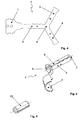
- the Indian FIG. 4 The area designated by the reference numeral 6 forms the tip of the contact pin 3 after bending deformation.
- the extended contact segment 5 is, as in the FIG. 2 shown partially embedded in the plastic base body 2 and extends into the interior of the connection cage 4 inside. Inside the connection cage 4, the extended contact segment 5 bears against the inner wall of the connection cage 4.
- the connection cable can be pressed by means of a clamping screw 8 against the connection surface 7 in order to produce the electrically conductive contact with the contact pin 3.
- two clamping screws 8 are shown. The upper of the two clamping screws is used to make the electrical contact.
- the lower clamping screw 8 is provided for fixing the sheath of the connection cable in the connection cage. Both clamping screws 8 are guided in a metallic threaded plate 9, which is inserted in the base body 2 in the region of the connection cage 4. At the lower end, the connection cage 4 has an insertion opening for the connecting cable.
- the two clamping screws 8 can be screwed transversely to the insertion direction of the connection cable.
- a fitting sleeve 10 is used in the insertion of the connection cage 4 .
- the Inner diameter of the adapter sleeve 10 substantially corresponds to the outer diameter of the jacket of the connection cable and thus serves as a strain relief.
- the adapter sleeve has, like the FIG. 2 shows, a through hole for the lower of the two clamping screws 8.
- the clamping screw thus fulfills a dual function. It sets the adapter sleeve in the insertion opening of the connection cage 4 and at the same time fixes the connecting cable to the plug 1.
- the expansion pin is tapered conically at its front end. The front end of the expansion pin 11a, 11b extends as the FIG. 2 shows, in the contact pin 3 inside.
- the expansion pin consists of a metallic spindle 11a and a handle portion 11b made of plastic. The spindle 11a is embedded in the plastic material of the grip part 11b.
- FIG. 2 shows the electrical connector according to the invention in the unstressed position in which the spindle 11a of the expansion pin is located only with the front tip within the expansion sleeve.
- the expansion sleeve 13 has an inner diameter which is significantly smaller than the outer diameter of the spindle 11a in the region of its shank.
- the expansion sleeve When screwing in the expansion pin 11a, 11b, the expansion sleeve is widened in accordance with the conical shape of the tip of the spindle 11a.
- the expansion sleeve 13 transmits a radially outwardly directed force to the contact segments 5 of the contact pin 3. This force acts as a contact pressure when pressing the outer surface of the contact pin 3 to the inner surface of an associated socket (not shown in detail in the drawings).
- a releasably connectable to the main body 2 latch 14 is provided.
- the bolt 14 has a locking projection 15 which is mounted in a on the handle portion 11b of the expansion pin mounted circumferential groove 16 (FIG. Fig. 3 ) intervenes.
- the bolt 14 thus prevents too wide unscrewing of the expansion pin 11a, 11b from the main body 2.
- the figures are, with respect to the longitudinal axis of the base body 2 angled portion of the base body, which forms the connection cage 4, separable.
- the figures show an integrally formed on the base body 2 safety pin 18, which prevents insertion of the contact pin 3 in a power outlet.
- FIGS. 7 and 8 is arranged in the interior of the contact pin a standing under radial prestress, elastically deformable spreader 19, which expands the contact pin 3 radially elastic.
- the spreader 19 ensures a good electrical connection characterized in that by radial expansion of the contact pin 3, the outer contact surface of the contact pin 3 is pressed against the inner contact surface of the corresponding socket and thereby the outer diameter of the deformable contact pin 3 automatically exactly fits the inner diameter of the socket.
- Almost any desired configurations and materials can be selected for the elastic expansion body 19 since the electrical properties of the connector are not or only slightly influenced by the properties of the expansion body 19.
- the expansion body 19 is an elongated plastic body having a cylindrical outer contour and rounded end faces. In a radial compression, the material of the expansion body 19 can escape in the axial direction of the contact pin 3.
- the spreader 19 is a preloaded cylindrical coil spring made of metal. It is important to tune the elasticity of the expansion body 19 and its bias so that the frictional forces when plugging into the socket are not too large, at the same time the quality of the electrical contact must not suffer.
Landscapes
- Details Of Connecting Devices For Male And Female Coupling (AREA)
- Connector Housings Or Holding Contact Members (AREA)
- Fishing Rods (AREA)
- Taps Or Cocks (AREA)
- Connections By Means Of Piercing Elements, Nuts, Or Screws (AREA)
Priority Applications (1)
| Application Number | Priority Date | Filing Date | Title |
|---|---|---|---|
| PL09707444T PL2240982T3 (pl) | 2008-02-06 | 2009-02-06 | Wtyczka bananowa |
Applications Claiming Priority (2)
| Application Number | Priority Date | Filing Date | Title |
|---|---|---|---|
| DE102008007866A DE102008007866A1 (de) | 2008-02-06 | 2008-02-06 | Bananenstecker |
| PCT/EP2009/000843 WO2009098075A1 (de) | 2008-02-06 | 2009-02-06 | Bananenstecker |
Publications (2)
| Publication Number | Publication Date |
|---|---|
| EP2240982A1 EP2240982A1 (de) | 2010-10-20 |
| EP2240982B1 true EP2240982B1 (de) | 2012-02-01 |
Family
ID=40481911
Family Applications (1)
| Application Number | Title | Priority Date | Filing Date |
|---|---|---|---|
| EP09707444A Not-in-force EP2240982B1 (de) | 2008-02-06 | 2009-02-06 | Bananenstecker |
Country Status (7)
| Country | Link |
|---|---|
| US (1) | US7955144B2 (pl) |
| EP (1) | EP2240982B1 (pl) |
| JP (1) | JP5345640B2 (pl) |
| AT (1) | ATE544203T1 (pl) |
| DE (1) | DE102008007866A1 (pl) |
| PL (1) | PL2240982T3 (pl) |
| WO (1) | WO2009098075A1 (pl) |
Families Citing this family (12)
| Publication number | Priority date | Publication date | Assignee | Title |
|---|---|---|---|---|
| DE102010023841A1 (de) | 2010-06-09 | 2011-12-15 | Pfisterer Kontaktsysteme Gmbh | Elektrisches Steckverbindungselement |
| USD720700S1 (en) * | 2012-09-11 | 2015-01-06 | Google Inc. | Banana plug adapter |
| DE102014005339B4 (de) | 2014-01-28 | 2022-06-09 | Wolfgang B. Thörner | Verfahren zur Herstellung eines Kontaktelements |
| FR3022408B1 (fr) * | 2014-06-12 | 2018-01-12 | Souriau | Douille de contact electrique a effort d’insertion reduit |
| CA2916781C (en) * | 2015-01-07 | 2018-04-24 | Appleton Grp Llc | A connector assembly having self-adjusting male and female connector elements |
| US9761993B2 (en) * | 2015-01-08 | 2017-09-12 | Westek Electronics, Inc. | Banana plug |
| DE102015006792B4 (de) * | 2015-05-27 | 2017-04-06 | Alexander Michel | Fixierungsstecker zum reversiblen Fixieren in einer Buchse sowie Verwendung des Fixierungssteckers zum Fixieren des Fixierungssteckers in einer Buchse |
| DE102015116818A1 (de) * | 2015-10-03 | 2017-04-06 | Harting Electric Gmbh & Co. Kg | Verbindungseinrichtung und Verfahren zum Herstellen einer elektrisch leitenden Verbindung zwischen einem elektrischen Leiter und einer technischen Einrichtung |
| DE102015116817A1 (de) * | 2015-10-03 | 2017-04-06 | Harting Electric Gmbh & Co. Kg | Verbindungseinrichtung und Verfahren zum Herstellen einer elektrisch leitenden Verbindung zwischen einem elektrischen Leiter und einer technischen Einrichtung |
| CN110190437B (zh) * | 2018-02-23 | 2021-07-30 | 中航光电科技股份有限公司 | 一种接触件及使用该接触件的连接器 |
| JP7398055B2 (ja) * | 2020-05-19 | 2023-12-14 | 株式会社オートネットワーク技術研究所 | 雄端子 |
| DE102020003770B4 (de) | 2020-06-19 | 2023-06-29 | Sbs Massenbachhausen Verwaltungs Gmbh | Elektrischer Kontakt |
Family Cites Families (22)
| Publication number | Priority date | Publication date | Assignee | Title |
|---|---|---|---|---|
| US2851669A (en) * | 1949-05-06 | 1958-09-09 | Richard C Koch | Expansion type connector plug |
| DE1186926B (de) | 1962-06-07 | 1965-02-11 | Sihn Kg Wilhelm Jun | Steckerstift fuer elektrische Stecker |
| US3234321A (en) * | 1963-03-14 | 1966-02-08 | Thomas & Betts Corp | Tubular tapered connectors |
| JPS513426Y1 (pl) * | 1974-04-18 | 1976-01-31 | ||
| DE2711859A1 (de) | 1977-03-18 | 1978-09-21 | Nicolay Gmbh | Verfahren zum herstellen eines kontaktorganes und ein damit hergestelltes kontaktorgan |
| GB1592848A (en) * | 1977-09-13 | 1981-07-08 | Strix Ltd | Male pin plug units |
| JPS56166682U (pl) * | 1980-05-15 | 1981-12-10 | ||
| JPS6121802Y2 (pl) * | 1981-03-02 | 1986-06-30 | ||
| US4384758A (en) * | 1981-12-17 | 1983-05-24 | Monster Cable Products, Inc. | Electrical connector |
| US4596440A (en) * | 1984-03-06 | 1986-06-24 | E. F. Johnson Company | Electrical probe contact |
| US4718865A (en) * | 1985-01-22 | 1988-01-12 | Electric Terminal Corporation | Insulated electrical plug |
| US4824405A (en) * | 1987-05-28 | 1989-04-25 | Ronald Derain | Self-locking electrical banana plug |
| US5011438A (en) * | 1989-11-28 | 1991-04-30 | Esoteric Audio Usa, Inc. | Method for manufacturing improved electrical connector |
| US5197908A (en) * | 1991-11-29 | 1993-03-30 | Gunnar Nelson | Connector |
| DE29504240U1 (de) | 1995-01-24 | 1995-06-29 | Thörner, Wolfgang B., 45149 Essen | Verspannbarer elektrischer Steckverbinder |
| DE29703602U1 (de) * | 1997-02-28 | 1997-05-15 | Thörner, Wolfgang B., 45149 Essen | Bananenstecker, insbesondere Lautsprecherstecker zur Verwendung an Hi-Fi-Anlagen |
| US5951337A (en) * | 1997-06-02 | 1999-09-14 | Desco Industries, Inc. | Damage-resistant electrical connector plug and combination |
| CN2553532Y (zh) * | 2002-06-26 | 2003-05-28 | 章鸿斌 | 一种香蕉插头 |
| JP2004146287A (ja) * | 2002-10-28 | 2004-05-20 | Matsushita Electric Works Ltd | プラグピン、及びその保持構造 |
| DE10258689B3 (de) * | 2002-12-13 | 2004-07-08 | Wolfgang B. THÖRNER | Koaxiale Steckverbindung |
| DE102004003651B4 (de) * | 2004-01-24 | 2013-04-18 | Wolfgang B. Thörner | Koaxialer Verbindungsstecker mit Hebei |
| US7758593B2 (en) * | 2006-05-04 | 2010-07-20 | Ethicon Endo-Surgery, Inc. | Medical instrument handle and medical instrument having same |
-
2008
- 2008-02-06 DE DE102008007866A patent/DE102008007866A1/de not_active Withdrawn
-
2009
- 2009-02-06 JP JP2010545409A patent/JP5345640B2/ja not_active Expired - Fee Related
- 2009-02-06 AT AT09707444T patent/ATE544203T1/de active
- 2009-02-06 US US12/735,664 patent/US7955144B2/en not_active Expired - Fee Related
- 2009-02-06 WO PCT/EP2009/000843 patent/WO2009098075A1/de not_active Ceased
- 2009-02-06 PL PL09707444T patent/PL2240982T3/pl unknown
- 2009-02-06 EP EP09707444A patent/EP2240982B1/de not_active Not-in-force
Also Published As
| Publication number | Publication date |
|---|---|
| JP2011511423A (ja) | 2011-04-07 |
| DE102008007866A1 (de) | 2009-08-13 |
| US7955144B2 (en) | 2011-06-07 |
| EP2240982A1 (de) | 2010-10-20 |
| JP5345640B2 (ja) | 2013-11-20 |
| ATE544203T1 (de) | 2012-02-15 |
| US20110045711A1 (en) | 2011-02-24 |
| PL2240982T3 (pl) | 2012-08-31 |
| WO2009098075A1 (de) | 2009-08-13 |
Similar Documents
| Publication | Publication Date | Title |
|---|---|---|
| EP2240982B1 (de) | Bananenstecker | |
| DE60128637T2 (de) | Einstufiger Verbinder | |
| EP1317025B1 (de) | Belastbare Steckeranordnung für Datenkabel, insbesondere RJ-45-Verbinder | |
| DE9116154U1 (de) | Vorrichtung für den Anschluß eines Kabelendes | |
| DE2343030A1 (de) | Anschlussvorrichtung fuer koaxialkabel | |
| DE2647043C2 (de) | Zugentlastungsvorrichtung für eine Kabeleinführung in ein Gehäuse eines elektrischen Gerätes | |
| DE69817200T2 (de) | Steckverbinder mit einer integralen schalter betätigungskurve | |
| DE10258689B3 (de) | Koaxiale Steckverbindung | |
| WO2003067719A1 (de) | Polklemme | |
| DE4420859A1 (de) | Hülsenhalter für ein optisches Verbindungsstück | |
| DE202011002287U1 (de) | Kabelverschraubung für abgeschirmte Leitungen | |
| EP1467441A2 (de) | Schnellanschliessbare Steckverbindung in Spannzangentechnik | |
| DE102004043518B3 (de) | Vorrichtung zum Anschluss eines Koaxialkabels an ein Gehäuse | |
| DE1953302A1 (de) | Elektrisches Kupplungsglied | |
| EP2451021A2 (de) | Gehäuse für einen Steckverbinder | |
| DE4210491C2 (de) | Vorrichtung zur Herstellung einer lösbaren Verbindung zwischen einer Signalleitung und einer elektrisch leitenden Anschlußbuchse in einem Bauteil eines Mittelspannungs- oder Hochspannungsenergieversorgungssystems | |
| DE102014222879A1 (de) | Abdeckelement für einen elektrischen Verbinder | |
| DE10304480B4 (de) | Anschlussklemmvorrichtung zum Anschluss eines Ringkabelschuhs und zugehöriges elektrisches Gerät | |
| DE10323616A1 (de) | Schnellanschließbare Steckverbindung in Spannzangentechnik | |
| DE202012101303U1 (de) | Steckverbindergehäuse | |
| DE10251120A1 (de) | Kabelstecker | |
| DE102011106736A1 (de) | Gehäusestecker und Gehäusebuchse sowie Werkzeug dafür | |
| EP2276130A2 (de) | Endgehäuse für ein elektrisches Kabel | |
| DE2606917C3 (de) | Elektrischer Koaxialsteckverbinder | |
| DE20206797U1 (de) | Adapter für einen optischen Faserstecker |
Legal Events
| Date | Code | Title | Description |
|---|---|---|---|
| PUAI | Public reference made under article 153(3) epc to a published international application that has entered the european phase |
Free format text: ORIGINAL CODE: 0009012 |
|
| 17P | Request for examination filed |
Effective date: 20100906 |
|
| AK | Designated contracting states |
Kind code of ref document: A1 Designated state(s): AT BE BG CH CY CZ DE DK EE ES FI FR GB GR HR HU IE IS IT LI LT LU LV MC MK MT NL NO PL PT RO SE SI SK TR |
|
| AX | Request for extension of the european patent |
Extension state: AL BA RS |
|
| DAX | Request for extension of the european patent (deleted) | ||
| GRAP | Despatch of communication of intention to grant a patent |
Free format text: ORIGINAL CODE: EPIDOSNIGR1 |
|
| GRAS | Grant fee paid |
Free format text: ORIGINAL CODE: EPIDOSNIGR3 |
|
| GRAA | (expected) grant |
Free format text: ORIGINAL CODE: 0009210 |
|
| AK | Designated contracting states |
Kind code of ref document: B1 Designated state(s): AT BE BG CH CY CZ DE DK EE ES FI FR GB GR HR HU IE IS IT LI LT LU LV MC MK MT NL NO PL PT RO SE SI SK TR |
|
| REG | Reference to a national code |
Ref country code: GB Ref legal event code: FG4D Free format text: NOT ENGLISH |
|
| REG | Reference to a national code |
Ref country code: AT Ref legal event code: REF Ref document number: 544203 Country of ref document: AT Kind code of ref document: T Effective date: 20120215 Ref country code: CH Ref legal event code: EP |
|
| REG | Reference to a national code |
Ref country code: DE Ref legal event code: R096 Ref document number: 502009002626 Country of ref document: DE Effective date: 20120329 |
|
| REG | Reference to a national code |
Ref country code: NL Ref legal event code: T3 |
|
| LTIE | Lt: invalidation of european patent or patent extension |
Effective date: 20120201 |
|
| PG25 | Lapsed in a contracting state [announced via postgrant information from national office to epo] |
Ref country code: NO Free format text: LAPSE BECAUSE OF FAILURE TO SUBMIT A TRANSLATION OF THE DESCRIPTION OR TO PAY THE FEE WITHIN THE PRESCRIBED TIME-LIMIT Effective date: 20120501 Ref country code: LT Free format text: LAPSE BECAUSE OF FAILURE TO SUBMIT A TRANSLATION OF THE DESCRIPTION OR TO PAY THE FEE WITHIN THE PRESCRIBED TIME-LIMIT Effective date: 20120201 Ref country code: HR Free format text: LAPSE BECAUSE OF FAILURE TO SUBMIT A TRANSLATION OF THE DESCRIPTION OR TO PAY THE FEE WITHIN THE PRESCRIBED TIME-LIMIT Effective date: 20120201 Ref country code: IS Free format text: LAPSE BECAUSE OF FAILURE TO SUBMIT A TRANSLATION OF THE DESCRIPTION OR TO PAY THE FEE WITHIN THE PRESCRIBED TIME-LIMIT Effective date: 20120601 |
|
| PGFP | Annual fee paid to national office [announced via postgrant information from national office to epo] |
Ref country code: TR Payment date: 20120426 Year of fee payment: 4 Ref country code: BE Payment date: 20120427 Year of fee payment: 4 |
|
| REG | Reference to a national code |
Ref country code: IE Ref legal event code: FD4D |
|
| PG25 | Lapsed in a contracting state [announced via postgrant information from national office to epo] |
Ref country code: LV Free format text: LAPSE BECAUSE OF FAILURE TO SUBMIT A TRANSLATION OF THE DESCRIPTION OR TO PAY THE FEE WITHIN THE PRESCRIBED TIME-LIMIT Effective date: 20120201 Ref country code: PT Free format text: LAPSE BECAUSE OF FAILURE TO SUBMIT A TRANSLATION OF THE DESCRIPTION OR TO PAY THE FEE WITHIN THE PRESCRIBED TIME-LIMIT Effective date: 20120601 Ref country code: GR Free format text: LAPSE BECAUSE OF FAILURE TO SUBMIT A TRANSLATION OF THE DESCRIPTION OR TO PAY THE FEE WITHIN THE PRESCRIBED TIME-LIMIT Effective date: 20120502 Ref country code: FI Free format text: LAPSE BECAUSE OF FAILURE TO SUBMIT A TRANSLATION OF THE DESCRIPTION OR TO PAY THE FEE WITHIN THE PRESCRIBED TIME-LIMIT Effective date: 20120201 |
|
| PGFP | Annual fee paid to national office [announced via postgrant information from national office to epo] |
Ref country code: FR Payment date: 20120530 Year of fee payment: 4 Ref country code: PL Payment date: 20120427 Year of fee payment: 4 |
|
| REG | Reference to a national code |
Ref country code: PL Ref legal event code: T3 |
|
| PG25 | Lapsed in a contracting state [announced via postgrant information from national office to epo] |
Ref country code: CY Free format text: LAPSE BECAUSE OF FAILURE TO SUBMIT A TRANSLATION OF THE DESCRIPTION OR TO PAY THE FEE WITHIN THE PRESCRIBED TIME-LIMIT Effective date: 20120201 Ref country code: MC Free format text: LAPSE BECAUSE OF NON-PAYMENT OF DUE FEES Effective date: 20120229 |
|
| PG25 | Lapsed in a contracting state [announced via postgrant information from national office to epo] |
Ref country code: CZ Free format text: LAPSE BECAUSE OF FAILURE TO SUBMIT A TRANSLATION OF THE DESCRIPTION OR TO PAY THE FEE WITHIN THE PRESCRIBED TIME-LIMIT Effective date: 20120201 Ref country code: SI Free format text: LAPSE BECAUSE OF FAILURE TO SUBMIT A TRANSLATION OF THE DESCRIPTION OR TO PAY THE FEE WITHIN THE PRESCRIBED TIME-LIMIT Effective date: 20120201 Ref country code: RO Free format text: LAPSE BECAUSE OF FAILURE TO SUBMIT A TRANSLATION OF THE DESCRIPTION OR TO PAY THE FEE WITHIN THE PRESCRIBED TIME-LIMIT Effective date: 20120201 Ref country code: SE Free format text: LAPSE BECAUSE OF FAILURE TO SUBMIT A TRANSLATION OF THE DESCRIPTION OR TO PAY THE FEE WITHIN THE PRESCRIBED TIME-LIMIT Effective date: 20120201 Ref country code: DK Free format text: LAPSE BECAUSE OF FAILURE TO SUBMIT A TRANSLATION OF THE DESCRIPTION OR TO PAY THE FEE WITHIN THE PRESCRIBED TIME-LIMIT Effective date: 20120201 Ref country code: EE Free format text: LAPSE BECAUSE OF FAILURE TO SUBMIT A TRANSLATION OF THE DESCRIPTION OR TO PAY THE FEE WITHIN THE PRESCRIBED TIME-LIMIT Effective date: 20120201 Ref country code: IE Free format text: LAPSE BECAUSE OF FAILURE TO SUBMIT A TRANSLATION OF THE DESCRIPTION OR TO PAY THE FEE WITHIN THE PRESCRIBED TIME-LIMIT Effective date: 20120201 |
|
| PG25 | Lapsed in a contracting state [announced via postgrant information from national office to epo] |
Ref country code: SK Free format text: LAPSE BECAUSE OF FAILURE TO SUBMIT A TRANSLATION OF THE DESCRIPTION OR TO PAY THE FEE WITHIN THE PRESCRIBED TIME-LIMIT Effective date: 20120201 Ref country code: IT Free format text: LAPSE BECAUSE OF FAILURE TO SUBMIT A TRANSLATION OF THE DESCRIPTION OR TO PAY THE FEE WITHIN THE PRESCRIBED TIME-LIMIT Effective date: 20120201 |
|
| PLBE | No opposition filed within time limit |
Free format text: ORIGINAL CODE: 0009261 |
|
| STAA | Information on the status of an ep patent application or granted ep patent |
Free format text: STATUS: NO OPPOSITION FILED WITHIN TIME LIMIT |
|
| 26N | No opposition filed |
Effective date: 20121105 |
|
| PG25 | Lapsed in a contracting state [announced via postgrant information from national office to epo] |
Ref country code: MK Free format text: LAPSE BECAUSE OF FAILURE TO SUBMIT A TRANSLATION OF THE DESCRIPTION OR TO PAY THE FEE WITHIN THE PRESCRIBED TIME-LIMIT Effective date: 20120201 |
|
| REG | Reference to a national code |
Ref country code: DE Ref legal event code: R097 Ref document number: 502009002626 Country of ref document: DE Effective date: 20121105 |
|
| PG25 | Lapsed in a contracting state [announced via postgrant information from national office to epo] |
Ref country code: ES Free format text: LAPSE BECAUSE OF FAILURE TO SUBMIT A TRANSLATION OF THE DESCRIPTION OR TO PAY THE FEE WITHIN THE PRESCRIBED TIME-LIMIT Effective date: 20120512 |
|
| PGFP | Annual fee paid to national office [announced via postgrant information from national office to epo] |
Ref country code: GB Payment date: 20130228 Year of fee payment: 5 |
|
| PGFP | Annual fee paid to national office [announced via postgrant information from national office to epo] |
Ref country code: NL Payment date: 20130228 Year of fee payment: 5 |
|
| PG25 | Lapsed in a contracting state [announced via postgrant information from national office to epo] |
Ref country code: BG Free format text: LAPSE BECAUSE OF FAILURE TO SUBMIT A TRANSLATION OF THE DESCRIPTION OR TO PAY THE FEE WITHIN THE PRESCRIBED TIME-LIMIT Effective date: 20120501 Ref country code: MT Free format text: LAPSE BECAUSE OF FAILURE TO SUBMIT A TRANSLATION OF THE DESCRIPTION OR TO PAY THE FEE WITHIN THE PRESCRIBED TIME-LIMIT Effective date: 20120201 |
|
| BERE | Be: lapsed |
Owner name: THORNER, WOLFGANG B. Effective date: 20130228 |
|
| REG | Reference to a national code |
Ref country code: CH Ref legal event code: PL |
|
| PG25 | Lapsed in a contracting state [announced via postgrant information from national office to epo] |
Ref country code: LI Free format text: LAPSE BECAUSE OF NON-PAYMENT OF DUE FEES Effective date: 20130228 Ref country code: CH Free format text: LAPSE BECAUSE OF NON-PAYMENT OF DUE FEES Effective date: 20130228 |
|
| REG | Reference to a national code |
Ref country code: FR Ref legal event code: ST Effective date: 20131031 |
|
| PG25 | Lapsed in a contracting state [announced via postgrant information from national office to epo] |
Ref country code: BE Free format text: LAPSE BECAUSE OF NON-PAYMENT OF DUE FEES Effective date: 20130228 Ref country code: FR Free format text: LAPSE BECAUSE OF NON-PAYMENT OF DUE FEES Effective date: 20130228 |
|
| PG25 | Lapsed in a contracting state [announced via postgrant information from national office to epo] |
Ref country code: PL Free format text: LAPSE BECAUSE OF NON-PAYMENT OF DUE FEES Effective date: 20130206 Ref country code: LU Free format text: LAPSE BECAUSE OF NON-PAYMENT OF DUE FEES Effective date: 20120206 |
|
| REG | Reference to a national code |
Ref country code: PL Ref legal event code: LAPE |
|
| PG25 | Lapsed in a contracting state [announced via postgrant information from national office to epo] |
Ref country code: HU Free format text: LAPSE BECAUSE OF FAILURE TO SUBMIT A TRANSLATION OF THE DESCRIPTION OR TO PAY THE FEE WITHIN THE PRESCRIBED TIME-LIMIT Effective date: 20090206 |
|
| REG | Reference to a national code |
Ref country code: NL Ref legal event code: V1 Effective date: 20140901 |
|
| GBPC | Gb: european patent ceased through non-payment of renewal fee |
Effective date: 20140206 |
|
| PG25 | Lapsed in a contracting state [announced via postgrant information from national office to epo] |
Ref country code: NL Free format text: LAPSE BECAUSE OF NON-PAYMENT OF DUE FEES Effective date: 20140901 |
|
| PG25 | Lapsed in a contracting state [announced via postgrant information from national office to epo] |
Ref country code: GB Free format text: LAPSE BECAUSE OF NON-PAYMENT OF DUE FEES Effective date: 20140206 |
|
| REG | Reference to a national code |
Ref country code: AT Ref legal event code: MM01 Ref document number: 544203 Country of ref document: AT Kind code of ref document: T Effective date: 20140206 |
|
| PG25 | Lapsed in a contracting state [announced via postgrant information from national office to epo] |
Ref country code: AT Free format text: LAPSE BECAUSE OF NON-PAYMENT OF DUE FEES Effective date: 20140206 |
|
| PG25 | Lapsed in a contracting state [announced via postgrant information from national office to epo] |
Ref country code: TR Free format text: LAPSE BECAUSE OF NON-PAYMENT OF DUE FEES Effective date: 20130206 |
|
| PGFP | Annual fee paid to national office [announced via postgrant information from national office to epo] |
Ref country code: DE Payment date: 20180219 Year of fee payment: 10 |
|
| REG | Reference to a national code |
Ref country code: DE Ref legal event code: R119 Ref document number: 502009002626 Country of ref document: DE |
|
| PG25 | Lapsed in a contracting state [announced via postgrant information from national office to epo] |
Ref country code: DE Free format text: LAPSE BECAUSE OF NON-PAYMENT OF DUE FEES Effective date: 20190903 |