EP2233987A2 - Belichtungsvorrichtung und Bilderzeugungsgerät - Google Patents
Belichtungsvorrichtung und Bilderzeugungsgerät Download PDFInfo
- Publication number
- EP2233987A2 EP2233987A2 EP10156197A EP10156197A EP2233987A2 EP 2233987 A2 EP2233987 A2 EP 2233987A2 EP 10156197 A EP10156197 A EP 10156197A EP 10156197 A EP10156197 A EP 10156197A EP 2233987 A2 EP2233987 A2 EP 2233987A2
- Authority
- EP
- European Patent Office
- Prior art keywords
- light
- exposure
- exposure head
- temperature
- heads
- Prior art date
- Legal status (The legal status is an assumption and is not a legal conclusion. Google has not performed a legal analysis and makes no representation as to the accuracy of the status listed.)
- Withdrawn
Links
- 230000007423 decrease Effects 0.000 description 9
- 238000010586 diagram Methods 0.000 description 6
- 230000001788 irregular Effects 0.000 description 4
- 238000005401 electroluminescence Methods 0.000 description 2
- 238000000034 method Methods 0.000 description 2
- 238000003491 array Methods 0.000 description 1
- 239000003086 colorant Substances 0.000 description 1
- 230000003247 decreasing effect Effects 0.000 description 1
- 238000012986 modification Methods 0.000 description 1
- 230000004048 modification Effects 0.000 description 1
- 230000000630 rising effect Effects 0.000 description 1
Images





Classifications
-
- G—PHYSICS
- G03—PHOTOGRAPHY; CINEMATOGRAPHY; ANALOGOUS TECHNIQUES USING WAVES OTHER THAN OPTICAL WAVES; ELECTROGRAPHY; HOLOGRAPHY
- G03G—ELECTROGRAPHY; ELECTROPHOTOGRAPHY; MAGNETOGRAPHY
- G03G15/00—Apparatus for electrographic processes using a charge pattern
- G03G15/22—Apparatus for electrographic processes using a charge pattern involving the combination of more than one step according to groups G03G13/02 - G03G13/20
- G03G15/32—Apparatus for electrographic processes using a charge pattern involving the combination of more than one step according to groups G03G13/02 - G03G13/20 in which the charge pattern is formed dotwise, e.g. by a thermal head
- G03G15/326—Apparatus for electrographic processes using a charge pattern involving the combination of more than one step according to groups G03G13/02 - G03G13/20 in which the charge pattern is formed dotwise, e.g. by a thermal head by application of light, e.g. using a LED array
-
- G—PHYSICS
- G03—PHOTOGRAPHY; CINEMATOGRAPHY; ANALOGOUS TECHNIQUES USING WAVES OTHER THAN OPTICAL WAVES; ELECTROGRAPHY; HOLOGRAPHY
- G03G—ELECTROGRAPHY; ELECTROPHOTOGRAPHY; MAGNETOGRAPHY
- G03G15/00—Apparatus for electrographic processes using a charge pattern
- G03G15/04—Apparatus for electrographic processes using a charge pattern for exposing, i.e. imagewise exposure by optically projecting the original image on a photoconductive recording material
- G03G15/04036—Details of illuminating systems, e.g. lamps, reflectors
- G03G15/04045—Details of illuminating systems, e.g. lamps, reflectors for exposing image information provided otherwise than by directly projecting the original image onto the photoconductive recording material, e.g. digital copiers
- G03G15/04054—Details of illuminating systems, e.g. lamps, reflectors for exposing image information provided otherwise than by directly projecting the original image onto the photoconductive recording material, e.g. digital copiers by LED arrays
-
- G—PHYSICS
- G03—PHOTOGRAPHY; CINEMATOGRAPHY; ANALOGOUS TECHNIQUES USING WAVES OTHER THAN OPTICAL WAVES; ELECTROGRAPHY; HOLOGRAPHY
- G03G—ELECTROGRAPHY; ELECTROPHOTOGRAPHY; MAGNETOGRAPHY
- G03G2215/00—Apparatus for electrophotographic processes
- G03G2215/04—Arrangements for exposing and producing an image
- G03G2215/0402—Exposure devices
- G03G2215/0407—Light-emitting array or panel
- G03G2215/0409—Light-emitting diodes, i.e. LED-array
Definitions
- This invention relates to an exposure device and an image-forming apparatus.
- an image-writing device As an exposure device, an image-writing device has been known as disclosed in JP-A No. 2003-72146 .
- the image-writing device disclosed in JP-A No. 2003-72146 is configured by plural LED heads (light-emitting element array units) 503 arranged in a zig-zag manner along the axial direction (fast scanning direction) of a photosensitive body, and in which an LED write control circuit 501 divides the image data (image information) for each of the LED heads 503 and transfer the image data to the LED heads 503 in a manner of being deviated in time by the positions where they are to be focused on the photosensitive body in a direction of rotation.
- the quantity of light is corrected that is emitted by either one or both of the two light-emitting elements positioned at the seams of the LED heads 503 corresponding to part or whole of the divided positions of the image data.
- the present invention address to suppress irregular quantity of light among the exposure heads in a configuration equipped with plural exposure heads.
- a first aspect of the invention provides an exposure device including:
- Fig. 1 is a view schematically showing the whole configuration of the image-forming apparatus according to the exemplary embodiment.
- the image-forming apparatus is a color printer of the so-called tandem type, and is equipped with an intermediate transfer belt 40 as an intermediate transfer body as shown in Fig. 1 .
- the intermediate transfer belt 40 is formed like a ring, and is supported by plural support rolls 42 in a state of being tensioned.
- the outer circumference of the intermediate transfer belt 40 is surrounded by image-forming units 44C, 44M, 44Y and 44K corresponding to such colors as cyan (C), magenta (M), yellow (Y) and black (K) in this order along the direction in which the belt travels (counterclockwise direction in Fig. 1 ).
- the image-forming units 44C, 44M, 44Y and 44K each have a photosensitive body drum 46 as a photosensitive body.
- the photosensitive body drum 46 rotates in one direction (clockwise direction in Fig. 1 ).
- the photosensitive body is not limited to the photosensitive body drum 46 but may be, for example, a photosensitive body belt.
- the circumference of the photosensitive body drum 46 is surrounded by a charging device 50, an exposure device 12, a developing device 52, a primary transfer roll 54 as a primary transfer member and a cleaner 48 in this order in the direction of rotation.
- the surface of the photosensitive body drum 46 is uniformly charged by the charging device 50. Thereafter, the surface of the photosensitive body drum 46 is exposed to light by the exposure device 12 to form an electrostatic latent image.
- the electrostatic latent image formed by the exposure device 12 is developed by the developing device 52 to form a toner image which is transferred by the primary transfer roll 54 onto the intermediate transfer belt 40.
- the toner remaining on the photosensitive body drum 46 is removed by the cleaner 48.
- a fast scanning is effected along the axial direction of each photosensitive body drum 46 and a slow scanning is effected along the rotational direction (circumferential direction) of the photosensitive body drum 46.
- a recording medium P (e.g., paper) on which image is to be formed is held in a recording medium-holding portion 57.
- the recording medium P fed by the feed roll 56 is conveyed by plural conveyer rolls 58 along a passage represented by a broken line in the drawing.
- the recording medium P conveyed by the conveyer rolls 58 is sent to a secondary transfer position between a secondary transfer roll 60 which is a secondary transfer member and an opposing roll 63 that is opposing thereto.
- a color image on the intermediate transfer belt 40 is collectively transferred (secondarily transferred) onto the recording medium P conveyed to the secondary transfer position.
- the recording medium P on which the color image is transferred is conveyed by a paper conveyer system 62 to a fixing device 64 where the image is fixed (heated, pressed, etc.), and is discharged to a discharge portion that is not shown.
- the image-forming apparatus 10 is not limited to the above configuration, but can be configured in a variety of ways.
- the image-forming apparatus 10 may be, for example, an image-forming apparatus of the direct transfer type without having intermediate transfer member.
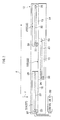
- Fig. 2 is a view schematically showing the configuration of the exposure device 12.
- the exposure device 12 of each color has a frame 14 formed in an elongated shape in one direction (X-direction in Fig. 2 ).
- Plural exposure heads 22 are provided on the frame 14 being arranged in one direction (X-direction in Fig. 2 ).
- the one direction in which the exposure heads 22 are arranged is a fast scanning direction.
- the direction (Y-direction in Fig. 2 ) at right angles with the one direction is a slow scanning direction.
- the plural exposure heads 22 are configured by three exposure heads, i.e., exposure head 22A, exposure head 22B and exposure head 22C.
- the number of the exposure heads 22 may be plural, such as 2 or 4 or more.
- the exposure heads 22 are alternately arranged in a zig-zag manner. Concretely, the exposure head 22B is arranged being deviated toward one side of the exposure head 22A in the slow scanning direction (Y-direction in Fig. 2 ). If viewed from the slow scanning direction, the exposure head 22A and the exposure head 22B are overlapped one upon the other at their end portions.
- the exposure head 22C is arranged as being deviated toward the other side of the exposure head 22B in the slow scanning direction (Y-direction in Fig. 2 ). If viewed from the slow scanning direction, the exposure head 22B and the exposure head 22C are overlapped one upon the other at their end portions.
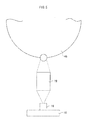
- the exposure heads 22 may be arranged stepwise as shown in Fig. 3 .
- the exposure head 22B is arranged being deviated toward one side of the exposure head 22A in the slow scanning direction (Y-direction in Fig. 3 ). If viewed from the slow scanning direction, the exposure head 22A and the exposure head 22B are overlapped one upon the other at their end portions.
- the exposure head 22C is arranged as being deviated toward one side of the exposure head 22B in the slow scanning direction (Y-direction in Fig. 3 ). If viewed from the slow scanning direction, the exposure head 22B and the exposure head 22C are overlapped one upon the other at their end portions.
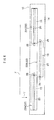
- Each exposure head 22 has a base plate 16 formed in a shape elongated in the fast scanning direction as shown in Figs. 2 and 4 .
- LED chips 18 which are light-emitting elements are arranged in a plural number on the base plate 16 in the fast scanning direction to meet the number of the pixels (number of dots).
- driver ICs 24 are provided in a plural number on the base plate 16 as drive circuits for driving the LED chips 18.
- a selfoc lens array 20 configured by arranging plural rod lenses 20A.
- the rod lenses 20A are two-dimensionally arranged so that an erect image is focused at an equal magnification by plural (six in this exemplary embodiment) rod lenses 20A for each dot. Therefore, the light emitted from each LED chip 18 is focused on the surface of the photosensitive body drum 46 through plural corresponding selfoc lens arrays 20. Thus, the photosensitive body drum 46 is exposed to light emitted from the LEDs 18, and a latent image is formed therein.
- This exemplary embodiment uses LEDs as light-emitting elements. Not being limited thereto only, however, it is also allowable to use any other light-emitting elements such as EL (electro-luminescence) elements.
- EL electro-luminescence
- Each exposure head 22 has temperature-detecting units 26 capable of detecting the temperature provided on the base plate 16.
- the temperature-detecting units 26 are mounted on the surface of the base plate 16 at both end portions of the exposure head 22 in a direction in which the LED chips 18 are arranged. That is, the temperature-detecting units 26 are arranged at both end portions of the base plate 16 in the lengthwise direction thereof (fast scanning direction). Concretely, the temperature-detecting units 26 are arranged on the outer sides of the LED chips 18 in the fast scanning direction.
- Positions where the temperature-detecting units 26 are arranged are not limited to the front surface of the base plate 16 but may be on the back surface of the base plate 16 on the side opposite to the side on where the LED chips 18 are mounted.
- the temperature-detecting units 26 are for grasping a change in the temperature of the LED chips 18 at the end portions in the fast scanning direction, and may be disposed near the LED chips 18 at both end portions in the fast scanning direction so as to grasp a change in the temperature of the LED chips 18 at the end portions in the fast scanning direction.
- the temperature-detecting units 26 may not be arranged on the outer sides of the LED chips 18 in the fast scanning direction.
- the temperature-detecting units 26 may be arranged being deviated toward one side of the LED chips 18 in the slow scanning direction (Y-direction in Fig. 2 ). If viewed from the slow scanning direction, further, the temperature-detecting units 26 may be arranged being overlapped on the end portions of the LED chips 18.
- the temperature-detecting units 26 maybe arranged just on the back surface at the ends of the LED chips 18.
- temperature-detecting units 26 may be provided on the driver ICs 24 instead of on the base plate 16.
- the two temperature detecting units 26 arranged at end portions of the base plate 16 can be selectively used for detecting the temperature.
- the temperature detecting unit 26 on the side where the other exposure head 22 is arranged is selectively used for detecting the temperature.
- the exposure head 22A selectively uses either one of the two temperature-detecting units 26, i.e., uses the temperature-detecting unit 26 on the side of the exposure head 22B (right side in Fig. 2 ) for detecting the temperature.
- the exposure head 22B uses both of the two temperature detectors 26 for actually the temperature.
- the exposure head 22C uses one of the two temperature-detecting units 26, i.e., uses the temperature-detecting unit 26 on the side of the exposure head 22B (left side in Fig. 2 ) for detecting the temperature.
- thermoelectric sensors 26 there can be used, for example, thermistors.
- the exposure device 12 has a control unit 28 as a correction unit for correcting the quantities of light from the exposure heads 22 based on the temperature data detected by the temperature-detecting units 26.
- the control unit 28 is connected to the temperature-detecting units 26, and the data of temperature detected by the temperature-detecting units 26 are obtained by the control unit 28.
- Each exposure head 22 is provided with an EEPROM 30 as a storage unit for storing correction data for correcting the quantity of light from the exposure head 22.
- control unit 28 corrects the quantities of light from the exposure heads 22 based on the temperature data detected by the temperature-detecting units 26.
- the temperature-detecting units 26 may be arranged on the frame 14 as shown in Fig. 6 instead of being arranged on the exposure head 22. In this configuration, of both end portions of the exposure head 22 in the direction in which the LED chips 18 are arranged, the temperature-detecting units 26 are arranged at an end portion on the side where the other exposure head 22 is arranged.
- Described below is a case where the temperatures of the exposure heads 22 are elevated, and the quantities of light from the exposure heads 22 are decreasing at different rates as shown in Fig. 7 .
- a decrease in the quantity of light per a temperature rise of 1°C is regarded to be a light quantity down coefficient, its absolute value increases in order of light quantity down coefficient Kb of the exposure head 22B, light quantity down coefficient Ka of the exposure head 22A and light quantity down coefficient Kc of the exposure head 22C.
- the temperature rise can be attributed to heat generated by the exposure heads 22 as they emit light and to heat generated by the external drive units.
- the quantities of light from the exposure head 22A more decreases than that of from the exposure head 22B, and the quantity of light from the exposure head 22C more decreases than that of from the exposure head 22A (see thick lines C). Therefore, the quantities of light more vary among the exposure heads 22.
- Fig. 8A shows an example of when the temperatures are evenly elevated in the exposure heads 22.
- the density of image becomes irregular as shown in Fig. 8B .
- the temperature-detecting units 26 arranged at the end portions of the exposure heads 22 detect the temperatures. Based on the temperature data detected by the temperature-detecting units 26, therefore, the control unit 28 corrects the quantities of light from the exposure heads 22 in accordance with the light quantity down coefficients of the exposure heads 22 as shown in Fig. 9A .
- the exposure head 22A has a light quantity down coefficient larger than that of the exposure head 22B and, therefore, has a light quantity correction value larger than that of the exposure head 228.
- the exposure head 22C has a light quantity down coefficient larger than that of the exposure head 22A and, therefore, has a light quantity correction value larger than that of the exposure head 22A.
- the correction value increases with an increase in the light quantity down coefficient.
- thick lines D represent light quantities of the exposure heads 22 after corrected
- dotted lines E represent light quantities of the exposure heads 22 after the temperatures are elevated
- dotted lines F represent light quantities of when the temperatures are further elevated in the exposure heads 22.
- the image can be formed maintaining a uniform density as shown in Fig. 9B .
- Figs. 10 and 11 illustrate a case of correcting the light quantities using as a reference the end portion of the exposure head 22B on the side of the exposure head 22A.
- the exposure heads 22 emit light at constant quantities (see thick lines G in Fig. 10 ). As the temperatures of the exposure heads 22 rise, the quantities of light unevenly decrease in the fast scanning direction as represented by dotted lines I in Fig. 10 .
- the exposure head 22A has a light quantity down coefficient Ka.
- the temperature rise detected by the temperature-detecting unit 26 at an end of the right side (on the side of the exposure head 22B) is denoted by Ra
- the quantity of light after the temperature is elevated at the end portion becomes RaKa with the initial light quantity being 0.
- the exposure head 22B has a light quantity down coefficient Kb.
- Kb the temperature rise detected by the temperature-detecting unit 26 at an end of the left side (on the side of the exposure head 22A)
- Lb the quantity of light after the temperature is elevated at the end portion becomes LbKb.
- Rb the temperature rise detected by the temperature-detecting unit 26 at an end on the right side of the exposure head 22B (on the side of the exposure head 22C)
- RbKb the quantity of light after the temperature is elevated at the end portion becomes RbKb with the initial light quantity being 0.
- the exposure head 22C has a light quantity down coefficient Kc.
- Kc the temperature rise detected by the temperature-detecting unit 26 at an end of the left side (on the side of the exposure head 22B)
- LcKc the quantity of light after the temperature is elevated at the end portion becomes LcKc with the initial light quantity being 0.
- the end on the left side of the exposure head 22B is used as a reference, and the end portion is so corrected that the quantity of light returns to the initial quantity of light. Therefore, the light quantity correction value of the exposure head 22B becomes -LbKb. The temperature correction value at this moment becomes -Lb.
- the end portion on the right side of the exposure head 22A is so corrected that the quantity of light returns to the initial quantity of light.
- the light quantity correction value becomes -RaKa.
- the temperature correction value at this moment becomes -Ra.
- the quantity of light after corrected becomes (Rb - Lb)Kb at the end portion on the right side of the exposure head 22B of which the quantity of light is corrected with the light quantity correction value -LbKb.
- the end portion on the left side of the exposure head 22C is so corrected that (Rb - Lb)Kb is assumed.
- the light quantity correction value becomes (Rb - Lb)Kb - LcKc.
- the temperature correction value at this moment becomes (Rb - Lb)Kb/Kc - Lc.
- the above correction eliminates a step in which the quantity of light sharply varies in the seam portions among the exposure heads 22, and suppresses irregular quantity of light. Therefore, the image is formed without causing conspicuous irregularity in the density.
- Figs. 12 and 13 are for illustrating a case of correcting the light quantities using the central portion of the exposure head 22B as a reference.
- the exposure heads 22 are emitting light at constant quantities (see thick lines K in Fig. 12 ). As the temperatures of the exposure heads 22 rise, the quantities of light unevenly decrease in the fast scanning direction as represented by dotted lines L in Fig. 12 .
- the exposure head 22A has a light quantity down coefficient Ka.
- the temperature rise detected by the temperature-detecting unit 26 at an end of the right side (on the side of the exposure head 22B) is denoted by Ra
- the quantity of light after the temperature is elevated at the end portion becomes RaKa with the initial light quantity being 0.
- the exposure head 22B has a light quantity down coefficient Kb.
- Kb the temperature rise detected by the temperature-detecting unit 26 at an end of the left side (on the side of the exposure head 22A)
- Lb the quantity of light after the temperature is elevated at the end portion becomes LbKb.
- Rb the temperature rise detected by the temperature-detecting unit 26 at an end on the right side of the exposure head 22B (on the side of the exposure head 22C)
- RbKb the quantity of light after the temperature is elevated at the end portion becomes RbKb with the initial light quantity being 0.
- the temperature rise at the central portion of the exposure head 22B is supposed to be an average value (Lb + Rb)/2 of the left side and the right side, the quantity of light after the temperature is elevated at the central portion becomes (Lb + Rb)Kb/2 with the initial light quantity being 0.
- the exposure head 22C has a light quantity down coefficient Kc.
- Kc the temperature rise detected by the temperature-detecting unit 26 at an end of the left side (on the side of the exposure head 22B)
- LcKc the quantity of light after the temperature is elevated at the end portion becomes LcKc with the initial light quantity being 0.
- the central portion of the exposure head 22B is used as a reference, and the central portion is so corrected that the quantity of light returns to the initial quantity of light. Therefore, the light quantity correction value of the exposure head 22B becomes -(Lb + Rb)Kb/2. The temperature correction value at this moment becomes -(Lb + Rb)/2.
- the quantity of light after corrected becomes (Lb - Rb)Kb/2 at the end portion on the left side of the exposure head 22B of which the quantity of light is corrected with the light quantity correction value -(Lb + Rb)Kb/2.
- the end portion on the right side of the exposure head 22A is so corrected that the quantity of light returns to (Lb - Rb)Kb/2.
- the light quantity correction value becomes (Lb - Rb)Kb/2 - RaKa.
- the temperature correction value at this moment becomes (Lb - Rb)Kb/2Ka - Ra.
- the quantity of light after corrected becomes (Rb - Lb)Kb/2 at the end portion on the right side of the exposure head 22B of which the quantity of light is corrected with the light quantity correction value -(Lb + Rb)Kb/2.
- the end portion on the left side of the exposure head 22C is so corrected that the quantity of light becomes (Rb - Lb)Kb/2.
- the light quantity correction value becomes (Rb - Lb)Kb/2 - LcKc.
- the temperature correction value at this moment becomes (Rb - Lb)Kb/2Kc - Lc.
- the above correction eliminates a step in which the quantity of light sharply varies in the seam portions among the exposure heads 22, and suppresses irregular quantity of light. Therefore, the image is formed without causing conspicuous irregularity in the density.
- the present invention is not limited to the above exemplary embodiment only but can be varied, modified or improved in various other ways.
Landscapes
- Physics & Mathematics (AREA)
- General Physics & Mathematics (AREA)
- Printers Or Recording Devices Using Electromagnetic And Radiation Means (AREA)
- Exposure Or Original Feeding In Electrophotography (AREA)
- Facsimile Heads (AREA)
Applications Claiming Priority (1)
| Application Number | Priority Date | Filing Date | Title |
|---|---|---|---|
| JP2009076990A JP5359448B2 (ja) | 2009-03-26 | 2009-03-26 | 露光装置及び画像形成装置 |
Publications (2)
| Publication Number | Publication Date |
|---|---|
| EP2233987A2 true EP2233987A2 (de) | 2010-09-29 |
| EP2233987A3 EP2233987A3 (de) | 2011-04-27 |
Family
ID=42084501
Family Applications (1)
| Application Number | Title | Priority Date | Filing Date |
|---|---|---|---|
| EP10156197A Withdrawn EP2233987A3 (de) | 2009-03-26 | 2010-03-11 | Belichtungsvorrichtung und Bilderzeugungsgerät |
Country Status (3)
| Country | Link |
|---|---|
| US (1) | US8305407B2 (de) |
| EP (1) | EP2233987A3 (de) |
| JP (1) | JP5359448B2 (de) |
Families Citing this family (5)
| Publication number | Priority date | Publication date | Assignee | Title |
|---|---|---|---|---|
| US9405254B2 (en) | 2013-11-26 | 2016-08-02 | Xerox Corporation | Device for uniform light intensity generation |
| JP6776650B2 (ja) * | 2016-06-23 | 2020-10-28 | 富士ゼロックス株式会社 | プリントヘッド及び画像形成装置 |
| JP7205266B2 (ja) * | 2019-02-05 | 2023-01-17 | コニカミノルタ株式会社 | 光書き込み装置および画像形成装置 |
| JP7694260B2 (ja) | 2021-08-25 | 2025-06-18 | 富士フイルムビジネスイノベーション株式会社 | 発光装置、光計測装置及び画像形成装置 |
| JP7793356B2 (ja) * | 2021-12-13 | 2026-01-05 | キヤノン株式会社 | 露光ヘッド及び画像形成装置 |
Family Cites Families (7)
| Publication number | Priority date | Publication date | Assignee | Title |
|---|---|---|---|---|
| JPH10332494A (ja) * | 1997-06-03 | 1998-12-18 | Oki Data:Kk | 温度検出回路、駆動装置及びプリンタ |
| JP2003072146A (ja) | 2001-09-06 | 2003-03-12 | Ricoh Co Ltd | 画像書込装置および画像形成装置 |
| JP4626272B2 (ja) * | 2004-11-10 | 2011-02-02 | 富士ゼロックス株式会社 | 画像形成装置 |
| JP5066953B2 (ja) * | 2007-03-07 | 2012-11-07 | 富士ゼロックス株式会社 | 露光装置および画像形成装置 |
| JP2008221721A (ja) * | 2007-03-14 | 2008-09-25 | Fuji Xerox Co Ltd | 画像形成装置および露光装置 |
| JP2008229908A (ja) * | 2007-03-16 | 2008-10-02 | Fuji Xerox Co Ltd | 露光装置および画像形成装置 |
| JP4420949B2 (ja) | 2007-09-20 | 2010-02-24 | 株式会社沖データ | 駆動装置、駆動回路、ledヘッド及び画像形成装置 |
-
2009
- 2009-03-26 JP JP2009076990A patent/JP5359448B2/ja active Active
- 2009-08-19 US US12/543,772 patent/US8305407B2/en not_active Expired - Fee Related
-
2010
- 2010-03-11 EP EP10156197A patent/EP2233987A3/de not_active Withdrawn
Non-Patent Citations (1)
| Title |
|---|
| None |
Also Published As
| Publication number | Publication date |
|---|---|
| US20100245794A1 (en) | 2010-09-30 |
| US8305407B2 (en) | 2012-11-06 |
| JP2010228213A (ja) | 2010-10-14 |
| JP5359448B2 (ja) | 2013-12-04 |
| EP2233987A3 (de) | 2011-04-27 |
Similar Documents
| Publication | Publication Date | Title |
|---|---|---|
| EP2233987A2 (de) | Belichtungsvorrichtung und Bilderzeugungsgerät | |
| CN101032890A (zh) | 发光装置、电子设备及驱动方法 | |
| JP6225723B2 (ja) | 光走査ヘッド、画像処理装置、光量補正制御プログラム | |
| JP6825416B2 (ja) | 光書込み装置およびそれを備える画像形成装置 | |
| US9588455B2 (en) | Image forming apparatus | |
| US20220091533A1 (en) | Light emitting device and image forming apparatus | |
| US20100225730A1 (en) | Exposure device, image forming apparatus and computer-readable medium | |
| JP5114953B2 (ja) | 露光装置および画像形成装置 | |
| CN113495455A (zh) | 图像形成装置 | |
| JP6209771B2 (ja) | 画像形成装置 | |
| US9152072B2 (en) | Image forming apparatus | |
| JP2014021432A (ja) | レンズホルダ、レンズユニット、ledヘッド、露光装置、画像形成装置及び読取装置 | |
| US20100135699A1 (en) | Exposure Head and Image Forming Apparatus | |
| US9753397B2 (en) | Image forming apparatus and image displacement correction method | |
| JP2009211086A (ja) | 画像形成装置 | |
| JP2008179051A (ja) | 画像形成装置 | |
| US20200103783A1 (en) | Light emission control device and image forming apparatus | |
| JP2008168562A (ja) | 画像形成装置および画像形成方法 | |
| JP6750421B2 (ja) | 光書込み装置及び画像形成装置 | |
| JP6634889B2 (ja) | 画像形成装置 | |
| JP6365104B2 (ja) | 発光装置および画像形成装置 | |
| JP2008087196A (ja) | 光ヘッドの駆動方法、光ヘッドの制御装置、露光装置および画像形成装置 | |
| US20250044482A1 (en) | Exposure apparatus and image-forming apparatus | |
| JP6015064B2 (ja) | 補正方法及び画像形成装置 | |
| JP6468040B2 (ja) | 光書き込み装置 |
Legal Events
| Date | Code | Title | Description |
|---|---|---|---|
| PUAI | Public reference made under article 153(3) epc to a published international application that has entered the european phase |
Free format text: ORIGINAL CODE: 0009012 |
|
| AK | Designated contracting states |
Kind code of ref document: A2 Designated state(s): AT BE BG CH CY CZ DE DK EE ES FI FR GB GR HR HU IE IS IT LI LT LU LV MC MK MT NL NO PL PT RO SE SI SK SM TR |
|
| AX | Request for extension of the european patent |
Extension state: AL BA ME RS |
|
| PUAL | Search report despatched |
Free format text: ORIGINAL CODE: 0009013 |
|
| AK | Designated contracting states |
Kind code of ref document: A3 Designated state(s): AT BE BG CH CY CZ DE DK EE ES FI FR GB GR HR HU IE IS IT LI LT LU LV MC MK MT NL NO PL PT RO SE SI SK SM TR |
|
| AX | Request for extension of the european patent |
Extension state: AL BA ME RS |
|
| 17P | Request for examination filed |
Effective date: 20111024 |
|
| 17Q | First examination report despatched |
Effective date: 20131220 |
|
| STAA | Information on the status of an ep patent application or granted ep patent |
Free format text: STATUS: THE APPLICATION IS DEEMED TO BE WITHDRAWN |
|
| 18D | Application deemed to be withdrawn |
Effective date: 20140501 |