EP2229348B1 - Verfahren und tropfenformer zum herstellen von pastillen sowie verfahren zum herstellen eines schwefelhaltigen düngers - Google Patents
Verfahren und tropfenformer zum herstellen von pastillen sowie verfahren zum herstellen eines schwefelhaltigen düngers Download PDFInfo
- Publication number
- EP2229348B1 EP2229348B1 EP08860124.0A EP08860124A EP2229348B1 EP 2229348 B1 EP2229348 B1 EP 2229348B1 EP 08860124 A EP08860124 A EP 08860124A EP 2229348 B1 EP2229348 B1 EP 2229348B1
- Authority
- EP
- European Patent Office
- Prior art keywords
- feed channel
- drop former
- mixture
- outer drum
- helix
- Prior art date
- Legal status (The legal status is an assumption and is not a legal conclusion. Google has not performed a legal analysis and makes no representation as to the accuracy of the status listed.)
- Active
Links
Images


Classifications
-
- B—PERFORMING OPERATIONS; TRANSPORTING
- B01—PHYSICAL OR CHEMICAL PROCESSES OR APPARATUS IN GENERAL
- B01J—CHEMICAL OR PHYSICAL PROCESSES, e.g. CATALYSIS OR COLLOID CHEMISTRY; THEIR RELEVANT APPARATUS
- B01J2/00—Processes or devices for granulating materials, e.g. fertilisers in general; Rendering particulate materials free flowing in general, e.g. making them hydrophobic
- B01J2/18—Processes or devices for granulating materials, e.g. fertilisers in general; Rendering particulate materials free flowing in general, e.g. making them hydrophobic using a vibrating apparatus
-
- B—PERFORMING OPERATIONS; TRANSPORTING
- B01—PHYSICAL OR CHEMICAL PROCESSES OR APPARATUS IN GENERAL
- B01J—CHEMICAL OR PHYSICAL PROCESSES, e.g. CATALYSIS OR COLLOID CHEMISTRY; THEIR RELEVANT APPARATUS
- B01J2/00—Processes or devices for granulating materials, e.g. fertilisers in general; Rendering particulate materials free flowing in general, e.g. making them hydrophobic
- B01J2/26—Processes or devices for granulating materials, e.g. fertilisers in general; Rendering particulate materials free flowing in general, e.g. making them hydrophobic on endless conveyor belts
-
- C—CHEMISTRY; METALLURGY
- C01—INORGANIC CHEMISTRY
- C01B—NON-METALLIC ELEMENTS; COMPOUNDS THEREOF; METALLOIDS OR COMPOUNDS THEREOF NOT COVERED BY SUBCLASS C01C
- C01B17/00—Sulfur; Compounds thereof
- C01B17/02—Preparation of sulfur; Purification
- C01B17/0237—Converting into particles, e.g. by granulation, milling
-
- C—CHEMISTRY; METALLURGY
- C05—FERTILISERS; MANUFACTURE THEREOF
- C05C—NITROGENOUS FERTILISERS
- C05C9/00—Fertilisers containing urea or urea compounds
- C05C9/005—Post-treatment
-
- C—CHEMISTRY; METALLURGY
- C05—FERTILISERS; MANUFACTURE THEREOF
- C05D—INORGANIC FERTILISERS NOT COVERED BY SUBCLASSES C05B, C05C; FERTILISERS PRODUCING CARBON DIOXIDE
- C05D9/00—Other inorganic fertilisers
- C05D9/02—Other inorganic fertilisers containing trace elements
-
- C—CHEMISTRY; METALLURGY
- C05—FERTILISERS; MANUFACTURE THEREOF
- C05G—MIXTURES OF FERTILISERS COVERED INDIVIDUALLY BY DIFFERENT SUBCLASSES OF CLASS C05; MIXTURES OF ONE OR MORE FERTILISERS WITH MATERIALS NOT HAVING A SPECIFIC FERTILISING ACTIVITY, e.g. PESTICIDES, SOIL-CONDITIONERS, WETTING AGENTS; FERTILISERS CHARACTERISED BY THEIR FORM
- C05G5/00—Fertilisers characterised by their form
- C05G5/10—Solid or semi-solid fertilisers, e.g. powders
- C05G5/14—Tablets, spikes, rods, blocks or balls
-
- C—CHEMISTRY; METALLURGY
- C05—FERTILISERS; MANUFACTURE THEREOF
- C05G—MIXTURES OF FERTILISERS COVERED INDIVIDUALLY BY DIFFERENT SUBCLASSES OF CLASS C05; MIXTURES OF ONE OR MORE FERTILISERS WITH MATERIALS NOT HAVING A SPECIFIC FERTILISING ACTIVITY, e.g. PESTICIDES, SOIL-CONDITIONERS, WETTING AGENTS; FERTILISERS CHARACTERISED BY THEIR FORM
- C05G5/00—Fertilisers characterised by their form
- C05G5/40—Fertilisers incorporated into a matrix
-
- C—CHEMISTRY; METALLURGY
- C01—INORGANIC CHEMISTRY
- C01P—INDEXING SCHEME RELATING TO STRUCTURAL AND PHYSICAL ASPECTS OF SOLID INORGANIC COMPOUNDS
- C01P2004/00—Particle morphology
- C01P2004/60—Particles characterised by their size
- C01P2004/61—Micrometer sized, i.e. from 1-100 micrometer
Definitions
- the invention relates to a method for producing pastilles from mixtures of several substances, in particular urea mixtures.
- the invention also relates to a device for producing pastilles from mixtures of several substances, in particular urea mixtures.
- urea pastilles For example, a method of making urea pastilles is known.
- a urea melt is there to be fed to a drop former having a perforated, rotating outer drum. Through the outer drum, the urea melt is forced through and drops drop-shaped on a cooled steel strip. During further transport through the steel strip, the deposited drops of urea melt cool and can be removed as solidified lozenges at the end of the strip become.
- the urea melt may consist essentially of pure urea or be additionally mixed with additives and / or other substances.
- EP 1 195 365 A1 describes a process for the preparation of methylene urea polymers. In it starting materials are fed via a weighing belt for melting a heated extruder. This extrudes the melt into a mold that cuts the extrusion strands to the desired size.
- WO 03/011 446 A1 a device for expressing flowable substances is described. This has a perforated, rotating drum, within which a feed tube is arranged. With the device, the flowable substances are granulated drop-shaped.
- the mixing unit has three bars which are parallel to each other and form an equilateral triangle.
- ultrasonic generators are arranged, which are connected by means of holders with the rods.
- a meandering trained obstacle Between each two adjacent bars extends a meandering trained obstacle. These obstacles are designed so that they parallel to the lateral surface of the tube or the hose in which they are arranged. So they form together in a sectional view a ring.
- the invention has for its object to provide a method and apparatus for producing pastilles from mixtures of several substances, with a uniform composition of the lozenges can be guaranteed.
- a method for producing lozenges from mixtures of several substances, in particular urea mixtures provided with the following steps: producing a liquid melt of a first substance, admixing at least one further substance in solid or liquid form to the melt for producing a mixture, applying Drop the mixture onto a steel belt by means of a drop former with rotating, perforated outer drum, solidify the drops of the mixture on the steel strip into pastilles, wherein the at least one further substance in liquid form is added to the liquid melt immediately before the drop former or in solid form the liquid Melt upstream of a two-stage heated, arranged upstream of the drop former, mixing and mixing unit is mixed, wherein the mixture within the Tropfenformers until just before exiting through nozzles and openings of the rotating outer drum mi One inside the dropformer stirring agitator and wherein the mixture is stirred within the feed channel of the drop former.
- additives should be added in liquid form of the liquid melt, in particular the urea melt, immediately before the drop former.
- the admixing immediately before the drop former prevents the liquid melt of the first substance and the added further liquid substance from segregating again during transport to the drop former, for example because of different specific weights.
- the admixture of the further liquid material immediately before the drop former makes it possible to dispense a liquid with intimate and uniform mixing as drops onto the cooled steel strip over the entire width of the drop former.
- the provision of a two-stage heated grinding and mixing unit has proven to be extremely advantageous to ensure a uniform and intimate mixture of the original solid further material and the liquid melt of the first material.
- twice the milling and mixing in appropriate units is required to ensure a uniform, small particle size and a uniform mixing.
- a particle size in the final mixture produced with a particle diameter of less than 250 .mu.m, in particular 100 microns to be achieved. Such a grain diameter proves to be suitable for a good dispersion and subsequent pastillation.
- the originally solid, further substances can remain dyes or partially liquefy or, for example, melt, or dissolve.
- a mechanical agitator is particularly advantageous when mixing a melt with solid particles.
- the provision of an agitator within the drop former ie just prior to exit through nozzles of the drop former and the perforated outer drum of the drop former, can prevent sagging or sedimentation of solid particles within the melt.
- By stirring the mixture within a feed channel of the drop former arranged within the rotating outer drum a uniform and intimate mixing is ensured over the entire width of the outer drum.
- the first substance is urea and the other substance is ammonium sulfate, nitrogen, phosphorus, potassium, sulfur or wax.
- the urea is admixed with a plurality of further substances, for example mixtures of the abovementioned substances and further additives.
- the mixture advantageously contains at least 30% urea.
- the mixture can contain between 5% and 20% sulfur.
- the mixture may contain between 20% and 60% ammonium sulfate.
- the mixture may also contain between 2% and 5% wax, zinc or other additives.
- mixtures of urea with sulfur or ammonium sulfate have been found to be particularly advantageous for the production of fertilizer.
- urea and sulfur or urea and ammonium sulfate can be mixed with one another without the addition of additives.
- Additives are needed in conventional processes to stabilize mixtures of sulfur and urea so that no segregation occurs during processing.
- fatty acids are used to stabilize such suspensions.
- the mixture is subjected to ultrasound immediately upstream or within the drop former.
- the liquids are sprayed or atomized by the application of ultrasound waves in the smallest particles and can thereby be homogeneously mixed with each other.
- the inventive method can be used in a particularly advantageous manner when mixing two liquids, for example when mixing a urea melt with one or more liquid additives. But even if the liquid urea melt solid particles are added, these substances are greatly reduced by the two-stage grinding or mixing process on the one hand and on the other possibly even melted.
- the ultrasound application ensures a uniform and intimate mixing even when mixing solid particles of small size with a melt, in particular a urea melt.
- ultrasound when mixing elemental sulfur with urea extremely beneficial effects can be produced.
- Ultrasonically sonicating the liquid elemental sulfur is broken down into very fine particles, which in particular have a particle size between 1 .mu.m and 10 .mu.m.
- the likewise liquid urea is broken down into very small particles.
- Urea and elemental sulfur can be mixed intimately and especially without the addition of additives.
- the intimate mixture between urea and elemental sulfur can be maintained until the formation of drops, which are then deposited on the cooled steel strip and solidified into lozenges.
- Another advantage of the ultrasound application of elementary Sulfur and the subsequent decomposition of sulfur into very fine particles between 1 ⁇ m and 10 ⁇ m particle size is the possibility to use elemental sulfur as a fertilizer even in temperate latitudes.
- the use of sulfur as a fertilizer and mixtures of urea and sulfur is known, but the problem is that plants can not absorb elemental sulfur but only sulfate as a nutrient. For this reason, sulfur is usually converted in complex processes into sulfate, for example ammonium sulfate. Certain types of bacteria, such as Thiobacillus or Acidianus, oxidize elemental sulfur with oxygen to sulfate. This process takes a long time in nature and depends on the temperature and humidity of the environment.
- the application of the mixture with ultrasound takes place within a feed channel of the drop former lying immediately upstream of the rotating outer drum or inside the rotating outer drum.
- the placement of the ultrasound generator within a delivery channel of the drop former can ensure that the intimate and uniform mixing is still present at the time of dispensing through the apertures of the perforated outer drum and thus when forming lozenges.
- the ultrasonic transmitter for example a so-called ultrasonic sonotrode, can even be arranged in the feed channel within the rotating outer drum.
- the droplet former and pipelines leading to the droplet former are heated for the first and the at least one further substance.
- a urea melt or salts which are used as additives crystallize out during the feed to the drop former.
- a urea melt or salts which are used as additives crystallize out during the feed to the drop former.
- Also located upstream of the drop former pumps and / or grinding and mixing units are heated.
- At least one ultrasonic vibrator is arranged in the feed channel.
- an ultrasonic vibrator in the feed channel can ensure the intimate and uniform mixing of several substances. This is especially true if in itself poorly miscible substances are to be processed together, for example, liquids that can not mix homogeneously due to their physical properties. For example, these can be liquids with different densities, which automatically separate again.
- the provision of an ultrasonic vibrator in the feed channel ensures that, due to the emitted ultrasonic waves, the liquids are atomised or atomized into the smallest particles and can thereby be uniformly and intimately mixed.
- the at least one ultrasonic oscillator is arranged immediately upstream of the outer drum and / or inside the outer drum in the feed duct.
- the ultrasonic sonotrode operates, for example, at a frequency of 24 kHz with 400 W power.
- the vibrating rod of the ultrasonic sonotrode extends for example over a length of 100 mm into the feed channel.
- the ultrasonic vibrator has a vibrating rod which is arranged concentrically to the feed channel and extending into it, so that an annular gap is formed between an inner wall of the feed channel and the vibrating rod.
- a feed line for the mixtures in the region of the annular gap opens into the feed channel.
- the entire mixture must pass through the annular gap and is, as it flows through the annular gap, applied with ultrasonic waves, so that the different substances contained in the mixture are atomized and thereby intimately mixed with each other.
- a stirring device is arranged within the feed channel.
- a stirring device within the feed channel can be the mixing of the substances to be mixed until immediately before Make sure that there are no holes through the nozzle of the drop former and the openings of the rotating, perforated outer drum. Also bad with each other Mixable substances can thereby be uniformly mixed in the feed and over the entire width of the drop former drops can be issued with uniform material composition.
- the stirring device may be provided as an alternative or in addition to an ultrasonic vibrator.
- a motor is arranged at a free end of the feed channel, which is provided for driving the stirring device.
- the stirring device has a helix arranged rotatably within the feed channel.
- a coil rotatably disposed within the feed channel can ensure uniform mixing over the entire length of the feed channel. Over the entire length of the feed channel, the substances to be mixed are thereby kept in motion and, for example, the sinking of solid particles or the separation of liquids that can not readily be mixed are prevented.
- a motor output shaft and the coil are arranged in alignment with each other and coupled substantially rotationally fixed.
- the stirring device has a helix arranged rotatably within the feed channel, wherein the longitudinal edges of the helix are guided at a small distance from the inner wall of the feed channel.
- the distance from the inner wall of the feed channel to the longitudinal edges of the helix is chosen so narrow that within the feed channel no dead zone with poorly mixed substances can arise.
- the helix is provided with a plurality of spacers, each arranged perpendicularly and centrally on the helix, the free ends of which rest against the inner wall of the feed channel.
- spacers which can be formed, for example, by plastic bolts rounded at their free ends, very long and in no way rigid spirals can be reliably held at a distance from the inner wall of the feed channel. Even over large helical lengths and feed channels with a small cross-section can thereby realize a rotating coil within the feed channel and over the entire width of the feed channel.
- the spacers are spaced so far apart that they are arranged on helix sections rotated by 90 ° from each other.
- the coil can be reliably supported and the spacers can be formed in a very simple manner as mounted on the helix bolt.
- the helix is designed as a material strip twisted about its longitudinal axis.
- a coiled stainless steel strip can be used.
- the lack of bending stiffness of such a stainless steel strip is not a problem because it can still be ensured by means of the spacers that the coil is not the inner wall of the feed channel touched.
- Even with feed channels with a small cross-section thus a coil can be provided, which can extend over a narrow feed channel with a diameter of about 30 mm over a length of up to one meter, without even represent a disturbing flow obstacle.
- the invention also relates to a process for producing a sulfur-containing fertilizer, comprising the steps of: preparing a melt containing elemental sulfur, ultrasonically applying the melt containing elemental sulfur, and pasting the melt containing elemental sulfur.
- elemental sulfur can be decomposed into very fine particles having a particle size between 1 ⁇ m and 10 ⁇ m by producing a melt containing elementary sulfur and applying this melt ultrasonically.
- a suitable choice of the sound power for example with a frequency of 24 kHz and a power of about 400 W, at least the majority of the sulfur particles in the melt is in such a size range.
- the use of sulfur as a fertilizer is known, but it is also known that plants can not absorb elemental sulfur but only sulfate as a nutrient.
- sulfur is converted to fertilizer production in complex processes in sulfate, for example, ammonium sulfate, to then use such sulfates as fertilizer or in fertilizer mixtures.
- sulfate for example, ammonium sulfate
- the conversion of elemental sulfur into sulfate is also possible in nature, as certain types of bacteria, such as Thiobacillus or Acidianus, can oxidize elemental sulfur with oxygen to sulfate.
- This process takes a long time in nature and depends on the temperature and humidity of the environment.
- By crushing the sulfur to particle sizes between 1 .mu.m and 10 .mu.m an enormous increase in surface area is achieved which provides the bacteria with a large attack surface and thus accelerates biological oxidation.
- the inventive method for producing sulfur-containing fertilizer thus has the decisive advantage that even in moderate latitudes, ie in which the natural conversion of sulfur to sulfate would take a very long time, the direct use of elemental sulfur as a
- the presentation of the Fig. 1 shows a Pastillier issued 10, wherein in a first, designated 12 portion, a mixture of a urea melt is prepared with at least one other additive or additive.
- a second section, designated 14, of the pastillator 10 is used to produce pastilles from the mixture prepared in section 12.
- the section 14 contains a drop former 16 with a rotating, perforated outer drum and a feed channel extending inside the outer drum. From the supply channel, the supplied, liquid mixture passes into a nozzle bar, which in turn rests against the inside of the perforated outer drum. The liquid exits through the nozzles and through openings of the perforated outer drum and drops dropwise onto a circulating steel belt 18 arranged below the drop former 16.
- the steel belt 18 is sprayed from below with cooling liquid in the region of its upper run, so that during transport it is sprayed onto the steel belt 18 deposited drops of material to the downstream end 20 of the upper strand solidify the material drops into lozenges and am downstream end 20 can be removed.
- the removal of the finished lozenges is indicated by an arrow 22.
- Below the upper strand of the steel strip 18 spray nozzles are arranged, which are fed by means of a pump 24. Upstream of the pump 24, a cooling tower 26 is arranged, in which the cooling water is cooled.
- a pump 28 upstream of the cooling tower 26 conveys cooling water from a sump 30 to the cooling tower 26.
- the sump 30 is connected by a conduit 32 to a sump 34 located below the upper run of the steel strip and collecting the cooling water dripping from the steel strip ,
- a fan 36 draws air from a hood 38, which covers substantially the entire upper run of the steel strip 18.
- a motor drive For example, one in the Fig. 1 right guide pulley for the steel strip 18 driven by a motor.
- the pumps 24, 28 are driven by motors, even if this is not explicitly shown.
- a urea evaporator 40 For producing a urea melt, a urea evaporator 40 is provided, in which urea dissolved in water is present. This liquid is heated, the water evaporates and exits at an outlet 42 as water vapor. After substantially complete evaporation of the water produces a urea melt, which is conveyed through heated lines and a pump 44 on. In order to prevent the urea melt from cooling down and above all crystallizing out, both the pipelines, which start from the urea evaporator 40, and the pump 44 are provided with a heating jacket. The urea melt passes to a first grinding and mixing unit 46, which in addition to the urea melt and a further material is supplied, as indicated by an arrow 48.
- Ammonium sulfate (NH 4 2SO 4 ) used, which is fed according to an arrow 50 as a solid of a metering unit 52.
- the ammonium sulfate is in granular form, for example, so that it can also be conveyed to the first grinding and mixing unit 46 by means of the metering unit and via a heated line.
- the solid, for example, granular ammonium sulfate is first ground and then mixed with the urea melt. Eventually, the urea melt can also be passed over the grinder. Via a heated outlet line, the mixture passes to a further pump 52 and is then conveyed from there to a second grinding and mixing unit 54.
- the ammonium sulfate particles are further comminuted and reduced to a particle diameter of less than 250 .mu.m, in particular 100 .mu.m.
- the provision of a two-stage grinding and mixing process by means of two series-connected grinding and mixing units 46, 54 has proven to be extremely useful and advantageous to intimately and evenly mix a variety of solids with a melt of a first material, such as a urea melt.
- the mixture is then conveyed via a heated line and a heated, flexible hose section 56 to the drop former 16.
- the drop former 16 Downstream of the flexible tube 56 is the drop former 16, wherein in the schematic representation of Fig. 1 for clarity, the area immediately upstream of the drop former 16 is shown pulled apart.
- a liquid additive can be added by means of a device 58.
- a so-called ultrasonic sonotrode 60 is provided immediately upstream of the drop former 16. The ultrasonic sonotrode emits ultrasonic waves into the pipeline, thereby ensuring that the Merging substances are atomized into the smallest particles and thereby mix evenly.
- the ultrasound sonotrode that is to say an ultrasound oscillator
- the mixture between very different substances in particular in the case of liquids, can in any case be ensured until it exits through the perforated outer drum of the drop former 16, so that the steel strip 18 drops of the mixture are deposited, which have a very uniform and seen over the different drops constant material composition.
- the reference numeral 62 denotes a shut-off valve, and downstream of the shut-off valve 42, a heating device 64 is schematically indicated, which heats the drop former 16 itself and in particular a feed channel within the rotating outer drum.
- the drop former 16 is provided with a stirring unit 66 which is driven by a motor and which also ensures an intimate and uniform mixture of the various substances until immediately before it leaves the rotating outer drum.
- the ultrasonic sonorode 60 and the stirring device 66 may be provided alternatively or simultaneously.
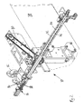
- the presentation of the Fig. 2 shows a drop former 70 according to a first embodiment of the invention in more detail.
- the drop former 70 has a rotating, perforated outer drum 72, within which a feed channel 74 and a nozzle bar 76 are arranged.
- the nozzle bar 76 abuts against an inner wall of the perforated outer drum 72 and is also opposite to a steel strip 78, which is moved under the drop former 70 therethrough.
- Liquid to be dripped passes through the feed channel 74 to the nozzle bar 76 and is pressed from the nozzle bar 76 through the openings of the rotating outer drum 72.
- the liquid in the form of drops has passed through the openings of the rotating outer drum 72, they are deposited on the steel strip 78.
- the deposited drops solidify during transport on the steel strip 78 to lozenges and can be removed at the deflection.
- the drop former 70 and in particular the inlet channel 74 is heated, wherein in the illustration of Fig. 2 for reasons of clarity, suitable heating devices are not shown.
- the urea melt passes through the heated pipe 82 into the feed channel and that is the urea melt in the region of a in the representation of Fig. 2 left end of the feed channel 74 introduced into this.
- a liquid additive is introduced via a pipe 84 into the supply line 74.
- an ultrasonic oscillator 86 is provided at this end of the feed channel 74, at which the urea melt pipe 82 and the liquid additive pipe 84 open.
- the ultrasonic oscillator 86 has a vibrating rod 88 which extends concentrically into the feed channel 74, so that an annular gap is formed between an inner wall of the feed channel 74 at this end and the outer wall of the oscillating rod 88.
- Both the urea melt and the liquid additive must pass through this annular gap in order to get into the further course of the feed channel 74 and especially to the nozzle bar 76. While the urea melt and the liquid additive flow through this annular gap, they are acted upon by ultrasonic waves. As a result, both the urea melt and the liquid additive are atomized or atomized by means of the ultrasonic waves into the smallest particles, with these smallest particles then mixing homogeneously.
- the vibrating rod 88 of the ultrasonic vibrator 86 protrudes, for example about 10 cm into the front end of the feed channel 74, oscillates at a frequency of about 24 kHz and has a power of about 400 W.
- a titanium sonotrode can be used, for example, has a diameter of 22 mm and which is inserted into the feed channel with a diameter of 30 mm. The width of the annular gap is consequently 4 mm.
- the presentation of the Fig. 3 shows another embodiment of a drop former 90 according to the invention.
- the drop former 90 also has the perforated, rotating outer drum 72, which is rotated by means of the chain 80 and which is arranged above the steel strip 78.
- the liquid to be dripped passes through the feed channel 74 to the nozzle bar 76 and then, as already explained, through the openings of the rotating outer drum 72 on the steel strip 78th Die Tropfenformer 90 der Fig. 3 is largely identical to the drop former 70 of Fig.2 and only the differences to the drop former 70 will be explained in more detail.
- the drop former 90 has a stirring device in the form of a helix 92 extending over the entire length of the feed channel 74.
- the coil is driven at one end by a motor 94 and ensures that the liquid in the feed channel 74 is kept in motion until it exits through the nozzle bar 76.
- a stirring device is particularly advantageous when suspensions are to be dripped, for example a mixture of a urea melt with another substance, for example ammonium sulfate, which optionally also has particles with a particle size of less than 250 microns.
- the helix 92 which keeps the mixture to be dripped constantly in motion, can prevent the particles, for example, following gravity, settle.
- a mixture of the urea melt and the solid additive, for example, ammonium sulfate according to the two-stage grinding and mixing method, which is based on the Fig. 1 was prepared.
- the presentation of the Fig. 4 shows a further embodiment of a drop former 100, which is very similar to the drop former 90 of Fig. 3 is constructed and differs only in the design of the helix. While the coil 92 of the Fig. 3 forms a three-dimensionally shaped helix, a helix 102 of the drop former 100 is formed as a wound metal band. It is in the representation of Fig. 4 to recognize that the coil 102 consists of a twisted around its longitudinal axis sheet metal strip. That in the presentation of the Fig. 4 right end of this metal strip is extended with a rod 104 and connected to a drive motor 106 shown only in sections.
- An output shaft of the drive motor 106 and a central longitudinal axis of the coil 102, in which the rod 104 is located, are aligned with each other. Good to see in the presentation of Fig. 4 also an orifice 108 of the heated pipe 82 for the urea melt.
- a pipe 84 is used to supply a liquid additive, wherein the pipe 84 opens only in the region of the beginning of the coil 102 in the feed channel 74.
- the helix 102 is provided with a plurality of spacers 112.
- the spacers 112 are each formed as protruding from the helix perpendicular plastic bolts with rounded free ends. The free, rounded ends of these plastic bolts are supported on an inner wall of the feed channel 74 and thereby ensure that the longitudinal edges 110 of the coil 102 are indeed performed at a small distance from the inner wall of the feed channel 74, but they do not touch.
- two opposing spacers are provided on different sides of the strip of material, which forms the coil 102 in each case.
- a plurality of spacers are provided, and advantageously the spacers 112 each seen in the longitudinal direction of the coil 102 so far apart that they are aligned perpendicular to each other.
- the coil 102 is followed by a further spacer 112 on a first spacer 112. In this way, the coil can be guided reliably in the supply channel 74.
- Fig. 4 can be seen further, only two spacers 112 can be seen.
- the drive torque is applied via the rod 104, and therefore a comparatively large deformation or twisting of the coil 102 in this region is to be expected.
- the helix 102 thus tends more to swerve laterally, so that two spacers 112 are provided at a short distance offset by 90 ° to each other.
Landscapes
- Chemical & Material Sciences (AREA)
- Organic Chemistry (AREA)
- Chemical Kinetics & Catalysis (AREA)
- Inorganic Chemistry (AREA)
- Life Sciences & Earth Sciences (AREA)
- Pest Control & Pesticides (AREA)
- Fertilizers (AREA)
- Glanulating (AREA)
Priority Applications (1)
| Application Number | Priority Date | Filing Date | Title |
|---|---|---|---|
| PL08860124T PL2229348T3 (pl) | 2007-12-11 | 2008-12-03 | Sposób i generator kropel do wytwarzania pastylek jak również sposób do wytwarzania nawozu zawierającego siarkę |
Applications Claiming Priority (2)
| Application Number | Priority Date | Filing Date | Title |
|---|---|---|---|
| DE102007061408A DE102007061408A1 (de) | 2007-12-11 | 2007-12-11 | Verfahren und Tropfenformer zum Herstellen von Pastillen sowie Verfahren zum Herstellen eines schwefelhaltigen Düngers |
| PCT/EP2008/010222 WO2009074250A2 (de) | 2007-12-11 | 2008-12-03 | Verfahren und tropfenformer zum herstellen von pastillen sowie verfahren zum herstellen eines schwefelhaltigen düngers |
Publications (2)
| Publication Number | Publication Date |
|---|---|
| EP2229348A2 EP2229348A2 (de) | 2010-09-22 |
| EP2229348B1 true EP2229348B1 (de) | 2015-03-11 |
Family
ID=40637719
Family Applications (1)
| Application Number | Title | Priority Date | Filing Date |
|---|---|---|---|
| EP08860124.0A Active EP2229348B1 (de) | 2007-12-11 | 2008-12-03 | Verfahren und tropfenformer zum herstellen von pastillen sowie verfahren zum herstellen eines schwefelhaltigen düngers |
Country Status (7)
| Country | Link |
|---|---|
| US (1) | US8349229B2 (pt) |
| EP (1) | EP2229348B1 (pt) |
| BR (1) | BRPI0820655B1 (pt) |
| DE (1) | DE102007061408A1 (pt) |
| EA (1) | EA018093B1 (pt) |
| PL (1) | PL2229348T3 (pt) |
| WO (1) | WO2009074250A2 (pt) |
Families Citing this family (21)
| Publication number | Priority date | Publication date | Assignee | Title |
|---|---|---|---|---|
| DE102009039125A1 (de) | 2009-08-27 | 2011-03-03 | Baerlocher Gmbh | Verfahren zur Konfektionierung von Stabilisator-Schmelzen, danach hergestellte Formkörper und deren Verwendung |
| DE102010032021B4 (de) * | 2010-07-16 | 2016-09-29 | Sandvik Materials Technology Deutschland Gmbh | Verfahren zum Herstellen von Ammoniumnitrat enthaltenden Partikeln |
| US8329072B2 (en) | 2010-11-24 | 2012-12-11 | Brimrock International Inc. | Method and system for generating sulfur seeds and granules |
| WO2012095864A2 (en) * | 2011-01-14 | 2012-07-19 | Innovative Environmental Technologies Pvt. Ltd. | A plant nutrient composition and a process for preparing the same |
| US9102081B2 (en) * | 2011-11-21 | 2015-08-11 | Dr. Hielscher Gmbh | Method and apparatus for generating particles |
| CN102731171B (zh) * | 2012-06-05 | 2014-02-19 | 四川美丰化工股份有限公司 | 固体尿素熔融喷浆造粒系统 |
| HUE044478T2 (hu) | 2012-07-09 | 2019-10-28 | Shell Int Research | Eljárás elemi kén részecskék emulziójának elõállítására |
| ITMI20121649A1 (it) * | 2012-10-02 | 2014-04-03 | Sbs Steel Belt Systems S R L | Processo per la produzione di fertilizzante in pastiglie e fertilizzante in pastiglie cosi¿ prodotto |
| ITMI20121648A1 (it) * | 2012-10-02 | 2014-04-03 | Sbs Steel Belt Systems S R L | Processo ed apparecchiatura per la produzione di fertilizzante in pastiglie |
| EP3092210A1 (en) * | 2014-01-09 | 2016-11-16 | Shell Internationale Research Maatschappij B.V. | Process for preparing a urea-sulphur fertiliser |
| CN106470961B (zh) | 2014-07-28 | 2020-01-10 | 国际壳牌研究有限公司 | 制备尿素-硫肥料的方法 |
| US9763860B2 (en) | 2014-11-04 | 2017-09-19 | The Procter & Gamble Company | Apparatus and process for forming particles |
| DE102015212353B3 (de) * | 2015-07-01 | 2016-07-07 | Sandvik Materials Technology Deutschland Gmbh | Vorrichtung und Verfahren zum Vertropfen eines fließfähigen Produkts |
| ES2926955T3 (es) | 2015-07-07 | 2022-10-31 | Yara Int Asa | Método de fabricación de un material particulado a base de urea que contiene azufre elemental |
| DE202015105252U1 (de) * | 2015-10-05 | 2015-11-23 | Lagerhaus Eichinger GmbH & Co. KG | Düngemittel |
| US10465048B2 (en) | 2017-01-09 | 2019-11-05 | The Procter & Gamble Company | Apparatus and process for forming particles |
| DE102018005069A1 (de) | 2018-06-26 | 2020-01-02 | Skw Stickstoffwerke Piesteritz Gmbh | Verfahren zur Herstellung von harnstoffbasierten Düngemitteln mit elementaren Schwefel und Produkte davon |
| CN109723618A (zh) * | 2018-12-28 | 2019-05-07 | 四川金象赛瑞化工股份有限公司 | 尿素泵的在线备用方法、应用和系统 |
| CN111558332A (zh) * | 2020-03-27 | 2020-08-21 | 浙江三圣科技有限公司 | 一种大颗粒复合肥造粒成型装置 |
| EP4001246A1 (en) | 2020-11-20 | 2022-05-25 | Clariant Produkte (Deutschland) GmbH | Vinasse containing fertilizer |
| WO2025007163A1 (ru) * | 2023-06-26 | 2025-01-02 | Общество С Ограниченной Ответственностью "Сульфотек'' | Способ получения карбамидно-серных удобрений |
Family Cites Families (28)
| Publication number | Priority date | Publication date | Assignee | Title |
|---|---|---|---|---|
| BE659404A (pt) * | 1964-02-12 | 1965-05-28 | ||
| GB1389821A (en) * | 1971-05-08 | 1975-04-09 | Fisons Ltd | Prilling |
| CA1144771A (en) * | 1980-12-24 | 1983-04-19 | Cominco Ltd. | Manufacture of urea sulfur fertilizer |
| US4383855A (en) * | 1981-04-01 | 1983-05-17 | The United States Of America As Represented By The United States Department Of Energy | Cermets and method for making same |
| DE3124200C2 (de) * | 1981-06-19 | 1986-03-27 | Santrade Ltd., Luzern/Lucerne | Verfahren zur Herstellung von Schwefel in Granulatform |
| DE4032683C3 (de) * | 1990-10-15 | 1996-06-13 | Santrade Ltd | Vorrichtung zur Bildung von Tropfen |
| DE4322629C1 (de) * | 1993-07-07 | 1994-08-18 | Santrade Ltd | Verfahren zur Herstellung von Granulat aus geschmolzenen Produkten |
| DE4332952C1 (de) * | 1993-09-28 | 1994-06-16 | Santrade Ltd | Vorrichtung zur Herstellung von Granulat |
| US5326164A (en) * | 1993-10-28 | 1994-07-05 | Logan James R | Fluid mixing device |
| US5439288A (en) | 1994-02-01 | 1995-08-08 | General Signal Corporation | Automated small volume recirculator for particle analysis |
| DE4440875A1 (de) * | 1994-11-16 | 1996-06-05 | Santrade Ltd | Vorrichtung zur Herstellung von Pastillen |
| US5858957A (en) * | 1995-01-26 | 1999-01-12 | The Procter & Gamble Company | Process for the manufacture of granular detergent compositions comprising nonionic surfactant |
| US5571303B1 (en) | 1995-03-06 | 2000-10-17 | Cominco Ltd | Sulfur-based fertilizer and process for production thereof |
| DE19527067C1 (de) * | 1995-07-25 | 1996-12-05 | Santrade Ltd | Vorrichtung und Verfahren zum Konditionieren einer Flüssigkeit |
| US5782951A (en) * | 1997-02-20 | 1998-07-21 | Western Industrial Clay Products, Inc. | Particulate urea with finely divided inorganic material incorporated for hardness nonfriability and anti-caking |
| DE19758450C2 (de) * | 1997-09-18 | 2000-04-06 | Santrade Ltd | Vorrichtung zur Herstellung von Granulat |
| DE69924169T2 (de) * | 1998-02-27 | 2006-02-02 | Sandvik Intellectual Property Hb | Verfahren und Vorrichtung zum tropfenförmigen Aufbringen fliessfähiger Massen auf ein Transportband |
| DE19809242A1 (de) | 1998-03-05 | 1999-09-09 | Basf Ag | Verfahren zur Herstellung von festen, sphärischen Formkörpern, enthaltend pharmazeutische Wirkstoffe in einer Bindemittelmatrix |
| DE19826570C2 (de) * | 1998-06-15 | 2002-10-31 | Piesteritz Stickstoff | Verfahren zur Herstellung von Harnstoff und Ammonsulfat enthaltenden Düngemittel-Granulaten |
| ES2187220B2 (es) | 1999-07-13 | 2003-12-01 | Univ Alicante | Metodo y equipo para la determinacion del equilibrio liquido-liquido-vapor isobarico en sistemas heterogeneos. |
| EP1195365A1 (de) | 2000-09-21 | 2002-04-10 | Agra Dünger GmbH | Verfahren zur Herstellung von Methylenharnstoff-Polymeren |
| DE10138333C2 (de) | 2001-07-27 | 2003-08-28 | Santrade Ltd | Vorrichtung zum Auspressen fließfähiger Substanzen |
| US20030047224A1 (en) | 2001-09-07 | 2003-03-13 | Bernard Cohen | Apparatus and method to improve the flow of viscous liquids |
| US6716015B2 (en) * | 2001-11-26 | 2004-04-06 | Enersul, Inc. | Distribution system for a pastillation machine |
| DE10306688B3 (de) * | 2003-02-11 | 2004-11-11 | Santrade Ltd. | Vorrichtung zur Herstellung von Granulat |
| DE102004009709B4 (de) * | 2004-02-27 | 2009-06-25 | Cognis Ip Management Gmbh | Verfahren zum Pastillieren von schmelzbarem Produkt |
| JP5649781B2 (ja) | 2005-04-18 | 2015-01-07 | スタミカーボン ビー. ブイ. | 尿素含有粒子の製造方法 |
| DE102005054462B4 (de) * | 2005-11-08 | 2009-08-06 | Santrade Ltd. | Verfahren zur Bandkonditionierung bei Pastillieranlagen |
-
2007
- 2007-12-11 DE DE102007061408A patent/DE102007061408A1/de not_active Ceased
-
2008
- 2008-12-03 WO PCT/EP2008/010222 patent/WO2009074250A2/de not_active Ceased
- 2008-12-03 PL PL08860124T patent/PL2229348T3/pl unknown
- 2008-12-03 EP EP08860124.0A patent/EP2229348B1/de active Active
- 2008-12-03 BR BRPI0820655A patent/BRPI0820655B1/pt active IP Right Grant
- 2008-12-03 US US12/734,940 patent/US8349229B2/en not_active Expired - Fee Related
- 2008-12-03 EA EA201070693A patent/EA018093B1/ru not_active IP Right Cessation
Also Published As
| Publication number | Publication date |
|---|---|
| EA018093B1 (ru) | 2013-05-30 |
| BRPI0820655A2 (pt) | 2015-06-16 |
| EP2229348A2 (de) | 2010-09-22 |
| WO2009074250A2 (de) | 2009-06-18 |
| PL2229348T3 (pl) | 2015-08-31 |
| DE102007061408A1 (de) | 2009-06-18 |
| BRPI0820655B1 (pt) | 2018-12-11 |
| EA201070693A1 (ru) | 2010-12-30 |
| US20100288005A1 (en) | 2010-11-18 |
| US8349229B2 (en) | 2013-01-08 |
| WO2009074250A3 (de) | 2009-11-05 |
Similar Documents
| Publication | Publication Date | Title |
|---|---|---|
| EP2229348B1 (de) | Verfahren und tropfenformer zum herstellen von pastillen sowie verfahren zum herstellen eines schwefelhaltigen düngers | |
| DE4400330C2 (de) | Verfahren zum Herstellen eines geschäumten Produktes oder Schaumstoffmaterials aus nichtmodifizierter Stärke sowie Einrichtung zum Durchführen des Verfahrens | |
| DE10010176B4 (de) | Verfahren und Vorrichtung zur Herstellung eines mit Additiv behandelten Filterkabels | |
| EP0814133B1 (de) | Verfahren zur kontinuierlichen Trockengranulation von Pulverruss | |
| WO1999033554A1 (de) | Vorrichtung zum mischen und anschliessendem versprühen von flüssigkeiten | |
| EP2922671B1 (de) | Fallschachtanordnung mit zweifacher reinigungseinrichtung, insbesondere für eine vorrichtung zur beleimung von partikeln im zuge der herstellung von werkstoffplatten | |
| DE3143895A1 (de) | Verfahren und vorrichtung zum beleimen von teilchenfoermigem gut, insbesondere von spaenen | |
| EP3423179B1 (de) | Vorrichtung, anlage und verfahren zum zumischen wenigstens eines ersten stoffs und eines zweiten stoffs zu einem grundstoff zur bildung einer mischung | |
| DE112006000001B4 (de) | Kontaktfilterblock sowie Verfahren und Vorrichtung zum Herstellen von Konstruktionselementen eines Kontaktfilterblocks | |
| WO2013071327A2 (de) | Durchlaufmischer sowie vorrichtung und verfahren zur herstellung von kunststein mit hilfe des durchlaufmischers | |
| EP1288600B1 (de) | Vorrichtung zur Trocknung eines rieselfähigen Stoffs im Gegenstrom mit einem gasförmigen Fluid | |
| DE102020103912A1 (de) | Transportvorrichtung zum Befördern von Kunststoffpartikeln sowie Verfahren zum Zerkleinern von Kunststoffpartikeln | |
| DE1507892C3 (de) | Vorrichtung zum Benetzen pulverförmiger Stoffe mit einer Flüssigkeit | |
| EP0086426A2 (de) | Verfahren und Vorrichtung zur Herstellung von Kunststoff-Fäden | |
| EP3772502A1 (de) | Verfahren zur herstellung von düngemittelgranulat | |
| DE1729196A1 (de) | Verfahren und Vorrichtung zum Herstellen von mit einem Fuellmaterial versehenen Stangen oder Rohren | |
| DE20119055U1 (de) | Vorrichtung zum Hinzufügen von Bindemittel zu einem Fluss von losem hölzernen Material | |
| DE102004018436A1 (de) | Verfahren sowie Vorrichtung zur Bereitstellung eines Polymer-Granulats | |
| DE2248851B1 (de) | Vorrichtung zur Herstellung einer Suspension aus Wasser und geloeschtem Kalk | |
| WO2018197302A1 (de) | Granulationsvorrichtung | |
| WO2002002482A1 (de) | Verfahren zur herstellung eines düngemittels | |
| DE102023119050A1 (de) | Unterwasser-Granuliervorrichtung und -verfahren | |
| EP0955141A2 (de) | Verfahren und Vorrichtung für die Bereitstellung von pastösen Baustoffen, insbesondere Mörtel auf Baustellen | |
| EP0036985A1 (de) | Einrichtung zur Erzeugung eines Gemisches aus mindestens einem zerdrückbaren stückigen Feststoff und mindestens einem flüssigen Bestandteil | |
| DE19755578A1 (de) | Verfahren und Vorrichtung zur Herstellung von anreagierten Bindepartikeln aus Ausgangskomponenten unterschiedlicher Rezepturen |
Legal Events
| Date | Code | Title | Description |
|---|---|---|---|
| PUAI | Public reference made under article 153(3) epc to a published international application that has entered the european phase |
Free format text: ORIGINAL CODE: 0009012 |
|
| 17P | Request for examination filed |
Effective date: 20100705 |
|
| AK | Designated contracting states |
Kind code of ref document: A2 Designated state(s): AT BE BG CH CY CZ DE DK EE ES FI FR GB GR HR HU IE IS IT LI LT LU LV MC MT NL NO PL PT RO SE SI SK TR |
|
| AX | Request for extension of the european patent |
Extension state: AL BA MK RS |
|
| RIN1 | Information on inventor provided before grant (corrected) |
Inventor name: KLEINHANS, MATTHIAS Inventor name: BAEDER, ALBERT Inventor name: SCHROMM, HANS-KURT |
|
| DAX | Request for extension of the european patent (deleted) | ||
| RIN1 | Information on inventor provided before grant (corrected) |
Inventor name: BAEDER, ALBERT Inventor name: KLEINHANS, MATTHIAS Inventor name: SCHROMM, HANS-KURT |
|
| 17Q | First examination report despatched |
Effective date: 20111014 |
|
| GRAP | Despatch of communication of intention to grant a patent |
Free format text: ORIGINAL CODE: EPIDOSNIGR1 |
|
| INTG | Intention to grant announced |
Effective date: 20141008 |
|
| GRAS | Grant fee paid |
Free format text: ORIGINAL CODE: EPIDOSNIGR3 |
|
| GRAA | (expected) grant |
Free format text: ORIGINAL CODE: 0009210 |
|
| AK | Designated contracting states |
Kind code of ref document: B1 Designated state(s): AT BE BG CH CY CZ DE DK EE ES FI FR GB GR HR HU IE IS IT LI LT LU LV MC MT NL NO PL PT RO SE SI SK TR |
|
| REG | Reference to a national code |
Ref country code: GB Ref legal event code: FG4D Free format text: NOT ENGLISH |
|
| REG | Reference to a national code |
Ref country code: CH Ref legal event code: EP |
|
| REG | Reference to a national code |
Ref country code: RO Ref legal event code: EPE |
|
| REG | Reference to a national code |
Ref country code: IE Ref legal event code: FG4D Free format text: LANGUAGE OF EP DOCUMENT: GERMAN |
|
| REG | Reference to a national code |
Ref country code: AT Ref legal event code: REF Ref document number: 715241 Country of ref document: AT Kind code of ref document: T Effective date: 20150415 |
|
| REG | Reference to a national code |
Ref country code: DE Ref legal event code: R096 Ref document number: 502008012772 Country of ref document: DE Effective date: 20150423 |
|
| REG | Reference to a national code |
Ref country code: NL Ref legal event code: T3 |
|
| PG25 | Lapsed in a contracting state [announced via postgrant information from national office to epo] |
Ref country code: SE Free format text: LAPSE BECAUSE OF FAILURE TO SUBMIT A TRANSLATION OF THE DESCRIPTION OR TO PAY THE FEE WITHIN THE PRESCRIBED TIME-LIMIT Effective date: 20150311 Ref country code: FI Free format text: LAPSE BECAUSE OF FAILURE TO SUBMIT A TRANSLATION OF THE DESCRIPTION OR TO PAY THE FEE WITHIN THE PRESCRIBED TIME-LIMIT Effective date: 20150311 Ref country code: NO Free format text: LAPSE BECAUSE OF FAILURE TO SUBMIT A TRANSLATION OF THE DESCRIPTION OR TO PAY THE FEE WITHIN THE PRESCRIBED TIME-LIMIT Effective date: 20150611 Ref country code: HR Free format text: LAPSE BECAUSE OF FAILURE TO SUBMIT A TRANSLATION OF THE DESCRIPTION OR TO PAY THE FEE WITHIN THE PRESCRIBED TIME-LIMIT Effective date: 20150311 Ref country code: ES Free format text: LAPSE BECAUSE OF FAILURE TO SUBMIT A TRANSLATION OF THE DESCRIPTION OR TO PAY THE FEE WITHIN THE PRESCRIBED TIME-LIMIT Effective date: 20150311 Ref country code: LT Free format text: LAPSE BECAUSE OF FAILURE TO SUBMIT A TRANSLATION OF THE DESCRIPTION OR TO PAY THE FEE WITHIN THE PRESCRIBED TIME-LIMIT Effective date: 20150311 |
|
| REG | Reference to a national code |
Ref country code: LT Ref legal event code: MG4D |
|
| PG25 | Lapsed in a contracting state [announced via postgrant information from national office to epo] |
Ref country code: GR Free format text: LAPSE BECAUSE OF FAILURE TO SUBMIT A TRANSLATION OF THE DESCRIPTION OR TO PAY THE FEE WITHIN THE PRESCRIBED TIME-LIMIT Effective date: 20150612 Ref country code: LV Free format text: LAPSE BECAUSE OF FAILURE TO SUBMIT A TRANSLATION OF THE DESCRIPTION OR TO PAY THE FEE WITHIN THE PRESCRIBED TIME-LIMIT Effective date: 20150311 |
|
| REG | Reference to a national code |
Ref country code: PL Ref legal event code: T3 |
|
| PG25 | Lapsed in a contracting state [announced via postgrant information from national office to epo] |
Ref country code: SK Free format text: LAPSE BECAUSE OF FAILURE TO SUBMIT A TRANSLATION OF THE DESCRIPTION OR TO PAY THE FEE WITHIN THE PRESCRIBED TIME-LIMIT Effective date: 20150311 Ref country code: PT Free format text: LAPSE BECAUSE OF FAILURE TO SUBMIT A TRANSLATION OF THE DESCRIPTION OR TO PAY THE FEE WITHIN THE PRESCRIBED TIME-LIMIT Effective date: 20150713 Ref country code: CZ Free format text: LAPSE BECAUSE OF FAILURE TO SUBMIT A TRANSLATION OF THE DESCRIPTION OR TO PAY THE FEE WITHIN THE PRESCRIBED TIME-LIMIT Effective date: 20150311 Ref country code: EE Free format text: LAPSE BECAUSE OF FAILURE TO SUBMIT A TRANSLATION OF THE DESCRIPTION OR TO PAY THE FEE WITHIN THE PRESCRIBED TIME-LIMIT Effective date: 20150311 |
|
| PG25 | Lapsed in a contracting state [announced via postgrant information from national office to epo] |
Ref country code: IS Free format text: LAPSE BECAUSE OF FAILURE TO SUBMIT A TRANSLATION OF THE DESCRIPTION OR TO PAY THE FEE WITHIN THE PRESCRIBED TIME-LIMIT Effective date: 20150711 |
|
| REG | Reference to a national code |
Ref country code: DE Ref legal event code: R097 Ref document number: 502008012772 Country of ref document: DE |
|
| PLBE | No opposition filed within time limit |
Free format text: ORIGINAL CODE: 0009261 |
|
| STAA | Information on the status of an ep patent application or granted ep patent |
Free format text: STATUS: NO OPPOSITION FILED WITHIN TIME LIMIT |
|
| PG25 | Lapsed in a contracting state [announced via postgrant information from national office to epo] |
Ref country code: DK Free format text: LAPSE BECAUSE OF FAILURE TO SUBMIT A TRANSLATION OF THE DESCRIPTION OR TO PAY THE FEE WITHIN THE PRESCRIBED TIME-LIMIT Effective date: 20150311 |
|
| 26N | No opposition filed |
Effective date: 20151214 |
|
| PG25 | Lapsed in a contracting state [announced via postgrant information from national office to epo] |
Ref country code: SI Free format text: LAPSE BECAUSE OF FAILURE TO SUBMIT A TRANSLATION OF THE DESCRIPTION OR TO PAY THE FEE WITHIN THE PRESCRIBED TIME-LIMIT Effective date: 20150311 |
|
| PG25 | Lapsed in a contracting state [announced via postgrant information from national office to epo] |
Ref country code: BE Free format text: LAPSE BECAUSE OF NON-PAYMENT OF DUE FEES Effective date: 20151231 |
|
| PG25 | Lapsed in a contracting state [announced via postgrant information from national office to epo] |
Ref country code: LU Free format text: LAPSE BECAUSE OF FAILURE TO SUBMIT A TRANSLATION OF THE DESCRIPTION OR TO PAY THE FEE WITHIN THE PRESCRIBED TIME-LIMIT Effective date: 20151203 Ref country code: MC Free format text: LAPSE BECAUSE OF FAILURE TO SUBMIT A TRANSLATION OF THE DESCRIPTION OR TO PAY THE FEE WITHIN THE PRESCRIBED TIME-LIMIT Effective date: 20150311 |
|
| REG | Reference to a national code |
Ref country code: CH Ref legal event code: PL |
|
| GBPC | Gb: european patent ceased through non-payment of renewal fee |
Effective date: 20151203 |
|
| REG | Reference to a national code |
Ref country code: IE Ref legal event code: MM4A |
|
| REG | Reference to a national code |
Ref country code: FR Ref legal event code: ST Effective date: 20160831 |
|
| PG25 | Lapsed in a contracting state [announced via postgrant information from national office to epo] |
Ref country code: GB Free format text: LAPSE BECAUSE OF NON-PAYMENT OF DUE FEES Effective date: 20151203 Ref country code: IE Free format text: LAPSE BECAUSE OF NON-PAYMENT OF DUE FEES Effective date: 20151203 Ref country code: CH Free format text: LAPSE BECAUSE OF NON-PAYMENT OF DUE FEES Effective date: 20151231 Ref country code: LI Free format text: LAPSE BECAUSE OF NON-PAYMENT OF DUE FEES Effective date: 20151231 |
|
| PG25 | Lapsed in a contracting state [announced via postgrant information from national office to epo] |
Ref country code: FR Free format text: LAPSE BECAUSE OF NON-PAYMENT OF DUE FEES Effective date: 20151231 |
|
| PG25 | Lapsed in a contracting state [announced via postgrant information from national office to epo] |
Ref country code: BG Free format text: LAPSE BECAUSE OF FAILURE TO SUBMIT A TRANSLATION OF THE DESCRIPTION OR TO PAY THE FEE WITHIN THE PRESCRIBED TIME-LIMIT Effective date: 20150311 Ref country code: HU Free format text: LAPSE BECAUSE OF FAILURE TO SUBMIT A TRANSLATION OF THE DESCRIPTION OR TO PAY THE FEE WITHIN THE PRESCRIBED TIME-LIMIT; INVALID AB INITIO Effective date: 20081203 |
|
| PG25 | Lapsed in a contracting state [announced via postgrant information from national office to epo] |
Ref country code: CY Free format text: LAPSE BECAUSE OF FAILURE TO SUBMIT A TRANSLATION OF THE DESCRIPTION OR TO PAY THE FEE WITHIN THE PRESCRIBED TIME-LIMIT Effective date: 20150311 |
|
| PG25 | Lapsed in a contracting state [announced via postgrant information from national office to epo] |
Ref country code: MT Free format text: LAPSE BECAUSE OF FAILURE TO SUBMIT A TRANSLATION OF THE DESCRIPTION OR TO PAY THE FEE WITHIN THE PRESCRIBED TIME-LIMIT Effective date: 20150311 Ref country code: TR Free format text: LAPSE BECAUSE OF FAILURE TO SUBMIT A TRANSLATION OF THE DESCRIPTION OR TO PAY THE FEE WITHIN THE PRESCRIBED TIME-LIMIT Effective date: 20150311 |
|
| REG | Reference to a national code |
Ref country code: DE Ref legal event code: R082 Ref document number: 502008012772 Country of ref document: DE Representative=s name: PATENTANWAELTE RUFF, WILHELM, BEIER, DAUSTER &, DE Ref country code: DE Ref legal event code: R081 Ref document number: 502008012772 Country of ref document: DE Owner name: SANDVIK SPS GMBH, DE Free format text: FORMER OWNER: SANDVIK MATERIALS TECHNOLOGY DEUTSCHLAND GMBH, 40549 DUESSELDORF, DE Ref country code: DE Ref legal event code: R081 Ref document number: 502008012772 Country of ref document: DE Owner name: IPCO GERMANY GMBH, DE Free format text: FORMER OWNER: SANDVIK MATERIALS TECHNOLOGY DEUTSCHLAND GMBH, 40549 DUESSELDORF, DE |
|
| REG | Reference to a national code |
Ref country code: DE Ref legal event code: R082 Ref document number: 502008012772 Country of ref document: DE Representative=s name: PATENTANWAELTE RUFF, WILHELM, BEIER, DAUSTER &, DE Ref country code: DE Ref legal event code: R081 Ref document number: 502008012772 Country of ref document: DE Owner name: IPCO GERMANY GMBH, DE Free format text: FORMER OWNER: SANDVIK SPS GMBH, 70736 FELLBACH, DE |
|
| REG | Reference to a national code |
Ref country code: AT Ref legal event code: PC Ref document number: 715241 Country of ref document: AT Kind code of ref document: T Owner name: IPCO GERMANY GMBH NIEDERLASSUNG SPS FELLBACH, DE Effective date: 20181129 |
|
| REG | Reference to a national code |
Ref country code: NL Ref legal event code: PD Owner name: IPCO GERMANY GMBH; DE Free format text: DETAILS ASSIGNMENT: CHANGE OF OWNER(S), ASSIGNMENT; FORMER OWNER NAME: SANDVIK MATERIALS TECHNOLOGY DEUTSCHLAND GMBH Effective date: 20181114 |
|
| PGFP | Annual fee paid to national office [announced via postgrant information from national office to epo] |
Ref country code: IT Payment date: 20211217 Year of fee payment: 14 |
|
| PGFP | Annual fee paid to national office [announced via postgrant information from national office to epo] |
Ref country code: RO Payment date: 20221125 Year of fee payment: 15 |
|
| PG25 | Lapsed in a contracting state [announced via postgrant information from national office to epo] |
Ref country code: IT Free format text: LAPSE BECAUSE OF NON-PAYMENT OF DUE FEES Effective date: 20221203 |
|
| PG25 | Lapsed in a contracting state [announced via postgrant information from national office to epo] |
Ref country code: RO Free format text: LAPSE BECAUSE OF NON-PAYMENT OF DUE FEES Effective date: 20231203 |
|
| PGFP | Annual fee paid to national office [announced via postgrant information from national office to epo] |
Ref country code: PL Payment date: 20241104 Year of fee payment: 17 |
|
| PGFP | Annual fee paid to national office [announced via postgrant information from national office to epo] |
Ref country code: DE Payment date: 20241218 Year of fee payment: 17 |
|
| PGFP | Annual fee paid to national office [announced via postgrant information from national office to epo] |
Ref country code: AT Payment date: 20251215 Year of fee payment: 18 |
|
| PGFP | Annual fee paid to national office [announced via postgrant information from national office to epo] |
Ref country code: NL Payment date: 20251217 Year of fee payment: 18 |