EP2226416B1 - Startdüse mit Schussfadenrückhaltemitteln für eine pneumatische Webmaschine - Google Patents
Startdüse mit Schussfadenrückhaltemitteln für eine pneumatische Webmaschine Download PDFInfo
- Publication number
- EP2226416B1 EP2226416B1 EP10155605.8A EP10155605A EP2226416B1 EP 2226416 B1 EP2226416 B1 EP 2226416B1 EP 10155605 A EP10155605 A EP 10155605A EP 2226416 B1 EP2226416 B1 EP 2226416B1
- Authority
- EP
- European Patent Office
- Prior art keywords
- nozzle
- bristles
- launch
- lance
- weft
- Prior art date
- Legal status (The legal status is an assumption and is not a legal conclusion. Google has not performed a legal analysis and makes no representation as to the accuracy of the status listed.)
- Active
Links
Images


Classifications
-
- D—TEXTILES; PAPER
- D03—WEAVING
- D03D—WOVEN FABRICS; METHODS OF WEAVING; LOOMS
- D03D47/00—Looms in which bulk supply of weft does not pass through shed, e.g. shuttleless looms, gripper shuttle looms, dummy shuttle looms
- D03D47/28—Looms in which bulk supply of weft does not pass through shed, e.g. shuttleless looms, gripper shuttle looms, dummy shuttle looms wherein the weft itself is projected into the shed
- D03D47/30—Looms in which bulk supply of weft does not pass through shed, e.g. shuttleless looms, gripper shuttle looms, dummy shuttle looms wherein the weft itself is projected into the shed by gas jet
- D03D47/3006—Construction of the nozzles
- D03D47/3013—Main nozzles
Definitions
- the present invention refers to an improved launch nozzle for a pneumatic weaving loom.
- weaving in a weaving loom requires that a series of crosswise wefts is inserted into a set of parallel warp yarns, opening said yarns scissor-wise, according to different and preset patterns, by means of the weaving machine. Upon each insertion, the weft is then beaten against the fabric being formed, by means of a reed device, and the cycle is repeated at very high speeds, up to 1.200-1.500 strikes per minute.
- weft insertion into the warp shed occurs according to various technologies.
- the weft is inserted using an air jet which blows the weft, through a suitable launch nozzle, at the entrance of the warp shed; along the warp shed additional relay nozzles are located with air jets which make the weft thread flies towards the shed exit, on the opposite side of the loom.
- Fig. 1 shows schematically the devices intended for weft insertion in a weaving loom.
- the weft thread comes out of a thread spool, runs on a drum pre-meter, enters a pre-nozzle and then a main nozzle. From said main nozzle, through a suitable control of the compressed air flow, the weft thread is inserted into the warp shed until it comes out from the opposite side. Once it is completely inserted, the weft thread is cut in correspondence of the entry side, so as to severe it from the spool and leave it inserted in the fabric: a new thread end is thus formed, which can be inserted again during the following cycle.
- This configuration is suited to a single weft thread and is repeated for the number of weft threads (different by colour, type, count, and so on) made simultaneously available on the same loom.
- the need exists to arrange the launch point of all weft threads (i.e. of all the nozzles) around a very small area. Therefore, on a practical level, at least the final launch device normally consists of a rather complex assembly which incorporates a plurality of lances with which the individual weft threads are associated.
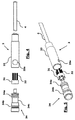
- Such a multiple, prior-art nozzle, able to handle up to four weft threads is illustrated in figs. 2 and 3 , in an assembled condition and in an exploded condition, respectively.
- a main block body 1 has a series of seats 1a with converging axes. Inside such seats there are inserted, on the entry side - i.e. on the upstream side with respect to the flow direction - a corresponding plurality of needles 2, i.e. devices configured to suitably channel the air flow together with the weft thread. On the exit side, within the seats 1a of the block body there are engaged base bodies 3 of rectilinear lances 4, which converge towards a head clamp 5 which keeps them with the open ends closely adjacent. Each lance 4 is substantially shaped as a hollow cannula, with a base body 3 having an enlarged diameter suitable for coupling with the seats of block body 1.
- a problem affecting this type of configuration is that of keeping the weft thread correctly inserted in the nozzles, i.e. of avoiding that the thread can come out upstream of the needle.
- the weft thread is kept taut and correctly inserted only by the dynamic air pressure; therefore, when it is cut at the end of the insertion, the elastic return of the fibre material may cause the free end to come up along the lance and come out behind the needle.
- the exit of the thread from the nozzle forces to stop the loom to be able to re-enter the thread, with inevitable productivity reduction, costs and possible fabric flaws.
- One provides to supply the nozzle block body with a series of (electric or, usually, pneumatic) actuators which are operative between the body of the lance and the needles with a gripping system apt to mechanically clamp the weft thread.
- FIG. 2 An exemplifying embodiment of this system of the prior art is shown precisely in figs. 2 and 3 .
- main block body 1 crosswise seats 10 are provided with which gripping devices 11 are engaged, said devices being variously controlled, for example by means of a pneumatic circuit.
- This mode is quite effective, because it allows to securely retain the weft thread and avoid the exit thereof on the upstream side of the nozzle.
- it is very expensive, because it provides the use of reliable actuators operating at a high frequency (as a matter of fact, the gripping system must release the weft thread during the launch and block it after cutting with a frequency equal to the number of insertions per minute, up to 25 Hz), as well as a drive chain synchronised with the main drive of the loom. This system also requires considerable maintenance.
- a second approach provides to use a continuous air jet within the lances (both during operation and with a stationary loom).
- the dynamic air pressure in addition to allowing the weft launch when it is released from the weft feeders, prevents it from being able to rise backwards when it is cut.
- EP 2014808 discloses a tubular element to be provided within an air-jet channel.
- the trailing edge of the tubular element is provided with a plurality of notches defining a plurality of corresponding projections.
- JP51124159 discloses a launch nozzle for a weft thread, comprising a conical ar-ray of flexible elements abuttig outside from the launch nozzle output opening, said flexible elements being able to retain the thread with their mutually contacting free ends.
- a weft thread launch nozzle according to the preamble of claim 1 is known from JP 2007 177341 A .
- the object of the present invention is hence to solve the above-mentioned problems, suggesting an innovative retaining system of the weft thread inside launch nozzles.
- a launch nozzle for a weft thread in a pneumatic weaving loom, of the type comprising at least one lance, which projects from a respective base body, provided with a through-hole in which it is possible to establish a flow of compressed air, wherein said base body has ciliated means inside, provided with a central gap for compressed air.
- the ciliated means are shaped as a tubular support wherefrom tufts of bristles project.
- ciliated means for a nozzle of a pneumatic weaving loom consisting of a tubular portion from the trailing edge of which a plurality of flexible needle means project, along the longitudinal tubular axis.
- the nozzle device according to the invention provides a configuration fully similar to the prior-art one, thereby hence remaining fully interchangeable in prior-art systems and weaving looms.
- a tubular support body 31 is provided inside the base body 3 of lances 4 , wherefrom flexible tufts or groups of bristles 32 depart.
- bristles 32 are distributed circumferentially on the circular trailing edge downstream of support body 31 and extend substantially along the longitudinal axis of the nozzle hole provided in body 3, i.e. along the longitudinal axis of lance 4.
- Tubular support 31 is preferably shaped as a ring of plastic material, with which bristles 32 are engaged, but it can also have other shapes. However, it is important that it comprises a central through-hole sufficiently wide not to obstruct the airflow path.
- Bristles 32 can be engaged with annular/tubular support 31 by means known per se, for example small metal anchors, or by injection molding techniques as used in the toothbrush field.
- bristles 32 are not perfectly parallel to the longitudinal axis of lance 4, but are slightly convergent towards one another, for example between 8° and 12°, preferably about 10°, so as to partly narrow the gap between the same.
- the tubular support body 31 provided with bristles 32 - which defines a ciliated body - is arranged inside lance body 3, with its internal hole having the same axis as the nozzle axis.
- each lance 4 is shaped as a hollow cylinder 33, integral with the cannula of lance 4, with which a cylindrical core 34 may be engaged, said core being provided with a longitudinal through-hole.
- Tubular support 31, provided with bristles 32, is inserted into hollow cylinder 33 and retained there in position - with the bristles projecting from support 31 in the air flow direction - by the subsequent insertion of cylindrical core 34.
- core 34 is preferably provided with one or more O-rings 34a, by which a steady coupling with hollow cylinder 33 is guaranteed.
- One or more further O-rings 34b are provided in the proximity of the rear end of core 34, to guarantee instead the coupling with seat 1a in the main block body 1.
- Core 34 further has a recessed portion 34c with which a clamp element (not shown) is intended to engage, which tightens lance body 3 on block body 1: for such purpose, hollow cylinder 33 is provided with a hole 33a which grants access to underlying recessed portion 34c, once core 34 has been inserted into cylinder 33.
- the presence of the bristles is an effective tool to avoid an upstream movement of the weft thread, once the air flow has been interrupted.
- they define - seen in the upstream direction - a plurality of spread tips on which the thread tends to get easily entangled.
- weft yarn entangling is obtained also upon elastic deformation of the bristles (which are bent compared to their original rectilinear shape); this results in an easy disentangling effect as soon as the regular air flow is established, after the beating phase of the loom: in fact, the air flow straightens the bristles back up into their rectilinear shape to easily free the weft yarn.
- the simplicity and compactness of the proposed ciliated means makes the device of the invention interchangeable with any existing multiple nozzle.
- the lance provided with ciliated means according to the invention can replace any existing lance, regardless of the retaining system previously used, without having to change other components.
- the element defined as ciliated body be provided with bristles consisting of groups of flexible single threads.
- it may comprise thin flexible laminas, small metal needles or flexible cilia; again, the entire brush body 31, 32 may be in a single body shaped as a bottomless basket, with slightly conical walls defined by a small net.
- any ciliated means which does not obstruct the air flow proceeding downstream, but which defines a plurality of entangling flexible needles proceeding upstream falls within the inventive principle set forth above (in order not to introduce important load losses, nor significant chafing against the weft threads during the launch phase).
Landscapes
- Engineering & Computer Science (AREA)
- Textile Engineering (AREA)
- Looms (AREA)
- Treatment Of Fiber Materials (AREA)
- Spinning Or Twisting Of Yarns (AREA)
Claims (8)
- Startdüse für Schussfaden in einer pneumatischen Webmaschine, der Bauart umfassend zumindest eine Lanze (4), die sich von einem entsprechenden Grundkörper (3) erstreckt, versehen mit einer Durchgangsöffnung, durch die eine Druckluftströmung erzeugt wird, und weiter umfassend flexible Zilienmittel, die in der Luftströmungsrichtung vorstehen, dadurch gekennzeichnet, dass die flexiblen Zilienmittel (31, 32) innerhalb des Grundkörpers (3) eingefügt sind und mit einem zentralen Spalt versehen sind, durch den die genannte Druckluftströmung strömt.
- Startdüse nach Anspruch 1, dadurch gekennzeichnet, dass der genannte Grundkörper (3) der Lanze (4) aus einem hohlen Zylinder (33) besteht, in den ein zylindrischer Kern (34) eingesetzt werden kann, wobei der Kern mit einer longitudinalen Durchgangsöffnung versehen ist, wobei die flexiblen Zilienmittel zwischen den genannten Kern (34) und dem hohlen Zylinder (33) angeordnet sind.
- Düse nach Anspruch 1 oder 3, dadurch gekennzeichnet, dass die flexiblen Zilienmittel als rohrförmiger, mit Borsten (32) versehener Träger (31) ausgebildet ist.
- Düse nach Anspruch 3, dadurch gekennzeichnet, dass die genannten Borsten (32) von einer Vorderkante stromab des genannten rohrförmigen Trägers (31) entlang dessen Längsachse vorstehen.
- Düse nach Anspruch 4, dadurch gekennzeichnet, dass die genannten Borsten (32) zueinander konvergieren.
- Startdüse nach einem der vorangehenden Ansprüche, dadurch gekennzeichnet, dass der genannte Grundkörper (3) der Lanze (4) mit einem Austrittssitz eines Hauptblockkörpers (1), der auf der gegenüberliegenden Seite des Austrittssitzes mit einem Eintrittssitz versehen ist, mit dem eine Nadel (2) in Eingriff steht, in Eingriff steht.
- Startdüse nach Anspruch 6, dadurch gekennzeichnet, dass der genannte Hauptblockkörper (1) eine Anzahl von Lanzen (4) aufweist, die mit ihren jeweiligen offenen Enden zueinander konvergieren.
- Pneumatische Webmaschine, dadurch gekennzeichnet, dass sie eine Düse und flexible Zilienmittel aufweist, gemäß einem der vorangehenden Ansprüche.
Applications Claiming Priority (1)
| Application Number | Priority Date | Filing Date | Title |
|---|---|---|---|
| IT000336A ITMI20090336A1 (it) | 2009-03-06 | 2009-03-06 | Ugello di lancio con mezzi di ritegno di trama per un telaio tessile ad aria. |
Publications (2)
| Publication Number | Publication Date |
|---|---|
| EP2226416A1 EP2226416A1 (de) | 2010-09-08 |
| EP2226416B1 true EP2226416B1 (de) | 2016-05-18 |
Family
ID=41100729
Family Applications (1)
| Application Number | Title | Priority Date | Filing Date |
|---|---|---|---|
| EP10155605.8A Active EP2226416B1 (de) | 2009-03-06 | 2010-03-05 | Startdüse mit Schussfadenrückhaltemitteln für eine pneumatische Webmaschine |
Country Status (3)
| Country | Link |
|---|---|
| EP (1) | EP2226416B1 (de) |
| CN (1) | CN101845700B (de) |
| IT (1) | ITMI20090336A1 (de) |
Families Citing this family (5)
| Publication number | Priority date | Publication date | Assignee | Title |
|---|---|---|---|---|
| JP6024536B2 (ja) * | 2013-03-15 | 2016-11-16 | 株式会社豊田自動織機 | エアジェット織機のメインノズル |
| CN104164735B (zh) * | 2014-08-08 | 2015-08-19 | 浙江理工大学 | 一种进气旋度及进气流量连续可调的喷气织机主喷嘴 |
| JP6137133B2 (ja) * | 2014-11-18 | 2017-05-31 | 株式会社豊田自動織機 | エアジェット織機のメインノズル |
| CN106637604A (zh) * | 2016-11-17 | 2017-05-10 | 曹才基 | 一种新型喷气织机辅助喷嘴结构及其制作方法 |
| IT202400004792A1 (it) | 2024-03-05 | 2025-09-05 | Itema Spa | Supporto per ugelli principali di lancio di telai ad aria, muniti di mezzi a spazzola di ritenuta dei fili di trama |
Citations (1)
| Publication number | Priority date | Publication date | Assignee | Title |
|---|---|---|---|---|
| JP2007177341A (ja) * | 2005-12-27 | 2007-07-12 | Tsudakoma Corp | 流体噴射式織機の緯入ノズル |
Family Cites Families (8)
| Publication number | Priority date | Publication date | Assignee | Title |
|---|---|---|---|---|
| JPS51124159U (de) * | 1975-03-20 | 1976-10-07 | ||
| EP0342135A1 (de) * | 1988-05-10 | 1989-11-15 | S.A. Saurer Diederichs | Schussfadensaug und -haltevorrichtung für Webmaschinen mit pneumatischem Schusseintrag |
| DE19511439C1 (de) * | 1995-03-29 | 1996-03-14 | Dornier Gmbh Lindauer | Verfahren zur Leistungssteigerung beim Schußfadeneintrag in ein Webfach einer Luftdüsenwebmaschine und Eintragsdüse zur Durchführung des Verfahrens |
| CN2578357Y (zh) * | 2002-07-22 | 2003-10-08 | 广东溢达纺织有限公司 | 串联喷嘴上置有棕毛束的喷气织机 |
| EP1552048B1 (de) | 2002-09-18 | 2007-03-14 | Lindauer Dornier Gesellschaft M.B.H | Verfahren zum halten eines schussfadens; düsenwebmaschine mit klemmeinrichtung für den schussfaden insbesondere zur durchführung des verfahrens und kartusche als auswechselbare baueinheit zum einsetzen in das mischrohr einer düsenwebmaschine |
| DE502005010656D1 (de) * | 2005-11-25 | 2011-01-20 | Itema Switzerland Ltd | Vorrichtung und Verfahren zum Eintragen von Schussfäden |
| CN101210361A (zh) * | 2006-12-28 | 2008-07-02 | 苏尔特克斯股份公司 | 引纬装置和方法 |
| JP2009007694A (ja) * | 2007-06-27 | 2009-01-15 | Tsudakoma Corp | 緯入れノズルおよび緯入れノズルに用いられる緯糸のノズル抜け防止部材 |
-
2009
- 2009-03-06 IT IT000336A patent/ITMI20090336A1/it unknown
-
2010
- 2010-03-05 EP EP10155605.8A patent/EP2226416B1/de active Active
- 2010-03-05 CN CN201010176681.9A patent/CN101845700B/zh active Active
Patent Citations (1)
| Publication number | Priority date | Publication date | Assignee | Title |
|---|---|---|---|---|
| JP2007177341A (ja) * | 2005-12-27 | 2007-07-12 | Tsudakoma Corp | 流体噴射式織機の緯入ノズル |
Also Published As
| Publication number | Publication date |
|---|---|
| ITMI20090336A1 (it) | 2010-09-07 |
| CN101845700A (zh) | 2010-09-29 |
| EP2226416A1 (de) | 2010-09-08 |
| CN101845700B (zh) | 2014-11-12 |
Similar Documents
| Publication | Publication Date | Title |
|---|---|---|
| EP2226416A1 (de) | Startdüse mit Schussfadenrückhaltemitteln für eine pneumatische Webmaschine | |
| JP5309003B2 (ja) | 無杼織機におけるタックイン方法及び装置 | |
| CN108699736A (zh) | 用于制造具有编入针织线或包覆线的机织织物的织机 | |
| JP5544313B2 (ja) | 空気噴射式織機における製織方法 | |
| EP2230342A1 (de) | Verfahren und Speichervorrichtung zum Speichern von Schussfäden in einer Webmaschine | |
| KR100636075B1 (ko) | 공압 방적사 인장기 및 방적사 취급 시스템 | |
| JP2014177725A (ja) | エアジェット織機のメインノズル | |
| US6959738B2 (en) | Method and apparatus for entangling filaments in a weft yarn on a weaving loom with pneumatic weft insertion | |
| KR20200013287A (ko) | 위사 합체 장치를 구비한 위사 공급 장치 | |
| EP3146101B1 (de) | Streckvorrichtung für einen schussfaden | |
| HK1149056A (en) | Launch nozzle with weft retaining means for a pneumatic weaving loom | |
| EP3548656B1 (de) | Abfallendstreckvorrichtung für eine webmaschine | |
| US5018557A (en) | Weft-switching system with telescoping nozzles | |
| KR102047283B1 (ko) | 직기용 위사 공급 장치 | |
| JP2007177341A (ja) | 流体噴射式織機の緯入ノズル | |
| JPH04228655A (ja) | シャットル形織機用のデウィービング装置 及びデウィービング方法 | |
| CN105386217B (zh) | 双喷嘴多纱织布装置 | |
| CN120591941A (zh) | 用于喷气织机的主发射喷嘴的支撑件 | |
| EP1099784B1 (de) | Webmaschine mit einem Eintragungssystem für eine Mehrzahl von in der Regel unterschiedlicher Schussfäden | |
| JP7351184B2 (ja) | エアジェット織機の制御装置 | |
| CN106256937B (zh) | 用于从片梭织布机的片梭路径去除错纬的气动装置和方法 | |
| JP7429095B2 (ja) | エアジェット織機 | |
| ITTO980152A1 (it) | Metodo e dispositivo di infilaggio pneumatico di apparecchi alimentato ri di trama a macchine tessili. | |
| CS237611B1 (en) | Pick insertion device on jet loom | |
| JPH0444635Y2 (de) |
Legal Events
| Date | Code | Title | Description |
|---|---|---|---|
| PUAI | Public reference made under article 153(3) epc to a published international application that has entered the european phase |
Free format text: ORIGINAL CODE: 0009012 |
|
| AK | Designated contracting states |
Kind code of ref document: A1 Designated state(s): AT BE BG CH CY CZ DE DK EE ES FI FR GB GR HR HU IE IS IT LI LT LU LV MC MK MT NL NO PL PT RO SE SI SK SM TR |
|
| AX | Request for extension of the european patent |
Extension state: AL BA ME RS |
|
| 17P | Request for examination filed |
Effective date: 20110308 |
|
| RAP1 | Party data changed (applicant data changed or rights of an application transferred) |
Owner name: ITEMA S.P.A. |
|
| 17Q | First examination report despatched |
Effective date: 20121218 |
|
| TPAC | Observations filed by third parties |
Free format text: ORIGINAL CODE: EPIDOSNTIPA |
|
| TPAC | Observations filed by third parties |
Free format text: ORIGINAL CODE: EPIDOSNTIPA |
|
| GRAP | Despatch of communication of intention to grant a patent |
Free format text: ORIGINAL CODE: EPIDOSNIGR1 |
|
| INTG | Intention to grant announced |
Effective date: 20151214 |
|
| GRAS | Grant fee paid |
Free format text: ORIGINAL CODE: EPIDOSNIGR3 |
|
| GRAA | (expected) grant |
Free format text: ORIGINAL CODE: 0009210 |
|
| AK | Designated contracting states |
Kind code of ref document: B1 Designated state(s): AT BE BG CH CY CZ DE DK EE ES FI FR GB GR HR HU IE IS IT LI LT LU LV MC MK MT NL NO PL PT RO SE SI SK SM TR |
|
| REG | Reference to a national code |
Ref country code: GB Ref legal event code: FG4D |
|
| REG | Reference to a national code |
Ref country code: CH Ref legal event code: EP |
|
| REG | Reference to a national code |
Ref country code: IE Ref legal event code: FG4D Ref country code: AT Ref legal event code: REF Ref document number: 800561 Country of ref document: AT Kind code of ref document: T Effective date: 20160615 |
|
| REG | Reference to a national code |
Ref country code: DE Ref legal event code: R096 Ref document number: 602010033417 Country of ref document: DE |
|
| REG | Reference to a national code |
Ref country code: NL Ref legal event code: MP Effective date: 20160518 |
|
| REG | Reference to a national code |
Ref country code: LT Ref legal event code: MG4D |
|
| PG25 | Lapsed in a contracting state [announced via postgrant information from national office to epo] |
Ref country code: NL Free format text: LAPSE BECAUSE OF FAILURE TO SUBMIT A TRANSLATION OF THE DESCRIPTION OR TO PAY THE FEE WITHIN THE PRESCRIBED TIME-LIMIT Effective date: 20160518 Ref country code: FI Free format text: LAPSE BECAUSE OF FAILURE TO SUBMIT A TRANSLATION OF THE DESCRIPTION OR TO PAY THE FEE WITHIN THE PRESCRIBED TIME-LIMIT Effective date: 20160518 Ref country code: LT Free format text: LAPSE BECAUSE OF FAILURE TO SUBMIT A TRANSLATION OF THE DESCRIPTION OR TO PAY THE FEE WITHIN THE PRESCRIBED TIME-LIMIT Effective date: 20160518 Ref country code: NO Free format text: LAPSE BECAUSE OF FAILURE TO SUBMIT A TRANSLATION OF THE DESCRIPTION OR TO PAY THE FEE WITHIN THE PRESCRIBED TIME-LIMIT Effective date: 20160818 |
|
| REG | Reference to a national code |
Ref country code: AT Ref legal event code: MK05 Ref document number: 800561 Country of ref document: AT Kind code of ref document: T Effective date: 20160518 |
|
| PG25 | Lapsed in a contracting state [announced via postgrant information from national office to epo] |
Ref country code: GR Free format text: LAPSE BECAUSE OF FAILURE TO SUBMIT A TRANSLATION OF THE DESCRIPTION OR TO PAY THE FEE WITHIN THE PRESCRIBED TIME-LIMIT Effective date: 20160819 Ref country code: PT Free format text: LAPSE BECAUSE OF FAILURE TO SUBMIT A TRANSLATION OF THE DESCRIPTION OR TO PAY THE FEE WITHIN THE PRESCRIBED TIME-LIMIT Effective date: 20160919 Ref country code: LV Free format text: LAPSE BECAUSE OF FAILURE TO SUBMIT A TRANSLATION OF THE DESCRIPTION OR TO PAY THE FEE WITHIN THE PRESCRIBED TIME-LIMIT Effective date: 20160518 Ref country code: SE Free format text: LAPSE BECAUSE OF FAILURE TO SUBMIT A TRANSLATION OF THE DESCRIPTION OR TO PAY THE FEE WITHIN THE PRESCRIBED TIME-LIMIT Effective date: 20160518 Ref country code: HR Free format text: LAPSE BECAUSE OF FAILURE TO SUBMIT A TRANSLATION OF THE DESCRIPTION OR TO PAY THE FEE WITHIN THE PRESCRIBED TIME-LIMIT Effective date: 20160518 Ref country code: ES Free format text: LAPSE BECAUSE OF FAILURE TO SUBMIT A TRANSLATION OF THE DESCRIPTION OR TO PAY THE FEE WITHIN THE PRESCRIBED TIME-LIMIT Effective date: 20160518 |
|
| PG25 | Lapsed in a contracting state [announced via postgrant information from national office to epo] |
Ref country code: RO Free format text: LAPSE BECAUSE OF FAILURE TO SUBMIT A TRANSLATION OF THE DESCRIPTION OR TO PAY THE FEE WITHIN THE PRESCRIBED TIME-LIMIT Effective date: 20160518 Ref country code: DK Free format text: LAPSE BECAUSE OF FAILURE TO SUBMIT A TRANSLATION OF THE DESCRIPTION OR TO PAY THE FEE WITHIN THE PRESCRIBED TIME-LIMIT Effective date: 20160518 Ref country code: SK Free format text: LAPSE BECAUSE OF FAILURE TO SUBMIT A TRANSLATION OF THE DESCRIPTION OR TO PAY THE FEE WITHIN THE PRESCRIBED TIME-LIMIT Effective date: 20160518 Ref country code: EE Free format text: LAPSE BECAUSE OF FAILURE TO SUBMIT A TRANSLATION OF THE DESCRIPTION OR TO PAY THE FEE WITHIN THE PRESCRIBED TIME-LIMIT Effective date: 20160518 Ref country code: CZ Free format text: LAPSE BECAUSE OF FAILURE TO SUBMIT A TRANSLATION OF THE DESCRIPTION OR TO PAY THE FEE WITHIN THE PRESCRIBED TIME-LIMIT Effective date: 20160518 |
|
| REG | Reference to a national code |
Ref country code: DE Ref legal event code: R097 Ref document number: 602010033417 Country of ref document: DE |
|
| PG25 | Lapsed in a contracting state [announced via postgrant information from national office to epo] |
Ref country code: AT Free format text: LAPSE BECAUSE OF FAILURE TO SUBMIT A TRANSLATION OF THE DESCRIPTION OR TO PAY THE FEE WITHIN THE PRESCRIBED TIME-LIMIT Effective date: 20160518 Ref country code: PL Free format text: LAPSE BECAUSE OF FAILURE TO SUBMIT A TRANSLATION OF THE DESCRIPTION OR TO PAY THE FEE WITHIN THE PRESCRIBED TIME-LIMIT Effective date: 20160518 Ref country code: SM Free format text: LAPSE BECAUSE OF FAILURE TO SUBMIT A TRANSLATION OF THE DESCRIPTION OR TO PAY THE FEE WITHIN THE PRESCRIBED TIME-LIMIT Effective date: 20160518 |
|
| PLBE | No opposition filed within time limit |
Free format text: ORIGINAL CODE: 0009261 |
|
| STAA | Information on the status of an ep patent application or granted ep patent |
Free format text: STATUS: NO OPPOSITION FILED WITHIN TIME LIMIT |
|
| 26N | No opposition filed |
Effective date: 20170221 |
|
| PG25 | Lapsed in a contracting state [announced via postgrant information from national office to epo] |
Ref country code: SI Free format text: LAPSE BECAUSE OF FAILURE TO SUBMIT A TRANSLATION OF THE DESCRIPTION OR TO PAY THE FEE WITHIN THE PRESCRIBED TIME-LIMIT Effective date: 20160518 |
|
| REG | Reference to a national code |
Ref country code: CH Ref legal event code: PL |
|
| GBPC | Gb: european patent ceased through non-payment of renewal fee |
Effective date: 20170305 |
|
| PG25 | Lapsed in a contracting state [announced via postgrant information from national office to epo] |
Ref country code: MC Free format text: LAPSE BECAUSE OF FAILURE TO SUBMIT A TRANSLATION OF THE DESCRIPTION OR TO PAY THE FEE WITHIN THE PRESCRIBED TIME-LIMIT Effective date: 20160518 |
|
| REG | Reference to a national code |
Ref country code: IE Ref legal event code: MM4A |
|
| REG | Reference to a national code |
Ref country code: FR Ref legal event code: ST Effective date: 20171130 |
|
| PG25 | Lapsed in a contracting state [announced via postgrant information from national office to epo] |
Ref country code: FR Free format text: LAPSE BECAUSE OF NON-PAYMENT OF DUE FEES Effective date: 20170331 Ref country code: LU Free format text: LAPSE BECAUSE OF NON-PAYMENT OF DUE FEES Effective date: 20170305 |
|
| PG25 | Lapsed in a contracting state [announced via postgrant information from national office to epo] |
Ref country code: CH Free format text: LAPSE BECAUSE OF NON-PAYMENT OF DUE FEES Effective date: 20170331 Ref country code: IE Free format text: LAPSE BECAUSE OF NON-PAYMENT OF DUE FEES Effective date: 20170305 Ref country code: LI Free format text: LAPSE BECAUSE OF NON-PAYMENT OF DUE FEES Effective date: 20170331 Ref country code: GB Free format text: LAPSE BECAUSE OF NON-PAYMENT OF DUE FEES Effective date: 20170305 |
|
| PG25 | Lapsed in a contracting state [announced via postgrant information from national office to epo] |
Ref country code: MT Free format text: LAPSE BECAUSE OF NON-PAYMENT OF DUE FEES Effective date: 20170305 |
|
| PG25 | Lapsed in a contracting state [announced via postgrant information from national office to epo] |
Ref country code: HU Free format text: LAPSE BECAUSE OF FAILURE TO SUBMIT A TRANSLATION OF THE DESCRIPTION OR TO PAY THE FEE WITHIN THE PRESCRIBED TIME-LIMIT; INVALID AB INITIO Effective date: 20100305 |
|
| PG25 | Lapsed in a contracting state [announced via postgrant information from national office to epo] |
Ref country code: BG Free format text: LAPSE BECAUSE OF FAILURE TO SUBMIT A TRANSLATION OF THE DESCRIPTION OR TO PAY THE FEE WITHIN THE PRESCRIBED TIME-LIMIT Effective date: 20160518 |
|
| PG25 | Lapsed in a contracting state [announced via postgrant information from national office to epo] |
Ref country code: CY Free format text: LAPSE BECAUSE OF NON-PAYMENT OF DUE FEES Effective date: 20160518 |
|
| PG25 | Lapsed in a contracting state [announced via postgrant information from national office to epo] |
Ref country code: MK Free format text: LAPSE BECAUSE OF FAILURE TO SUBMIT A TRANSLATION OF THE DESCRIPTION OR TO PAY THE FEE WITHIN THE PRESCRIBED TIME-LIMIT Effective date: 20160518 |
|
| PG25 | Lapsed in a contracting state [announced via postgrant information from national office to epo] |
Ref country code: IS Free format text: LAPSE BECAUSE OF FAILURE TO SUBMIT A TRANSLATION OF THE DESCRIPTION OR TO PAY THE FEE WITHIN THE PRESCRIBED TIME-LIMIT Effective date: 20160918 |
|
| PGFP | Annual fee paid to national office [announced via postgrant information from national office to epo] |
Ref country code: DE Payment date: 20260224 Year of fee payment: 17 |
|
| PGFP | Annual fee paid to national office [announced via postgrant information from national office to epo] |
Ref country code: BE Payment date: 20260318 Year of fee payment: 17 Ref country code: IT Payment date: 20260225 Year of fee payment: 17 |
|
| PGFP | Annual fee paid to national office [announced via postgrant information from national office to epo] |
Ref country code: TR Payment date: 20260226 Year of fee payment: 17 |