EP2221169A2 - Vorrichtung zur Verbindung einer Karkassenlage - Google Patents
Vorrichtung zur Verbindung einer Karkassenlage Download PDFInfo
- Publication number
- EP2221169A2 EP2221169A2 EP20090167459 EP09167459A EP2221169A2 EP 2221169 A2 EP2221169 A2 EP 2221169A2 EP 20090167459 EP20090167459 EP 20090167459 EP 09167459 A EP09167459 A EP 09167459A EP 2221169 A2 EP2221169 A2 EP 2221169A2
- Authority
- EP
- European Patent Office
- Prior art keywords
- joining
- carcass ply
- sections
- aligning
- roller
- Prior art date
- Legal status (The legal status is an assumption and is not a legal conclusion. Google has not performed a legal analysis and makes no representation as to the accuracy of the status listed.)
- Granted
Links
Images






Classifications
-
- B—PERFORMING OPERATIONS; TRANSPORTING
- B29—WORKING OF PLASTICS; WORKING OF SUBSTANCES IN A PLASTIC STATE IN GENERAL
- B29D—PRODUCING PARTICULAR ARTICLES FROM PLASTICS OR FROM SUBSTANCES IN A PLASTIC STATE
- B29D30/00—Producing pneumatic or solid tyres or parts thereof
- B29D30/06—Pneumatic tyres or parts thereof (e.g. produced by casting, moulding, compression moulding, injection moulding, centrifugal casting)
- B29D30/08—Building tyres
- B29D30/20—Building tyres by the flat-tyre method, i.e. building on cylindrical drums
- B29D30/24—Drums
-
- B—PERFORMING OPERATIONS; TRANSPORTING
- B29—WORKING OF PLASTICS; WORKING OF SUBSTANCES IN A PLASTIC STATE IN GENERAL
- B29D—PRODUCING PARTICULAR ARTICLES FROM PLASTICS OR FROM SUBSTANCES IN A PLASTIC STATE
- B29D30/00—Producing pneumatic or solid tyres or parts thereof
- B29D30/06—Pneumatic tyres or parts thereof (e.g. produced by casting, moulding, compression moulding, injection moulding, centrifugal casting)
- B29D30/08—Building tyres
- B29D30/20—Building tyres by the flat-tyre method, i.e. building on cylindrical drums
- B29D30/24—Drums
- B29D30/26—Accessories or details, e.g. membranes, transfer rings
-
- B—PERFORMING OPERATIONS; TRANSPORTING
- B29—WORKING OF PLASTICS; WORKING OF SUBSTANCES IN A PLASTIC STATE IN GENERAL
- B29C—SHAPING OR JOINING OF PLASTICS; SHAPING OF MATERIAL IN A PLASTIC STATE, NOT OTHERWISE PROVIDED FOR; AFTER-TREATMENT OF THE SHAPED PRODUCTS, e.g. REPAIRING
- B29C65/00—Joining or sealing of preformed parts, e.g. welding of plastics materials; Apparatus therefor
- B29C65/56—Joining or sealing of preformed parts, e.g. welding of plastics materials; Apparatus therefor using mechanical means or mechanical connections, e.g. form-fits
-
- B—PERFORMING OPERATIONS; TRANSPORTING
- B29—WORKING OF PLASTICS; WORKING OF SUBSTANCES IN A PLASTIC STATE IN GENERAL
- B29C—SHAPING OR JOINING OF PLASTICS; SHAPING OF MATERIAL IN A PLASTIC STATE, NOT OTHERWISE PROVIDED FOR; AFTER-TREATMENT OF THE SHAPED PRODUCTS, e.g. REPAIRING
- B29C65/00—Joining or sealing of preformed parts, e.g. welding of plastics materials; Apparatus therefor
- B29C65/78—Means for handling the parts to be joined, e.g. for making containers or hollow articles, e.g. means for handling sheets, plates, web-like materials, tubular articles, hollow articles or elements to be joined therewith; Means for discharging the joined articles from the joining apparatus
- B29C65/7802—Positioning the parts to be joined, e.g. aligning, indexing or centring
-
- B—PERFORMING OPERATIONS; TRANSPORTING
- B29—WORKING OF PLASTICS; WORKING OF SUBSTANCES IN A PLASTIC STATE IN GENERAL
- B29C—SHAPING OR JOINING OF PLASTICS; SHAPING OF MATERIAL IN A PLASTIC STATE, NOT OTHERWISE PROVIDED FOR; AFTER-TREATMENT OF THE SHAPED PRODUCTS, e.g. REPAIRING
- B29C65/00—Joining or sealing of preformed parts, e.g. welding of plastics materials; Apparatus therefor
- B29C65/78—Means for handling the parts to be joined, e.g. for making containers or hollow articles, e.g. means for handling sheets, plates, web-like materials, tubular articles, hollow articles or elements to be joined therewith; Means for discharging the joined articles from the joining apparatus
- B29C65/7841—Holding or clamping means for handling purposes
- B29C65/785—Holding or clamping means for handling purposes using magnetic forces to hold at least one of the parts to be joined
-
- B—PERFORMING OPERATIONS; TRANSPORTING
- B29—WORKING OF PLASTICS; WORKING OF SUBSTANCES IN A PLASTIC STATE IN GENERAL
- B29C—SHAPING OR JOINING OF PLASTICS; SHAPING OF MATERIAL IN A PLASTIC STATE, NOT OTHERWISE PROVIDED FOR; AFTER-TREATMENT OF THE SHAPED PRODUCTS, e.g. REPAIRING
- B29C65/00—Joining or sealing of preformed parts, e.g. welding of plastics materials; Apparatus therefor
- B29C65/78—Means for handling the parts to be joined, e.g. for making containers or hollow articles, e.g. means for handling sheets, plates, web-like materials, tubular articles, hollow articles or elements to be joined therewith; Means for discharging the joined articles from the joining apparatus
- B29C65/7855—Provisory fixing
-
- B—PERFORMING OPERATIONS; TRANSPORTING
- B29—WORKING OF PLASTICS; WORKING OF SUBSTANCES IN A PLASTIC STATE IN GENERAL
- B29C—SHAPING OR JOINING OF PLASTICS; SHAPING OF MATERIAL IN A PLASTIC STATE, NOT OTHERWISE PROVIDED FOR; AFTER-TREATMENT OF THE SHAPED PRODUCTS, e.g. REPAIRING
- B29C66/00—General aspects of processes or apparatus for joining preformed parts
- B29C66/01—General aspects dealing with the joint area or with the area to be joined
- B29C66/05—Particular design of joint configurations
- B29C66/10—Particular design of joint configurations particular design of the joint cross-sections
- B29C66/11—Joint cross-sections comprising a single joint-segment, i.e. one of the parts to be joined comprising a single joint-segment in the joint cross-section
- B29C66/114—Single butt joints
- B29C66/1142—Single butt to butt joints
-
- B—PERFORMING OPERATIONS; TRANSPORTING
- B29—WORKING OF PLASTICS; WORKING OF SUBSTANCES IN A PLASTIC STATE IN GENERAL
- B29C—SHAPING OR JOINING OF PLASTICS; SHAPING OF MATERIAL IN A PLASTIC STATE, NOT OTHERWISE PROVIDED FOR; AFTER-TREATMENT OF THE SHAPED PRODUCTS, e.g. REPAIRING
- B29C66/00—General aspects of processes or apparatus for joining preformed parts
- B29C66/40—General aspects of joining substantially flat articles, e.g. plates, sheets or web-like materials; Making flat seams in tubular or hollow articles; Joining single elements to substantially flat surfaces
- B29C66/41—Joining substantially flat articles ; Making flat seams in tubular or hollow articles
- B29C66/43—Joining a relatively small portion of the surface of said articles
- B29C66/432—Joining a relatively small portion of the surface of said articles for making tubular articles or closed loops, e.g. by joining several sheets ; for making hollow articles or hollow preforms
- B29C66/4322—Joining a relatively small portion of the surface of said articles for making tubular articles or closed loops, e.g. by joining several sheets ; for making hollow articles or hollow preforms by joining a single sheet to itself
-
- B—PERFORMING OPERATIONS; TRANSPORTING
- B29—WORKING OF PLASTICS; WORKING OF SUBSTANCES IN A PLASTIC STATE IN GENERAL
- B29C—SHAPING OR JOINING OF PLASTICS; SHAPING OF MATERIAL IN A PLASTIC STATE, NOT OTHERWISE PROVIDED FOR; AFTER-TREATMENT OF THE SHAPED PRODUCTS, e.g. REPAIRING
- B29C66/00—General aspects of processes or apparatus for joining preformed parts
- B29C66/40—General aspects of joining substantially flat articles, e.g. plates, sheets or web-like materials; Making flat seams in tubular or hollow articles; Joining single elements to substantially flat surfaces
- B29C66/49—Internally supporting the, e.g. tubular, article during joining
-
- B—PERFORMING OPERATIONS; TRANSPORTING
- B29—WORKING OF PLASTICS; WORKING OF SUBSTANCES IN A PLASTIC STATE IN GENERAL
- B29C—SHAPING OR JOINING OF PLASTICS; SHAPING OF MATERIAL IN A PLASTIC STATE, NOT OTHERWISE PROVIDED FOR; AFTER-TREATMENT OF THE SHAPED PRODUCTS, e.g. REPAIRING
- B29C66/00—General aspects of processes or apparatus for joining preformed parts
- B29C66/80—General aspects of machine operations or constructions and parts thereof
- B29C66/81—General aspects of the pressing elements, i.e. the elements applying pressure on the parts to be joined in the area to be joined, e.g. the welding jaws or clamps
- B29C66/814—General aspects of the pressing elements, i.e. the elements applying pressure on the parts to be joined in the area to be joined, e.g. the welding jaws or clamps characterised by the design of the pressing elements, e.g. of the welding jaws or clamps
- B29C66/8141—General aspects of the pressing elements, i.e. the elements applying pressure on the parts to be joined in the area to be joined, e.g. the welding jaws or clamps characterised by the design of the pressing elements, e.g. of the welding jaws or clamps characterised by the surface geometry of the part of the pressing elements, e.g. welding jaws or clamps, coming into contact with the parts to be joined
- B29C66/81411—General aspects of the pressing elements, i.e. the elements applying pressure on the parts to be joined in the area to be joined, e.g. the welding jaws or clamps characterised by the design of the pressing elements, e.g. of the welding jaws or clamps characterised by the surface geometry of the part of the pressing elements, e.g. welding jaws or clamps, coming into contact with the parts to be joined characterised by its cross-section, e.g. transversal or longitudinal, being non-flat
- B29C66/81415—General aspects of the pressing elements, i.e. the elements applying pressure on the parts to be joined in the area to be joined, e.g. the welding jaws or clamps characterised by the design of the pressing elements, e.g. of the welding jaws or clamps characterised by the surface geometry of the part of the pressing elements, e.g. welding jaws or clamps, coming into contact with the parts to be joined characterised by its cross-section, e.g. transversal or longitudinal, being non-flat being bevelled
- B29C66/81419—General aspects of the pressing elements, i.e. the elements applying pressure on the parts to be joined in the area to be joined, e.g. the welding jaws or clamps characterised by the design of the pressing elements, e.g. of the welding jaws or clamps characterised by the surface geometry of the part of the pressing elements, e.g. welding jaws or clamps, coming into contact with the parts to be joined characterised by its cross-section, e.g. transversal or longitudinal, being non-flat being bevelled and flat
-
- B—PERFORMING OPERATIONS; TRANSPORTING
- B29—WORKING OF PLASTICS; WORKING OF SUBSTANCES IN A PLASTIC STATE IN GENERAL
- B29C—SHAPING OR JOINING OF PLASTICS; SHAPING OF MATERIAL IN A PLASTIC STATE, NOT OTHERWISE PROVIDED FOR; AFTER-TREATMENT OF THE SHAPED PRODUCTS, e.g. REPAIRING
- B29C66/00—General aspects of processes or apparatus for joining preformed parts
- B29C66/80—General aspects of machine operations or constructions and parts thereof
- B29C66/81—General aspects of the pressing elements, i.e. the elements applying pressure on the parts to be joined in the area to be joined, e.g. the welding jaws or clamps
- B29C66/814—General aspects of the pressing elements, i.e. the elements applying pressure on the parts to be joined in the area to be joined, e.g. the welding jaws or clamps characterised by the design of the pressing elements, e.g. of the welding jaws or clamps
- B29C66/8145—General aspects of the pressing elements, i.e. the elements applying pressure on the parts to be joined in the area to be joined, e.g. the welding jaws or clamps characterised by the design of the pressing elements, e.g. of the welding jaws or clamps characterised by the constructional aspects of the pressing elements, e.g. of the welding jaws or clamps
- B29C66/81463—General aspects of the pressing elements, i.e. the elements applying pressure on the parts to be joined in the area to be joined, e.g. the welding jaws or clamps characterised by the design of the pressing elements, e.g. of the welding jaws or clamps characterised by the constructional aspects of the pressing elements, e.g. of the welding jaws or clamps comprising a plurality of single pressing elements, e.g. a plurality of sonotrodes, or comprising a plurality of single counter-pressing elements, e.g. a plurality of anvils, said plurality of said single elements being suitable for making a single joint
- B29C66/81469—General aspects of the pressing elements, i.e. the elements applying pressure on the parts to be joined in the area to be joined, e.g. the welding jaws or clamps characterised by the design of the pressing elements, e.g. of the welding jaws or clamps characterised by the constructional aspects of the pressing elements, e.g. of the welding jaws or clamps comprising a plurality of single pressing elements, e.g. a plurality of sonotrodes, or comprising a plurality of single counter-pressing elements, e.g. a plurality of anvils, said plurality of said single elements being suitable for making a single joint one placed next to the other in a single line transverse to the feed direction, e.g. shoulder to shoulder sonotrodes
-
- B—PERFORMING OPERATIONS; TRANSPORTING
- B29—WORKING OF PLASTICS; WORKING OF SUBSTANCES IN A PLASTIC STATE IN GENERAL
- B29C—SHAPING OR JOINING OF PLASTICS; SHAPING OF MATERIAL IN A PLASTIC STATE, NOT OTHERWISE PROVIDED FOR; AFTER-TREATMENT OF THE SHAPED PRODUCTS, e.g. REPAIRING
- B29C66/00—General aspects of processes or apparatus for joining preformed parts
- B29C66/80—General aspects of machine operations or constructions and parts thereof
- B29C66/83—General aspects of machine operations or constructions and parts thereof characterised by the movement of the joining or pressing tools
- B29C66/836—Moving relative to and tangentially to the parts to be joined, e.g. transversely to the displacement of the parts to be joined, e.g. using a X-Y table
- B29C66/8362—Rollers, cylinders or drums moving relative to and tangentially to the parts to be joined
-
- B—PERFORMING OPERATIONS; TRANSPORTING
- B29—WORKING OF PLASTICS; WORKING OF SUBSTANCES IN A PLASTIC STATE IN GENERAL
- B29D—PRODUCING PARTICULAR ARTICLES FROM PLASTICS OR FROM SUBSTANCES IN A PLASTIC STATE
- B29D30/00—Producing pneumatic or solid tyres or parts thereof
- B29D30/06—Pneumatic tyres or parts thereof (e.g. produced by casting, moulding, compression moulding, injection moulding, centrifugal casting)
- B29D30/08—Building tyres
- B29D30/20—Building tyres by the flat-tyre method, i.e. building on cylindrical drums
-
- B—PERFORMING OPERATIONS; TRANSPORTING
- B29—WORKING OF PLASTICS; WORKING OF SUBSTANCES IN A PLASTIC STATE IN GENERAL
- B29D—PRODUCING PARTICULAR ARTICLES FROM PLASTICS OR FROM SUBSTANCES IN A PLASTIC STATE
- B29D30/00—Producing pneumatic or solid tyres or parts thereof
- B29D30/06—Pneumatic tyres or parts thereof (e.g. produced by casting, moulding, compression moulding, injection moulding, centrifugal casting)
- B29D30/08—Building tyres
- B29D30/20—Building tyres by the flat-tyre method, i.e. building on cylindrical drums
- B29D30/30—Applying the layers; Guiding or stretching the layers during application
-
- B—PERFORMING OPERATIONS; TRANSPORTING
- B29—WORKING OF PLASTICS; WORKING OF SUBSTANCES IN A PLASTIC STATE IN GENERAL
- B29D—PRODUCING PARTICULAR ARTICLES FROM PLASTICS OR FROM SUBSTANCES IN A PLASTIC STATE
- B29D30/00—Producing pneumatic or solid tyres or parts thereof
- B29D30/06—Pneumatic tyres or parts thereof (e.g. produced by casting, moulding, compression moulding, injection moulding, centrifugal casting)
- B29D30/38—Textile inserts, e.g. cord or canvas layers, for tyres; Treatment of inserts prior to building the tyre
- B29D30/42—Endless textile bands without bead-rings
-
- B—PERFORMING OPERATIONS; TRANSPORTING
- B29—WORKING OF PLASTICS; WORKING OF SUBSTANCES IN A PLASTIC STATE IN GENERAL
- B29C—SHAPING OR JOINING OF PLASTICS; SHAPING OF MATERIAL IN A PLASTIC STATE, NOT OTHERWISE PROVIDED FOR; AFTER-TREATMENT OF THE SHAPED PRODUCTS, e.g. REPAIRING
- B29C66/00—General aspects of processes or apparatus for joining preformed parts
- B29C66/01—General aspects dealing with the joint area or with the area to be joined
- B29C66/05—Particular design of joint configurations
- B29C66/20—Particular design of joint configurations particular design of the joint lines, e.g. of the weld lines
- B29C66/22—Particular design of joint configurations particular design of the joint lines, e.g. of the weld lines said joint lines being in the form of recurring patterns
- B29C66/221—Particular design of joint configurations particular design of the joint lines, e.g. of the weld lines said joint lines being in the form of recurring patterns being in the form of a sinusoidal wave
-
- B—PERFORMING OPERATIONS; TRANSPORTING
- B29—WORKING OF PLASTICS; WORKING OF SUBSTANCES IN A PLASTIC STATE IN GENERAL
- B29D—PRODUCING PARTICULAR ARTICLES FROM PLASTICS OR FROM SUBSTANCES IN A PLASTIC STATE
- B29D30/00—Producing pneumatic or solid tyres or parts thereof
- B29D30/06—Pneumatic tyres or parts thereof (e.g. produced by casting, moulding, compression moulding, injection moulding, centrifugal casting)
- B29D30/38—Textile inserts, e.g. cord or canvas layers, for tyres; Treatment of inserts prior to building the tyre
- B29D30/42—Endless textile bands without bead-rings
- B29D2030/421—General aspects of the joining methods and devices for creating the bands
- B29D2030/422—Butt joining
-
- B—PERFORMING OPERATIONS; TRANSPORTING
- B29—WORKING OF PLASTICS; WORKING OF SUBSTANCES IN A PLASTIC STATE IN GENERAL
- B29L—INDEXING SCHEME ASSOCIATED WITH SUBCLASS B29C, RELATING TO PARTICULAR ARTICLES
- B29L2030/00—Pneumatic or solid tyres or parts thereof
- B29L2030/003—Plies; Breakers
- B29L2030/004—Carcasses
-
- Y—GENERAL TAGGING OF NEW TECHNOLOGICAL DEVELOPMENTS; GENERAL TAGGING OF CROSS-SECTIONAL TECHNOLOGIES SPANNING OVER SEVERAL SECTIONS OF THE IPC; TECHNICAL SUBJECTS COVERED BY FORMER USPC CROSS-REFERENCE ART COLLECTIONS [XRACs] AND DIGESTS
- Y10—TECHNICAL SUBJECTS COVERED BY FORMER USPC
- Y10T—TECHNICAL SUBJECTS COVERED BY FORMER US CLASSIFICATION
- Y10T156/00—Adhesive bonding and miscellaneous chemical manufacture
- Y10T156/17—Surface bonding means and/or assemblymeans with work feeding or handling means
- Y10T156/1702—For plural parts or plural areas of single part
- Y10T156/1712—Indefinite or running length work
- Y10T156/1715—Means joining indefinite length work edge to edge
Definitions
- This invention relates to an apparatus for joining a carcass ply which is used as a material for constituting a tire in a tire manufacturing process.
- a carcass ply is formed as a band-shaped member by winding a sheet-shaped material, cut to a size of one tire, around a cylindrical drum, and butt-joining ends thereof (a wind start end and a wind finish end).
- a wind start end and a wind finish end To ensure the strength of a joint formed by butt joining, it is necessary to dispose cone-shaped joining rollers (toe-in roller devices) on both surfaces of the carcass ply and generate a pressing force strongly from both sides of the line of joining (or the joining line or joint line).
- JP-A-2003-19761 discloses a structure in which drum segments (pieces) forming a cylindrical portion for supporting the ends of a carcass ply to be joined (hereinafter referred to as the joining ends or joint ends) are sequentially retreated in accordance with the movement of the joining apparatus, whereby joining can be performed accurately.
- JP-Patent No. 3420727 discloses a joining apparatus in which the joint ends of a carcass ply are held between a pressing member and a support roller having a spiral ridge to draw the ends to each other, and a restraint member for restraining overlapping or the like of the ends is disposed in the center, whereby joining can be performed accurately.
- JP- Patent No. 3045459 discloses a joining apparatus in which the lower side of a carcass ply is supported by a receiving piece of a nearly T-shaped receivingbody, whileadowelbody (joining means) disposed on the upper side of the carcass ply is moved, with the supporting piece of the receiving body running in a small clearance of the carcass ply in a preceding manner, whereby joining can be performed accurately.
- the joint ends are simply borne on the drum segments (pieces).
- the joint ends may sag, or there maybe a gap between the joint end surfaces.
- the provision, inside the drum, of the structure in which the drum segments (pieces) are retreated radially inwardly may alsopose theproblemthat the structure is complicated, its production is difficult, and its accuracy is difficult to maintain.
- JP-Patent No. 3045459 poses the following problem:
- the dowel body (joining means) is disposed only on the upper side of the carcass ply, and the force to draw the joint ends to each other acts only on one surface of the carcass ply.
- the present invention has been accomplished in the light of the above-mentioned problems. It is an object of this invention to provide a reliable apparatus for joining a carcass ply, in which a joining section is disposed together with aligning sections below a drum, whereby the drum can be simplified and accurate joining can be performed.
- An aspect of the present invention for attaining the above object is an apparatus for joining a carcass ply, which butt-joins a wind start end and a wind finish end of a carcass ply wound around a cylindrical drum, comprising:
- a pair of the joining sections may be installed at a right position and a left position so as to be slidable in an axial direction of the drum, each of the joining sections comprising an upper cone-shaped joining roller and a lower cone-shaped joining roller as a pair, upper and lower vertical drive sections for driving the joining rollers in a vertical direction, and a connecting member for connecting the vertical drive sections.
- Each of the aligning sections may comprise a multiplicity of aligning rollers, and a multiplicity of roller drive sections for supporting the aligning rollers rotatably and driving the aligning rollers from a central side of the carcass ply toward a joining end of the carcass ply while pressing the carcass ply against the cylindrical drum by the aligning rollers, the aligning rollers and the roller drive sections being installed on both sides of a joining line of the carcass ply and along the joining line.
- a scooping plate for scooping joining ends of the carcass ply may be disposed in the lower vertical drive section of each joining section forwardly in an advancing direction of the lower joining roller.
- Wedge-shaped slant portions may be formed in parts of the connecting member which joining end surfaces of the carcass ply contact, whereby a function of a partition plate for preventing an overlap of the joining end surfaces is imparted.
- the joining sections are disposed, together with the aligning sections, below the drum.
- the property of the ends of the carcass ply deforming downward (outwardly of the drum) is effectively restrained from below (from outside the drum), so that accurate joining can be performed without requiring delicate adjustments.
- a device for joining need not be disposed within the drum.
- the drum can be simplified, and restrictions on the spaces of the joining sections and the aligning sections are relaxed.
- the rigidity of the joining apparatus is increased to enhance the reliability of the apparatus.
- Fig. 1 is a front view of an apparatus for joining a carcass ply, showing Embodiment 1 of the present invention.
- Fig. 2 is a side view of the apparatus for joining a carcass ply.
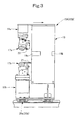
- Fig. 3 is a front view of a joining section.
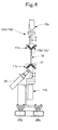
- Fig. 4 is a side view of the joining section.
- Fig. 5 is a detailed side view of aligning sections.
- Fig. 6 is a motion explanation drawing of a cylindrical drum.
- Fig. 7 is another motion explanation drawing of the cylindrical drum.
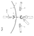
- Fig. 8 is a detail view of Fig. 7 .
- Fig. 9 is a motion explanation drawing of the joining sections.
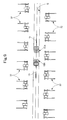
- Fig. 10 is a motion explanation drawing of aligning rollers.
- Fig. 11 is a detail view of Fig. 10 .
- Fig. 12 is a motion explanation drawing of the aligning sections.
- Fig. 13 is a motion explanation drawing of joining rollers and the aligning rollers.
- Fig. 14 is a detail view of Fig. 13 .
- Fig. 15 is a motion explanation drawing of the aligning sections.
- Figs. 16(a) to 16(d) are motion explanation drawings of the joining sections.
- a cylindrical drum 10 wound with a carcass ply W corresponding to one tire is supported on a horizontal rotating shaft 12 of a drum support section 11 so as to be rotatable by a rotational drive section 13 and expansible and contractible by an expansion/contraction mechanism 14.
- a pair of (right and left) joining sections 15A and 15B which run in the axial direction of the drum along an opening portion (gap) G of the cylindrical drum 10 and join ends (a wind start end and a wind finish end) of the carcass ply W facing and entering the opening portion G, and a pair of (front and rear) aligning sections 16A and 16B for approaching and aligning the ends of the carcass ply W during joining by the joining sections 15A and 15B, are arranged below the cylindrical drum 10.
- the opening portion G is designed to be naturally formed when the diameter of the cylindrical drum 10 (respective segments thereof) is increased.
- the joining sections 15A, 15B each include a pair of (upper and lower) cone-shaped joining rollers (toe-in roller devices) 17a and 17b, vertical drive sections 18a and 18b for driving the joining rollers 17a and 17b in a vertical direction by cylinders or the like, and a thin plate-shaped connecting member 19 for connecting the vertical drive sections 18a and 18b.
- the joining sections 15A and 15B can each be allowed to run (slide) by a joining section travel drive motor 24 (see Fig. 2 ) via a pair of (front and rear) linear guides 20a and 20b extending in the axial direction of the drum on a suitable counter.
- the lower vertical drive section 18b has a scooping plate 21 disposed forwardly of the lower joining roller 17b in the advancing direction of the joining roller 17b (see an arrow in Fig. 3 ), the scooping plate 21 being adapted to scoop joint ends of the carcass ply W.
- wedge-shaped slant portions 19a and 19b are formed in their parts which joining or joint end surfaces of the carcass ply W contact, whereby the function of a partition plate for preventing an overlap of the joint end surfaces is imparted.
- an auxiliary roller 22 is adapted to hold the joint ends of the carcass ply W between the auxiliary roller 22 and the scooping plate 21.
- the upper and lower paired cone-shaped joining rollers (toe-in roller devices) 17a and 17b one of the constituent rollers of the lower joining roller 17b is rotationally driven by a cone-shaped roller drive motor 23, whereby the other constituent roller is also rotated in the opposite direction via a bevel gear mechanism.
- the upper joining roller 17a holds the joint ends of the carcass ply W between it and the lower joining roller 17b.
- the joining sections 15A, 15B run, whereby both rollers are rotated in a following manner.
- the function of a so-called shifting roller is achieved.
- the aligning sections 16A and 16B are arranged on both sides of the travel line of the right and left paired joining sections 15A and 15B, and are of the same configuration, except for a part thereof to be described later. That is, the aligning sections 16A and 16B have support stands 28 installed horizontally on a pair of (right and left) counters 25 so as to be ascendable and descendable by the action of a pair of (right and left) parallel links 26 and a pair of (right and left) hoisting cylinders 27.
- the support stand 28 is a long obj ect having a length slightly exceeding the entire length of the cylindrical drum 10 (see Fig. 1 ).
- a slider 30 is placed on the support stand 28 so as to be movable (slidable) in a fore-and-aft direction (a direction orthogonal to the travel line of the joining sections 15A and 15B) via a linear guide 29.
- a two-stage cylinder 31 for slider driving is interposed between the slider 30 and the support stand 28.
- These members (linear guide 29, slider 30, two-stage cylinder 31, etc.) constitute a roller drive section, and a multiplicity of these roller drive sections are installed on each support stand 28 in its right-and-left direction (a direction along the travel line of the joining sections 15A and 15B) (see Fig. 1 ).
- the aligning roller 32 is composed of four rollers, i.e., two rollers arranged forward and rearward, and two rollers arranged on both sides of these rollers overlappingly in the fore-and-aft direction, as shown in Fig. 9 . That is, as many of the aligning rollers 32 as possible are arranged in the fore-and-aft direction (the direction from the central side of the carcass ply toward the joint ends thereof) so that the end side of the carcass ply W located on the respective rollers can be linearly supported and regulated.
- the roller drive sections of the aligning section 16A and the roller drive sections of the aligning section 16B are arranged in a staggered configuration (zigzag arrangement) in the right-and-left direction (the direction along the travel line of the joining sections 15A, 15B).
- the foremost rollers of the aligning rollers 32 of both the aligning section 16A and the aligning section 16B can be located on the line of joining of the carcass ply W (see Fig. 10 ).
- magnets 35a, 35b embedded along the openingportionG of the cylindrical drum 10 can temporarily hold the end sides of the carcass ply W.
- the cylindrical drum 10 having the segments increased in diameter by the expansion/contraction mechanism 14 to form the surface of the cylinder is wound with the carcass ply W cut to a size corresponding to one tire.
- the wind ends of the carcass ply W are positioned at the center of the opening portion G of the cylindrical drum 10. (Winding may start in a lower part of the cylindrical drum 10, but here, starts in an upper part of the cylindrical drum 10.)
- Each end of the carcass ply W sags inwardly of the drum from the opening portion G of the cylindrical drum 10 under its own weight.
- each end of the carcass ply W sags outwardly of the drum from the opening portion G of the cylindrical drum 10 under its own weight, with the result that the joint ends of the carcass ply W become open.
- the amount of the sag is not constant, but varies, depending on the characteristics of the carcass ply W, or the status of handling of the leading end or the rear end of the carcass ply W when wound.
- the right and left paired joining sections 15A and 15B are caused to run (slide) to nearly the center of the joining line of the carcass ply W by the respective joining section travel drive motors 24.
- This position is not necessarily required to be the center, but preferably should not be an end region.
- the carcass ply W wound on the cylindrical drum 10 does not wrinkle or move, because the wedge-shaped slant portions 19a and 19b (see Fig. 3 ) are formed in the portion of the connecting member 19 which the joint end surfaces of the carcass ply W contact.
- the support stands 28 of the front and rear paired aligning sections 16A and 16B are raised by the hoisting cylinders 27 to press the aligning rollers 32 against the cylindrical drum 10 (the lower surface of the carcass ply W) (see the state of the aligning section 16B in Fig. 5 ).
- the aligning rollers 32 are moved from the outside of the opening portion G of the cylindrical drum 10 toward the center of the opening portion G by the two-stage cylinders 31. That is, the two-stage cylinders 31 are moved from the contraction limit position to the extension limit position.
- each aligning roller 32 The constituent rollers of each aligning roller 32 are arranged such that when the foremost roller has moved to the center of the opening portion G of the cylindrical drum 10, the rearmost roller contacts the opening end of the cylindrical drum 10. In this state, the constituent rollers in the rows are nearly horizontal (see Fig. 11 ). At this time, the ends of the carcass ply W (i.e., the wind start end and the wind finish end) are brought close to and aligned with each other, and are nearly in contact. However, gaps along the thickness of the connecting member are formed at the sites of the connecting members 19 of the joining sections 15A and 15B and places ahead of and behind them (see Fig. 12 ).
- the lower joining roller 17b of the left joining section 15B is raised by the vertical drive section 18b to bring the cone part of the joining roller 17b into contact with the lower surface of the ends of the carcass ply W.
- the scooping plate 21 is also raised to make contact with the lower surface of the ends of the carcass ply W, whereby the ends of the carcass ply W (i.e., the wind start end and the wind finish end) separated by the connecting member 19 (the slant portions 19a, 19b) are aligned in a lifted form.
- the upper joining roller 17a of the left joining section 15B is lowered by the vertical drive section 18a to bring the cone part of the joining roller 17a into contact with the upper surface of the ends of the carcass ply W.
- the left joining section 15B is advanced (see the arrow in the drawing) along the linear guides 20a, 20b by the joining section travel drive motor 24.
- the aligning rollers 32 located ahead of the left joining section 15B are sequentially retracted by the two-stage cylinders 31.
- the carcass ply W is sandwiched between the foremost roller and the opening edge portion of the cylindrical drum 10 to hold the carcass ply W (see Figs. 13 and 14 ).
- the right joining section 15A is retracted by the joining section travel drive motor 24 until the joining rollers 17a, 17b of the right joining section 15A are located at the position where joining by the left joining section 15B is started (see Fig. 16(a) ⁇ Fig. 16(b) )). Then, the right joining section 15A is allowed to act in the same manner as is the left joining section 15B, as explained with reference to Figs. 13 to 15 , whereby the axially opposite sides of the ends of the carcass play W (see the arrow in Fig. 15 ) are joined together (see Fig. 16(c) ⁇ Fig. 16(d) ).
- the right and left paired joining sections 15A and 15B are disposed, together with the front and rear paired aligning sections 16A and 16B, below the cylindrical drum 10.
- the property of the ends of the carcass ply W deforming downward (outwardly of the drum) is effectively restrained from below (from outside the cylindrical drum 10), so that accurate joining can be performed without requiring delicate adjustments.
- the cylindrical drum 10 can be simplified, and restrictions on the spaces of the joining sections 15A, 15B and the aligning sections 16A, 16B are relaxed. Also, the rigidity of the joining apparatus is increased to enhance the reliability of the apparatus.
- the installation of the right and left paired joining sections 15A and 15B enables the ends of the wide carcass ply W to be joined smoothly and promptly.
- aligning rollers 32 of the front and rear paired aligning sections 16A and 16B are installed on both sides of the joining line of the carcass ply W and along the joining line.
- the aligning rollers 32 in cooperation with the scoopingplates 21 of the right and left paired joining sections 15A and 15B enable the ends of the carcass ply W to be approached to and aligned with each other with high accuracy.
- Fig. 17 is a front view of the joining section, showing Embodiment 2 of the present invention.
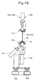
- Fig. 18 is a side view of the joining section.
- the present invention is not limited to the above embodiments, and various changes and modifications may be made without departing from the gist of the present invention.
- the right and left paired joining sections may be limited to one of them, the linear guides of the joining section and the aligning section may be replaced by other moving mechanisms, or the number of the constituent rollers of the aligning roller may be increased or decreased.
- the opening portion in the axial direction of the drum, where the joining section runs may be closed in a continuous cylindrical surface when the carcass ply is wound, but may be provided in an open form only during the joining action.
- the apparatus for joining a carcass ply according to the present invention is preferably used in equipment for producing a large tire in a construction vehicle or the like.
Landscapes
- Engineering & Computer Science (AREA)
- Mechanical Engineering (AREA)
- Textile Engineering (AREA)
- Tyre Moulding (AREA)
Applications Claiming Priority (1)
| Application Number | Priority Date | Filing Date | Title |
|---|---|---|---|
| JP2009038821A JP5221412B2 (ja) | 2009-02-23 | 2009-02-23 | カーカスプライの接合装置 |
Publications (3)
| Publication Number | Publication Date |
|---|---|
| EP2221169A2 true EP2221169A2 (de) | 2010-08-25 |
| EP2221169A3 EP2221169A3 (de) | 2010-12-29 |
| EP2221169B1 EP2221169B1 (de) | 2013-02-27 |
Family
ID=41328878
Family Applications (1)
| Application Number | Title | Priority Date | Filing Date |
|---|---|---|---|
| EP20090167459 Not-in-force EP2221169B1 (de) | 2009-02-23 | 2009-08-07 | Vorrichtung zur Verbindung einer Karkassenlage |
Country Status (5)
| Country | Link |
|---|---|
| US (1) | US8210224B2 (de) |
| EP (1) | EP2221169B1 (de) |
| JP (1) | JP5221412B2 (de) |
| KR (1) | KR101126446B1 (de) |
| CN (1) | CN101811370B (de) |
Cited By (1)
| Publication number | Priority date | Publication date | Assignee | Title |
|---|---|---|---|---|
| EP4017717A4 (de) * | 2019-08-21 | 2023-10-04 | Bridgestone Americas Tire Operations, LLC | Vorrichtung und verfahren zum automatischen nähen von reifenlagen |
Families Citing this family (11)
| Publication number | Priority date | Publication date | Assignee | Title |
|---|---|---|---|---|
| WO2012096275A1 (ja) * | 2011-01-12 | 2012-07-19 | 株式会社ブリヂストン | ゴム部材の接合装置 |
| EP2687355B1 (de) * | 2011-03-15 | 2017-11-15 | Bridgestone Corporation | Automatische reissverschlussvorrichtung für ein folienelement und verfahren zur herstellung des folienelements |
| FR2975039B1 (fr) | 2011-05-10 | 2017-02-10 | Soc De Tech Michelin | Procede de realisation d'une nappe carcasse de pneumatique |
| JP5977494B2 (ja) * | 2011-08-22 | 2016-08-24 | 株式会社ブリヂストン | 空気入りタイヤ用のカーカスプライ素材の端面接合方法及び接合装置 |
| JP5681222B2 (ja) * | 2013-03-01 | 2015-03-04 | 株式会社ブリヂストン | 筒状部材の製造装置及び製造方法 |
| JP6154235B2 (ja) * | 2013-07-29 | 2017-06-28 | 住友ゴム工業株式会社 | ジョイント装置およびジョイント方法 |
| JP5968969B2 (ja) * | 2014-09-24 | 2016-08-10 | 株式会社ブリヂストン | 筒状部材の製造装置及び製造方法 |
| KR101691920B1 (ko) * | 2015-06-01 | 2017-01-03 | 금호타이어 주식회사 | 바디플라이 반제품 접합방법 및 바디플라이 반제품 접합장치 |
| JP7017884B2 (ja) * | 2017-09-04 | 2022-02-09 | Toyo Tire株式会社 | タイヤ部材の製造装置 |
| JP7184602B2 (ja) * | 2018-11-08 | 2022-12-06 | Toyo Tire株式会社 | タイヤ部材の製造装置および製造方法 |
| US11691369B2 (en) | 2019-08-21 | 2023-07-04 | Bridgestone Americas Tire Operations, Llc | Apparatus and method for automatic tire ply sitiching |
Citations (3)
| Publication number | Priority date | Publication date | Assignee | Title |
|---|---|---|---|---|
| JPH0345459B2 (de) | 1982-06-17 | 1991-07-11 | Pioneer Electronic Corp | |
| JP2003019761A (ja) | 2001-07-09 | 2003-01-21 | Yokohama Rubber Co Ltd:The | 帯状ゴム材料の貼合わせ方法及びその貼合わせ方法に使用する成形ドラム |
| JP3420727B2 (ja) | 1999-12-22 | 2003-06-30 | 不二精工株式会社 | カーカスプライの両端部接合装置 |
Family Cites Families (17)
| Publication number | Priority date | Publication date | Assignee | Title |
|---|---|---|---|---|
| IT1158835B (it) * | 1983-03-21 | 1987-02-25 | Firestone Int Dev Spa | Attrezzo motorizzato per la giunzione di tele autoadesive di gomme cruda |
| IT1190035B (it) * | 1986-06-05 | 1988-02-10 | Pirelli | Metodo e apparecchiatura per la giunzione testa a testa di spezzoni di tessuto gommato |
| US4769104A (en) * | 1986-11-11 | 1988-09-06 | Bridgestone Corporation | Apparatus for sticking a tire component member |
| JPS63148417U (de) * | 1987-03-20 | 1988-09-29 | ||
| JP2821773B2 (ja) * | 1989-08-29 | 1998-11-05 | 株式会社ブリヂストン | タイヤ構成部材の圧着装置 |
| IT1241254B (it) * | 1990-06-08 | 1993-12-29 | Firestone International Developments.P.A. | Dispositivo per la giunzione di materiale autoadesivo in foglio di gomma crusa |
| JP3124560B2 (ja) * | 1990-12-28 | 2001-01-15 | 株式会社ブリヂストン | プライ部材の成型方法 |
| JP3192743B2 (ja) * | 1992-03-17 | 2001-07-30 | 株式会社ブリヂストン | 円筒状部材の成型方法および成型装置 |
| JP3442468B2 (ja) | 1994-04-05 | 2003-09-02 | 東洋ゴム工業株式会社 | ラジアルタイヤのスチールプライ接合装置 |
| JP2962647B2 (ja) * | 1994-04-11 | 1999-10-12 | 株式会社ブリヂストン | シート状材料の突合せ接合装置 |
| JP3045459B2 (ja) | 1995-03-07 | 2000-05-29 | 住友ゴム工業株式会社 | カーカスプライの端部接合装置 |
| JP3076509B2 (ja) | 1995-09-04 | 2000-08-14 | 住友ゴム工業株式会社 | カーカスプライの端部接合装置 |
| JP2000167945A (ja) * | 1998-12-08 | 2000-06-20 | Hama Rubber Engineering Kk | タイヤ構成部材の圧着装置 |
| JP4493163B2 (ja) | 1999-06-25 | 2010-06-30 | 株式会社ブリヂストン | シート状未加硫ゴム材料の接合システム |
| JP2001191422A (ja) * | 2000-01-07 | 2001-07-17 | Bridgestone Corp | タイヤ製造工程における円筒状タイヤ構成部材の接合方法 |
| JP2003080611A (ja) * | 2001-09-11 | 2003-03-19 | Yokohama Rubber Co Ltd:The | シート状材料の接合方法及びその接合装置 |
| JP4751243B2 (ja) * | 2006-06-01 | 2011-08-17 | 住友ゴム工業株式会社 | コードプライの側縁部接合装置 |
-
2009
- 2009-02-23 JP JP2009038821A patent/JP5221412B2/ja not_active Expired - Fee Related
- 2009-08-07 EP EP20090167459 patent/EP2221169B1/de not_active Not-in-force
- 2009-08-10 US US12/461,361 patent/US8210224B2/en not_active Expired - Fee Related
- 2009-08-27 CN CN2009101683090A patent/CN101811370B/zh not_active Expired - Fee Related
- 2009-08-28 KR KR20090080138A patent/KR101126446B1/ko not_active Expired - Fee Related
Patent Citations (3)
| Publication number | Priority date | Publication date | Assignee | Title |
|---|---|---|---|---|
| JPH0345459B2 (de) | 1982-06-17 | 1991-07-11 | Pioneer Electronic Corp | |
| JP3420727B2 (ja) | 1999-12-22 | 2003-06-30 | 不二精工株式会社 | カーカスプライの両端部接合装置 |
| JP2003019761A (ja) | 2001-07-09 | 2003-01-21 | Yokohama Rubber Co Ltd:The | 帯状ゴム材料の貼合わせ方法及びその貼合わせ方法に使用する成形ドラム |
Cited By (2)
| Publication number | Priority date | Publication date | Assignee | Title |
|---|---|---|---|---|
| EP4017717A4 (de) * | 2019-08-21 | 2023-10-04 | Bridgestone Americas Tire Operations, LLC | Vorrichtung und verfahren zum automatischen nähen von reifenlagen |
| US12233616B2 (en) | 2019-08-21 | 2025-02-25 | Bridgestone Americas Tire Operations, Llc | Apparatus and method for automatic tire ply stitching |
Also Published As
| Publication number | Publication date |
|---|---|
| US8210224B2 (en) | 2012-07-03 |
| EP2221169A3 (de) | 2010-12-29 |
| JP2010194724A (ja) | 2010-09-09 |
| KR101126446B1 (ko) | 2012-03-29 |
| CN101811370A (zh) | 2010-08-25 |
| CN101811370B (zh) | 2012-12-26 |
| US20100212836A1 (en) | 2010-08-26 |
| JP5221412B2 (ja) | 2013-06-26 |
| KR20100095993A (ko) | 2010-09-01 |
| EP2221169B1 (de) | 2013-02-27 |
Similar Documents
| Publication | Publication Date | Title |
|---|---|---|
| US8210224B2 (en) | Apparatus for joining carcass ply | |
| CN103238247B (zh) | 以电极板组装配机动车的电池壳体的装配站及装配设备 | |
| CN210763429U (zh) | 一种无人化极片上料装置及系统 | |
| CN110114919B (zh) | 卷绕整组设备 | |
| CN204497071U (zh) | 电容器素子卷绕装置 | |
| KR20080105985A (ko) | 스트립 재료, 특히 섬유 또는 강철 로프 스트립을 절단하는절단 장치 및 이를 포함하는 장비 | |
| RU2656044C1 (ru) | Устройство и способ присоединения вместе переднего конца и заднего конца компонента шины | |
| CN104310088B (zh) | 柔性物料加工生产设备 | |
| CN101045504B (zh) | 控制材料条带侧向偏移的装置和方法及使用该装置的系统 | |
| CN105293133B (zh) | 一种卷料的输送跳转装置 | |
| JP6655722B2 (ja) | 連続ストリップの長さを切断してタイヤ構成部材を形成する切断装置および方法 | |
| EP2889511B1 (de) | Drehantriebsmechanismus und vorrichtung zum auftragen von filmetiketten mithilfe dieses mechanismus | |
| EP3067204B1 (de) | Vorrichtung zur herstellung eines elastischen laminats und verfahren zur herstellung elastischen laminats | |
| CN209009802U (zh) | 管状玻纤布堆叠装置 | |
| US9724887B2 (en) | Method for producing a tire carcass ply | |
| CN222180905U (zh) | 去高温布挑引线装置 | |
| CN116460884B (zh) | 穿筋机 | |
| CN213794008U (zh) | 一种标牌穿丝导向装置 | |
| CN207357848U (zh) | 一种弯管机及其顶部模具组件 | |
| CN111689127A (zh) | 纸箱滚筒传输线 | |
| KR20170074306A (ko) | 스트립 권취 장치 | |
| CN104310087A (zh) | 收放料机构 | |
| CN203091981U (zh) | 一种自动打点夹具 | |
| CN109573695A (zh) | 一种用于卷料送卷的驱动机构及其卷料送料机构 | |
| KR102033508B1 (ko) | 코드 강화 플라이의 에지에 검 스트립을 도포하기 위한 장치 및 방법 |
Legal Events
| Date | Code | Title | Description |
|---|---|---|---|
| PUAI | Public reference made under article 153(3) epc to a published international application that has entered the european phase |
Free format text: ORIGINAL CODE: 0009012 |
|
| 17P | Request for examination filed |
Effective date: 20090807 |
|
| AK | Designated contracting states |
Kind code of ref document: A2 Designated state(s): AT BE BG CH CY CZ DE DK EE ES FI FR GB GR HR HU IE IS IT LI LT LU LV MC MK MT NL NO PL PT RO SE SI SK SM TR |
|
| PUAL | Search report despatched |
Free format text: ORIGINAL CODE: 0009013 |
|
| AK | Designated contracting states |
Kind code of ref document: A3 Designated state(s): AT BE BG CH CY CZ DE DK EE ES FI FR GB GR HR HU IE IS IT LI LT LU LV MC MK MT NL NO PL PT RO SE SI SK SM TR |
|
| RIC1 | Information provided on ipc code assigned before grant |
Ipc: B29D 30/24 20060101AFI20100429BHEP Ipc: B29D 30/42 20060101ALI20101124BHEP Ipc: B29D 30/30 20060101ALI20101124BHEP |
|
| GRAP | Despatch of communication of intention to grant a patent |
Free format text: ORIGINAL CODE: EPIDOSNIGR1 |
|
| RIC1 | Information provided on ipc code assigned before grant |
Ipc: B29D 30/30 20060101ALI20120905BHEP Ipc: B29D 30/24 20060101AFI20120905BHEP Ipc: B29D 30/42 20060101ALI20120905BHEP |
|
| GRAS | Grant fee paid |
Free format text: ORIGINAL CODE: EPIDOSNIGR3 |
|
| GRAA | (expected) grant |
Free format text: ORIGINAL CODE: 0009210 |
|
| AK | Designated contracting states |
Kind code of ref document: B1 Designated state(s): AT BE BG CH CY CZ DE DK EE ES FI FR GB GR HR HU IE IS IT LI LT LU LV MC MK MT NL NO PL PT RO SE SI SK SM TR |
|
| REG | Reference to a national code |
Ref country code: GB Ref legal event code: FG4D |
|
| REG | Reference to a national code |
Ref country code: CH Ref legal event code: EP |
|
| REG | Reference to a national code |
Ref country code: AT Ref legal event code: REF Ref document number: 598265 Country of ref document: AT Kind code of ref document: T Effective date: 20130315 |
|
| REG | Reference to a national code |
Ref country code: IE Ref legal event code: FG4D |
|
| REG | Reference to a national code |
Ref country code: DE Ref legal event code: R096 Ref document number: 602009013593 Country of ref document: DE Effective date: 20130425 |
|
| REG | Reference to a national code |
Ref country code: NL Ref legal event code: T3 |
|
| REG | Reference to a national code |
Ref country code: AT Ref legal event code: MK05 Ref document number: 598265 Country of ref document: AT Kind code of ref document: T Effective date: 20130227 |
|
| REG | Reference to a national code |
Ref country code: LT Ref legal event code: MG4D |
|
| PG25 | Lapsed in a contracting state [announced via postgrant information from national office to epo] |
Ref country code: ES Free format text: LAPSE BECAUSE OF FAILURE TO SUBMIT A TRANSLATION OF THE DESCRIPTION OR TO PAY THE FEE WITHIN THE PRESCRIBED TIME-LIMIT Effective date: 20130607 Ref country code: LT Free format text: LAPSE BECAUSE OF FAILURE TO SUBMIT A TRANSLATION OF THE DESCRIPTION OR TO PAY THE FEE WITHIN THE PRESCRIBED TIME-LIMIT Effective date: 20130227 Ref country code: BG Free format text: LAPSE BECAUSE OF FAILURE TO SUBMIT A TRANSLATION OF THE DESCRIPTION OR TO PAY THE FEE WITHIN THE PRESCRIBED TIME-LIMIT Effective date: 20130527 Ref country code: IS Free format text: LAPSE BECAUSE OF FAILURE TO SUBMIT A TRANSLATION OF THE DESCRIPTION OR TO PAY THE FEE WITHIN THE PRESCRIBED TIME-LIMIT Effective date: 20130627 Ref country code: SE Free format text: LAPSE BECAUSE OF FAILURE TO SUBMIT A TRANSLATION OF THE DESCRIPTION OR TO PAY THE FEE WITHIN THE PRESCRIBED TIME-LIMIT Effective date: 20130227 Ref country code: AT Free format text: LAPSE BECAUSE OF FAILURE TO SUBMIT A TRANSLATION OF THE DESCRIPTION OR TO PAY THE FEE WITHIN THE PRESCRIBED TIME-LIMIT Effective date: 20130227 Ref country code: NO Free format text: LAPSE BECAUSE OF FAILURE TO SUBMIT A TRANSLATION OF THE DESCRIPTION OR TO PAY THE FEE WITHIN THE PRESCRIBED TIME-LIMIT Effective date: 20130527 |
|
| PG25 | Lapsed in a contracting state [announced via postgrant information from national office to epo] |
Ref country code: FI Free format text: LAPSE BECAUSE OF FAILURE TO SUBMIT A TRANSLATION OF THE DESCRIPTION OR TO PAY THE FEE WITHIN THE PRESCRIBED TIME-LIMIT Effective date: 20130227 Ref country code: PT Free format text: LAPSE BECAUSE OF FAILURE TO SUBMIT A TRANSLATION OF THE DESCRIPTION OR TO PAY THE FEE WITHIN THE PRESCRIBED TIME-LIMIT Effective date: 20130627 Ref country code: GR Free format text: LAPSE BECAUSE OF FAILURE TO SUBMIT A TRANSLATION OF THE DESCRIPTION OR TO PAY THE FEE WITHIN THE PRESCRIBED TIME-LIMIT Effective date: 20130528 Ref country code: BE Free format text: LAPSE BECAUSE OF FAILURE TO SUBMIT A TRANSLATION OF THE DESCRIPTION OR TO PAY THE FEE WITHIN THE PRESCRIBED TIME-LIMIT Effective date: 20130227 Ref country code: SI Free format text: LAPSE BECAUSE OF FAILURE TO SUBMIT A TRANSLATION OF THE DESCRIPTION OR TO PAY THE FEE WITHIN THE PRESCRIBED TIME-LIMIT Effective date: 20130227 Ref country code: LV Free format text: LAPSE BECAUSE OF FAILURE TO SUBMIT A TRANSLATION OF THE DESCRIPTION OR TO PAY THE FEE WITHIN THE PRESCRIBED TIME-LIMIT Effective date: 20130227 Ref country code: PL Free format text: LAPSE BECAUSE OF FAILURE TO SUBMIT A TRANSLATION OF THE DESCRIPTION OR TO PAY THE FEE WITHIN THE PRESCRIBED TIME-LIMIT Effective date: 20130227 |
|
| PG25 | Lapsed in a contracting state [announced via postgrant information from national office to epo] |
Ref country code: HR Free format text: LAPSE BECAUSE OF FAILURE TO SUBMIT A TRANSLATION OF THE DESCRIPTION OR TO PAY THE FEE WITHIN THE PRESCRIBED TIME-LIMIT Effective date: 20130227 |
|
| PG25 | Lapsed in a contracting state [announced via postgrant information from national office to epo] |
Ref country code: CZ Free format text: LAPSE BECAUSE OF FAILURE TO SUBMIT A TRANSLATION OF THE DESCRIPTION OR TO PAY THE FEE WITHIN THE PRESCRIBED TIME-LIMIT Effective date: 20130227 Ref country code: RO Free format text: LAPSE BECAUSE OF FAILURE TO SUBMIT A TRANSLATION OF THE DESCRIPTION OR TO PAY THE FEE WITHIN THE PRESCRIBED TIME-LIMIT Effective date: 20130227 Ref country code: SK Free format text: LAPSE BECAUSE OF FAILURE TO SUBMIT A TRANSLATION OF THE DESCRIPTION OR TO PAY THE FEE WITHIN THE PRESCRIBED TIME-LIMIT Effective date: 20130227 Ref country code: DK Free format text: LAPSE BECAUSE OF FAILURE TO SUBMIT A TRANSLATION OF THE DESCRIPTION OR TO PAY THE FEE WITHIN THE PRESCRIBED TIME-LIMIT Effective date: 20130227 Ref country code: EE Free format text: LAPSE BECAUSE OF FAILURE TO SUBMIT A TRANSLATION OF THE DESCRIPTION OR TO PAY THE FEE WITHIN THE PRESCRIBED TIME-LIMIT Effective date: 20130227 |
|
| PG25 | Lapsed in a contracting state [announced via postgrant information from national office to epo] |
Ref country code: CY Free format text: LAPSE BECAUSE OF FAILURE TO SUBMIT A TRANSLATION OF THE DESCRIPTION OR TO PAY THE FEE WITHIN THE PRESCRIBED TIME-LIMIT Effective date: 20130227 |
|
| PG25 | Lapsed in a contracting state [announced via postgrant information from national office to epo] |
Ref country code: IT Free format text: LAPSE BECAUSE OF FAILURE TO SUBMIT A TRANSLATION OF THE DESCRIPTION OR TO PAY THE FEE WITHIN THE PRESCRIBED TIME-LIMIT Effective date: 20130227 |
|
| PLBE | No opposition filed within time limit |
Free format text: ORIGINAL CODE: 0009261 |
|
| STAA | Information on the status of an ep patent application or granted ep patent |
Free format text: STATUS: NO OPPOSITION FILED WITHIN TIME LIMIT |
|
| 26N | No opposition filed |
Effective date: 20131128 |
|
| REG | Reference to a national code |
Ref country code: DE Ref legal event code: R097 Ref document number: 602009013593 Country of ref document: DE Effective date: 20131128 |
|
| REG | Reference to a national code |
Ref country code: CH Ref legal event code: PL |
|
| GBPC | Gb: european patent ceased through non-payment of renewal fee |
Effective date: 20130807 |
|
| PG25 | Lapsed in a contracting state [announced via postgrant information from national office to epo] |
Ref country code: MC Free format text: LAPSE BECAUSE OF FAILURE TO SUBMIT A TRANSLATION OF THE DESCRIPTION OR TO PAY THE FEE WITHIN THE PRESCRIBED TIME-LIMIT Effective date: 20130227 Ref country code: LI Free format text: LAPSE BECAUSE OF NON-PAYMENT OF DUE FEES Effective date: 20130831 Ref country code: CH Free format text: LAPSE BECAUSE OF NON-PAYMENT OF DUE FEES Effective date: 20130831 |
|
| REG | Reference to a national code |
Ref country code: IE Ref legal event code: MM4A |
|
| REG | Reference to a national code |
Ref country code: FR Ref legal event code: ST Effective date: 20140430 |
|
| PG25 | Lapsed in a contracting state [announced via postgrant information from national office to epo] |
Ref country code: IE Free format text: LAPSE BECAUSE OF NON-PAYMENT OF DUE FEES Effective date: 20130807 Ref country code: GB Free format text: LAPSE BECAUSE OF NON-PAYMENT OF DUE FEES Effective date: 20130807 |
|
| PG25 | Lapsed in a contracting state [announced via postgrant information from national office to epo] |
Ref country code: FR Free format text: LAPSE BECAUSE OF NON-PAYMENT OF DUE FEES Effective date: 20130902 |
|
| PG25 | Lapsed in a contracting state [announced via postgrant information from national office to epo] |
Ref country code: SM Free format text: LAPSE BECAUSE OF FAILURE TO SUBMIT A TRANSLATION OF THE DESCRIPTION OR TO PAY THE FEE WITHIN THE PRESCRIBED TIME-LIMIT Effective date: 20130227 |
|
| PG25 | Lapsed in a contracting state [announced via postgrant information from national office to epo] |
Ref country code: MT Free format text: LAPSE BECAUSE OF FAILURE TO SUBMIT A TRANSLATION OF THE DESCRIPTION OR TO PAY THE FEE WITHIN THE PRESCRIBED TIME-LIMIT Effective date: 20130227 Ref country code: TR Free format text: LAPSE BECAUSE OF FAILURE TO SUBMIT A TRANSLATION OF THE DESCRIPTION OR TO PAY THE FEE WITHIN THE PRESCRIBED TIME-LIMIT Effective date: 20130227 |
|
| PG25 | Lapsed in a contracting state [announced via postgrant information from national office to epo] |
Ref country code: MK Free format text: LAPSE BECAUSE OF FAILURE TO SUBMIT A TRANSLATION OF THE DESCRIPTION OR TO PAY THE FEE WITHIN THE PRESCRIBED TIME-LIMIT Effective date: 20130227 Ref country code: HU Free format text: LAPSE BECAUSE OF FAILURE TO SUBMIT A TRANSLATION OF THE DESCRIPTION OR TO PAY THE FEE WITHIN THE PRESCRIBED TIME-LIMIT; INVALID AB INITIO Effective date: 20090807 Ref country code: LU Free format text: LAPSE BECAUSE OF NON-PAYMENT OF DUE FEES Effective date: 20130807 |
|
| PGFP | Annual fee paid to national office [announced via postgrant information from national office to epo] |
Ref country code: NL Payment date: 20150709 Year of fee payment: 7 |
|
| PGFP | Annual fee paid to national office [announced via postgrant information from national office to epo] |
Ref country code: DE Payment date: 20150804 Year of fee payment: 7 |
|
| REG | Reference to a national code |
Ref country code: DE Ref legal event code: R119 Ref document number: 602009013593 Country of ref document: DE |
|
| REG | Reference to a national code |
Ref country code: NL Ref legal event code: MM Effective date: 20160901 |
|
| PG25 | Lapsed in a contracting state [announced via postgrant information from national office to epo] |
Ref country code: NL Free format text: LAPSE BECAUSE OF NON-PAYMENT OF DUE FEES Effective date: 20160901 |
|
| PG25 | Lapsed in a contracting state [announced via postgrant information from national office to epo] |
Ref country code: DE Free format text: LAPSE BECAUSE OF NON-PAYMENT OF DUE FEES Effective date: 20170301 |