EP2216632A1 - Débitmètre à pression différentielle et contrôleur de débit - Google Patents
Débitmètre à pression différentielle et contrôleur de débit Download PDFInfo
- Publication number
- EP2216632A1 EP2216632A1 EP20100152417 EP10152417A EP2216632A1 EP 2216632 A1 EP2216632 A1 EP 2216632A1 EP 20100152417 EP20100152417 EP 20100152417 EP 10152417 A EP10152417 A EP 10152417A EP 2216632 A1 EP2216632 A1 EP 2216632A1
- Authority
- EP
- European Patent Office
- Prior art keywords
- flow
- located below
- pressure
- rate
- sensor
- Prior art date
- Legal status (The legal status is an assumption and is not a legal conclusion. Google has not performed a legal analysis and makes no representation as to the accuracy of the status listed.)
- Granted
Links
Images


Classifications
-
- G—PHYSICS
- G01—MEASURING; TESTING
- G01F—MEASURING VOLUME, VOLUME FLOW, MASS FLOW OR LIQUID LEVEL; METERING BY VOLUME
- G01F1/00—Measuring the volume flow or mass flow of fluid or fluent solid material wherein the fluid passes through a meter in a continuous flow
- G01F1/05—Measuring the volume flow or mass flow of fluid or fluent solid material wherein the fluid passes through a meter in a continuous flow by using mechanical effects
- G01F1/34—Measuring the volume flow or mass flow of fluid or fluent solid material wherein the fluid passes through a meter in a continuous flow by using mechanical effects by measuring pressure or differential pressure
- G01F1/36—Measuring the volume flow or mass flow of fluid or fluent solid material wherein the fluid passes through a meter in a continuous flow by using mechanical effects by measuring pressure or differential pressure the pressure or differential pressure being created by the use of flow constriction
- G01F1/40—Details of construction of the flow constriction devices
- G01F1/42—Orifices or nozzles
-
- G—PHYSICS
- G01—MEASURING; TESTING
- G01F—MEASURING VOLUME, VOLUME FLOW, MASS FLOW OR LIQUID LEVEL; METERING BY VOLUME
- G01F1/00—Measuring the volume flow or mass flow of fluid or fluent solid material wherein the fluid passes through a meter in a continuous flow
- G01F1/05—Measuring the volume flow or mass flow of fluid or fluent solid material wherein the fluid passes through a meter in a continuous flow by using mechanical effects
- G01F1/34—Measuring the volume flow or mass flow of fluid or fluent solid material wherein the fluid passes through a meter in a continuous flow by using mechanical effects by measuring pressure or differential pressure
- G01F1/50—Correcting or compensating means
-
- G—PHYSICS
- G01—MEASURING; TESTING
- G01F—MEASURING VOLUME, VOLUME FLOW, MASS FLOW OR LIQUID LEVEL; METERING BY VOLUME
- G01F15/00—Details of, or accessories for, apparatus of groups G01F1/00 - G01F13/00 insofar as such details or appliances are not adapted to particular types of such apparatus
- G01F15/02—Compensating or correcting for variations in pressure, density or temperature
-
- G—PHYSICS
- G05—CONTROLLING; REGULATING
- G05D—SYSTEMS FOR CONTROLLING OR REGULATING NON-ELECTRIC VARIABLES
- G05D7/00—Control of flow
- G05D7/06—Control of flow characterised by the use of electric means
- G05D7/0617—Control of flow characterised by the use of electric means specially adapted for fluid materials
- G05D7/0629—Control of flow characterised by the use of electric means specially adapted for fluid materials characterised by the type of regulator means
- G05D7/0635—Control of flow characterised by the use of electric means specially adapted for fluid materials characterised by the type of regulator means by action on throttling means
-
- Y—GENERAL TAGGING OF NEW TECHNOLOGICAL DEVELOPMENTS; GENERAL TAGGING OF CROSS-SECTIONAL TECHNOLOGIES SPANNING OVER SEVERAL SECTIONS OF THE IPC; TECHNICAL SUBJECTS COVERED BY FORMER USPC CROSS-REFERENCE ART COLLECTIONS [XRACs] AND DIGESTS
- Y10—TECHNICAL SUBJECTS COVERED BY FORMER USPC
- Y10T—TECHNICAL SUBJECTS COVERED BY FORMER US CLASSIFICATION
- Y10T137/00—Fluid handling
- Y10T137/7722—Line condition change responsive valves
- Y10T137/7758—Pilot or servo controlled
- Y10T137/7759—Responsive to change in rate of fluid flow
-
- Y—GENERAL TAGGING OF NEW TECHNOLOGICAL DEVELOPMENTS; GENERAL TAGGING OF CROSS-SECTIONAL TECHNOLOGIES SPANNING OVER SEVERAL SECTIONS OF THE IPC; TECHNICAL SUBJECTS COVERED BY FORMER USPC CROSS-REFERENCE ART COLLECTIONS [XRACs] AND DIGESTS
- Y10—TECHNICAL SUBJECTS COVERED BY FORMER USPC
- Y10T—TECHNICAL SUBJECTS COVERED BY FORMER US CLASSIFICATION
- Y10T137/00—Fluid handling
- Y10T137/7722—Line condition change responsive valves
- Y10T137/7758—Pilot or servo controlled
- Y10T137/7761—Electrically actuated valve
-
- Y—GENERAL TAGGING OF NEW TECHNOLOGICAL DEVELOPMENTS; GENERAL TAGGING OF CROSS-SECTIONAL TECHNOLOGIES SPANNING OVER SEVERAL SECTIONS OF THE IPC; TECHNICAL SUBJECTS COVERED BY FORMER USPC CROSS-REFERENCE ART COLLECTIONS [XRACs] AND DIGESTS
- Y10—TECHNICAL SUBJECTS COVERED BY FORMER USPC
- Y10T—TECHNICAL SUBJECTS COVERED BY FORMER US CLASSIFICATION
- Y10T137/00—Fluid handling
- Y10T137/8593—Systems
- Y10T137/86493—Multi-way valve unit
- Y10T137/86718—Dividing into parallel flow paths with recombining
- Y10T137/86726—Valve with bypass connections
-
- Y—GENERAL TAGGING OF NEW TECHNOLOGICAL DEVELOPMENTS; GENERAL TAGGING OF CROSS-SECTIONAL TECHNOLOGIES SPANNING OVER SEVERAL SECTIONS OF THE IPC; TECHNICAL SUBJECTS COVERED BY FORMER USPC CROSS-REFERENCE ART COLLECTIONS [XRACs] AND DIGESTS
- Y10—TECHNICAL SUBJECTS COVERED BY FORMER USPC
- Y10T—TECHNICAL SUBJECTS COVERED BY FORMER US CLASSIFICATION
- Y10T137/00—Fluid handling
- Y10T137/8593—Systems
- Y10T137/87917—Flow path with serial valves and/or closures
- Y10T137/88046—Biased valve with external operator
Definitions
- the present invention relates to differential-pressure flowmeters and flow-rate controllers used in fluid transport pipes in various industrial fields, such as chemical factories, semiconductor manufacturing, food manufacturing, and biotechnology.
- Japanese Unexamined Patent Application, Publication No. 2009-2901 discloses a known example of a differential-pressure flowmeter and a flow-rate controller used in fluid transport pipes in various industrial fields, such as chemical factories, semiconductor manufacturing, food manufacturing, and biotechnology.
- Two pressure sensors constituting the differential-pressure flowmeter and the flow-rate controller disclosed in Japanese Unexamined Patent Application, Publication No. 2009-2901 each have a characteristic such that an indication value changes as the ambient temperature (surrounding temperature) changes; that is, the indication value increases as the ambient temperature becomes higher.
- the present invention has been made in view of these circumstances, and an object thereof is to provide a differential-pressure flowmeter that can reduce (eliminate) the difference between the ambient temperature of one pressure sensor and the ambient temperature of another pressure sensor so as to allow for accurate and stable pressure measurement, and to provide a flow-rate controller equipped with such a differential-pressure flowmeter.
- the present invention provides the following solutions.
- a differential-pressure flowmeter includes a body having a main fluid channel through which a fluid, whose pressure is to be measured, flows, and two pressure sensors held by the body and arranged in series relative to the main fluid channel, and a temperature balancer composed of a material with high thermal conductivity is accommodated in a recess that is formed in the body located below the two pressure sensors.
- the temperature balancer composed of a material with high thermal conductivity (e.g., aluminum alloy A5052) is embedded (fitted) in the body located below the two pressure sensors, a difference between the ambient temperature of one of the pressure sensors and the ambient temperature of the other pressure sensor can be reduced (eliminated), thereby allowing for accurate and stable pressure measurement.
- a material with high thermal conductivity e.g., aluminum alloy A5052
- a flow-rate controller includes a differential-pressure flowmeter that can reduce (eliminate) a difference between the ambient temperature of one pressure sensor and the ambient temperature of another pressure sensor so as to allow for accurate and stable pressure measurement.
- the accuracy and stability of a measured flow-rate value are enhanced, whereby the accuracy in fluid flow-rate control of the measured flow rate of the fluid flowing through the main fluid channel can be enhanced.
- a body located below a motor that vertically moves a valve plug of a flow-rate control valve and a control board that controls the degree of opening of the flow-rate control valve is connected to a body located below two pressure sensors via a constricted section formed so as to have a width smaller than that of the body located below the two pressure sensors and a height smaller than that of the body located below the two pressure sensors.
- the body located below the two pressure sensors and the body located below the control board and the motor serving as a heat source are connected to each other via the constricted section, heat transmission from the body located below the control board and the motor serving as a heat source to the body located below the two pressure sensors can be minimized, whereby a difference between the ambient temperature of one of the pressure sensors and the ambient temperature of the other pressure sensor can be reduced (eliminated), and the accuracy in fluid flow-rate control of the measured flow rate of the fluid flowing through the main fluid channel can be further enhanced.
- the aforementioned flow-rate controller preferably includes base components disposed between the bodies and an installation surface and fixed to the bodies with fastening members, and a base component positioned between a base component located below the two pressure sensors and a base component located below the motor and the control board is preferably provided with at least one slit that extends therethrough in a thickness direction thereof.
- At least one cooling groove that allows a front surface and a rear surface to communicate with each other be formed in an upper surface of the base component located below the motor and the control board.
- At least one (e.g., two) cooling groove is formed in the upper surface of the base component located below the control board and the motor serving as a heat source and the heat in the body and the base component located below the control board and the motor serving as a heat source is carried away by the air passing through the cooling groove, heat transmission from the body and the base component located below the control board and the motor serving as a heat source to the body and the base component located below the two pressure sensors can be minimized, whereby a difference between the ambient temperature of one of the pressure sensors and the ambient temperature of the other pressure sensor can be reduced (eliminated), and the accuracy in fluid flow-rate control of the measured flow rate of the fluid flowing through the main fluid channel can be further enhanced.
- At least one groove that allows a front surface and a rear surface to communicate with each other be formed in a lower surface of the base component located below the motor and the control board.
- At least one groove that allows a front surface and a rear surface to communicate with each other be formed in a lower surface of the base component located below the two pressure sensors.
- a flow-rate controller since at least one (e.g., one) groove is formed in the lower surface of the base component located below the two pressure sensors, the heat from the installation surface can be prevented from entering the base components, whereby a difference between the ambient temperature of one of the pressure sensors and the ambient temperature of the other pressure sensor can be reduced (eliminated), and the accuracy in fluid flow-rate control of the measured flow rate of the fluid flowing through the main fluid channel can be further enhanced.
- differential-pressure flowmeter With the differential-pressure flowmeter according to the present invention, a difference between the ambient temperature of one of the pressure sensors and the ambient temperature of the other pressure sensor can be reduced (eliminated), thereby advantageously allowing for accurate and stable pressure measurement.
- the flow-rate controller that controls the degree of opening of the flow-rate control valve by using a measured value of the differential-pressure flowmeter according to the present invention, the accuracy and stability of a measured flow-rate value (measured flow rate) are enhanced, whereby the accuracy in fluid flow-rate control of the measured flow rate of the fluid flowing through the main fluid channel can advantageously be enhanced.
- a differential-pressure flowmeter and a flow-rate controller according to an embodiment of the present invention will be described below with reference to Figs. 1 to 5C .
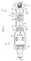
- Fig. 1 is a front view of the flow-rate controller according to this embodiment.
- Fig. 2 is a plan view of Fig. 1 .
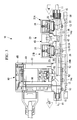
- Fig. 3 is a sectional view taken along line A-A in Fig. 2 .
- Fig. 4 is a sectional view taken along line B-B in Fig. 2 .
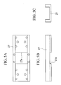
- Fig. 5A is a plan view illustrating a temperature balancer incorporated in the differential-pressure flowmeter according to this embodiment.
- Fig. 5B is a front view of the temperature balancer.
- Fig. 5C is a side view of the temperature balancer.
- a flow-rate controller 10 is a flow-rate controlling device that is incorporated in a pipe 11 communicating with a main fluid channel 12, to be described later, and keeps the fluid flow rate of a liquid (such as a chemical solution) flowing through the main fluid channel 12 constant.
- the flow-rate controller 10 mainly includes a differential-pressure flowmeter 20 for measuring an actual fluid flow rate and a flow-rate control valve 60 capable of controlling the degree of opening of a valve plug.
- the differential-pressure flowmeter 20 is disposed on the upstream side of the flow-rate control valve 60, as viewed in the direction of flow of the fluid flowing through the main fluid channel 12.
- the differential-pressure flowmeter 20 is configured such that a pair of pressure sensors 21A and 21B are arranged in series with an orifice unit 40 therebetween. Specifically, in the differential-pressure flowmeter 20, pressure values of the fluid creating a pressure difference as a result of passing through the orifice unit 40 are individually detected by the two pressure sensors 21A and 21B, and these two pressure values are converted to electrical signals which are then input to a control unit (not shown). The control unit receiving the input signals of the pressure values can measure the flow rate of the fluid flowing through the main fluid channel 12 by converting a differential pressure obtained from the two pressure values to a flow rate.
- first sensor the pressure sensor 21A disposed on the upstream side relative to the orifice unit 40
- second sensor the pressure sensor 21B disposed on the downstream side
- first sensor 21A and the second sensor 21B basically have the same configuration, the following description will be directed to the first sensor 21A disposed on the upstream side.
- the first sensor 21A includes, for example, a sensor body (pressure detecting section) 23 disposed in a pressure introduction channel 22 that branches off upward in a T-shape from the main fluid channel 12 through which the fluid, whose pressure is to be measured, flows.
- the pressure introduction channel 22 that communicates with a sensor accommodation space 25 located thereabove is provided substantially orthogonal to the main fluid channel 12 extending through a body 24.
- the pressure introduction channel 22 has an inclined surface 26 at a wall surface thereof on the downstream side as viewed in the direction of flow of the fluid.
- the inclined surface 26 is inclined in a direction that widens the opening area at the fluid entrance side.
- This inclined surface 26 provides a slope on a sidewall surface of the pressure introduction channel 22 by forming a downstream half thereof in a substantially truncated cone shape, and the pressure introduction channel 22 is configured such that the channel sectional area at the lower side, which is the fluid entrance side communicating with the main fluid channel 12, is larger than that at the fluid exit side communicating with the sensor accommodation space 25.
- the sensor body 23 is not limited in particular so long as it can detect the fluid pressure, but is preferably, for example, a piezoelectric-type pressure sensor, a capacitance-type pressure sensor, or a strain-gauge-type pressure sensor. In this embodiment, a strain-gauge-type pressure sensor is used as the sensor body 23.
- the body 24 is integrally formed by using, for example, polytetrafluoroethylene (PTFE).
- PTFE polytetrafluoroethylene
- a recess 28 that accommodates a temperature balancer 27 shown in Fig. 5 is formed in a lower surface of the body 24 located below the first sensor 21A and the second sensor 21B.
- the temperature balancer 27 is a thin-plate-like component with a rectangular shape in plan view and an angular U-shape in side view, and is integrally formed by using, for example, aluminum alloy A5052.
- a through-hole 27a that is rectangular in plan view is formed in the middle of the temperature balancer 27.
- the body 24 located below the first sensor 21A and the second sensor 21B and a body 24 located below a motor 61 and a control board 66, to be described later, are connected to each other via a connecting section (constricted section) 24A formed so as to have a width (i.e., length in the vertical direction in Fig. 2 ) smaller than that of the body 24 located below the first sensor 21A and the second sensor 21B and a height (i.e., length in the vertical direction in Figs. 1 and 3 ) smaller than that of the body 24 located below the first sensor 21A and the second sensor 21B.
- the main fluid channel 12 is formed within this connecting section 24A.
- a cover 29 is attached to an upper section of the body 24 so as to cover associated components of the sensor body 23.
- the body 24 is firmly supported above a base component 14 with fastening members, such as screws 13, and the body 24 is joined (connected) to the pipe 11, which communicates with the main fluid channel 12, by using cap nuts 15 having a joint structure.
- the base component 14 is integrally formed by using, for example, polypropylene (PP). As shown in Fig. 2 , the base component 14 positioned between the base component 14 located below the first sensor 21A and the second sensor 21B and the base component 14 located below the motor 61 and the control board 66, to be described later, is provided with one or more (seven in this embodiment) slits 14a arrayed in the width direction (i.e., the vertical direction in Fig. 2 ). The slits 14a are through-holes extending through the aforementioned base component 14 in the thickness direction thereof and are formed in the shape of an elongate hole in the longitudinal direction (i.e., the horizontal direction in Fig. 2 ).
- PP polypropylene
- cooling grooves (first grooves) 14b arranged in the longitudinal direction are formed in an upper surface of the base component 14 located below the motor 61 and the control board 66, to be described later.
- the cooling grooves 14b are rectangular in front view and allow the front and rear surfaces to communicate with each other, and are formed along the width direction (i.e., a direction orthogonal to the plane of the drawing in Fig. 1 ).
- At least one (one in this embodiment) groove (second groove) 14c is formed along the width direction (i.e., the direction orthogonal to the plane of the drawing in Figs. 1 and 3 ) in a lower surface of the base component 14 located below the motor 61 and the control board 66, to be described later.
- the groove 14c is rectangular in front view and allows the front and rear surfaces to communicate with each other.
- At least one (one in this embodiment) groove (third groove) 14d is formed along the width direction (i.e., the direction orthogonal to the plane of the drawing in Figs. 1 and 3 ) in a lower surface of the base component 14 located below the first sensor 21A and the second sensor 21B.
- the groove 14d is rectangular in front view and allows the front and rear surfaces to communicate with each other.
- the orifice unit 40 includes an orifice body 41 disposed between the first sensor 21A and the second sensor 21B.
- This orifice body 41 is provided with an orifice channel 42 having a channel sectional area smaller than that of the main fluid channel 12 formed in the body 24 of the first sensor 21A and the second sensor 21B.
- the channel sectional area decreases in a stepwise manner from the main fluid channel 12 to the orifice channel 42 with the minimum diameter.
- One end (i.e., the lower end in Fig. 3 ) of the orifice body 41 that has the orifice channel 42 extends into the body 24.
- the flow-rate control valve 60 is disposed in the body 24 used in common with the first sensor 21A and the second sensor 21B.
- the flow-rate control valve 60 is configured to control the degree of opening so that a difference between a measured flow-rate value of the differential-pressure flowmeter 20 and a preliminarily set flow rate is within a predetermined range.
- the flow-rate control valve 60 has a configuration that opens and closes a needle (valve plug) 62 by vertically moving the needle 62 using a driving mechanism equipped with the motor 61, such as a stepping motor, so as to set the needle 62 in a desired opening position relative to a valve seat 63.
- a driving mechanism equipped with the motor 61 such as a stepping motor
- the driving mechanism and the valve-plug mechanism thereof are not limited in particular so long as the degree of opening of the needle 62 can be adjusted.
- Reference numeral 64 in the drawings denotes a cover that covers the motor 61 and the like
- 65 denotes a lid that covers an opening formed at one end (i.e., the upper end in Fig. 3 ) of the cover 64
- 66 denotes a control board.
- the flow-rate controller 10 Prior to commencing operation, the flow-rate controller 10 having the above configuration inputs and stores, in the control unit, a desired fluid flow rate (referred to as "set flow rate” hereinafter) Qr to be kept constant.
- the control unit operates the needle 62 of the flow-rate control valve 60 so as to set an initial degree of opening thereof to a degree of valve opening corresponding to the input set flow rate Qr.
- the aforementioned flow-rate difference ⁇ Q is compared with a preliminarily set allowable range q.
- the absolute value of the flow-rate difference ⁇ Q is smaller than the allowable range q ( ⁇ Q ⁇ q)
- the needle 62 of the flow-rate control valve 60 is moved in a direction for increasing the degree of opening from the initial degree of opening.
- the flow-rate controller 10 performs feedback control so that the absolute value of the flow-rate difference ⁇ Q obtained by a comparison with the set flow rate Qr on the basis of the measured flow rate Qf input from the differential-pressure flowmeter 20 satisfies the predetermined allowable range, whereby the flow rate of the fluid flowing through the main fluid channel 12 can be kept constant.
- the temperature balancer 27 composed of a material with high thermal conductivity (aluminum alloy A5052 in this embodiment) is embedded (fitted) in the body 24 located below the first sensor 21A and the second sensor 21B, a difference between the ambient temperature of the first sensor 21A and the ambient temperature of the second sensor 21B can be reduced (eliminated), thereby allowing for accurate and stable pressure measurement.
- the flow-rate controller 10 that controls the degree of opening of the flow-rate control valve 60 by using a measured value of the differential-pressure flowmeter 20 according to this embodiment, the accuracy and stability of a measured flow-rate value (measured flow rate Qf) are enhanced, whereby the accuracy in fluid flow-rate control of the measured flow rate Qf of the fluid flowing through the main fluid channel 12 can be enhanced.
- the body 24 located below the first sensor 21A and the second sensor 21B and the body 24 located below the control board 66 and the motor 61 serving as a heat source are connected to each other via the connecting section 24A, heat transmission from the body 24 located below the control board 66 and the motor 61 serving as a heat source to the body 24 located below the first sensor 21A and the second sensor 21B can be minimized, whereby a difference between the ambient temperature of the first sensor 21A and the ambient temperature of the second sensor 21B can be reduced (eliminated), and the accuracy in fluid flow-rate control of the measured flow rate Qf of the fluid flowing through the main fluid channel 12 can be further enhanced.
- the base component 14 positioned between the base component 14 located below the first sensor 21A and the second sensor 21B and the base component 14 located below the control board 66 and the motor 61 serving as a heat source is provided with one or more (seven in this embodiment) slits 14a, heat transmission from the base component 14 located below the control board 66 and the motor 61 serving as a heat source to the base component 14 located below the first sensor 21A and the second sensor 21B can be minimized, whereby a difference between the ambient temperature of the first sensor 21A and the ambient temperature of the second sensor 21B can be reduced (eliminated), and the accuracy in fluid flow-rate control of the measured flow rate Qf of the fluid flowing through the main fluid channel 12 can be further enhanced.
- cooling grooves 14b are formed in the upper surface of the base component 14 located below the control board 66 and the motor 61 serving as a heat source and the heat in the body 24 and the base component 14 located below the control board 66 and the motor 61 serving as a heat source is carried away by the air passing through the cooling grooves 14b, heat transmission from the body 24 and the base component 14 located below the control board 66 and the motor 61 serving as a heat source to the body 24 and the base component 14 located below the first sensor 21A and the second sensor 21B can be minimized, whereby a difference between the ambient temperature of the first sensor 21A and the ambient temperature of the second sensor 21B can be reduced (eliminated), and the accuracy in fluid flow-rate control of the measured flow rate Qf of the fluid flowing through the main fluid channel 12 can be further enhanced.
- the flow-rate controller 10 since at least one (one in this embodiment) groove 14c is formed in the lower surface of the base component 14 located below the control board 66 and the motor 61 serving as a heat source and at least one (one in this embodiment) groove 14d is formed in the lower surface of the base component 14 located below the first sensor 21A and the second sensor 21B, the heat from an installation surface (not shown) can be prevented from entering the base components 14, whereby a difference between the ambient temperature of the first sensor 21A and the ambient temperature of the second sensor 21B can be reduced (eliminated), and the accuracy in fluid flow-rate control of the measured flow rate Qf of the fluid flowing through the main fluid channel 12 can be further enhanced.
Landscapes
- Physics & Mathematics (AREA)
- General Physics & Mathematics (AREA)
- Fluid Mechanics (AREA)
- Engineering & Computer Science (AREA)
- Automation & Control Theory (AREA)
- Measuring Volume Flow (AREA)
- Flow Control (AREA)
Applications Claiming Priority (1)
| Application Number | Priority Date | Filing Date | Title |
|---|---|---|---|
| JP2009024713A JP5209524B2 (ja) | 2009-02-05 | 2009-02-05 | 流量計および流量コントローラ |
Publications (2)
| Publication Number | Publication Date |
|---|---|
| EP2216632A1 true EP2216632A1 (fr) | 2010-08-11 |
| EP2216632B1 EP2216632B1 (fr) | 2014-12-31 |
Family
ID=42199681
Family Applications (2)
| Application Number | Title | Priority Date | Filing Date |
|---|---|---|---|
| EP10151881.9A Active EP2216631B1 (fr) | 2009-02-05 | 2010-01-28 | Débitmètre et contrôle de débit |
| EP20100152417 Active EP2216632B1 (fr) | 2009-02-05 | 2010-02-02 | Débitmètre à pression différentielle et contrôleur de débit |
Family Applications Before (1)
| Application Number | Title | Priority Date | Filing Date |
|---|---|---|---|
| EP10151881.9A Active EP2216631B1 (fr) | 2009-02-05 | 2010-01-28 | Débitmètre et contrôle de débit |
Country Status (4)
| Country | Link |
|---|---|
| US (1) | US8205635B2 (fr) |
| EP (2) | EP2216631B1 (fr) |
| JP (1) | JP5209524B2 (fr) |
| KR (1) | KR101623107B1 (fr) |
Families Citing this family (8)
| Publication number | Priority date | Publication date | Assignee | Title |
|---|---|---|---|---|
| KR101129636B1 (ko) * | 2010-08-20 | 2012-03-28 | 삼성중공업 주식회사 | 유량조절 기능을 가지는 역류방지 댐퍼 |
| US9455398B2 (en) * | 2012-10-30 | 2016-09-27 | Kyocera Corporation | Piezoelectric actuator and mass flow controller provided with same |
| JP2016510925A (ja) * | 2013-03-12 | 2016-04-11 | イリノイ トゥール ワークス インコーポレイティド | ターニングベーン |
| JP6416529B2 (ja) * | 2014-07-23 | 2018-10-31 | 株式会社フジキン | 圧力式流量制御装置 |
| JP6651323B2 (ja) * | 2015-10-02 | 2020-02-19 | サーパス工業株式会社 | 流量調整装置 |
| EP3467389A1 (fr) * | 2017-10-03 | 2019-04-10 | IMI Hydronic Engineering International SA | Soupape de commande d'écoulement de fluide, système de distribution de fluide et procédé de mesure de la pression différentielle |
| CN111853339B (zh) * | 2020-07-27 | 2022-05-20 | 宁波华成阀门有限公司 | 一种流量计型平衡阀及其流量调节方法 |
| US11655912B2 (en) * | 2021-01-14 | 2023-05-23 | Hitachi Metals, Ltd. | Bellows diaphragm assembly |
Citations (6)
| Publication number | Priority date | Publication date | Assignee | Title |
|---|---|---|---|---|
| US4240294A (en) * | 1977-12-16 | 1980-12-23 | Grande Per Olof | Flow meter |
| US5524084A (en) * | 1994-12-30 | 1996-06-04 | Hewlett-Packard Company | Method and apparatus for improved flow and pressure measurement and control |
| US20060008328A1 (en) * | 2004-07-07 | 2006-01-12 | Morgan Daniel P | Flow control apparatus and method with internally isothermal control volume for flow verification |
| EP1944583A1 (fr) * | 2005-09-12 | 2008-07-16 | Surpass Industry Co., Ltd. | Débitmètre à pression différentielle |
| JP2009002901A (ja) | 2007-06-25 | 2009-01-08 | Surpass Kogyo Kk | 圧力センサ、差圧式流量計及び流量コントローラ |
| JP2009024714A (ja) | 2007-07-17 | 2009-02-05 | Ntn Corp | オートテンショナ |
Family Cites Families (10)
| Publication number | Priority date | Publication date | Assignee | Title |
|---|---|---|---|---|
| JPS5782714A (en) * | 1980-11-11 | 1982-05-24 | Toshiba Corp | Measuring device for refrigerating performance |
| US4394816A (en) * | 1981-11-02 | 1983-07-26 | Carrier Corporation | Heat pump system |
| US4461173A (en) * | 1982-05-17 | 1984-07-24 | Sierra Instruments, Inc. | Multirange flowmeter |
| JP3580645B2 (ja) * | 1996-08-12 | 2004-10-27 | 忠弘 大見 | 圧力式流量制御装置 |
| US5944048A (en) * | 1996-10-04 | 1999-08-31 | Emerson Electric Co. | Method and apparatus for detecting and controlling mass flow |
| JP2003316442A (ja) * | 2002-04-26 | 2003-11-07 | Stec Inc | 圧力式流量制御装置 |
| WO2006004674A2 (fr) * | 2004-06-25 | 2006-01-12 | Rivatek Incorporated | Procede et appareil de correction par logiciel d'un debitmetre a ouverture variable |
| JP4856905B2 (ja) * | 2005-06-27 | 2012-01-18 | 国立大学法人東北大学 | 流量レンジ可変型流量制御装置 |
| US7866337B2 (en) * | 2005-07-08 | 2011-01-11 | Entegris, Inc. | Chemically inert flow controller with non-contaminating body |
| JP2007034667A (ja) | 2005-07-27 | 2007-02-08 | Surpass Kogyo Kk | 流量コントローラ、これに用いるレギュレータユニット、バルブユニット |
-
2009
- 2009-02-05 JP JP2009024713A patent/JP5209524B2/ja not_active Expired - Fee Related
-
2010
- 2010-01-19 KR KR1020100004813A patent/KR101623107B1/ko not_active Expired - Fee Related
- 2010-01-28 EP EP10151881.9A patent/EP2216631B1/fr active Active
- 2010-02-02 EP EP20100152417 patent/EP2216632B1/fr active Active
- 2010-02-02 US US12/698,184 patent/US8205635B2/en not_active Expired - Fee Related
Patent Citations (6)
| Publication number | Priority date | Publication date | Assignee | Title |
|---|---|---|---|---|
| US4240294A (en) * | 1977-12-16 | 1980-12-23 | Grande Per Olof | Flow meter |
| US5524084A (en) * | 1994-12-30 | 1996-06-04 | Hewlett-Packard Company | Method and apparatus for improved flow and pressure measurement and control |
| US20060008328A1 (en) * | 2004-07-07 | 2006-01-12 | Morgan Daniel P | Flow control apparatus and method with internally isothermal control volume for flow verification |
| EP1944583A1 (fr) * | 2005-09-12 | 2008-07-16 | Surpass Industry Co., Ltd. | Débitmètre à pression différentielle |
| JP2009002901A (ja) | 2007-06-25 | 2009-01-08 | Surpass Kogyo Kk | 圧力センサ、差圧式流量計及び流量コントローラ |
| JP2009024714A (ja) | 2007-07-17 | 2009-02-05 | Ntn Corp | オートテンショナ |
Also Published As
| Publication number | Publication date |
|---|---|
| KR101623107B1 (ko) | 2016-05-20 |
| US8205635B2 (en) | 2012-06-26 |
| JP2010181263A (ja) | 2010-08-19 |
| US20100193056A1 (en) | 2010-08-05 |
| EP2216631B1 (fr) | 2019-03-13 |
| EP2216631A1 (fr) | 2010-08-11 |
| EP2216632B1 (fr) | 2014-12-31 |
| JP5209524B2 (ja) | 2013-06-12 |
| KR20100090193A (ko) | 2010-08-13 |
Similar Documents
| Publication | Publication Date | Title |
|---|---|---|
| US8225814B2 (en) | Differential-pressure flowmeter and flow-rate controller | |
| EP2216632B1 (fr) | Débitmètre à pression différentielle et contrôleur de débit | |
| KR101424783B1 (ko) | 압력 센서, 차압식 유량계 및 유량 제어기 | |
| US7255012B2 (en) | Process fluid flow device with variable orifice | |
| US7163024B2 (en) | Flow control valve and flow control device | |
| CN205190915U (zh) | 流体调节装置及用于感测其出口压力的传感管 | |
| US20040118200A1 (en) | Device for measuring the flow of a gas or a liquid in a bypass | |
| EP2028456B1 (fr) | Débitmètre multivortex utilisant un débit massique ou volumique comme point de commutation | |
| AU2003299893A1 (en) | Regulator flow measurement apparatus | |
| US9500503B2 (en) | Differential pressure type flowmeter and flow controller provided with the same | |
| KR102771309B1 (ko) | 유량 제어 장치 | |
| JP5135137B2 (ja) | 流量計及び流量制御装置 | |
| US20040244498A1 (en) | Fluid flow meter with fluid flow sensor and oscillation sensor | |
| KR102559872B1 (ko) | 열식 플로센서 | |
| EP3734233A1 (fr) | Appareil de détection de fluide | |
| JP3272797B2 (ja) | 面積流量計 | |
| JP2008002864A (ja) | 熱式流量計および流量制御装置 | |
| JP2006529028A (ja) | 熱線風速計質量流量計測装置及び方法 | |
| SE535494C2 (sv) | Koaxiellt flödesmätarelement och förfarande för att mäta ett flöde | |
| RU2706439C2 (ru) | Устройство измерения расхода жидкости | |
| JP2018066602A (ja) | 流量計 | |
| JP2010078365A (ja) | 差圧式流量測定装置 | |
| KR20160003139U (ko) | 기화기 흐름 측정 시스템 |
Legal Events
| Date | Code | Title | Description |
|---|---|---|---|
| PUAI | Public reference made under article 153(3) epc to a published international application that has entered the european phase |
Free format text: ORIGINAL CODE: 0009012 |
|
| AK | Designated contracting states |
Kind code of ref document: A1 Designated state(s): AT BE BG CH CY CZ DE DK EE ES FI FR GB GR HR HU IE IS IT LI LT LU LV MC MK MT NL NO PL PT RO SE SI SK SM TR |
|
| AX | Request for extension of the european patent |
Extension state: AL BA RS |
|
| 17P | Request for examination filed |
Effective date: 20110124 |
|
| RIC1 | Information provided on ipc code assigned before grant |
Ipc: G05D 7/06 20060101ALI20130319BHEP Ipc: G01F 1/50 20060101AFI20130319BHEP Ipc: G01F 1/42 20060101ALI20130319BHEP Ipc: G01F 15/02 20060101ALI20130319BHEP |
|
| GRAP | Despatch of communication of intention to grant a patent |
Free format text: ORIGINAL CODE: EPIDOSNIGR1 |
|
| INTG | Intention to grant announced |
Effective date: 20140708 |
|
| GRAS | Grant fee paid |
Free format text: ORIGINAL CODE: EPIDOSNIGR3 |
|
| GRAA | (expected) grant |
Free format text: ORIGINAL CODE: 0009210 |
|
| AK | Designated contracting states |
Kind code of ref document: B1 Designated state(s): AT BE BG CH CY CZ DE DK EE ES FI FR GB GR HR HU IE IS IT LI LT LU LV MC MK MT NL NO PL PT RO SE SI SK SM TR |
|
| REG | Reference to a national code |
Ref country code: CH Ref legal event code: EP Ref country code: GB Ref legal event code: FG4D |
|
| REG | Reference to a national code |
Ref country code: IE Ref legal event code: FG4D |
|
| REG | Reference to a national code |
Ref country code: AT Ref legal event code: REF Ref document number: 704678 Country of ref document: AT Kind code of ref document: T Effective date: 20150215 |
|
| REG | Reference to a national code |
Ref country code: DE Ref legal event code: R096 Ref document number: 602010021340 Country of ref document: DE Effective date: 20150219 |
|
| PG25 | Lapsed in a contracting state [announced via postgrant information from national office to epo] |
Ref country code: FI Free format text: LAPSE BECAUSE OF FAILURE TO SUBMIT A TRANSLATION OF THE DESCRIPTION OR TO PAY THE FEE WITHIN THE PRESCRIBED TIME-LIMIT Effective date: 20141231 Ref country code: LT Free format text: LAPSE BECAUSE OF FAILURE TO SUBMIT A TRANSLATION OF THE DESCRIPTION OR TO PAY THE FEE WITHIN THE PRESCRIBED TIME-LIMIT Effective date: 20141231 Ref country code: NO Free format text: LAPSE BECAUSE OF FAILURE TO SUBMIT A TRANSLATION OF THE DESCRIPTION OR TO PAY THE FEE WITHIN THE PRESCRIBED TIME-LIMIT Effective date: 20150331 |
|
| REG | Reference to a national code |
Ref country code: NL Ref legal event code: VDEP Effective date: 20141231 |
|
| REG | Reference to a national code |
Ref country code: LT Ref legal event code: MG4D |
|
| PG25 | Lapsed in a contracting state [announced via postgrant information from national office to epo] |
Ref country code: HR Free format text: LAPSE BECAUSE OF FAILURE TO SUBMIT A TRANSLATION OF THE DESCRIPTION OR TO PAY THE FEE WITHIN THE PRESCRIBED TIME-LIMIT Effective date: 20141231 Ref country code: GR Free format text: LAPSE BECAUSE OF FAILURE TO SUBMIT A TRANSLATION OF THE DESCRIPTION OR TO PAY THE FEE WITHIN THE PRESCRIBED TIME-LIMIT Effective date: 20150401 Ref country code: LV Free format text: LAPSE BECAUSE OF FAILURE TO SUBMIT A TRANSLATION OF THE DESCRIPTION OR TO PAY THE FEE WITHIN THE PRESCRIBED TIME-LIMIT Effective date: 20141231 Ref country code: SE Free format text: LAPSE BECAUSE OF FAILURE TO SUBMIT A TRANSLATION OF THE DESCRIPTION OR TO PAY THE FEE WITHIN THE PRESCRIBED TIME-LIMIT Effective date: 20141231 |
|
| REG | Reference to a national code |
Ref country code: AT Ref legal event code: MK05 Ref document number: 704678 Country of ref document: AT Kind code of ref document: T Effective date: 20141231 |
|
| PG25 | Lapsed in a contracting state [announced via postgrant information from national office to epo] |
Ref country code: NL Free format text: LAPSE BECAUSE OF FAILURE TO SUBMIT A TRANSLATION OF THE DESCRIPTION OR TO PAY THE FEE WITHIN THE PRESCRIBED TIME-LIMIT Effective date: 20141231 |
|
| PG25 | Lapsed in a contracting state [announced via postgrant information from national office to epo] |
Ref country code: SK Free format text: LAPSE BECAUSE OF FAILURE TO SUBMIT A TRANSLATION OF THE DESCRIPTION OR TO PAY THE FEE WITHIN THE PRESCRIBED TIME-LIMIT Effective date: 20141231 Ref country code: ES Free format text: LAPSE BECAUSE OF FAILURE TO SUBMIT A TRANSLATION OF THE DESCRIPTION OR TO PAY THE FEE WITHIN THE PRESCRIBED TIME-LIMIT Effective date: 20141231 Ref country code: RO Free format text: LAPSE BECAUSE OF FAILURE TO SUBMIT A TRANSLATION OF THE DESCRIPTION OR TO PAY THE FEE WITHIN THE PRESCRIBED TIME-LIMIT Effective date: 20141231 Ref country code: CZ Free format text: LAPSE BECAUSE OF FAILURE TO SUBMIT A TRANSLATION OF THE DESCRIPTION OR TO PAY THE FEE WITHIN THE PRESCRIBED TIME-LIMIT Effective date: 20141231 |
|
| PG25 | Lapsed in a contracting state [announced via postgrant information from national office to epo] |
Ref country code: IS Free format text: LAPSE BECAUSE OF FAILURE TO SUBMIT A TRANSLATION OF THE DESCRIPTION OR TO PAY THE FEE WITHIN THE PRESCRIBED TIME-LIMIT Effective date: 20150430 Ref country code: AT Free format text: LAPSE BECAUSE OF FAILURE TO SUBMIT A TRANSLATION OF THE DESCRIPTION OR TO PAY THE FEE WITHIN THE PRESCRIBED TIME-LIMIT Effective date: 20141231 Ref country code: PL Free format text: LAPSE BECAUSE OF FAILURE TO SUBMIT A TRANSLATION OF THE DESCRIPTION OR TO PAY THE FEE WITHIN THE PRESCRIBED TIME-LIMIT Effective date: 20141231 |
|
| PG25 | Lapsed in a contracting state [announced via postgrant information from national office to epo] |
Ref country code: LU Free format text: LAPSE BECAUSE OF FAILURE TO SUBMIT A TRANSLATION OF THE DESCRIPTION OR TO PAY THE FEE WITHIN THE PRESCRIBED TIME-LIMIT Effective date: 20150202 |
|
| REG | Reference to a national code |
Ref country code: CH Ref legal event code: PL |
|
| REG | Reference to a national code |
Ref country code: DE Ref legal event code: R097 Ref document number: 602010021340 Country of ref document: DE |
|
| PG25 | Lapsed in a contracting state [announced via postgrant information from national office to epo] |
Ref country code: EE Free format text: LAPSE BECAUSE OF FAILURE TO SUBMIT A TRANSLATION OF THE DESCRIPTION OR TO PAY THE FEE WITHIN THE PRESCRIBED TIME-LIMIT Effective date: 20141231 Ref country code: DK Free format text: LAPSE BECAUSE OF FAILURE TO SUBMIT A TRANSLATION OF THE DESCRIPTION OR TO PAY THE FEE WITHIN THE PRESCRIBED TIME-LIMIT Effective date: 20141231 Ref country code: CH Free format text: LAPSE BECAUSE OF NON-PAYMENT OF DUE FEES Effective date: 20150228 Ref country code: LI Free format text: LAPSE BECAUSE OF NON-PAYMENT OF DUE FEES Effective date: 20150228 Ref country code: MC Free format text: LAPSE BECAUSE OF FAILURE TO SUBMIT A TRANSLATION OF THE DESCRIPTION OR TO PAY THE FEE WITHIN THE PRESCRIBED TIME-LIMIT Effective date: 20141231 |
|
| PLBE | No opposition filed within time limit |
Free format text: ORIGINAL CODE: 0009261 |
|
| STAA | Information on the status of an ep patent application or granted ep patent |
Free format text: STATUS: NO OPPOSITION FILED WITHIN TIME LIMIT |
|
| REG | Reference to a national code |
Ref country code: IE Ref legal event code: MM4A |
|
| GBPC | Gb: european patent ceased through non-payment of renewal fee |
Effective date: 20150331 |
|
| REG | Reference to a national code |
Ref country code: FR Ref legal event code: ST Effective date: 20151030 |
|
| 26N | No opposition filed |
Effective date: 20151001 |
|
| PG25 | Lapsed in a contracting state [announced via postgrant information from national office to epo] |
Ref country code: IT Free format text: LAPSE BECAUSE OF FAILURE TO SUBMIT A TRANSLATION OF THE DESCRIPTION OR TO PAY THE FEE WITHIN THE PRESCRIBED TIME-LIMIT Effective date: 20141231 |
|
| PG25 | Lapsed in a contracting state [announced via postgrant information from national office to epo] |
Ref country code: GB Free format text: LAPSE BECAUSE OF NON-PAYMENT OF DUE FEES Effective date: 20150331 Ref country code: IE Free format text: LAPSE BECAUSE OF NON-PAYMENT OF DUE FEES Effective date: 20150202 |
|
| PG25 | Lapsed in a contracting state [announced via postgrant information from national office to epo] |
Ref country code: FR Free format text: LAPSE BECAUSE OF NON-PAYMENT OF DUE FEES Effective date: 20150302 Ref country code: SI Free format text: LAPSE BECAUSE OF FAILURE TO SUBMIT A TRANSLATION OF THE DESCRIPTION OR TO PAY THE FEE WITHIN THE PRESCRIBED TIME-LIMIT Effective date: 20141231 |
|
| PG25 | Lapsed in a contracting state [announced via postgrant information from national office to epo] |
Ref country code: BE Free format text: LAPSE BECAUSE OF FAILURE TO SUBMIT A TRANSLATION OF THE DESCRIPTION OR TO PAY THE FEE WITHIN THE PRESCRIBED TIME-LIMIT Effective date: 20141231 |
|
| PG25 | Lapsed in a contracting state [announced via postgrant information from national office to epo] |
Ref country code: MT Free format text: LAPSE BECAUSE OF FAILURE TO SUBMIT A TRANSLATION OF THE DESCRIPTION OR TO PAY THE FEE WITHIN THE PRESCRIBED TIME-LIMIT Effective date: 20141231 |
|
| PG25 | Lapsed in a contracting state [announced via postgrant information from national office to epo] |
Ref country code: BG Free format text: LAPSE BECAUSE OF FAILURE TO SUBMIT A TRANSLATION OF THE DESCRIPTION OR TO PAY THE FEE WITHIN THE PRESCRIBED TIME-LIMIT Effective date: 20141231 Ref country code: HU Free format text: LAPSE BECAUSE OF FAILURE TO SUBMIT A TRANSLATION OF THE DESCRIPTION OR TO PAY THE FEE WITHIN THE PRESCRIBED TIME-LIMIT; INVALID AB INITIO Effective date: 20100202 Ref country code: SM Free format text: LAPSE BECAUSE OF FAILURE TO SUBMIT A TRANSLATION OF THE DESCRIPTION OR TO PAY THE FEE WITHIN THE PRESCRIBED TIME-LIMIT Effective date: 20141231 |
|
| PG25 | Lapsed in a contracting state [announced via postgrant information from national office to epo] |
Ref country code: CY Free format text: LAPSE BECAUSE OF FAILURE TO SUBMIT A TRANSLATION OF THE DESCRIPTION OR TO PAY THE FEE WITHIN THE PRESCRIBED TIME-LIMIT Effective date: 20141231 |
|
| PG25 | Lapsed in a contracting state [announced via postgrant information from national office to epo] |
Ref country code: PT Free format text: LAPSE BECAUSE OF FAILURE TO SUBMIT A TRANSLATION OF THE DESCRIPTION OR TO PAY THE FEE WITHIN THE PRESCRIBED TIME-LIMIT Effective date: 20150501 |
|
| PG25 | Lapsed in a contracting state [announced via postgrant information from national office to epo] |
Ref country code: TR Free format text: LAPSE BECAUSE OF FAILURE TO SUBMIT A TRANSLATION OF THE DESCRIPTION OR TO PAY THE FEE WITHIN THE PRESCRIBED TIME-LIMIT Effective date: 20141231 |
|
| PG25 | Lapsed in a contracting state [announced via postgrant information from national office to epo] |
Ref country code: MK Free format text: LAPSE BECAUSE OF FAILURE TO SUBMIT A TRANSLATION OF THE DESCRIPTION OR TO PAY THE FEE WITHIN THE PRESCRIBED TIME-LIMIT Effective date: 20141231 |
|
| PGFP | Annual fee paid to national office [announced via postgrant information from national office to epo] |
Ref country code: DE Payment date: 20260218 Year of fee payment: 17 |