EP2216618A2 - Pistolet à air pour flêchettes - Google Patents
Pistolet à air pour flêchettes Download PDFInfo
- Publication number
- EP2216618A2 EP2216618A2 EP10450010A EP10450010A EP2216618A2 EP 2216618 A2 EP2216618 A2 EP 2216618A2 EP 10450010 A EP10450010 A EP 10450010A EP 10450010 A EP10450010 A EP 10450010A EP 2216618 A2 EP2216618 A2 EP 2216618A2
- Authority
- EP
- European Patent Office
- Prior art keywords
- gas
- arrow
- barrel
- valve
- sports
- Prior art date
- Legal status (The legal status is an assumption and is not a legal conclusion. Google has not performed a legal analysis and makes no representation as to the accuracy of the status listed.)
- Withdrawn
Links
Images


Classifications
-
- F—MECHANICAL ENGINEERING; LIGHTING; HEATING; WEAPONS; BLASTING
- F41—WEAPONS
- F41B—WEAPONS FOR PROJECTING MISSILES WITHOUT USE OF EXPLOSIVE OR COMBUSTIBLE PROPELLANT CHARGE; WEAPONS NOT OTHERWISE PROVIDED FOR
- F41B11/00—Compressed-gas guns, e.g. air guns; Steam guns
- F41B11/60—Compressed-gas guns, e.g. air guns; Steam guns characterised by the supply of compressed gas
- F41B11/62—Compressed-gas guns, e.g. air guns; Steam guns characterised by the supply of compressed gas with pressure supplied by a gas cartridge
-
- F—MECHANICAL ENGINEERING; LIGHTING; HEATING; WEAPONS; BLASTING
- F41—WEAPONS
- F41B—WEAPONS FOR PROJECTING MISSILES WITHOUT USE OF EXPLOSIVE OR COMBUSTIBLE PROPELLANT CHARGE; WEAPONS NOT OTHERWISE PROVIDED FOR
- F41B11/00—Compressed-gas guns, e.g. air guns; Steam guns
- F41B11/70—Details not provided for in F41B11/50 or F41B11/60
- F41B11/72—Valves; Arrangement of valves
- F41B11/723—Valves; Arrangement of valves for controlling gas pressure for firing the projectile only
-
- F—MECHANICAL ENGINEERING; LIGHTING; HEATING; WEAPONS; BLASTING
- F41—WEAPONS
- F41B—WEAPONS FOR PROJECTING MISSILES WITHOUT USE OF EXPLOSIVE OR COMBUSTIBLE PROPELLANT CHARGE; WEAPONS NOT OTHERWISE PROVIDED FOR
- F41B11/00—Compressed-gas guns, e.g. air guns; Steam guns
- F41B11/80—Compressed-gas guns, e.g. air guns; Steam guns specially adapted for particular purposes
- F41B11/83—Compressed-gas guns, e.g. air guns; Steam guns specially adapted for particular purposes for launching harpoons
Definitions
- the invention relates to a sports device in the form of a pistol, with a barrel and a device for introducing a gaseous medium, in particular CO 2 , in the barrel for expelling a projectile to be arranged in the barrel.
- a gaseous medium in particular CO 2
- the invention has set itself the goal of creating a sports equipment of the type mentioned, which is easy to handle and are easy to detect in the hit from a distance.
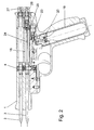
- the sports equipment after Fig. 1 consists of a barrel 1, in which two arrows 2 and 3 are inserted in two superimposed holes with diameters of 5.9 mm.
- the arrows 2 and 3 are fixed by a locking pin 4 in this position.
- an upper locking pin 5 and a lower locking pin 6 are mounted, which are pressed with springs 7 and 8 in recesses 9 and 10 in the arrows 2 and 3.
- the arrows 2 and 3 by spring-mounted in the barrel 1 balls 11 and 12 (ball detents) are held, which engage in corresponding recesses 13 and 14 in the arrows 2,3.
- pressure chambers 15 and 16 which can be set alternately under gas pressure. If the trigger 17 is actuated, the locking pin 4 releases both arrows 2 and 3 from their lock, but only that arrow 2 or 3 is fired, the pressure chamber 15 or 16 is under gas pressure.
- the pressure chambers 15,16 are pressurized in the following manner: In the handle 18, a commercial CO2 gas cartridge 19 is screwed, which is pressed against a piercing pin 20 and a seal 21. If a side mounted on the handle 18 loading lever, which is connected to a rotatable shaft 22, pressed, a gas valve 23 is opened so that CO2 gas flows to the pressure chambers 15,16.
- a switching valve 24 is mounted, which controls the gas flow to either the lower pressure chamber 16 or the upper pressure chamber 15.
- the pressure chambers 15,16 are closed with two fittings 25 and 26, in the leakage gas valves 27 and 28 are installed for safety reasons.
- the leak gas valves 27,28 also serve to relax a pressurized pressure chamber 15,16, if no shot to be delivered.
- Fig. 2 shows the sports device with screwed gas cartridge 19.
- the gas flows through the piercing pin 20 to the closed gas valve 23.
- Both arrows 2,3 are locked in the barrel 1 by the locking pin 4.
- the lower arrow 3 pushes the switching valve 24 in its rearmost position, wherein a bore 29 is released, which allows the inflow of the gas into the lower pressure chamber 16.
- Both gas valves 27, 28 are open.
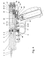
- the gas valve 23 is opened by pressing the loading lever which is connected to the shaft 22.
- the shaft 22 has for this purpose a milled recess 30 which presses on the valve stem 31 of the gas valve 23.
- the gas now flows via an annular channel 32 to a connecting bore 33 and via a longitudinal channel 34 and a bore 29 in the lower pressure chamber 16.
- a transverse bore 35 and a longitudinal bore 36 is arranged, via which the gas passes to a ball check valve 37.
- the ball check valve 37 opens and allows the gas to flow into a space 38 located behind the switching valve 24, the leakage gas valve 28 closes.
- the outflow of the gas in the direction of the bore is prevented by an O-ring seal 39 which is mounted in the barrel 1 and surrounds the arrow 3.
- a recess 40 is milled in the shaft 22, which is so rotated upon actuation of the gas valve 23 that the trigger reset pin 41 blocks, and the trigger 17 can not be operated.
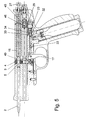
- Fig. 4 was the shaft 22 is rotated back to its original position after the discharge of the loading lever by the closing spring 42 of the gas valve 23 and by acting on the gas valve 23 gas pressure.
- the trigger 17 of the locking pin 4 together with the upper locking pin 5 and the lower locking pin 6 is pulled out of the corresponding recesses 9,10 of the arrows 2,3.
- both arrows 2.3 are released from their lock.
- the lower arrow 3 is fired, since only this is under gas pressure.
- the upper arrow 2 is held for the moment of unlocking by the upper ball catch 11 in the barrel 1.
- the gas pressure in the lower pressure chamber 16 drops to the atmospheric pressure.
- the in the behind the changeover valve 24, located in the space 38 gas is prevented by the ball check valve 37 at a sudden outflow and thus pushes the changeover valve 24 to a stop 44 before.
- the switching valve thus connects the bore 29 via an annular space 45 with the bore 46, so that the gas flows into the upper pressure chamber 15 during the next actuation of the loading lever.
- the gas in the space 38 flows within a few seconds via a small notch 47 which is mounted in the seat of the ball check valve 37, via the pressure chamber 16 and the lower bore of the barrel 1 to the outside. After the gas pressure drops in the space 38, the leakage gas valve 28 opens.
- a flat spring 48 pushes the locking pin 4 back to its original position, the upper arrow 2 is fixed by the locking pin 5 again.
- the trigger 17 is moved back by the return pin 41 and the return spring 43 back to its original position.
- the loading lever can not be actuated for reasons of safety, since the return pin 41 engages in a recess 40 of the shaft 22 and prevents it from rotating.
- the loading lever was actuated again, wherein the shaft 22 has opened the gas valve 23.
- the gas now flows via the annular channel 32 to a bore 33, further via the longitudinal channel 34 to a bore 29 and via the annular space 45 and a further bore 46 in the upper pressure chamber 15.
- the outflow of the gas from the pressure chamber 15 is on the one hand by the Close the leakage gas valve 27, on the other hand by the O-ring seal 49, which encloses the arrow 2, prevented.
- the trigger 17 is actuated, the locking pin 5 is pulled out of the recess 9 of the arrow 2 with the locking pin 4, so that it is shot down. Due to the subsequent pressure drop in the pressure chamber 15, the leakage gas valve 27 opens.
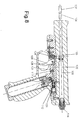
- the sports equipment according to the Fig. 6 to 8 consists of a barrel 101, in which an arrow 102 is inserted in a hole with a diameter of 5.9 mm.
- the arrow 102 is fixed by a locking pin 103 in this position by being pressed into a corresponding recess 104 in the arrow 102.
- a pressure chamber 105 connects, which can be placed under gas pressure.
- the locking pin 103 releases the arrow 102 from its lock, which is fired.
- the pressure chamber 105 is pressurized in the following manner: In the handle 107, a commercially available CO2 gas cartridge 108 is screwed, which is pressed against a piercing pin 109 and a seal 110. When a loading lever attached laterally to the handle 107, which is connected to a rotatable shaft 111, is pressed, a gas valve 112 is opened so that CO 2 gas flows to the pressure chambers 105.
- the pressure chamber 105 is closed with a screw 113, in which a leakage gas valve 114 is installed for safety reasons.
- the leakage gas valve 114 is also used to relax the pressurized pressure chamber 105, if no shot to be delivered.
- Fig. 6 shows the sports device with screwed gas cartridge 108.
- the gas flows through the piercing pin 109 to the closed gas valve 112.
- the arrow 102 is fixed in the barrel 101 by the locking pin 103.
- the leakage gas valve 114 is open.
- the gas valve 112 is opened by pressing the loading lever connected to the shaft 111.
- the shaft 111 has for this purpose a milled recess 115 which presses on the valve stem 116 of the gas valve 112.
- the gas now flows via an annular channel 117 to a connecting bore 118 and via a bore 119 into the pressure chamber 105, the leakage gas valve 114 closes.
- the outflow of the gas in the direction of the bore is prevented by an O-ring seal 120, which is mounted in the barrel 1 and encloses the arrow 102.
- a recess 121 is milled in the shaft 111, which is rotated upon actuation of the loading lever so that the trigger return pin 122 blocks, and the trigger 106 can not be operated.
- the arrow 102 is now ready to fire.
- the loading lever can not be actuated for reasons of safety since the return pin 122 engages in a recess 121 of the shaft 111 and prevents it from rotating.
- a coil spring 124 pushes the locking pin 103 back to its original position.
- the trigger 106 is moved back by the return pin 122 and the return spring 125 back to its original position.
Landscapes
- Engineering & Computer Science (AREA)
- General Engineering & Computer Science (AREA)
- Filling Or Discharging Of Gas Storage Vessels (AREA)
Applications Claiming Priority (1)
| Application Number | Priority Date | Filing Date | Title |
|---|---|---|---|
| AT1942009A AT507796B1 (de) | 2009-02-05 | 2009-02-05 | Sportgerät in form einer pistole |
Publications (1)
| Publication Number | Publication Date |
|---|---|
| EP2216618A2 true EP2216618A2 (fr) | 2010-08-11 |
Family
ID=41803067
Family Applications (1)
| Application Number | Title | Priority Date | Filing Date |
|---|---|---|---|
| EP10450010A Withdrawn EP2216618A2 (fr) | 2009-02-05 | 2010-02-03 | Pistolet à air pour flêchettes |
Country Status (2)
| Country | Link |
|---|---|
| EP (1) | EP2216618A2 (fr) |
| AT (1) | AT507796B1 (fr) |
Cited By (1)
| Publication number | Priority date | Publication date | Assignee | Title |
|---|---|---|---|---|
| ITGE20100099A1 (it) * | 2010-09-10 | 2012-03-11 | Alessandro Sorio | Nuovo fucile subacqueo pneumatico |
-
2009
- 2009-02-05 AT AT1942009A patent/AT507796B1/de not_active IP Right Cessation
-
2010
- 2010-02-03 EP EP10450010A patent/EP2216618A2/fr not_active Withdrawn
Non-Patent Citations (1)
| Title |
|---|
| None |
Cited By (1)
| Publication number | Priority date | Publication date | Assignee | Title |
|---|---|---|---|---|
| ITGE20100099A1 (it) * | 2010-09-10 | 2012-03-11 | Alessandro Sorio | Nuovo fucile subacqueo pneumatico |
Also Published As
| Publication number | Publication date |
|---|---|
| AT507796B1 (de) | 2010-08-15 |
| AT507796A4 (de) | 2010-08-15 |
Similar Documents
| Publication | Publication Date | Title |
|---|---|---|
| DE10127379A1 (de) | Feuereinrichtung für Gasdruckpistole | |
| EP1472501B1 (fr) | Systeme de detente pour armes a feu de poing | |
| DE3235918T1 (de) | Abzug und kombinierte verriegelung und sicherung fuer eine waffe | |
| DE19735737C2 (de) | Repetiergewehr mit einer axial verschiebbar gelagerten Betätigungsvorrichtung | |
| DE2432972C2 (de) | Selbstladepistole | |
| AT507796B1 (de) | Sportgerät in form einer pistole | |
| DE4402951A1 (de) | Auslösemechanismus für ein Gewehr | |
| AT520730B1 (de) | Sportgerät zum Verschiessen von Pfeilen mittels Gasdruck | |
| EP1377787B1 (fr) | Dispositif de tir actionne par du gaz sous pression et dispositif d'alimentation en fluide sous pression pour un tel dispositif de tir | |
| DE2814237A1 (de) | Geschossladeeinrichtung und sicherheitsschloss fuer ein gewehr o.dgl. | |
| DE910625C (de) | Trommelrevolver | |
| EP0081097A2 (fr) | Pistolet à gaz comprimé muni d'une cartouche à gaz carbonique | |
| DE20315550U1 (de) | Abschußvorrichtung zum Abschießen eines durch einen Hund zu apportierenden Dummys | |
| AT526415B1 (de) | Hammerlose Pistole mit Entspannfunktion | |
| DE2237113C3 (de) | Druckluftschußwaffe | |
| DE102022134829B3 (de) | Abzugsystem einer Schusswaffe | |
| AT403523B (de) | Druckgasbetriebene schusswaffe, insbesondere sportwaffe | |
| DE1916617A1 (de) | Jagdgewehr mit uebereinanderliegenden Laeufen | |
| AT56333B (de) | Schloß für mehrläufige Handfeuerwaffen. | |
| DE211259C (fr) | ||
| DE254966C (fr) | ||
| EP1731826B1 (fr) | Déclencheur pour un réservoir sous pression | |
| DE3109515A1 (de) | Co(pfeil abwaerts)2(pfeil abwaerts) - pistole | |
| CH293466A (de) | Geschossbremse an einer Feuerwaffe. | |
| CH341408A (de) | Mit Druckgas betriebene automatische Schiessvorrichtung |
Legal Events
| Date | Code | Title | Description |
|---|---|---|---|
| PUAI | Public reference made under article 153(3) epc to a published international application that has entered the european phase |
Free format text: ORIGINAL CODE: 0009012 |
|
| AK | Designated contracting states |
Kind code of ref document: A2 Designated state(s): AT BE BG CH CY CZ DE DK EE ES FI FR GB GR HR HU IE IS IT LI LT LU LV MC MK MT NL NO PL PT RO SE SI SK SM TR |
|
| AX | Request for extension of the european patent |
Extension state: AL BA RS |
|
| STAA | Information on the status of an ep patent application or granted ep patent |
Free format text: STATUS: THE APPLICATION IS DEEMED TO BE WITHDRAWN |
|
| 18D | Application deemed to be withdrawn |
Effective date: 20120901 |