EP2216618A2 - Airgun for darts - Google Patents
Airgun for darts Download PDFInfo
- Publication number
- EP2216618A2 EP2216618A2 EP10450010A EP10450010A EP2216618A2 EP 2216618 A2 EP2216618 A2 EP 2216618A2 EP 10450010 A EP10450010 A EP 10450010A EP 10450010 A EP10450010 A EP 10450010A EP 2216618 A2 EP2216618 A2 EP 2216618A2
- Authority
- EP
- European Patent Office
- Prior art keywords
- gas
- arrow
- barrel
- valve
- sports
- Prior art date
- Legal status (The legal status is an assumption and is not a legal conclusion. Google has not performed a legal analysis and makes no representation as to the accuracy of the status listed.)
- Withdrawn
Links
Images


Classifications
-
- F—MECHANICAL ENGINEERING; LIGHTING; HEATING; WEAPONS; BLASTING
- F41—WEAPONS
- F41B—WEAPONS FOR PROJECTING MISSILES WITHOUT USE OF EXPLOSIVE OR COMBUSTIBLE PROPELLANT CHARGE; WEAPONS NOT OTHERWISE PROVIDED FOR
- F41B11/00—Compressed-gas guns, e.g. air guns; Steam guns
- F41B11/60—Compressed-gas guns, e.g. air guns; Steam guns characterised by the supply of compressed gas
- F41B11/62—Compressed-gas guns, e.g. air guns; Steam guns characterised by the supply of compressed gas with pressure supplied by a gas cartridge
-
- F—MECHANICAL ENGINEERING; LIGHTING; HEATING; WEAPONS; BLASTING
- F41—WEAPONS
- F41B—WEAPONS FOR PROJECTING MISSILES WITHOUT USE OF EXPLOSIVE OR COMBUSTIBLE PROPELLANT CHARGE; WEAPONS NOT OTHERWISE PROVIDED FOR
- F41B11/00—Compressed-gas guns, e.g. air guns; Steam guns
- F41B11/70—Details not provided for in F41B11/50 or F41B11/60
- F41B11/72—Valves; Arrangement of valves
- F41B11/723—Valves; Arrangement of valves for controlling gas pressure for firing the projectile only
-
- F—MECHANICAL ENGINEERING; LIGHTING; HEATING; WEAPONS; BLASTING
- F41—WEAPONS
- F41B—WEAPONS FOR PROJECTING MISSILES WITHOUT USE OF EXPLOSIVE OR COMBUSTIBLE PROPELLANT CHARGE; WEAPONS NOT OTHERWISE PROVIDED FOR
- F41B11/00—Compressed-gas guns, e.g. air guns; Steam guns
- F41B11/80—Compressed-gas guns, e.g. air guns; Steam guns specially adapted for particular purposes
- F41B11/83—Compressed-gas guns, e.g. air guns; Steam guns specially adapted for particular purposes for launching harpoons
Definitions
- the invention relates to a sports device in the form of a pistol, with a barrel and a device for introducing a gaseous medium, in particular CO 2 , in the barrel for expelling a projectile to be arranged in the barrel.
- a gaseous medium in particular CO 2
- the invention has set itself the goal of creating a sports equipment of the type mentioned, which is easy to handle and are easy to detect in the hit from a distance.
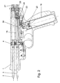
- the sports equipment after Fig. 1 consists of a barrel 1, in which two arrows 2 and 3 are inserted in two superimposed holes with diameters of 5.9 mm.
- the arrows 2 and 3 are fixed by a locking pin 4 in this position.
- an upper locking pin 5 and a lower locking pin 6 are mounted, which are pressed with springs 7 and 8 in recesses 9 and 10 in the arrows 2 and 3.
- the arrows 2 and 3 by spring-mounted in the barrel 1 balls 11 and 12 (ball detents) are held, which engage in corresponding recesses 13 and 14 in the arrows 2,3.
- pressure chambers 15 and 16 which can be set alternately under gas pressure. If the trigger 17 is actuated, the locking pin 4 releases both arrows 2 and 3 from their lock, but only that arrow 2 or 3 is fired, the pressure chamber 15 or 16 is under gas pressure.
- the pressure chambers 15,16 are pressurized in the following manner: In the handle 18, a commercial CO2 gas cartridge 19 is screwed, which is pressed against a piercing pin 20 and a seal 21. If a side mounted on the handle 18 loading lever, which is connected to a rotatable shaft 22, pressed, a gas valve 23 is opened so that CO2 gas flows to the pressure chambers 15,16.
- a switching valve 24 is mounted, which controls the gas flow to either the lower pressure chamber 16 or the upper pressure chamber 15.
- the pressure chambers 15,16 are closed with two fittings 25 and 26, in the leakage gas valves 27 and 28 are installed for safety reasons.
- the leak gas valves 27,28 also serve to relax a pressurized pressure chamber 15,16, if no shot to be delivered.
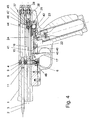
- Fig. 2 shows the sports device with screwed gas cartridge 19.
- the gas flows through the piercing pin 20 to the closed gas valve 23.
- Both arrows 2,3 are locked in the barrel 1 by the locking pin 4.
- the lower arrow 3 pushes the switching valve 24 in its rearmost position, wherein a bore 29 is released, which allows the inflow of the gas into the lower pressure chamber 16.
- Both gas valves 27, 28 are open.
- the gas valve 23 is opened by pressing the loading lever which is connected to the shaft 22.
- the shaft 22 has for this purpose a milled recess 30 which presses on the valve stem 31 of the gas valve 23.
- the gas now flows via an annular channel 32 to a connecting bore 33 and via a longitudinal channel 34 and a bore 29 in the lower pressure chamber 16.
- a transverse bore 35 and a longitudinal bore 36 is arranged, via which the gas passes to a ball check valve 37.
- the ball check valve 37 opens and allows the gas to flow into a space 38 located behind the switching valve 24, the leakage gas valve 28 closes.
- the outflow of the gas in the direction of the bore is prevented by an O-ring seal 39 which is mounted in the barrel 1 and surrounds the arrow 3.
- a recess 40 is milled in the shaft 22, which is so rotated upon actuation of the gas valve 23 that the trigger reset pin 41 blocks, and the trigger 17 can not be operated.
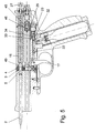
- Fig. 4 was the shaft 22 is rotated back to its original position after the discharge of the loading lever by the closing spring 42 of the gas valve 23 and by acting on the gas valve 23 gas pressure.
- the trigger 17 of the locking pin 4 together with the upper locking pin 5 and the lower locking pin 6 is pulled out of the corresponding recesses 9,10 of the arrows 2,3.
- both arrows 2.3 are released from their lock.
- the lower arrow 3 is fired, since only this is under gas pressure.
- the upper arrow 2 is held for the moment of unlocking by the upper ball catch 11 in the barrel 1.
- the gas pressure in the lower pressure chamber 16 drops to the atmospheric pressure.
- the in the behind the changeover valve 24, located in the space 38 gas is prevented by the ball check valve 37 at a sudden outflow and thus pushes the changeover valve 24 to a stop 44 before.
- the switching valve thus connects the bore 29 via an annular space 45 with the bore 46, so that the gas flows into the upper pressure chamber 15 during the next actuation of the loading lever.
- the gas in the space 38 flows within a few seconds via a small notch 47 which is mounted in the seat of the ball check valve 37, via the pressure chamber 16 and the lower bore of the barrel 1 to the outside. After the gas pressure drops in the space 38, the leakage gas valve 28 opens.
- a flat spring 48 pushes the locking pin 4 back to its original position, the upper arrow 2 is fixed by the locking pin 5 again.
- the trigger 17 is moved back by the return pin 41 and the return spring 43 back to its original position.
- the loading lever can not be actuated for reasons of safety, since the return pin 41 engages in a recess 40 of the shaft 22 and prevents it from rotating.
- the loading lever was actuated again, wherein the shaft 22 has opened the gas valve 23.
- the gas now flows via the annular channel 32 to a bore 33, further via the longitudinal channel 34 to a bore 29 and via the annular space 45 and a further bore 46 in the upper pressure chamber 15.
- the outflow of the gas from the pressure chamber 15 is on the one hand by the Close the leakage gas valve 27, on the other hand by the O-ring seal 49, which encloses the arrow 2, prevented.
- the trigger 17 is actuated, the locking pin 5 is pulled out of the recess 9 of the arrow 2 with the locking pin 4, so that it is shot down. Due to the subsequent pressure drop in the pressure chamber 15, the leakage gas valve 27 opens.
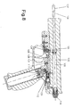
- the sports equipment according to the Fig. 6 to 8 consists of a barrel 101, in which an arrow 102 is inserted in a hole with a diameter of 5.9 mm.
- the arrow 102 is fixed by a locking pin 103 in this position by being pressed into a corresponding recess 104 in the arrow 102.
- a pressure chamber 105 connects, which can be placed under gas pressure.
- the locking pin 103 releases the arrow 102 from its lock, which is fired.
- the pressure chamber 105 is pressurized in the following manner: In the handle 107, a commercially available CO2 gas cartridge 108 is screwed, which is pressed against a piercing pin 109 and a seal 110. When a loading lever attached laterally to the handle 107, which is connected to a rotatable shaft 111, is pressed, a gas valve 112 is opened so that CO 2 gas flows to the pressure chambers 105.
- the pressure chamber 105 is closed with a screw 113, in which a leakage gas valve 114 is installed for safety reasons.
- the leakage gas valve 114 is also used to relax the pressurized pressure chamber 105, if no shot to be delivered.
- Fig. 6 shows the sports device with screwed gas cartridge 108.
- the gas flows through the piercing pin 109 to the closed gas valve 112.
- the arrow 102 is fixed in the barrel 101 by the locking pin 103.
- the leakage gas valve 114 is open.
- the gas valve 112 is opened by pressing the loading lever connected to the shaft 111.
- the shaft 111 has for this purpose a milled recess 115 which presses on the valve stem 116 of the gas valve 112.
- the gas now flows via an annular channel 117 to a connecting bore 118 and via a bore 119 into the pressure chamber 105, the leakage gas valve 114 closes.
- the outflow of the gas in the direction of the bore is prevented by an O-ring seal 120, which is mounted in the barrel 1 and encloses the arrow 102.
- a recess 121 is milled in the shaft 111, which is rotated upon actuation of the loading lever so that the trigger return pin 122 blocks, and the trigger 106 can not be operated.
- the arrow 102 is now ready to fire.
- the loading lever can not be actuated for reasons of safety since the return pin 122 engages in a recess 121 of the shaft 111 and prevents it from rotating.
- a coil spring 124 pushes the locking pin 103 back to its original position.
- the trigger 106 is moved back by the return pin 122 and the return spring 125 back to its original position.
Landscapes
- Engineering & Computer Science (AREA)
- General Engineering & Computer Science (AREA)
- Filling Or Discharging Of Gas Storage Vessels (AREA)
Abstract
Description
Die Erfindung bezieht sich auf ein Sportgerät in Form einer Pistole, mit einem Lauf und einer Vorrichtung zum Einleiten eines gasförmigen Mediums, insbesondere CO2, in den Lauf zum Austreiben eines im Lauf anzuordnenden Geschosses.The invention relates to a sports device in the form of a pistol, with a barrel and a device for introducing a gaseous medium, in particular CO 2 , in the barrel for expelling a projectile to be arranged in the barrel.
Bei bekannten Sportgeräten dieser Art werden sogenannte Diabolokugeln verschossen. Es ist dabei jedoch keine eindeutige Sicherheit bei der Erkennung von Treffern gegeben. Insbesondere kann aus einiger Entfernung nicht erkannt werden, ob der Treffer beim gewünschten Zielpunkt liegt.In known sports equipment of this type so-called diabolo balls are fired. However, there is no clear security in the detection of hits given. In particular, from some distance it can not be recognized whether the hit is at the desired target point.
Die Erfindung hat es sich zum Ziel gesetzt ein Sportgerät der eingangs genannten Art zu schaffen, das einfach zu handhaben ist und bei dem Treffer auch aus größerer Entfernung leicht zu erkennen sind.The invention has set itself the goal of creating a sports equipment of the type mentioned, which is easy to handle and are easy to detect in the hit from a distance.
Erreicht wird dies dadurch, dass das Geschoss ein mit einer Spitze versehener Pfeil ist. Ein solcher Pfeil bleibt bei einem Treffer stecken und kann auch aus größerer Entfernung leicht erkannt werden. Dies ist insbesondere bei einem sportlichen Schießen auf eine Scheibe von Vorteil.This is achieved by the bullet being a pointed arrow. Such an arrow is stuck in a hit and can be easily recognized even from a distance. This is particularly advantageous in a sporting shooting on a disc.
Weitere erfindungsgemäße Merkmale sind in den Unteransprüchen gekennzeichnet.Further features of the invention are characterized in the subclaims.
Nachstehend ist die Erfindung an Hand von in den Zeichnungen dargestellten Ausführungsbeispielen näher beschrieben, ohne auf diese Beispiele beschränkt zu sein. Dabei zeigen jeweils im Schnitt:
-
Fig..1 ein Sportgerät mit zwei Pfeilen; - die
Fig. 2 bis 5 das Sportgerät nachFig. 1 in verschiedenen Phasen; -
Fig. 6 ein Sportgerät mit einem Pfeil; - Die
Fig. 7 und8 das Sportgerät nachFig. 6 in verschiedenen Phasen.
-
Fig..1 a sports equipment with two arrows; - the
Fig. 2 to 5 the sports equipment afterFig. 1 in different phases; -
Fig. 6 a sports equipment with an arrow; - The
Fig. 7 and8th the sports equipment afterFig. 6 in different phases.
Das Sportgerät nach
Die Pfeile 2 und 3 werden durch einen Sperrbolzen 4 in dieser Position fixiert. Im Sperrbolzen 4 sind ein oberer Sperrstift 5 und ein unterer Sperrstift 6 angebracht, die mit Federn 7 und 8 in Ausnehmungen 9 und 10 in den Pfeilen 2 und 3 gedrückt werden. Zusätzlich werden die Pfeile 2 und 3 durch im Lauf 1 gefedert gelagerte Kugeln 11 und 12 (Kugelrasten) gehalten, die in entsprechende Ausnehmungen 13 und 14 in den Pfeilen 2,3 eingreifen.The
Am jeweiligen Pfeilende schließen Druckkammern 15 und 16 an, die abwechselnd unter Gasdruck gesetzt werden können. Wird der Abzug 17 betätigt, löst der Sperrbolzen 4 beide Pfeile 2 und 3 aus ihrer Verriegelung, wobei jedoch nur jener Pfeil 2 oder 3 abgeschossen wird, dessen Druckkammer 15 oder 16 unter Gasdruck steht.At the respective arrow end
Die Druckkammern 15,16 werden auf folgende Weise unter Druck gesetzt: In das Griffstück 18 wird eine handelsübliche CO2-Gaskartusche 19 eingeschraubt, wobei diese gegen einen Durchstoßstift 20 und eine Dichtung 21 gepresst wird. Wird ein seitlich am Griffstück 18 angebrachter Ladehebel, der mit einer drehbaren Welle 22 verbunden ist, gedrückt, wird ein Gasventil 23 geöffnet, sodass CO2-Gas zu den Druckkammern 15,16 strömt.The
In der unteren Druckkammer 16 ist ein Umschaltventil 24 angebracht, welches den Gasfluß entweder zur unteren Druckkammer 16 oder zur oberen Druckkammer 15 steuert.In the
Die Druckkammern 15,16 sind mit zwei Verschraubungen 25 und 26 verschlossen, in die aus Sicherheitsgründen Leckgasventile 27 und 28 eingebaut sind. Die Leckgasventile 27,28 dienen auch zum Entspannen einer unter Druck gesetzten Druckkammer 15,16, falls kein Schuß abgegeben werden soll.The
Gemäß
Das Gas strömt nun über einen Ringkanal 32 zu einer Verbindungsbohrung 33 und über einen Längskanal 34 und eine Bohrung 29 in die untere Druckkammer 16. Im Umschaltventil 24 ist eine Querbohrung 35 und eine Längsbohrung 36 angeordnet, über die das Gas zu einem Kugelrückschlagventil 37 gelangt. Das Kugelrückschlagventil 37 öffnet und läßt das Gas in einen hinter dem Umschaltventil 24 liegenden Raum 38 strömen, wobei das Leckgasventil 28 schließt. Das Abströmen des Gases in Richtung der Laufbohrung wird durch eine O-Ringdichtung 39 verhindert, die im Lauf 1 gelagert ist und den Pfeil 3 umschließt. Aus sicherheitstechnischen Gründen ist in der Welle 22 eine Ausnehmung 40 eingefräst, welche beim Betätigen des Gasventils 23 so verdreht wird, daß der Abzugrückstellstift 41 blockiert, und der Abzug 17 nicht betätigt werden kann.The gas now flows via an
Der untere Pfeil 3 ist nun abschußbereit.The
Gemäß
Nach dem Abschuß des Pfeiles 3 fällt der Gasdruck in der unteren Druckkammer 16 auf den Atmosphärendruck ab. Das in dem hinter dem Umschaltventil 24, im Raum 38 befindliche Gas wird durch das Kugelrückschlagventil 37 an einem plötzlichen Abströmen gehindert und schiebt somit das Umschaltventil 24 bis zu einem Anschlag 44 vor. Das Umschaltventil verbindet damit die Bohrung 29 über einen Ringraum 45 mit der Bohrung 46, sodaß das Gas beim nächsten Betätigen des Ladehebels in die obere Druckkammer 15 strömt.After the firing of the
Das im Raum 38 befindliche Gas strömt innerhalb einiger Sekunden über eine kleine Kerbe 47, die im Sitz des Kugelrückschlagventils 37 angebracht ist, über die Druckkammer 16 und die untere Bohrung des Laufes 1 ins Freie. Nach dem Abfallen des Gasdruckes im Raum 38 öffnet das Leckgasventil 28.The gas in the
Wird nun der Abzug 17 ausgelassen, drückt eine Plattfeder 48 den Sperrbolzen 4 in seine Ausgangsstellung zurück, wobei der obere Pfeil 2 durch den Sperrstift 5 wieder fixiert wird. Der Abzug 17 wird durch den Rückstellstift 41 und die Rückstellfeder 43 wieder in seine ursprüngliche Stellung zurückbewegt.Now, if the
Ist der Abzug 17 gezogen, kann aus Gründen der Sicherheit der Ladehebel nicht betätigt werden, da der Rückstellstift 41 in eine Ausnehmung 40 der Welle 22 eingreift und diese am Verdrehen hindert.If the
Gemäß
Wird nun neuerlich der Abzug 17 betätigt, wird mit dem Sperrbolzen 4 der Sperrstift 5 aus der Ausnehmung 9 des Pfeiles 2 herausgezogen, sodass dieser abgeschossen wird. Durch den anschließenden Druckabfall in der Druckkammer 15 öffnet das Leckgasventil 27.Now again the
Das Sportgerät gemäß den
Am Pfeilende schließt eine Druckkammer 105 an, die unter Gasdruck gesetzt werden kann.At the arrow end, a
Wird der Abzug 106 betätigt, löst der Sperrstift 103 den Pfeil 102 aus seiner Verriegelung, wobei dieser abgeschossen wird.If the
Die Druckkammer 105 wird auf folgende Weise unter Druck gesetzt: In das Griffstück 107 wird eine handelsübliche CO2-Gaskartusche 108 eingeschraubt, wobei diese gegen einen Durchstoßstift 109 und eine Dichtung 110 gepresst wird. Wird ein seitlich am Griffstück 107 angebrachter Ladehebel, der mit einer drehbaren Welle 111 verbunden ist, gedrückt, wird ein Gasventil 112 geöffnet, sodass CO2-Gas zu der Druckkammern 105 strömt.The
Die Druckkammer 105 ist mit einer Verschraubung 113 verschlossen, in die aus Sicherheitsgründen ein Leckgasventil 114 eingebaut ist. Das Leckgasventil 114 dient auch zum Entspannen der unter Druck gesetzten Druckkammer 105, falls kein Schuss abgegeben werden soll.The
In
Das Gas strömt nun über einen Ringkanal 117 zu einer Verbindungsbohrung 118 und über eine Bohrung 119 in die Druckkammer 105, wobei das Leckgasventil 114 schließt. Das Abströmen des Gases in Richtung der Laufbohrung wird durch eine O-Ringdichtung 120 verhindert, die im Lauf 1 gelagert ist und den Pfeil 102 umschließt. Aus sicherheitstechnischen Gründen ist in der Welle 111 eine Ausnehmung 121 eingefräst, welche beim Betätigen des Ladehebels so verdreht wird, dass der Abzugrückstellstift 122 blockiert, und der Abzug 106 nicht betätigt werden kann. Der Pfeil 102 ist nun abschussbereit.The gas now flows via an
In
Ist der Abzug 106 gezogen, kann aus Gründen der Sicherheit der Ladehebel nicht betätigt werden, da der Rückstellstift 122 in eine Ausnehmung 121 der Welle 111 eingreift und diese am Verdrehen hindert.If the
Wird nun der Abzug 106 ausgelassen, drückt eine Schraubenfeder 124 den Sperrstift 103 in seine Ausgangsstellung zurück. Der Abzug 106 wird durch den Rückstellstift 122 und die Rückstellfeder 125 wieder in seine ursprüngliche Stellung zurückbewegt.Now, if the
Claims (8)
Applications Claiming Priority (1)
| Application Number | Priority Date | Filing Date | Title |
|---|---|---|---|
| AT1942009A AT507796B1 (en) | 2009-02-05 | 2009-02-05 | SPORTS DEVICE IN THE FORM OF A PISTOL |
Publications (1)
| Publication Number | Publication Date |
|---|---|
| EP2216618A2 true EP2216618A2 (en) | 2010-08-11 |
Family
ID=41803067
Family Applications (1)
| Application Number | Title | Priority Date | Filing Date |
|---|---|---|---|
| EP10450010A Withdrawn EP2216618A2 (en) | 2009-02-05 | 2010-02-03 | Airgun for darts |
Country Status (2)
| Country | Link |
|---|---|
| EP (1) | EP2216618A2 (en) |
| AT (1) | AT507796B1 (en) |
Cited By (1)
| Publication number | Priority date | Publication date | Assignee | Title |
|---|---|---|---|---|
| ITGE20100099A1 (en) * | 2010-09-10 | 2012-03-11 | Alessandro Sorio | NEW PNEUMATIC DIVE RIFLE |
-
2009
- 2009-02-05 AT AT1942009A patent/AT507796B1/en not_active IP Right Cessation
-
2010
- 2010-02-03 EP EP10450010A patent/EP2216618A2/en not_active Withdrawn
Non-Patent Citations (1)
| Title |
|---|
| None |
Cited By (1)
| Publication number | Priority date | Publication date | Assignee | Title |
|---|---|---|---|---|
| ITGE20100099A1 (en) * | 2010-09-10 | 2012-03-11 | Alessandro Sorio | NEW PNEUMATIC DIVE RIFLE |
Also Published As
| Publication number | Publication date |
|---|---|
| AT507796B1 (en) | 2010-08-15 |
| AT507796A4 (en) | 2010-08-15 |
Similar Documents
| Publication | Publication Date | Title |
|---|---|---|
| DE10127379A1 (en) | Air gun trigger system has holder triggered to release firing system from ready state by either trigger device with driving unit causing continuous movement of other trigger device for fully automatic firing | |
| EP1472501B1 (en) | Trigger mechanism for small arms | |
| DE3235918T1 (en) | DEDUCTION AND COMBINED LOCKING AND SECURING FOR A WEAPON | |
| DE19735737C2 (en) | Repeating rifle with an axially displaceable operating device | |
| DE2432972C2 (en) | Self-loading pistol | |
| AT507796B1 (en) | SPORTS DEVICE IN THE FORM OF A PISTOL | |
| DE4402951A1 (en) | Release mechanism for repeater rifle | |
| AT520730B1 (en) | Sports equipment for shooting arrows by gas pressure | |
| EP1377787B1 (en) | Compressed gas-driven gun device and compressed gas supply device for such a gun device | |
| DE2814237A1 (en) | LOCKING DEVICE AND SECURITY LOCK FOR A RIFLE OR DGL. | |
| DE910625C (en) | Drum revolver | |
| EP0081097A2 (en) | Pneumatic gun with CO2 cartridge | |
| DE20315550U1 (en) | Dummy for training gun dogs comprises tube in which cartridge is mounted which is detonated by spring-loaded bolt when dummy is thrown, bolt being released by lever locked by spring-loaded safety catch | |
| AT526415B1 (en) | Hammerless pistol with decocking function | |
| DE2237113C3 (en) | Compressed air gun | |
| DE102022134829B3 (en) | Trigger system of a firearm | |
| AT403523B (en) | COMPRESSED GAS OPERATED FIREARM, ESPECIALLY SPORTS ARM | |
| DE1916617A1 (en) | Hunting rifle with overlapping barrels | |
| AT56333B (en) | Lock for multi-barreled handguns. | |
| DE211259C (en) | ||
| DE254966C (en) | ||
| EP1731826B1 (en) | Trigger for a pressured container | |
| DE3109515A1 (en) | CO2 pistol | |
| CH293466A (en) | Bullet brake on a firearm. | |
| CH341408A (en) | Automatic shooting device operated with compressed gas |
Legal Events
| Date | Code | Title | Description |
|---|---|---|---|
| PUAI | Public reference made under article 153(3) epc to a published international application that has entered the european phase |
Free format text: ORIGINAL CODE: 0009012 |
|
| AK | Designated contracting states |
Kind code of ref document: A2 Designated state(s): AT BE BG CH CY CZ DE DK EE ES FI FR GB GR HR HU IE IS IT LI LT LU LV MC MK MT NL NO PL PT RO SE SI SK SM TR |
|
| AX | Request for extension of the european patent |
Extension state: AL BA RS |
|
| STAA | Information on the status of an ep patent application or granted ep patent |
Free format text: STATUS: THE APPLICATION IS DEEMED TO BE WITHDRAWN |
|
| 18D | Application deemed to be withdrawn |
Effective date: 20120901 |