EP2211127A1 - Klimaanlage mit wärmepumpe - Google Patents
Klimaanlage mit wärmepumpe Download PDFInfo
- Publication number
- EP2211127A1 EP2211127A1 EP08851740A EP08851740A EP2211127A1 EP 2211127 A1 EP2211127 A1 EP 2211127A1 EP 08851740 A EP08851740 A EP 08851740A EP 08851740 A EP08851740 A EP 08851740A EP 2211127 A1 EP2211127 A1 EP 2211127A1
- Authority
- EP
- European Patent Office
- Prior art keywords
- heat exchanger
- refrigerant
- valve
- outdoor
- compressor
- Prior art date
- Legal status (The legal status is an assumption and is not a legal conclusion. Google has not performed a legal analysis and makes no representation as to the accuracy of the status listed.)
- Withdrawn
Links
Images


Classifications
-
- F—MECHANICAL ENGINEERING; LIGHTING; HEATING; WEAPONS; BLASTING
- F25—REFRIGERATION OR COOLING; COMBINED HEATING AND REFRIGERATION SYSTEMS; HEAT PUMP SYSTEMS; MANUFACTURE OR STORAGE OF ICE; LIQUEFACTION SOLIDIFICATION OF GASES
- F25B—REFRIGERATION MACHINES, PLANTS OR SYSTEMS; COMBINED HEATING AND REFRIGERATION SYSTEMS; HEAT PUMP SYSTEMS
- F25B47/00—Arrangements for preventing or removing deposits or corrosion, not provided for in another subclass
- F25B47/006—Arrangements for preventing or removing deposits or corrosion, not provided for in another subclass for preventing frost
-
- F—MECHANICAL ENGINEERING; LIGHTING; HEATING; WEAPONS; BLASTING
- F25—REFRIGERATION OR COOLING; COMBINED HEATING AND REFRIGERATION SYSTEMS; HEAT PUMP SYSTEMS; MANUFACTURE OR STORAGE OF ICE; LIQUEFACTION SOLIDIFICATION OF GASES
- F25B—REFRIGERATION MACHINES, PLANTS OR SYSTEMS; COMBINED HEATING AND REFRIGERATION SYSTEMS; HEAT PUMP SYSTEMS
- F25B13/00—Compression machines, plants or systems, with reversible cycle
-
- F—MECHANICAL ENGINEERING; LIGHTING; HEATING; WEAPONS; BLASTING
- F25—REFRIGERATION OR COOLING; COMBINED HEATING AND REFRIGERATION SYSTEMS; HEAT PUMP SYSTEMS; MANUFACTURE OR STORAGE OF ICE; LIQUEFACTION SOLIDIFICATION OF GASES
- F25B—REFRIGERATION MACHINES, PLANTS OR SYSTEMS; COMBINED HEATING AND REFRIGERATION SYSTEMS; HEAT PUMP SYSTEMS
- F25B1/00—Compression machines, plants or systems with non-reversible cycle
- F25B1/10—Compression machines, plants or systems with non-reversible cycle with multi-stage compression
-
- F—MECHANICAL ENGINEERING; LIGHTING; HEATING; WEAPONS; BLASTING
- F25—REFRIGERATION OR COOLING; COMBINED HEATING AND REFRIGERATION SYSTEMS; HEAT PUMP SYSTEMS; MANUFACTURE OR STORAGE OF ICE; LIQUEFACTION SOLIDIFICATION OF GASES
- F25B—REFRIGERATION MACHINES, PLANTS OR SYSTEMS; COMBINED HEATING AND REFRIGERATION SYSTEMS; HEAT PUMP SYSTEMS
- F25B2313/00—Compression machines, plants or systems with reversible cycle not otherwise provided for
- F25B2313/027—Compression machines, plants or systems with reversible cycle not otherwise provided for characterised by the reversing means
- F25B2313/0272—Compression machines, plants or systems with reversible cycle not otherwise provided for characterised by the reversing means using bridge circuits of one-way valves
-
- F—MECHANICAL ENGINEERING; LIGHTING; HEATING; WEAPONS; BLASTING
- F25—REFRIGERATION OR COOLING; COMBINED HEATING AND REFRIGERATION SYSTEMS; HEAT PUMP SYSTEMS; MANUFACTURE OR STORAGE OF ICE; LIQUEFACTION SOLIDIFICATION OF GASES
- F25B—REFRIGERATION MACHINES, PLANTS OR SYSTEMS; COMBINED HEATING AND REFRIGERATION SYSTEMS; HEAT PUMP SYSTEMS
- F25B2313/00—Compression machines, plants or systems with reversible cycle not otherwise provided for
- F25B2313/027—Compression machines, plants or systems with reversible cycle not otherwise provided for characterised by the reversing means
- F25B2313/02741—Compression machines, plants or systems with reversible cycle not otherwise provided for characterised by the reversing means using one four-way valve
-
- F—MECHANICAL ENGINEERING; LIGHTING; HEATING; WEAPONS; BLASTING
- F25—REFRIGERATION OR COOLING; COMBINED HEATING AND REFRIGERATION SYSTEMS; HEAT PUMP SYSTEMS; MANUFACTURE OR STORAGE OF ICE; LIQUEFACTION SOLIDIFICATION OF GASES
- F25B—REFRIGERATION MACHINES, PLANTS OR SYSTEMS; COMBINED HEATING AND REFRIGERATION SYSTEMS; HEAT PUMP SYSTEMS
- F25B2400/00—General features or devices for refrigeration machines, plants or systems, combined heating and refrigeration systems or heat-pump systems, i.e. not limited to a particular subgroup of F25B
- F25B2400/13—Economisers
-
- F—MECHANICAL ENGINEERING; LIGHTING; HEATING; WEAPONS; BLASTING
- F25—REFRIGERATION OR COOLING; COMBINED HEATING AND REFRIGERATION SYSTEMS; HEAT PUMP SYSTEMS; MANUFACTURE OR STORAGE OF ICE; LIQUEFACTION SOLIDIFICATION OF GASES
- F25B—REFRIGERATION MACHINES, PLANTS OR SYSTEMS; COMBINED HEATING AND REFRIGERATION SYSTEMS; HEAT PUMP SYSTEMS
- F25B2400/00—General features or devices for refrigeration machines, plants or systems, combined heating and refrigeration systems or heat-pump systems, i.e. not limited to a particular subgroup of F25B
- F25B2400/16—Receivers
Definitions
- the present invention relates to a heat-pump air conditioner in which an auxiliary heat exchanger having an anti-freezing function is provided at a lower part of the outdoor heat exchanger.
- frost In heat-pump air conditioners, during a heating operation, the moisture in the air freezes in the form of frost and deposits on an outdoor heat exchanger serving as an evaporator. Because this inhibits heat exchange, deposition of frost should be detected and a defrosting (frost removing) operation for melting frost should be performed.
- a defrosting (frost removing) operation for melting frost should be performed.
- a phenomenon whereby drain water that has dripped due to defrosting refreezes at a lower part of the outdoor heat exchanger or on a drain pan is observed. In this case, the lower part of the outdoor heat exchanger is clogged by ice, and the ice grows by alternating between melting and freezing. This may result in not only a decrease in capacity, but also, in the worst case, damage to the heat exchanger, deformation of the drain pan, or the like.
- Patent Citation 1 discloses providing an anti-freezing coil at the lower part of the outdoor heat exchanger.
- Patent Citation 2 discloses providing an auxiliary heat exchanger at the lower part of the outdoor heat exchanger. Part of a hot gas refrigerant discharged from a compressor is branched off and is circulated through the auxiliary heat exchanger, and then is merged again at an inlet of a four-way valve, so that the hot gas refrigerant flows constantly.
- Patent Citation 3 discloses providing an auxiliary heat exchanger at the lower part of the outdoor heat exchanger. During heating, a gas-liquid two phase refrigerant having passed through a heating throttle and a hot gas refrigerant discharged from a compressor are introduced into the auxiliary heat exchanger.
- Patent Citation 4 discloses providing a receiver tank at a lower part of the outdoor heat exchanger. A refrigerant is circulated during both cooling and heating.
- Patent Citations 1 to 4 have the effect of preventing the lower part of the outdoor heat exchanger or the drain pan from freezing.
- some of them have demerits in terms of the cooling/heating capacity and performance, and they are not satisfactory as heat-pump air conditioners for cold climate areas, the freezing conditions of which are becoming more and more severe, and as heat-pump air conditioners required to increase the operating range, such as cooling and heating at a low outside-air temperature and cooling and heating under overload conditions.
- Patent Citation 1 relates to an air conditioner specialized for heating, and the structure thereof cannot be applied to a heat-pump air conditioner capable of both cooling and heating operations.
- the disclosures in Patent Citations 2 and 4 have a problem of a decrease in heating capacity, because, during heating, the amount of heat released from the indoor heat exchanger decreases by an amount corresponding to the amount of heat released from the auxiliary heat exchanger and the receiver tank.
- Patent Citation 3 has a problem of causing a decrease in heating capacity, because, during heating, the hot gas refrigerant from the compressor is mixed, through the throttle and the auxiliary heat exchanger, with the low-pressure gas-liquid two phase refrigerant having been reduced in pressure by the heating throttle, decreasing the amount of heat absorbed by the outdoor heat exchanger. Furthermore, although there is a method in which a heater is separately provided, such a method is undesirable since it leads to excessive energy consumption. Accordingly, there is a demand for a heat-pump air conditioner that can reliably prevent the outdoor heat exchanger and the drain pan from freezing without affecting the capacity and performance.
- the present invention has been made in view of the above-described circumstances, and an object thereof is to provide a heat-pump air conditioner that can reliably prevent the outdoor heat exchanger and the drain pan from freezing during heating while maintaining high capacity and high performance, without affecting the capacity and performance.
- a heat-pump air conditioner of the present invention employs the following solutions. That is, a heat-pump air conditioner according to a first aspect of the present invention forms a refrigeration cycle by sequentially connecting, at least, a compressor, a four-way control valve, an outdoor heat exchanger, an outdoor electric expansion valve, an indoor electric expansion valve, and an indoor heat exchanger, and has a gas injection circuit provided in the refrigeration cycle.
- the gas injection circuit vaporizes part of liquid refrigerant in the cycle, cools the liquid refrigerant using latent heat of vaporization, and injects vaporized intermediate-pressure refrigerant into an intermediate intake port of the compressor.
- An auxiliary heat exchanger having an anti-freezing function is provided at a lower part of the outdoor heat exchanger.
- a liquefied injection circuit is connected, which, after the intermediate-pressure refrigerant vaporized in the gas injection circuit is switched by a switching valve to be introduced into the auxiliary heat exchanger, guides the refrigerant to the intermediate intake port of the compressor.
- both the capacity and the performance can be improved.
- the intermediate-pressure refrigerant vaporized in the gas injection circuit and in a saturated gas state can be introduced into the auxiliary heat exchanger through the liquefied injection circuit by the switching valve, and the refrigerant converted into a gas-liquid two phase or a liquid by releasing heat and being cooled can be liquid-injected from the intermediate intake port of the compressor.
- the heating capacity can be further increased when the amounts of circulated refrigerant are the same, and the discharging temperature of the refrigerant can be effectively restricted by increasing the cooling effect.
- the lower part of the outdoor heat exchanger and the drain pan can be heated and prevented from freezing during a heating operation and during defrosting.
- a heat-pump air conditioner forms a refrigeration cycle by sequentially connecting, at least, a compressor, a four-way control valve, an outdoor heat exchanger, an outdoor electric expansion valve, an indoor electric expansion valve, and an indoor heat exchanger, and has a gas injection circuit provided in the refrigeration cycle.
- the gas injection circuit vaporizes part of liquid refrigerant in the cycle, cools the liquid refrigerant using latent heat of vaporization, and injects vaporized intermediate-pressure refrigerant into an intermediate intake port of the compressor.
- An auxiliary heat exchanger having an anti-freezing function is provided at a lower part of the outdoor heat exchanger.
- the auxiliary heat exchanger is connected in parallel to the outdoor electric expansion valve through a check valve that allows a flow of condensed refrigerant from the outdoor heat exchanger, and a bypass circuit having an on-off valve is provided between an intake pipe of the compressor and a point between the check valve and the auxiliary heat exchanger.
- both the capacity and the performance can be improved.
- a high-pressure liquid refrigerant can be constantly supplied to the auxiliary heat exchanger during a heating operation and during defrosting, the lower part of the outdoor heat exchanger and drain pan can be heated by this high-pressure liquid refrigerant.
- the refrigerant supplied to the auxiliary heat exchanger and reduced in temperature by releasing heat can be returned to the intake pipe side of the compressor by the bypass circuit, it does not remain in the auxiliary heat exchanger and freeze by being supercooled or does not lower the amount of heat absorption by being mixed with the refrigerant flowing into the outdoor heat exchanger via the outdoor electric expansion valve.
- the lower part of the outdoor heat exchanger and the drain pan can be prevented from freezing, without lowering the heating capacity.
- the operation may be performed with the on-off valve of the bypass circuit closed.
- the auxiliary heat exchanger can be used as a condenser during a cooling operation, the cooling capacity is not lowered.
- the bypass circuit may be provided with a refrigerant regulating throttle.
- the amount of refrigerant that is returned from the auxiliary heat exchanger to the intake pipe of the compressor through the bypass circuit can be appropriately controlled with the refrigerant regulating throttle provided in the bypass circuit, and the heating effect provided by the high-pressure liquid refrigerant can be ensured.
- the anti-freezing function of the lower part of the outdoor heat exchanger and the drain pan can be reliably maintained.
- a supercooling coil may be provided in parallel with the check valve and the auxiliary heat exchanger, between the outdoor heat exchanger and the outdoor electric expansion valve.
- the cooling capacity can be improved.
- the supercooling coil functioning as a condenser during heating does not lower the vaporizing performance of the outdoor heat exchanger, it does not cause a reduction in the heating capacity.
- a heat-pump air conditioner forms a refrigeration cycle by sequentially connecting, at least, a compressor, a four-way control valve, an outdoor heat exchanger, an outdoor electric expansion valve, an indoor electric expansion valve, and an indoor heat exchanger, and has a gas injection circuit provided in the refrigeration cycle.
- the gas injection circuit vaporizes part of liquid refrigerant in the cycle, cools the liquid refrigerant using latent heat of vaporization, and injects vaporized intermediate-pressure refrigerant into an intermediate intake port of the compressor.
- An auxiliary heat exchanger having an anti-freezing function is provided at a lower part of the outdoor heat exchanger.
- a hot-gas bypass circuit that introduces part of the hot gas discharged from the compressor into the auxiliary heat exchanger through a first on-off valve and guides the refrigerant to a point between the outdoor heat exchanger and the outdoor electric expansion valve through a second on-off valve; a first bypass circuit that guides the refrigerant at the point between the outdoor electric expansion valve and the outdoor heat exchanger to an intake pipe of the compressor via the second on-off valve, the auxiliary heat exchanger, a third on-off valve, and a refrigerant regulating throttle during heating; and a second bypass circuit that condenses, in the auxiliary heat exchanger, the hot gas introduced through the first on-off valve during heating or during defrosting and guides the hot gas to the intake pipe of the compressor via a fourth on-off valve and the refrigerant regulating throttle, are provided.
- both the capacity and the performance can be improved.
- the auxiliary heat exchanger can be made to function as a condenser during a normal cooling operation to increase the condensing performance and to improve the cooling capacity.
- the bypass of the hot gas can be stopped by the first on-off valve so that the condenser is substantially reduced in size to restrict the condensing performance. Therefore, the cooling operation can be continued while maintaining a high pressure.
- the refrigerant adiabatically expanded by the outdoor electric expansion valve can be guided through the first bypass circuit to the auxiliary heat exchanger, which can be made to function as an evaporator, the amount of heat absorption can be increased to improve the heating capacity.
- the hot gas to the auxiliary heat exchanger through the second bypass circuit and making the auxiliary heat exchanger function as a radiator, it can be used to adjust the heating capacity.
- the lower part of the outdoor heat exchanger and the drain pan can be heated and prevented from freezing.
- the first bypass circuit and the second bypass circuit may be provided with a common refrigerant regulating throttle.
- the common refrigerant regulating throttle provided in the first bypass circuit and the second bypass circuit appropriately controls the amount of refrigerant bypassed through the first bypass circuit and the second bypass circuit to the intake pipe of the compressor via the auxiliary heat exchanger.
- the auxiliary heat exchanger can be made to properly function as an evaporator, a radiator, a heater, or the like.
- the auxiliary heat exchanger can be effectively used not only to prevent the lower part of the outdoor heat exchanger and the drain pan from freezing, but also to adjust the heating capacity.
- the operating range can be expanded and the structure can be simplified.
- both the capacity and the performance can be improved.
- the auxiliary heat exchanger provided at the lower part of the outdoor heat exchanger can be made to function as a condenser for the intermediate-pressure refrigerant vaporized in the gas injection circuit, the lower part of the outdoor heat exchanger and the drain pan can be reliably prevented from freezing by means of the released heat.
- the gas-liquid two phase or liquid refrigerant having been condensed in the auxiliary heat exchanger can be liquid-injected from the intermediate intake port of the compressor, the heating capacity can be further improved and the refrigerant discharging temperature can be effectively restricted.
- the operating range can be expanded.
- the heat-pump air conditioner of the present invention improves the capacity and performance due to an economizer effect.
- the high-pressure liquid refrigerant can be constantly supplied to the auxiliary heat exchanger provided at the lower part of the outdoor heat exchanger during heating and during defrosting, the lower part of the outdoor heat exchanger and the drain pan can be reliably prevented from freezing by means of the released heat.
- the high-pressure liquid refrigerant is returned to the intake pipe side of the compressor by the bypass circuit, freezing of the refrigerant remaining in the auxiliary heat exchanger or a decrease in the amount of heat absorption due to the supercooled refrigerant entering the outdoor heat exchanger does not occur.
- high capacity and high performance can be reliably maintained.
- the heat-pump air conditioner of the present invention improvement of the capacity and performance due to an economizer effect can be obtained.
- the auxiliary heat exchanger provided at the lower part of the outdoor heat exchanger can be made to function as a condenser during cooling, the condensing performance can be increased to improve the cooling capacity.
- the function as a condenser can be aborted to restrict the condensing performance, so that the cooling operation can be continued while keeping the high pressure.
- the operating range can be expanded.
- the auxiliary heat exchanger can be made to function as an evaporator during heating, and can be made to function as a radiator under overload heating conditions, it can be used to improve the heating capacity and to adjust the capacity. Furthermore, because it can be made to function as a radiator during defrosting, the lower part of the outdoor heat exchanger and the drain pan can be heated and reliably prevented from freezing.
- FIGS. 1 and 2 show refrigerant circuit diagrams of a heat-pump air conditioner according to the first embodiment of the present invention, in which FIG. 1 shows a cooling cycle, and FIG. 2 shows a heating cycle.
- a multi-type heat-pump air conditioner 1 in which a plurality of indoor units are connected in parallel, is shown.
- the multi-type heat-pump air conditioner 1 is formed of an outdoor unit 2, a refrigerant gas pipe 4 and a refrigerant liquid pipe 5 led out of the outdoor unit 2, and a plurality of indoor units 7A and 7B that are connected in parallel between the refrigerant gas pipe 4 and the refrigerant liquid pipe 5.
- the number of indoor units 7A and 7B is not limited to two, and three or more indoor units can be connected where appropriate.
- the outdoor unit 2 includes an inverter-driven compressor 21 that compresses refrigerant; a four-way control valve 22 that switches the circulation direction of the refrigerant; an outdoor heat exchanger 23 that performs heat exchange between the refrigerant and the outside air; an auxiliary heat exchanger 24 having an anti-freezing function, provided integrally at a lower part of the outdoor heat exchanger 23; an outdoor electric expansion valve (EEVH) 25 for heating; a bridge circuit 27 consisting of a combination of four check valves 26; a receiver 28 that reserves the liquid refrigerant; an intermediate heat exchanger 29 that supercools the liquid refrigerant using latent heat of vaporization of the refrigerant diverted from the liquid pipe; an electric expansion valve (EEVSC) 30 that controls the amount of refrigerant to be diverted to the intermediate heat exchanger 29; and an accumulator 31 that separates liquid from the refrigerant gas to be taken into the compressor 21 and reserves the liquid refrigerant. As it is known, they are connected by refrigerant
- a gas injection circuit 33 which injects the intermediate-pressure refrigerant vaporized by the intermediate heat exchanger 29 into an intermediate intake port 21A provided in the compressor 21, is provided between the intermediate heat exchanger 29 and the compressor 21.
- a liquefied injection circuit 36 that guides the intermediate-pressure refrigerant vaporized by the intermediate heat exchanger 29 to the intermediate intake port 21A of the compressor 21 via the auxiliary heat exchanger 24 having an anti-freezing function, which is provided at the lower part of the outdoor heat exchanger 23, through the solenoid-operated switching valves 34 and 35.
- the solenoid-operated switching valves 34 and 35 may be substituted by a three-way control valve.
- the refrigerant gas pipe 4 and the refrigerant liquid pipe 5 are refrigerant pipes connected to a gas-side service valve and a liquid-side service valve (not shown) provided on the outdoor unit 2 side, and the lengths thereof are determined in accordance with the distances between the outdoor unit 2 and the indoor units 7A and 7B connected thereto, at the time of installation at the site.
- An appropriate number of branching devices are provided at intermediate locations in the refrigerant gas pipe 4 and refrigerant liquid pipe 5, and an appropriate number of indoor units 7A and 7B are connected through these branching devices.
- an enclosed refrigeration cycle 3 is formed.
- Each of the indoor units 7A and 7B includes an indoor heat exchanger 71 that performs heat exchange between the refrigerant and the indoor air to condition the indoor air, an indoor electric expansion valve (EEVC) 72 for cooling, and an indoor fan (not shown) that circulates the indoor air through the indoor heat exchanger 71, and is connected to the branching devices through a branch gas pipe 4A and a branch liquid pipe 5A on the indoor side.
- EEVC indoor electric expansion valve
- a cooling operation is performed as follows. After a high-temperature, high-pressure refrigerant gas compressed by the compressor 21 is discharged into the discharge pipe 32A, as indicated by an arrow in FIG. 1 , the refrigerant gas is circulated toward the gas pipe 32B by the four-way control valve 22 and is then condensed and liquefied by undergoing heat exchange with the outside air, which is blown by an outdoor fan (not shown), in the outdoor heat exchanger 23. After passing through the outdoor electric expansion valve 25 through the liquid pipe 32C, the liquid refrigerant is guided via the bridge circuit 27 to the receiver 28 and is reserved therein, so that the circulated amount is adjusted.
- part of the liquid refrigerant flowing out of the receiver 28 is diverted from the liquid pipe 32C and is cooled by undergoing heat exchange with the intermediate-pressure refrigerant having been adiabatically expanded by the electric expansion valve (EEVSC) 30.
- EEVSC electric expansion valve
- the liquid refrigerant is supercooled to a predetermined degree and is led out of the outdoor unit 2 into the refrigerant liquid pipe 5, through the bridge circuit 27 and liquid pipe 32C.
- the liquid refrigerant led out into the refrigerant liquid pipe 5 is diverted into the branch liquid pipe 5A of the indoor units 7A and 7B by a branching device (not shown).
- the liquid refrigerant diverted into the branch liquid pipe 5A flows into each of the indoor units 7A and 7B and is adiabatically expanded by the indoor electric expansion valve (EEVC) 72.
- the liquid refrigerant converted into a gas-liquid two phase flow flows in the indoor heat exchanger 71.
- the indoor heat exchanger 71 performs heat exchange with the refrigerant and the indoor air circulated by the indoor fan (not shown), and the indoor air is cooled and used to cool the room.
- the refrigerant converted into gas reaches the branching device through the branch gas pipe 4A and is merged with the refrigerant gas from the other one of the indoor units 7A and 7B at the refrigerant gas pipe 4.
- the refrigerant gas merged at the refrigerant gas pipe 4 returns again to the outdoor unit 2, passes through the gas pipe 32D and the four-way control valve 22, reaches the intake pipe 32E, and is introduced into the accumulator 31. Liquid contained in the refrigerant gas is separated by the accumulator 31, and only gas is taken into the compressor 21. This refrigerant is compressed again in the compressor 21.
- the cooling operation is performed by repeating the above-described cycle.
- a heating operation is performed as follows. After a high-temperature, high-pressure refrigerant gas compressed by the compressor 21 is discharged into the discharge pipe 32A, as indicated by an arrow in FIG. 2 , the refrigerant gas is circulated toward the gas pipe 32D by the four-way control valve 22. This refrigerant is led out of the outdoor unit 2 through the refrigerant gas pipe 4 and is introduced into the indoor units 7A and 7B through the branch gas pipe 4A connected to the refrigerant gas pipe 4 via the branching device.
- the high-temperature, high-pressure refrigerant gas introduced into each of the indoor units 7A and 7B is subjected to heat exchange with the indoor air circulated by the indoor fan (not shown) in the indoor heat exchanger 71, and the indoor air is heated and used to heat the room.
- the liquid refrigerant condensed and liquefied by undergoing heat exchange with the indoor air passes through the indoor electric expansion valve (EEVC) 72 and the branch liquid pipe 5A, is merged with the refrigerant from the other one of the indoor units 7A and 7B, and returns to the outdoor unit 2 through the refrigerant liquid pipe 5.
- EEVC indoor electric expansion valve
- the degree of opening of the indoor electric expansion valve (EEVC) 72 is controlled so that the degree of supercooling of the refrigerant is a constant value at the outlet of the indoor heat exchanger 71, serving as a condenser.
- the refrigerant returned to the outdoor unit 2 passes through the liquid pipe 32C and the bridge circuit 27, flows into the receiver 28, and is reserved therein so that the circulated amount is adjusted.
- the liquid refrigerant flowing out of the receiver 28 is supercooled similarly to the case of the cooling in the intermediate heat exchanger 29, passes through the liquid pipe 32C and the bridge circuit 27, and reaches the outdoor electric expansion valve (EEVH) 25, where it is adiabatically expanded.
- EEVH outdoor electric expansion valve
- the liquid refrigerant passes through the liquid pipe 32C and flows into the outdoor heat exchanger 23.
- the outdoor heat exchanger 23 performs heat exchange with the refrigerant and the outside air blown by the outdoor fan (not shown), and the refrigerant is vaporized by absorbing heat from the outside air.
- This refrigerant is introduced from the outdoor heat exchanger 23 into the accumulator 31 through the gas pipe 32B, the four-way control valve 22, and the intake pipe 32E. Liquid contained in the refrigerant gas is separated by the accumulator 31, and only gas is taken into the compressor 21. This refrigerant is compressed again in the compressor 21. The heating operation is performed by repeating the above-described cycle.
- the moisture in the outside air may freeze in the form of frost and deposit on the surface of the outdoor heat exchanger 23. Because this frost inhibits heat exchange in the outdoor heat exchanger 23, when deposition of frost is detected, a defrosting (frost removing) operation for melting frost is performed.
- the defrosting operation is performed by switching the refrigeration cycle 3 to the cooling cycle by the four-way control valve 22. This causes the high-temperature, high-pressure refrigerant gas (hot gas) discharged from the compressor 21 to be introduced into the outdoor heat exchanger 23, and the heat thereof heats and melts the frost on the surface of the heat exchanger from the inside.
- the melted frost falls, as drain water, onto the drain pan (the bottom plate of the indoor unit 2) on which the outdoor heat exchanger 23 is installed, and is discharged outside from a drain port.
- the intermediate-pressure refrigerant vaporized by cooling the liquid refrigerant in the intermediate heat exchanger 29 passes through the gas injection circuit 33 and is guided to the intermediate intake port 21A of the compressor 21.
- the solenoid-operated switching valve 34 is switched to "close” and the solenoid-operated switching valve 35 is switched to "open"
- the saturated intermediate-pressure refrigerant gas having left the intermediate heat exchanger 29 is guided from the gas injection circuit 33 to the liquefied injection circuit 36 and is introduced into the auxiliary heat exchanger 24 provided at the lower part of the outdoor heat exchanger 23.
- the intermediate-pressure refrigerant gas is subjected to heat exchange with the outside air circulated by the outdoor fan and is re-condensed by releasing heat to the outside air to be converted into a gas-liquid two phase or liquid refrigerant.
- This gas-liquid two phase or liquid refrigerant is guided from the auxiliary heat exchanger 24 to the intermediate intake port 21A of the compressor 21 via the liquefied injection circuit 36 and is liquid-injected into the compression chamber.
- COP coefficient of performance
- this embodiment provides the following advantages. As it is known, not only can both the capacity and the performance be improved with the economizer effect due to the gas injection, but also the auxiliary heat exchanger 24 provided at the lower part of the outdoor heat exchanger 23 can be made to function as a condenser for the intermediate-pressure refrigerant vaporized in the gas injection circuit 33 during heating and during defrosting. Therefore, it is possible to heat the lower part of the outdoor heat exchanger 23 and the drain pan with the released heat and to prevent them from freezing.
- the gas-liquid two phase or liquid refrigerant condensed in the auxiliary heat exchanger 24 can be liquid-injected from the intermediate intake port 21A of the compressor 21, the heating capacity can be further improved and the discharging temperature of the refrigerant can be effectively restricted.
- the operating range can be expanded. Accordingly, it is possible to prevent the outdoor heat exchanger 23 and the drain pan from freezing while maintaining the high performance and high capacity of the heat-pump air conditioner 1.
- FIGS. 3 and 4 show refrigerant circuit diagrams of a heat-pump air conditioner according to the second embodiment of the present invention, in which FIG. 3 shows a cooling cycle, and FIG. 4 shows a heating cycle.
- the bridge circuit 27 is omitted, and the gas injection circuit 33 is configured to function only during cooling.
- the auxiliary heat exchanger 24 having an anti-freezing function provided at the lower part of the outdoor heat exchanger 23 is connected in parallel to the outdoor electric expansion valve 25, and the refrigerant condensed in the outdoor heat exchanger 23 can be circulated through the check valve 40.
- This embodiment has a structure in which a bypass circuit 43 having an on-off valve 41 and a refrigerant regulating throttle (capillary tube) 42 is connected between the intake pipe 32E at an inlet of the accumulator 31 and a point between the auxiliary heat exchanger 24 and the check valve 40.
- a supercooling coil 23A is provided in parallel with the check valve 40 and the auxiliary heat exchanger 24.
- FIGS. 5 and 6 show enlarged views of the lower part of the outdoor heat exchanger 23.
- the above-mentioned outdoor heat exchanger 23, the auxiliary heat exchanger 24, and the supercooling coil 23A are formed as a single-plate fin-and-tube heat exchanger.
- the upper part is the outdoor heat exchanger 23 having a structure in which the refrigerant is diverted to a plurality of circuits and is circulated in a plurality of stages of heat exchange tubes.
- the lower part is the supercooling coil 23A that is formed of two stages of heat exchange tubes and is connected in series with the outdoor heat exchanger 23 and the outdoor electric expansion valve 25.
- the auxiliary heat exchanger 24 is formed of one stage of heat exchange tube at the bottom, and the lower end thereof is disposed on the drain pan 44 so as to be in contact therewith.
- FIG. 5 is a structure applied to the indoor unit 2 of a type in which the outside air is horizontally taken in and is blown out upward
- FIG. 6 is a structure applied to the indoor unit 2 of a type in which the outside air is horizontally taken in and is horizontally blown out without changing the direction.
- Another part of the refrigerant passes through the check valve 40, reaches the auxiliary heat exchanger 24, where it is supercooled, and flows in the receiver 28.
- the condensed refrigerant is supercooled by the auxiliary heat exchanger 24 and the supercooling coil 23A and can be supplied to the receiver 28.
- cooling can be performed while operating the heat-pump air conditioner 1 with high efficiency and high capacity.
- the on-off valve 41 is opened to circulate the refrigerant through the bypass circuit 43.
- part of the high-pressure liquid refrigerant from the receiver 28 flows in the auxiliary heat exchanger 24 connected in parallel to the outdoor electric expansion valve 25 and is supercooled by releasing heat to the outside air having a low temperature.
- the high-pressure liquid refrigerant always flows into the auxiliary heat exchanger 24.
- the temperature thereof drops, and, if the temperature drops to 0 °C or below, it freezes. Therefore, the refrigerant in the auxiliary heat exchanger 24 is reduced in pressure by the refrigerant regulating throttle 42 and is returned to the intake pipe 32E through the bypass circuit 43 by a predetermined amount at a time.
- the refrigerant regulating throttle 42 is reduced in pressure by the refrigerant regulating throttle 42 and is returned to the intake pipe 32E through the bypass circuit 43 by a predetermined amount at a time.
- the refrigerant being supercooled to 0 °C or below.
- the heat absorbing effect of the supercooling coil 23A and outdoor heat exchanger 23 is not inhibited.
- this embodiment provides the following advantages.
- a high-pressure liquid refrigerant can be constantly supplied to the auxiliary heat exchanger 24 provided at the lower part of the outdoor heat exchanger 23 during heating and during defrosting.
- the lower part of the outdoor heat exchanger 23 and the drain pan 44 can be heated by the heat released from the high-pressure liquid refrigerant and can be reliably prevented from freezing.
- the high-pressure liquid refrigerant supplied to the auxiliary heat exchanger 24 is returned by the bypass circuit 43 toward the intake pipe 32E of the compressor 21, the occurrence of freezing due to the refrigerant remaining in the auxiliary heat exchanger 24 or a reduction in the amount of heat absorption due to the supercooled refrigerant flowing in the outdoor heat exchanger 23 can be eliminated. Accordingly, it is possible to prevent the outdoor heat exchanger 23 and the drain pan from freezing while maintaining the high performance and high capacity of the heat-pump air conditioner 1.
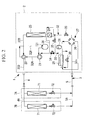
- FIGS. 7 to 10 show refrigerant circuit diagrams of a heat-pump air conditioner according to a third embodiment of the present invention, in which FIG. 7 shows a cooling cycle, FIG. 8 shows a heating cycle, FIG. 9 shows an overload heating cycle, and FIG. 10 shows a defrosting cycle.
- the bridge circuit 27 is omitted, and the gas injection circuit 33 is configured to function only during cooling.
- a hot-gas bypass circuit 53 is connected to the auxiliary heat exchanger 24 having an anti-freezing function provided at the lower part of the outdoor heat exchanger 23.
- the hot-gas bypass circuit 53 is connected, at one end, to the discharge pipe 32A of the compressor 21 and is connected to the auxiliary heat exchanger 24 through a first on-off valve 50 and a check valve 51.
- the other end is connected, via the auxiliary heat exchanger 24, through a second on-off valve 52, to the liquid pipe 32C at a point between the outdoor heat exchanger 23 and the outdoor electric expansion valve 25.
- the above-described hot-gas bypass circuit 53 is provided with a first bypass circuit 56 that branches off from a point between the auxiliary heat exchanger 24 and the check valve 51 and is connected to the intake pipe 32E at the inlet of the accumulator 31 through a third on-off valve 54 and a refrigerant regulating throttle 55, and a second bypass circuit 58 that branches off from a point between the auxiliary heat exchanger 24 and the second on-off valve 52 and is connected to the intake pipe 32E at the inlet of the accumulator 31 through a fourth on-off valve 57 and the refrigerant regulating throttle 55.
- This refrigerant is subjected to heat exchange with the outside air in the auxiliary heat exchanger 24 to be condensed and liquefied, is then merged, in the liquid pipe 32C, with the refrigerant having been condensed in the outdoor heat exchanger 23, passes through the outdoor electric expansion valve 25 (fully open), and flows into the receiver 28.
- the auxiliary heat exchanger 24 is made to function as a condenser during cooling, the heat-pump air conditioner 1 can be operated with high capacity and high efficiency to perform cooling.
- the first on-off valve 50 can be closed to block the hot-gas bypass circuit 53, so that the flow of the hot gas refrigerant into the auxiliary heat exchanger 24 can be stopped. Because this provides substantially the same effect as a reduction in size of the condenser, the condensing performance can be restricted. Therefore, by controlling the condensing pressure to keep the high pressure at a predetermined pressure or more, the cooling operation can be continued.
- the first on-off valve 50 and the fourth on-off valve 57 are closed, and the second on-off valve 52 and the third on-off valve 54 are opened.
- part of the gas-liquid two phase refrigerant having been adiabatically expanded in the outdoor electric expansion valve 25 flows through the second on-off valve 52 into the auxiliary heat exchanger 24, absorbs heat from the outside air, and is vaporized.
- This refrigerant is guided, via the third on-off valve 54 and the refrigerant regulating throttle 55, from the first bypass circuit 56 to the intake pipe 32E at the inlet of the accumulator 31, is merged with the refrigerant vaporized via the outdoor heat exchanger 23, and is then taken into the compressor 21.
- the auxiliary heat exchanger 24 is made to function as an evaporator during heating, the heat-pump air conditioner 1 can be operated with high capacity and high efficiency to perform heating.
- the first on-off valve 50 and the fourth on-off valve 57 are opened, and the second on-off valve 52 and the third on-off valve 54 are closed.
- This refrigerant after releasing heat to the outside air to be condensed in the auxiliary heat exchanger 24, is guided from the fourth on-off valve 57, via the second bypass circuit 58, through the refrigerant regulating throttle 55, to the intake pipe 32E at the inlet of the accumulator 31.
- the first on-off valve 50 and the fourth on-off valve 57 are opened, and the second on-off valve 52 and the third on-off valve 54 are closed.
- part of the high-temperature, high-pressure hot gas refrigerant discharged from the compressor 21 flows from the discharge pipe 32A, via the hot-gas bypass circuit 53, into the auxiliary heat exchanger 24.
- This refrigerant releases heat in the auxiliary heat exchanger 24 and is used to heat the lower part of the outdoor heat exchanger 23 and the drain pan 44 (see FIGS. 5 and 6 ).
- the refrigerant condensed by releasing heat is guided from the fourth on-off valve 57, via the second bypass circuit 58, through the refrigerant regulating throttle 55, to the intake pipe 32E at the inlet of the accumulator 31.
- the auxiliary heat exchanger 24 function as a radiator during defrosting, it can be used to prevent the drain water, resulting from melted frost, from refreezing.
- this embodiment provides the following advantages.
- the economizer effect due to the gas injection not only can the capacity and performance during cooling be improved, but also the auxiliary heat exchanger 24 provided at the lower part of the outdoor heat exchanger 23 can be made to function as a condenser during cooling.
- the cooling capacity can be improved by increasing the condensing performance.
- the function as a condenser can be aborted to restrict the condensing performance during cooling at a low outside-air temperature, it is possible to continue the cooling operation while keeping the high pressure at a predetermined pressure or more.
- the operating range can be expanded.
- the auxiliary heat exchanger 24 can be made to function as an evaporator during heating and can be made to function as a radiator under overload heating conditions, it can be used to improve and adjust the heating capacity.
- the auxiliary heat exchanger 24 can be made to function as a radiator during defrosting, the lower part of the outdoor heat exchanger 23 and the drain pan can be heated and reliably prevented from freezing. Accordingly, it is possible to prevent the outdoor heat exchanger 23 and the drain pan from freezing while maintaining the high performance and high capacity of the heat-pump air conditioner 1.
- the present invention is not limited to the invention according to the above-described embodiments, but may be appropriately modified within a scope not departing from the spirit thereof.
- the heat-pump air conditioner need not necessarily be a multi type, and the present invention can of course be applied to a single-type heat-pump air conditioner having one indoor unit.
- the heat-pump air conditioner is not limited to this, but may be of a multi-outdoor-unit type, in which a plurality of outdoor units 2 are provided in parallel.
- the outdoor unit 2 may be of a type in which a plurality of compressors 21 or a plurality of outdoor heat exchangers 23 and outdoor fans are provided in parallel.
- the gas injection circuit 33 is configured to function only during cooling, the gas injection circuit 33 may be, similarly to the first embodiment, configured to function also during heating.
- the gas injection circuit 33 of a type which uses the intermediate heat exchanger 29 has been described, it may of course be configured to use a gas liquid separator instead of the intermediate heat exchanger 29.
Priority Applications (1)
| Application Number | Priority Date | Filing Date | Title |
|---|---|---|---|
| EP18176668.4A EP3388758A1 (de) | 2007-11-22 | 2008-11-11 | Wärmepumpenklimaanlage |
Applications Claiming Priority (2)
| Application Number | Priority Date | Filing Date | Title |
|---|---|---|---|
| JP2007303420A JP5357418B2 (ja) | 2007-11-22 | 2007-11-22 | ヒートポンプ式空気調和機 |
| PCT/JP2008/070471 WO2009066581A1 (ja) | 2007-11-22 | 2008-11-11 | ヒートポンプ式空気調和機 |
Related Child Applications (1)
| Application Number | Title | Priority Date | Filing Date |
|---|---|---|---|
| EP18176668.4A Division EP3388758A1 (de) | 2007-11-22 | 2008-11-11 | Wärmepumpenklimaanlage |
Publications (2)
| Publication Number | Publication Date |
|---|---|
| EP2211127A1 true EP2211127A1 (de) | 2010-07-28 |
| EP2211127A4 EP2211127A4 (de) | 2017-11-01 |
Family
ID=40667406
Family Applications (2)
| Application Number | Title | Priority Date | Filing Date |
|---|---|---|---|
| EP18176668.4A Withdrawn EP3388758A1 (de) | 2007-11-22 | 2008-11-11 | Wärmepumpenklimaanlage |
| EP08851740.4A Withdrawn EP2211127A4 (de) | 2007-11-22 | 2008-11-11 | Klimaanlage mit wärmepumpe |
Family Applications Before (1)
| Application Number | Title | Priority Date | Filing Date |
|---|---|---|---|
| EP18176668.4A Withdrawn EP3388758A1 (de) | 2007-11-22 | 2008-11-11 | Wärmepumpenklimaanlage |
Country Status (3)
| Country | Link |
|---|---|
| EP (2) | EP3388758A1 (de) |
| JP (1) | JP5357418B2 (de) |
| WO (1) | WO2009066581A1 (de) |
Cited By (4)
| Publication number | Priority date | Publication date | Assignee | Title |
|---|---|---|---|---|
| EP2716998A1 (de) * | 2011-05-23 | 2014-04-09 | Mitsubishi Electric Corporation | Klimaanlage |
| US9003819B2 (en) | 2009-09-30 | 2015-04-14 | Fujitsu General Limited | Heat pump apparatus using supercooling degree to control expansion valve |
| US9822996B2 (en) | 2014-12-01 | 2017-11-21 | David Deng | Additive heat unit for HVAC heat pump system |
| CN110542256A (zh) * | 2019-09-10 | 2019-12-06 | 珠海格力电器股份有限公司 | 防冻控制方法、装置、热泵水系统以及存储介质 |
Families Citing this family (16)
| Publication number | Priority date | Publication date | Assignee | Title |
|---|---|---|---|---|
| JP5554038B2 (ja) * | 2009-09-09 | 2014-07-23 | 三菱重工業株式会社 | 空気調和機のデフロストヒータ制御方法 |
| WO2012014345A1 (ja) * | 2010-07-29 | 2012-02-02 | 三菱電機株式会社 | ヒートポンプ |
| JP2013108729A (ja) * | 2011-11-24 | 2013-06-06 | Daikin Industries Ltd | 空気調和装置 |
| WO2013077136A1 (ja) * | 2011-11-24 | 2013-05-30 | ダイキン工業株式会社 | 空気調和装置 |
| WO2013111177A1 (ja) | 2012-01-24 | 2013-08-01 | 三菱電機株式会社 | 空気調和装置 |
| JP2013189179A (ja) * | 2012-02-15 | 2013-09-26 | Sanden Corp | 車両用空気調和装置 |
| JP2013189180A (ja) * | 2012-02-15 | 2013-09-26 | Sanden Corp | 車両用空気調和装置 |
| JP6351494B2 (ja) * | 2014-12-12 | 2018-07-04 | 日立ジョンソンコントロールズ空調株式会社 | 空気調和機 |
| JP2018516355A (ja) * | 2015-10-27 | 2018-06-21 | 広東美的暖通設備有限公司Gd Midea Heating & Ventilating Equipment Co.,Ltd. | 蒸気噴射増エンタルピー空気調和システム |
| JP6161741B2 (ja) * | 2016-01-20 | 2017-07-12 | 三菱電機株式会社 | 空気調和装置 |
| JP6771302B2 (ja) * | 2016-04-19 | 2020-10-21 | 日立ジョンソンコントロールズ空調株式会社 | 空気調和機 |
| CN106288048B (zh) * | 2016-08-31 | 2019-03-15 | 广东美的制冷设备有限公司 | 除湿机及其控制方法 |
| KR101989753B1 (ko) * | 2018-11-23 | 2019-06-17 | 대성히트펌프 주식회사 | 과냉각도 운전제어와 적정 냉매량 판별 기능을 갖는 브릿지 정류회로방식이 적용된 히트펌프 시스템 및 그 제어방법 |
| CN110497769A (zh) * | 2019-09-23 | 2019-11-26 | 中国科学院理化技术研究所 | 汽车热泵系统及其控制方法 |
| CN110848845B (zh) * | 2019-11-18 | 2024-02-20 | 珠海格力电器股份有限公司 | 一种补气增焓热泵系统、控制方法和空调器 |
| KR20230099313A (ko) | 2021-12-27 | 2023-07-04 | 현대자동차주식회사 | 가스 인젝션 타입의 차량용 열관리 시스템 |
Family Cites Families (18)
| Publication number | Priority date | Publication date | Assignee | Title |
|---|---|---|---|---|
| JPS5318922Y2 (de) * | 1972-11-20 | 1978-05-19 | ||
| JPS563580Y2 (de) * | 1978-03-09 | 1981-01-26 | ||
| JPS58155572U (ja) * | 1982-04-13 | 1983-10-18 | 三洋電機株式会社 | ヒ−トポンプ式空気調和機 |
| JPS608665A (ja) | 1983-06-24 | 1985-01-17 | 松下冷機株式会社 | 暖房専用ヒ−トポンプ式空気調和機 |
| JPS60114666A (ja) | 1983-11-26 | 1985-06-21 | 松下電器産業株式会社 | 空気調和機の凍結防止装置 |
| JPS60205159A (ja) * | 1984-03-29 | 1985-10-16 | 株式会社東芝 | 冷媒加熱式ヒ−トポンプ装置 |
| JPS61101762A (ja) * | 1984-10-25 | 1986-05-20 | 松下電器産業株式会社 | 空冷ヒ−トポンプ式暖房装置 |
| US5056327A (en) * | 1990-02-26 | 1991-10-15 | Heatcraft, Inc. | Hot gas defrost refrigeration system |
| JPH04186074A (ja) * | 1990-11-19 | 1992-07-02 | Matsushita Seiko Co Ltd | 空気調和機 |
| JPH06180164A (ja) * | 1992-12-08 | 1994-06-28 | Mitsubishi Heavy Ind Ltd | 空気調和機 |
| JPH07280378A (ja) * | 1994-04-08 | 1995-10-27 | Mitsubishi Heavy Ind Ltd | ヒートポンプ式空気調和機 |
| JPH08193771A (ja) * | 1995-01-17 | 1996-07-30 | Hitachi Ltd | 冷凍サイクル |
| JP3709477B2 (ja) * | 2000-05-22 | 2005-10-26 | ダイキン工業株式会社 | 空気調和機の冷媒回路 |
| JP2005233551A (ja) * | 2004-02-20 | 2005-09-02 | Mitsubishi Electric Corp | 冷凍サイクル装置 |
| JP2006097992A (ja) | 2004-09-30 | 2006-04-13 | Sharp Corp | 空気調和機 |
| JP4771721B2 (ja) * | 2005-03-16 | 2011-09-14 | 三菱電機株式会社 | 空気調和装置 |
| JP4657087B2 (ja) * | 2005-11-14 | 2011-03-23 | 三洋電機株式会社 | ヒートポンプ式給湯機 |
| JP4725387B2 (ja) * | 2006-03-28 | 2011-07-13 | 三菱電機株式会社 | 空気調和装置 |
-
2007
- 2007-11-22 JP JP2007303420A patent/JP5357418B2/ja active Active
-
2008
- 2008-11-11 EP EP18176668.4A patent/EP3388758A1/de not_active Withdrawn
- 2008-11-11 EP EP08851740.4A patent/EP2211127A4/de not_active Withdrawn
- 2008-11-11 WO PCT/JP2008/070471 patent/WO2009066581A1/ja active Application Filing
Non-Patent Citations (1)
| Title |
|---|
| See references of WO2009066581A1 * |
Cited By (7)
| Publication number | Priority date | Publication date | Assignee | Title |
|---|---|---|---|---|
| US9003819B2 (en) | 2009-09-30 | 2015-04-14 | Fujitsu General Limited | Heat pump apparatus using supercooling degree to control expansion valve |
| EP2716998A1 (de) * | 2011-05-23 | 2014-04-09 | Mitsubishi Electric Corporation | Klimaanlage |
| EP2716998A4 (de) * | 2011-05-23 | 2014-10-22 | Mitsubishi Electric Corp | Klimaanlage |
| US9494348B2 (en) | 2011-05-23 | 2016-11-15 | Mitsubishi Electric Corporation | Air-conditioning apparatus |
| US9822996B2 (en) | 2014-12-01 | 2017-11-21 | David Deng | Additive heat unit for HVAC heat pump system |
| CN110542256A (zh) * | 2019-09-10 | 2019-12-06 | 珠海格力电器股份有限公司 | 防冻控制方法、装置、热泵水系统以及存储介质 |
| CN110542256B (zh) * | 2019-09-10 | 2021-06-01 | 珠海格力电器股份有限公司 | 防冻控制方法、装置、热泵水系统以及存储介质 |
Also Published As
| Publication number | Publication date |
|---|---|
| WO2009066581A1 (ja) | 2009-05-28 |
| EP3388758A1 (de) | 2018-10-17 |
| JP2009127939A (ja) | 2009-06-11 |
| JP5357418B2 (ja) | 2013-12-04 |
| EP2211127A4 (de) | 2017-11-01 |
Similar Documents
| Publication | Publication Date | Title |
|---|---|---|
| EP2211127A1 (de) | Klimaanlage mit wärmepumpe | |
| CN211739592U (zh) | 连续制热的空调系统 | |
| EP3062031B1 (de) | Klimaanlage | |
| JP5595140B2 (ja) | ヒートポンプ式給湯・空調装置 | |
| KR100833441B1 (ko) | 냉동장치 | |
| KR100795291B1 (ko) | 냉동장치 | |
| EP1967801A2 (de) | Heißwassersystem | |
| JP4874223B2 (ja) | 空気調和機 | |
| CN113959010B (zh) | 一拖多制冷制热空调机 | |
| CN107763774A (zh) | 空调制冷循环系统及空调器 | |
| JP2006284035A (ja) | 空気調和装置およびその制御方法 | |
| KR100998139B1 (ko) | 공기 조화 장치 | |
| JPH10160299A (ja) | 冷凍装置 | |
| JP4023387B2 (ja) | 冷凍装置 | |
| CN213089945U (zh) | 一种空调装置 | |
| JP2009293887A (ja) | 冷凍装置 | |
| JP2007127302A (ja) | 冷凍装置 | |
| KR100821729B1 (ko) | 공기 조화 시스템 | |
| KR20220045359A (ko) | 냉난방 멀티 공기조화기 | |
| JP3781340B2 (ja) | 蓄熱式冷凍空調装置 | |
| WO2018037452A1 (ja) | 空気調和装置 | |
| JPH1163709A (ja) | 空気調和機 | |
| CN214501455U (zh) | 空调器 | |
| CN109959180B (zh) | 空调系统及其除霜方法 | |
| JPH11304265A (ja) | 空気調和機 |
Legal Events
| Date | Code | Title | Description |
|---|---|---|---|
| PUAI | Public reference made under article 153(3) epc to a published international application that has entered the european phase |
Free format text: ORIGINAL CODE: 0009012 |
|
| 17P | Request for examination filed |
Effective date: 20100226 |
|
| AK | Designated contracting states |
Kind code of ref document: A1 Designated state(s): AT BE BG CH CY CZ DE DK EE ES FI FR GB GR HR HU IE IS IT LI LT LU LV MC MT NL NO PL PT RO SE SI SK TR |
|
| AX | Request for extension of the european patent |
Extension state: AL BA MK RS |
|
| DAX | Request for extension of the european patent (deleted) | ||
| RA4 | Supplementary search report drawn up and despatched (corrected) |
Effective date: 20171005 |
|
| RIC1 | Information provided on ipc code assigned before grant |
Ipc: F25B 1/10 20060101ALN20170928BHEP Ipc: F25B 13/00 20060101AFI20170928BHEP Ipc: F25B 47/00 20060101ALN20170928BHEP |
|
| RAP1 | Party data changed (applicant data changed or rights of an application transferred) |
Owner name: MITSUBISHI HEAVY INDUSTRIES THERMAL SYSTEMS, LTD. |
|
| 17Q | First examination report despatched |
Effective date: 20180620 |
|
| GRAP | Despatch of communication of intention to grant a patent |
Free format text: ORIGINAL CODE: EPIDOSNIGR1 |
|
| INTG | Intention to grant announced |
Effective date: 20190415 |
|
| STAA | Information on the status of an ep patent application or granted ep patent |
Free format text: STATUS: THE APPLICATION IS DEEMED TO BE WITHDRAWN |
|
| 18D | Application deemed to be withdrawn |
Effective date: 20190827 |