EP2206909A1 - Kolbenvorrichtung für Verbrennungsmotoren - Google Patents
Kolbenvorrichtung für Verbrennungsmotoren Download PDFInfo
- Publication number
- EP2206909A1 EP2206909A1 EP09252847A EP09252847A EP2206909A1 EP 2206909 A1 EP2206909 A1 EP 2206909A1 EP 09252847 A EP09252847 A EP 09252847A EP 09252847 A EP09252847 A EP 09252847A EP 2206909 A1 EP2206909 A1 EP 2206909A1
- Authority
- EP
- European Patent Office
- Prior art keywords
- ring
- compression ring
- tapered surface
- notch
- compression
- Prior art date
- Legal status (The legal status is an assumption and is not a legal conclusion. Google has not performed a legal analysis and makes no representation as to the accuracy of the status listed.)
- Granted
Links
- 238000002485 combustion reaction Methods 0.000 title claims abstract description 14
- 230000006835 compression Effects 0.000 claims abstract description 96
- 238000007906 compression Methods 0.000 claims abstract description 96
- 230000003247 decreasing effect Effects 0.000 claims abstract description 16
- 230000002093 peripheral effect Effects 0.000 claims description 3
- 230000000694 effects Effects 0.000 description 4
- 238000007790 scraping Methods 0.000 description 4
- 230000000630 rising effect Effects 0.000 description 2
Images


Classifications
-
- F—MECHANICAL ENGINEERING; LIGHTING; HEATING; WEAPONS; BLASTING
- F02—COMBUSTION ENGINES; HOT-GAS OR COMBUSTION-PRODUCT ENGINE PLANTS
- F02F—CYLINDERS, PISTONS OR CASINGS, FOR COMBUSTION ENGINES; ARRANGEMENTS OF SEALINGS IN COMBUSTION ENGINES
- F02F5/00—Piston rings, e.g. associated with piston crown
-
- F—MECHANICAL ENGINEERING; LIGHTING; HEATING; WEAPONS; BLASTING
- F16—ENGINEERING ELEMENTS AND UNITS; GENERAL MEASURES FOR PRODUCING AND MAINTAINING EFFECTIVE FUNCTIONING OF MACHINES OR INSTALLATIONS; THERMAL INSULATION IN GENERAL
- F16J—PISTONS; CYLINDERS; SEALINGS
- F16J9/00—Piston-rings, e.g. non-metallic piston-rings, seats therefor; Ring sealings of similar construction
- F16J9/12—Details
- F16J9/14—Joint-closures
-
- F—MECHANICAL ENGINEERING; LIGHTING; HEATING; WEAPONS; BLASTING
- F16—ENGINEERING ELEMENTS AND UNITS; GENERAL MEASURES FOR PRODUCING AND MAINTAINING EFFECTIVE FUNCTIONING OF MACHINES OR INSTALLATIONS; THERMAL INSULATION IN GENERAL
- F16J—PISTONS; CYLINDERS; SEALINGS
- F16J9/00—Piston-rings, e.g. non-metallic piston-rings, seats therefor; Ring sealings of similar construction
- F16J9/12—Details
- F16J9/20—Rings with special cross-section; Oil-scraping rings
Definitions
- the present invention relates to a piston device for internal combustion engines containing compression rings capable of reducing oil consumption during driving at high-speeds and high loads and driving under high-boost conditions.
- the Japanese unexamined utility model application publication No. 5-030624 proposes a compression ring for internal combustion engines.
- the gap between the both ends of the second compression ring is reduced to the utmost to an extent where the ring ends barely avoid coming in contact, and a notch extending from the outer circumference to the inner circumference is formed on the lower surface of at least one of the ends of the second compression ring, and the gap between the ring ends at the notch on the second compression ring is formed larger than the gap between the both ends of the first compression ring.
- 48-21014 proposes a pin 12 provided on the piston 1 for preventing rotation of the ring, and a pair of piston rings 3, 4 including arc-shaped notches formed on the lower surface of the ring ends so as not to interfere with the pin 12.
- the ring 3 is formed as an undercut ring.
- the outer circumferential surfaces are both formed as an axial parallel surface so that oil consumption during driving at high-speeds and high-loads and driving under high-boost conditions is still not always satisfactory.
- the ring disclosed in the Japanese unexamined patent application publication No. 48-21014 contains an arc-shaped notch formed on the lower surface of the ring end so that oil tends to rise upward along the arc-shaped surface.
- An object of the present invention is to reduce oil consumption in a piston device for internal combustion engines during driving at high speeds and high loads and driving under high-boost conditions.
- the piston device for internal combustion engines includes a first compression ring and a second compression ring in an outer circumference of a piston, wherein the second compression ring includes a notch extending from the inner circumference to the outer circumference on a lower surface of at least one of a pair of ends of the ring, and a gap between the ring ends at the notch on the second compression ring is larger than a gap between the ring ends of the first compression ring, and a gap between the ring ends at the section other than the notch on the second compression ring is the same or smaller than the gap between the ring ends of the first compression ring, and the second compression ring contains an outer circumferential surface comprised of a tapered surface decreasing the ring radial thickness towards the upper side, and an axial parallel surface formed below the tapered surface.
- the second compression ring may include a tapered surface (See FIG. 14 through FIG. 19 ) having a taper angle smaller than the taper angle of the above tapered surface, instead of utilizing the axial parallel surface (See FIG. 5, FIG. 6 , FIG. 8, FIG. 9, FIG. 11, and FIG. 12 ).
- the second compression ring may in other words contains an outer circumferential surface comprised of a first tapered surface decreasing the ring radial thickness towards the upper side, and a second tapered surface formed below the first tapered surface and having a taper angle smaller than the taper angle of the first tapered surface.
- the second compression ring may include a tapered surface (See FIG. 20 through FIG. 25 ) decreasing the ring radial thickness towards the lower side, instead of utilizing the axial parallel surface (See FIG. 5, FIG. 6 , FIG. 8, FIG. 9, FIG. 11, and FIG. 12 ).
- the second compression ring may in other words contain an outer circumferential surface comprised of a first tapered surface decreasing the ring radial thickness towards the upper side, and a second tapered surface formed below the first tapered surface and decreasing the ring radial thickness towards the lower side.
- the second compression ring may preferably include a cross sectional shape of undercut including a notch on the lower side of the outer circumference of the ring.
- the notch on the lower surface of the ring end may preferably have a rectangular cross section.
- the peripheral width of the notch on the lower surface of the ring end may be preferably wider along the inner circumference than the outer circumference of the ring.
- the second compression ring contains a notch extending from the inner circumference to the outer circumference on the lower surface of at least one of the ends of the ring; and the gap at the notch on the second compression ring is larger than the gap on the first compression ring, and the gap at the section other than the notch on the second compression ring is the same or smaller than the gap on the first compression ring.
- the blow-by gas flowing into the ring groove escapes from the inner circumferential side of the ring by way of the notch on the lower surface of the ring end to the outer side, so that a rise in pressure at the piston land above the second compression ring can be prevented and therefore the oil can be prevented from rising upwards.
- the second compression ring makes contact with the upper surface of the ring groove of the piston during driving under high boost conditions, the upward rise of oil can be reduced because the gap is small.
- the second compression ring moreover has a tapered surface on the upper section of the ring outer circumference which serves to suppress the oil scraping effect when the ring is rising so that oil consumption can be reduced further.
- the preferred embodiment according to claim 2 is capable of improving the oil scraping effect by way of the undercut.
- the preferred embodiment according to claim 3 suppresses an upward rise of oil, compared to when an arc shape is utilized.
- the preferred embodiment according to claim 4 can prevent an upward rise of oil, and reduce oil consumption further because the blow-by gas can easily enter into the gap during driving at high-speeds and high loads.
- multiple ring grooves 3, 4, and 5 are formed on the outer circumferential surface of a piston 2 that moves back and forth inside a cylinder 1 of an internal combustion engine.
- a first compression ring 6, a second compression ring 7, and a combined oil ring 8 are respectively installed in the ring grooves 3, 4, and 5 in order from the combustion chamber side.
- the first compression ring 6 and the second compression ring 7 possess a compression function, and mainly serve to suppress blow-by gas from the combustion chamber and also render the effect of scraping oil on the cylinder wall.
- the second compression ring 7 contains notches 9 having a rectangular cross section and extending from the inner circumference to the outer circumference on the lower surface of the pair of ends of the ring.
- the gap S1 between the ring ends at the notches 9 on the second compression ring 7 is larger than the gap S between the ring ends of the first compression ring 6 (See FIG. 2 .); and the gap S2 between the ring ends at the section other than the notches 9 on the second compression ring 7 is formed the same or smaller than the gap S between the ring ends of the first compression ring 6.
- the outer circumferential surface 12 includes a tapered surface 10 decreasing the ring radial thickness towards the upper side, and an axial parallel surface 11 formed below the tapered surface 10.
- the tapered surface 10 and the axial parallel surface 11 are formed across the entire circumference of the second compression ring 7.
- the boundary between the tapered surface 10 and the axial parallel surface 11 is positioned at a fixed height from the ring lower surface 7a and below the upper surface 9a of the notch 9, in the circumferential positions other than the vicinity of the notches 9.
- the height of the axial parallel surface 11 rises gradually upward from just before the notch 9 so as not to be split by the notch 9, and reaches a position higher than the upper surface 9a of the notch 9 at the notches 9.
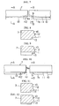
- FIG. 7 through FIG. 9 shows another example of the second compression ring of the present invention.
- the second compression ring 7 of this example differs from the above described second compression ring in the cross sectional shape.
- the second compression ring 7 of this example has a cross sectional shape of undercut including a notch of a step shape on the lower part of the outer circumferential surface 12.
- the second compression ring 7 in this example maintains the relation H1 > H2, when H1 is set as the height of the notches 9 on the ring ends from the ring lower surface 7a, and H2 is set as the height of the notch 13 of the undercut from the ring lower surface 7a.
- H1 is set as the height of the notches 9 on the ring ends from the ring lower surface 7a
- H2 is set as the height of the notch 13 of the undercut from the ring lower surface 7a.
- a large space for oil to collect is formed by the notches 9 on the ring ends which lower the oil pressure when the ring lowers and the oil is scraped downwards, and therefore the upward rise of oil can be prevented.
- FIG. 10 through FIG. 12 shows still another example of the second compression ring of the present invention.
- the second compression ring 7 of this example differs from the second compression ring of the previous example in that the relation is H1 ⁇ H2.
- the boundary between the axial parallel surface 11 and the tapered surface 10 on the outer circumferential surface 12 of the second compression ring 7 is positioned at a fixed height from the ring lower surface 7a and higher than the upper surface 9a of the notch 9, across the entire circumference of the second compression ring 7.
- the second compression ring 7 includes the relation H1 ⁇ H2 when H1 is set as the height of the notches 9 on the ring ends from the ring lower surface 7a, and H2 is set as the height of the notch 13 of the undercut from the ring lower surface 7a.
- the boundary between the axial parallel surface 11 and the tapered surface 10 can be formed across the entire circumference of the second compression ring 7 at a fixed position from the ring lower surface 7a and higher than the upper surface 9a of the notch 9, so that the axial width of the ring that makes contact with the wall of the cylinder 1 in the vicinity of the notches 9 on the ring ends can be made smaller, which allows raising the surface pressure on the ring, and achieves a satisfactory oil scraping effect.
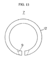
- FIG. 13 is a plan view of the second compression ring 7. As can be seen in the figure, the peripheral width of the notch 9 on the ring end is wider along the inner circumference than the outer circumference. Providing the above described second compression ring 7 with this structure will allow the blow-by gas to easily flow into the gap so that the upward rise of oil can be prevented, and oil consumption can be reduced further.
- the notches are formed on the lower surface of the pair of ends of the second compression ring, however, the present invention is not limited to this structure, and a notch for example may be formed on the lower surface of at least one of the pair of ends of the second compression ring.
- the outer circumferential surface 12 of the second compression ring 7 has the tapered surface 10 decreasing the ring radial thickness towards the upper side, and the axial parallel surface 11 formed below the tapered surface 10, however, the present invention is not limited to this structure.
- the outer circumferential surface 12 of the second compression ring 7 may for example have a first tapered surface 10 decreasing the ring radial thickness towards the upper side, and a second tapered surface 14 formed below the first tapered surface 10 and having a taper angle smaller than the first tapered surface 10 (See FIG. 14 through FIG. 19 ).
- the outer circumferential surface 12 of the second compression ring 7 may also have a first tapered surface 10 decreasing the ring radial thickness towards the upper side, and a second tapered surface 15 formed below the first tapered surface 10 and decreasing the ring radial thickness towards the lower side (See FIG. 20 through FIG. 25 ).
Applications Claiming Priority (1)
| Application Number | Priority Date | Filing Date | Title |
|---|---|---|---|
| JP2008329355A JP5106376B2 (ja) | 2008-12-25 | 2008-12-25 | 内燃機関用ピストン装置 |
Publications (2)
| Publication Number | Publication Date |
|---|---|
| EP2206909A1 true EP2206909A1 (de) | 2010-07-14 |
| EP2206909B1 EP2206909B1 (de) | 2015-05-27 |
Family
ID=42062439
Family Applications (1)
| Application Number | Title | Priority Date | Filing Date |
|---|---|---|---|
| EP09252847.0A Active EP2206909B1 (de) | 2008-12-25 | 2009-12-21 | Kolbenvorrichtung für Verbrennungsmotoren |
Country Status (4)
| Country | Link |
|---|---|
| US (1) | US8365696B2 (de) |
| EP (1) | EP2206909B1 (de) |
| JP (1) | JP5106376B2 (de) |
| CN (1) | CN101761416B (de) |
Cited By (5)
| Publication number | Priority date | Publication date | Assignee | Title |
|---|---|---|---|---|
| DE102013009645A1 (de) * | 2013-06-08 | 2014-12-11 | Federal-Mogul Burscheid Gmbh | Kolbenring |
| DE102015009587A1 (de) | 2015-07-24 | 2017-01-26 | Federal-Mogul Burscheid Gmbh | Kompressionskolbenring |
| EP3546805A1 (de) * | 2018-03-28 | 2019-10-02 | Federal-Mogul Göteborg AB | Kolbenring |
| EP3421846B1 (de) | 2016-02-26 | 2020-11-18 | Kabushiki Kaisha Riken | Kolbenring |
| WO2022233481A1 (de) * | 2021-05-04 | 2022-11-10 | Federal-Mogul Burscheid Gmbh | Kolbenring mit variabler druckentlastung |
Families Citing this family (16)
| Publication number | Priority date | Publication date | Assignee | Title |
|---|---|---|---|---|
| BRPI0605175B1 (pt) * | 2006-12-05 | 2020-01-21 | Mahle Metal Leve S/A | anel de pistão para motores de combustão interna |
| US9542833B2 (en) | 2009-09-10 | 2017-01-10 | Traxxas Lp | Automatic determination of radio control unit configuration parameter settings |
| DE102011010656A1 (de) * | 2011-02-09 | 2012-08-09 | Federal-Mogul Burscheid Gmbh | Kolbenring |
| US9808730B2 (en) | 2011-10-31 | 2017-11-07 | Traxxas Lp | Multi-function electronic device-enabled transmit controller |
| CN103452691A (zh) * | 2012-05-30 | 2013-12-18 | 重庆长安汽车股份有限公司 | 一种汽车增压发动机的防窜漏活塞环组 |
| WO2014043666A1 (en) * | 2012-09-17 | 2014-03-20 | Meacham G B Kirby | Reduced friction piston rings |
| US20150240943A1 (en) * | 2012-09-28 | 2015-08-27 | G.B. Kirby Meacham | Reduced friction oil control piston rings |
| DE102013206399A1 (de) * | 2013-04-11 | 2014-10-16 | Federal-Mogul Friedberg Gmbh | Kolbenring mit periodisch variierender Laufflächenbreite |
| KR20160042036A (ko) * | 2013-08-07 | 2016-04-18 | 페더럴-모걸 코오포레이숀 | 피스톤 링 |
| DE102014003149A1 (de) * | 2014-03-04 | 2015-09-10 | Federal-Mogul Burscheid Gmbh | Ölabstreifkolbenring und Verfahren zur Herstellung eines Ölabstreifkolbenrings |
| JP6314015B2 (ja) * | 2014-03-31 | 2018-04-18 | 日本ピストンリング株式会社 | ピストンとピストンリングの組合せ |
| CN104314700A (zh) * | 2014-10-13 | 2015-01-28 | 重庆长安汽车股份有限公司 | 一种发动机活塞环 |
| WO2018061222A1 (ja) * | 2016-09-30 | 2018-04-05 | Tpr株式会社 | シールリング |
| DE102017100173A1 (de) * | 2017-01-05 | 2018-07-05 | Federal-Mogul Burscheid Gmbh | Kolbenring mit gestufter Lauffläche |
| JP6702537B2 (ja) * | 2018-04-27 | 2020-06-03 | Tpr株式会社 | コンプレッションリング及び内燃機関の組み立て方法 |
| US11674595B2 (en) * | 2020-12-14 | 2023-06-13 | Caterpillar Inc. | Scraper ring for a piston |
Citations (7)
| Publication number | Priority date | Publication date | Assignee | Title |
|---|---|---|---|---|
| US1560307A (en) * | 1925-07-08 | 1925-11-03 | Dock J Peeler | Piston |
| GB502695A (en) * | 1937-09-29 | 1939-03-23 | Vauxhall Motors Ltd | Improved piston rings for internal combustion engines |
| FR2568313A1 (fr) * | 1984-07-28 | 1986-01-31 | Man B & W Diesel Gmbh | Piston de profil special et son jeu de segments |
| GB2164418A (en) * | 1984-09-10 | 1986-03-19 | Nippon Piston Ring Co Ltd | Piston-ring combination |
| US4848212A (en) * | 1986-04-24 | 1989-07-18 | Mazda Motor Corporation | Internal combustion engine piston with two compression rings having reduced oil consumption |
| JPH0530624A (ja) * | 1991-07-15 | 1993-02-05 | Nikken Sekkei Ltd | フリーアクセスフロア |
| JPH0530624U (ja) | 1991-09-26 | 1993-04-23 | 株式会社リケン | 内燃機関用圧力リング |
Family Cites Families (20)
| Publication number | Priority date | Publication date | Assignee | Title |
|---|---|---|---|---|
| US1365640A (en) * | 1919-03-28 | 1921-01-11 | Copp Ralph | Piston-ring |
| US1481167A (en) * | 1922-03-30 | 1924-01-15 | Malcolm M White | Piston ring |
| DE2358372A1 (de) | 1973-11-23 | 1975-05-28 | Rheinische Braunkohlenw Ag | Verfahren zur nutzung der waermeenergie eines hochtemperatur-kernreaktors mittels vergasen von festen, kohlenstoffhaltigen materialien |
| JPS5122977Y2 (de) * | 1973-12-12 | 1976-06-14 | ||
| JPS5516127Y2 (de) * | 1974-02-12 | 1980-04-15 | ||
| JPS5832153A (ja) | 1981-08-20 | 1983-02-25 | Teijin Ltd | 酸素センサ− |
| JPS5832153U (ja) * | 1981-08-27 | 1983-03-02 | いすゞ自動車株式会社 | ピストンリング |
| JPS632848A (ja) | 1986-06-19 | 1988-01-07 | ダイソー株式会社 | 耐衝撃性の改善されたレジンコンクリ−ト |
| JPS632848U (de) * | 1986-06-23 | 1988-01-09 | ||
| US5241748A (en) * | 1991-06-27 | 1993-09-07 | Teikoku Piston Ring Co., Ltd. | Method for manufacturing a compression ring |
| JPH06137428A (ja) * | 1992-10-27 | 1994-05-17 | Riken Corp | 内燃機関用圧力リング |
| DE4327621B4 (de) * | 1993-08-17 | 2009-04-09 | Mahle Gmbh | Kolbenringnutgestaltung für Kolben von Verbrennungsmotoren |
| EP0797743A1 (de) * | 1994-11-17 | 1997-10-01 | Hermann Meckes | Kolbenringdichtung |
| CN2233988Y (zh) * | 1995-09-27 | 1996-08-28 | 王保东 | 自动润滑调隙活塞环 |
| JPH10252891A (ja) * | 1997-03-14 | 1998-09-22 | Nippon Piston Ring Co Ltd | アルミシリンダ用第二圧力リングおよびその製造方法 |
| JPH11264468A (ja) * | 1998-03-17 | 1999-09-28 | Nippon Piston Ring Co Ltd | ピストンリング及びその組合せ |
| JP3607120B2 (ja) * | 1999-05-28 | 2005-01-05 | ダイハツ工業株式会社 | 内燃機関用ピストンにおける気密装置 |
| CN2380703Y (zh) * | 1999-06-08 | 2000-05-31 | 朱志鸿 | 高效组合式活塞环 |
| JP2003113940A (ja) * | 2001-08-02 | 2003-04-18 | Riken Corp | スチール製ピストンリング |
| JP2005264978A (ja) * | 2004-03-16 | 2005-09-29 | Toyota Motor Corp | 圧力リング |
-
2008
- 2008-12-25 JP JP2008329355A patent/JP5106376B2/ja active Active
-
2009
- 2009-12-18 US US12/641,706 patent/US8365696B2/en active Active
- 2009-12-21 EP EP09252847.0A patent/EP2206909B1/de active Active
- 2009-12-25 CN CN200910262657.4A patent/CN101761416B/zh active Active
Patent Citations (7)
| Publication number | Priority date | Publication date | Assignee | Title |
|---|---|---|---|---|
| US1560307A (en) * | 1925-07-08 | 1925-11-03 | Dock J Peeler | Piston |
| GB502695A (en) * | 1937-09-29 | 1939-03-23 | Vauxhall Motors Ltd | Improved piston rings for internal combustion engines |
| FR2568313A1 (fr) * | 1984-07-28 | 1986-01-31 | Man B & W Diesel Gmbh | Piston de profil special et son jeu de segments |
| GB2164418A (en) * | 1984-09-10 | 1986-03-19 | Nippon Piston Ring Co Ltd | Piston-ring combination |
| US4848212A (en) * | 1986-04-24 | 1989-07-18 | Mazda Motor Corporation | Internal combustion engine piston with two compression rings having reduced oil consumption |
| JPH0530624A (ja) * | 1991-07-15 | 1993-02-05 | Nikken Sekkei Ltd | フリーアクセスフロア |
| JPH0530624U (ja) | 1991-09-26 | 1993-04-23 | 株式会社リケン | 内燃機関用圧力リング |
Cited By (11)
| Publication number | Priority date | Publication date | Assignee | Title |
|---|---|---|---|---|
| DE102013009645A1 (de) * | 2013-06-08 | 2014-12-11 | Federal-Mogul Burscheid Gmbh | Kolbenring |
| DE102015009587A1 (de) | 2015-07-24 | 2017-01-26 | Federal-Mogul Burscheid Gmbh | Kompressionskolbenring |
| WO2017016537A1 (de) | 2015-07-24 | 2017-02-02 | Federal-Mogul Burscheid Gmbh | Kompressionskolbenring |
| DE102015009587B4 (de) | 2015-07-24 | 2018-11-22 | Federal-Mogul Burscheid Gmbh | Kompressionskolbenring |
| EP3325856B1 (de) | 2015-07-24 | 2019-07-24 | Federal-Mogul Burscheid GmbH | Kompressionskolbenring |
| RU2696156C2 (ru) * | 2015-07-24 | 2019-07-31 | Федерал-Моугал Буршайд Гмбх | Компрессионное поршневое кольцо |
| EP3421846B1 (de) | 2016-02-26 | 2020-11-18 | Kabushiki Kaisha Riken | Kolbenring |
| EP3546805A1 (de) * | 2018-03-28 | 2019-10-02 | Federal-Mogul Göteborg AB | Kolbenring |
| WO2019185546A1 (en) * | 2018-03-28 | 2019-10-03 | Federal-Mogul Göteborg Ab | A piston ring |
| KR20200136969A (ko) * | 2018-03-28 | 2020-12-08 | 페더럴-모굴 예테보리 에이비 | 피스톤 링 |
| WO2022233481A1 (de) * | 2021-05-04 | 2022-11-10 | Federal-Mogul Burscheid Gmbh | Kolbenring mit variabler druckentlastung |
Also Published As
| Publication number | Publication date |
|---|---|
| CN101761416A (zh) | 2010-06-30 |
| US20100162987A1 (en) | 2010-07-01 |
| US8365696B2 (en) | 2013-02-05 |
| EP2206909B1 (de) | 2015-05-27 |
| JP5106376B2 (ja) | 2012-12-26 |
| JP2010151013A (ja) | 2010-07-08 |
| CN101761416B (zh) | 2014-03-05 |
Similar Documents
| Publication | Publication Date | Title |
|---|---|---|
| EP2206909B1 (de) | Kolbenvorrichtung für Verbrennungsmotoren | |
| CN101839187B (zh) | 内燃机活塞 | |
| WO2007088847A1 (ja) | 3ピースオイルリング及び3ピースオイルリングとピストンとの組合せ | |
| EP1719901A1 (de) | Kolbenvorrichtung für verbrennungsmotor | |
| JP2006144700A (ja) | 内燃機関用エンジンのピストン及び内燃機関用エンジンのピストンとピストンリングの組合せ | |
| EP2765318A1 (de) | Gleitlager | |
| JP5893946B2 (ja) | エンジン | |
| US9086030B2 (en) | Piston for internal combustion engine | |
| JP2010164012A (ja) | 内燃機関用ピストン | |
| JP2016223583A (ja) | 内燃機関 | |
| JP4254634B2 (ja) | 内燃機関用ピストン | |
| CN103119311A (zh) | 内燃发动机曲轴的曲轴支承 | |
| JP2007170455A (ja) | 組合せオイルリング | |
| JP2010133321A (ja) | シリンダライナの潤滑構造 | |
| JP2002013441A (ja) | 内燃機関のピストン | |
| JP3120918B2 (ja) | 内燃機関用ピストン | |
| JP5267936B2 (ja) | 内燃機関のピストン | |
| WO2017130457A1 (ja) | 連接棒およびこれを備えたクロスヘッド型エンジン | |
| KR102429575B1 (ko) | 피스톤 | |
| JP2006250245A (ja) | ピストンリング | |
| JPH11325248A (ja) | 内燃機関のピストン | |
| KR102539763B1 (ko) | 피스톤 링의 조합체 및 피스톤과 피스톤 링의 조합 구조체 | |
| JP3065118B2 (ja) | 内燃機関用トランクピストン | |
| CN211598841U (zh) | 发动机机体及具有其的发动机 | |
| CN108730065B (zh) | 压力环 |
Legal Events
| Date | Code | Title | Description |
|---|---|---|---|
| PUAI | Public reference made under article 153(3) epc to a published international application that has entered the european phase |
Free format text: ORIGINAL CODE: 0009012 |
|
| AK | Designated contracting states |
Kind code of ref document: A1 Designated state(s): AT BE BG CH CY CZ DE DK EE ES FI FR GB GR HR HU IE IS IT LI LT LU LV MC MK MT NL NO PL PT RO SE SI SK SM TR |
|
| AX | Request for extension of the european patent |
Extension state: AL BA RS |
|
| 17P | Request for examination filed |
Effective date: 20101102 |
|
| GRAP | Despatch of communication of intention to grant a patent |
Free format text: ORIGINAL CODE: EPIDOSNIGR1 |
|
| INTG | Intention to grant announced |
Effective date: 20141208 |
|
| RIN1 | Information on inventor provided before grant (corrected) |
Inventor name: ISHIDA, MASAO |
|
| GRAS | Grant fee paid |
Free format text: ORIGINAL CODE: EPIDOSNIGR3 |
|
| RAP1 | Party data changed (applicant data changed or rights of an application transferred) |
Owner name: TPR CO., LTD. |
|
| GRAA | (expected) grant |
Free format text: ORIGINAL CODE: 0009210 |
|
| AK | Designated contracting states |
Kind code of ref document: B1 Designated state(s): AT BE BG CH CY CZ DE DK EE ES FI FR GB GR HR HU IE IS IT LI LT LU LV MC MK MT NL NO PL PT RO SE SI SK SM TR |
|
| REG | Reference to a national code |
Ref country code: GB Ref legal event code: FG4D |
|
| REG | Reference to a national code |
Ref country code: CH Ref legal event code: EP |
|
| REG | Reference to a national code |
Ref country code: AT Ref legal event code: REF Ref document number: 728998 Country of ref document: AT Kind code of ref document: T Effective date: 20150615 |
|
| REG | Reference to a national code |
Ref country code: IE Ref legal event code: FG4D |
|
| REG | Reference to a national code |
Ref country code: DE Ref legal event code: R096 Ref document number: 602009031410 Country of ref document: DE Effective date: 20150702 |
|
| REG | Reference to a national code |
Ref country code: AT Ref legal event code: MK05 Ref document number: 728998 Country of ref document: AT Kind code of ref document: T Effective date: 20150527 |
|
| REG | Reference to a national code |
Ref country code: LT Ref legal event code: MG4D |
|
| PG25 | Lapsed in a contracting state [announced via postgrant information from national office to epo] |
Ref country code: PT Free format text: LAPSE BECAUSE OF FAILURE TO SUBMIT A TRANSLATION OF THE DESCRIPTION OR TO PAY THE FEE WITHIN THE PRESCRIBED TIME-LIMIT Effective date: 20150928 Ref country code: FI Free format text: LAPSE BECAUSE OF FAILURE TO SUBMIT A TRANSLATION OF THE DESCRIPTION OR TO PAY THE FEE WITHIN THE PRESCRIBED TIME-LIMIT Effective date: 20150527 Ref country code: LT Free format text: LAPSE BECAUSE OF FAILURE TO SUBMIT A TRANSLATION OF THE DESCRIPTION OR TO PAY THE FEE WITHIN THE PRESCRIBED TIME-LIMIT Effective date: 20150527 Ref country code: ES Free format text: LAPSE BECAUSE OF FAILURE TO SUBMIT A TRANSLATION OF THE DESCRIPTION OR TO PAY THE FEE WITHIN THE PRESCRIBED TIME-LIMIT Effective date: 20150527 Ref country code: NO Free format text: LAPSE BECAUSE OF FAILURE TO SUBMIT A TRANSLATION OF THE DESCRIPTION OR TO PAY THE FEE WITHIN THE PRESCRIBED TIME-LIMIT Effective date: 20150827 Ref country code: HR Free format text: LAPSE BECAUSE OF FAILURE TO SUBMIT A TRANSLATION OF THE DESCRIPTION OR TO PAY THE FEE WITHIN THE PRESCRIBED TIME-LIMIT Effective date: 20150527 |
|
| REG | Reference to a national code |
Ref country code: NL Ref legal event code: MP Effective date: 20150527 |
|
| PG25 | Lapsed in a contracting state [announced via postgrant information from national office to epo] |
Ref country code: AT Free format text: LAPSE BECAUSE OF FAILURE TO SUBMIT A TRANSLATION OF THE DESCRIPTION OR TO PAY THE FEE WITHIN THE PRESCRIBED TIME-LIMIT Effective date: 20150527 Ref country code: IS Free format text: LAPSE BECAUSE OF FAILURE TO SUBMIT A TRANSLATION OF THE DESCRIPTION OR TO PAY THE FEE WITHIN THE PRESCRIBED TIME-LIMIT Effective date: 20150927 Ref country code: LV Free format text: LAPSE BECAUSE OF FAILURE TO SUBMIT A TRANSLATION OF THE DESCRIPTION OR TO PAY THE FEE WITHIN THE PRESCRIBED TIME-LIMIT Effective date: 20150527 Ref country code: GR Free format text: LAPSE BECAUSE OF FAILURE TO SUBMIT A TRANSLATION OF THE DESCRIPTION OR TO PAY THE FEE WITHIN THE PRESCRIBED TIME-LIMIT Effective date: 20150828 Ref country code: BG Free format text: LAPSE BECAUSE OF FAILURE TO SUBMIT A TRANSLATION OF THE DESCRIPTION OR TO PAY THE FEE WITHIN THE PRESCRIBED TIME-LIMIT Effective date: 20150827 |
|
| PG25 | Lapsed in a contracting state [announced via postgrant information from national office to epo] |
Ref country code: EE Free format text: LAPSE BECAUSE OF FAILURE TO SUBMIT A TRANSLATION OF THE DESCRIPTION OR TO PAY THE FEE WITHIN THE PRESCRIBED TIME-LIMIT Effective date: 20150527 Ref country code: DK Free format text: LAPSE BECAUSE OF FAILURE TO SUBMIT A TRANSLATION OF THE DESCRIPTION OR TO PAY THE FEE WITHIN THE PRESCRIBED TIME-LIMIT Effective date: 20150527 |
|
| PG25 | Lapsed in a contracting state [announced via postgrant information from national office to epo] |
Ref country code: SK Free format text: LAPSE BECAUSE OF FAILURE TO SUBMIT A TRANSLATION OF THE DESCRIPTION OR TO PAY THE FEE WITHIN THE PRESCRIBED TIME-LIMIT Effective date: 20150527 Ref country code: RO Free format text: LAPSE BECAUSE OF NON-PAYMENT OF DUE FEES Effective date: 20150527 Ref country code: PL Free format text: LAPSE BECAUSE OF FAILURE TO SUBMIT A TRANSLATION OF THE DESCRIPTION OR TO PAY THE FEE WITHIN THE PRESCRIBED TIME-LIMIT Effective date: 20150527 Ref country code: CZ Free format text: LAPSE BECAUSE OF FAILURE TO SUBMIT A TRANSLATION OF THE DESCRIPTION OR TO PAY THE FEE WITHIN THE PRESCRIBED TIME-LIMIT Effective date: 20150527 |
|
| REG | Reference to a national code |
Ref country code: DE Ref legal event code: R097 Ref document number: 602009031410 Country of ref document: DE |
|
| PLBE | No opposition filed within time limit |
Free format text: ORIGINAL CODE: 0009261 |
|
| STAA | Information on the status of an ep patent application or granted ep patent |
Free format text: STATUS: NO OPPOSITION FILED WITHIN TIME LIMIT |
|
| PG25 | Lapsed in a contracting state [announced via postgrant information from national office to epo] |
Ref country code: IT Free format text: LAPSE BECAUSE OF FAILURE TO SUBMIT A TRANSLATION OF THE DESCRIPTION OR TO PAY THE FEE WITHIN THE PRESCRIBED TIME-LIMIT Effective date: 20150527 |
|
| 26N | No opposition filed |
Effective date: 20160301 |
|
| PG25 | Lapsed in a contracting state [announced via postgrant information from national office to epo] |
Ref country code: SI Free format text: LAPSE BECAUSE OF FAILURE TO SUBMIT A TRANSLATION OF THE DESCRIPTION OR TO PAY THE FEE WITHIN THE PRESCRIBED TIME-LIMIT Effective date: 20150527 Ref country code: BE Free format text: LAPSE BECAUSE OF NON-PAYMENT OF DUE FEES Effective date: 20151231 |
|
| PG25 | Lapsed in a contracting state [announced via postgrant information from national office to epo] |
Ref country code: MC Free format text: LAPSE BECAUSE OF FAILURE TO SUBMIT A TRANSLATION OF THE DESCRIPTION OR TO PAY THE FEE WITHIN THE PRESCRIBED TIME-LIMIT Effective date: 20150527 Ref country code: LU Free format text: LAPSE BECAUSE OF FAILURE TO SUBMIT A TRANSLATION OF THE DESCRIPTION OR TO PAY THE FEE WITHIN THE PRESCRIBED TIME-LIMIT Effective date: 20151221 |
|
| REG | Reference to a national code |
Ref country code: CH Ref legal event code: PL |
|
| GBPC | Gb: european patent ceased through non-payment of renewal fee |
Effective date: 20151221 |
|
| PG25 | Lapsed in a contracting state [announced via postgrant information from national office to epo] |
Ref country code: BE Free format text: LAPSE BECAUSE OF FAILURE TO SUBMIT A TRANSLATION OF THE DESCRIPTION OR TO PAY THE FEE WITHIN THE PRESCRIBED TIME-LIMIT Effective date: 20150527 |
|
| REG | Reference to a national code |
Ref country code: IE Ref legal event code: MM4A |
|
| REG | Reference to a national code |
Ref country code: FR Ref legal event code: ST Effective date: 20160831 |
|
| PG25 | Lapsed in a contracting state [announced via postgrant information from national office to epo] |
Ref country code: LI Free format text: LAPSE BECAUSE OF NON-PAYMENT OF DUE FEES Effective date: 20151231 Ref country code: IE Free format text: LAPSE BECAUSE OF NON-PAYMENT OF DUE FEES Effective date: 20151221 Ref country code: CH Free format text: LAPSE BECAUSE OF NON-PAYMENT OF DUE FEES Effective date: 20151231 Ref country code: GB Free format text: LAPSE BECAUSE OF NON-PAYMENT OF DUE FEES Effective date: 20151221 |
|
| PG25 | Lapsed in a contracting state [announced via postgrant information from national office to epo] |
Ref country code: FR Free format text: LAPSE BECAUSE OF NON-PAYMENT OF DUE FEES Effective date: 20151231 |
|
| PG25 | Lapsed in a contracting state [announced via postgrant information from national office to epo] |
Ref country code: HU Free format text: LAPSE BECAUSE OF FAILURE TO SUBMIT A TRANSLATION OF THE DESCRIPTION OR TO PAY THE FEE WITHIN THE PRESCRIBED TIME-LIMIT; INVALID AB INITIO Effective date: 20091221 Ref country code: SM Free format text: LAPSE BECAUSE OF FAILURE TO SUBMIT A TRANSLATION OF THE DESCRIPTION OR TO PAY THE FEE WITHIN THE PRESCRIBED TIME-LIMIT Effective date: 20150527 |
|
| PG25 | Lapsed in a contracting state [announced via postgrant information from national office to epo] |
Ref country code: NL Free format text: LAPSE BECAUSE OF FAILURE TO SUBMIT A TRANSLATION OF THE DESCRIPTION OR TO PAY THE FEE WITHIN THE PRESCRIBED TIME-LIMIT Effective date: 20150527 Ref country code: SE Free format text: LAPSE BECAUSE OF FAILURE TO SUBMIT A TRANSLATION OF THE DESCRIPTION OR TO PAY THE FEE WITHIN THE PRESCRIBED TIME-LIMIT Effective date: 20150527 Ref country code: CY Free format text: LAPSE BECAUSE OF FAILURE TO SUBMIT A TRANSLATION OF THE DESCRIPTION OR TO PAY THE FEE WITHIN THE PRESCRIBED TIME-LIMIT Effective date: 20150527 |
|
| PG25 | Lapsed in a contracting state [announced via postgrant information from national office to epo] |
Ref country code: MT Free format text: LAPSE BECAUSE OF FAILURE TO SUBMIT A TRANSLATION OF THE DESCRIPTION OR TO PAY THE FEE WITHIN THE PRESCRIBED TIME-LIMIT Effective date: 20150527 Ref country code: TR Free format text: LAPSE BECAUSE OF FAILURE TO SUBMIT A TRANSLATION OF THE DESCRIPTION OR TO PAY THE FEE WITHIN THE PRESCRIBED TIME-LIMIT Effective date: 20150527 |
|
| PG25 | Lapsed in a contracting state [announced via postgrant information from national office to epo] |
Ref country code: MK Free format text: LAPSE BECAUSE OF FAILURE TO SUBMIT A TRANSLATION OF THE DESCRIPTION OR TO PAY THE FEE WITHIN THE PRESCRIBED TIME-LIMIT Effective date: 20150527 |
|
| REG | Reference to a national code |
Ref country code: DE Ref legal event code: R082 Ref document number: 602009031410 Country of ref document: DE |
|
| PGFP | Annual fee paid to national office [announced via postgrant information from national office to epo] |
Ref country code: DE Payment date: 20231214 Year of fee payment: 15 |