EP2202130B1 - Dispositif de direction pour vehicule - Google Patents
Dispositif de direction pour vehicule Download PDFInfo
- Publication number
- EP2202130B1 EP2202130B1 EP08841871A EP08841871A EP2202130B1 EP 2202130 B1 EP2202130 B1 EP 2202130B1 EP 08841871 A EP08841871 A EP 08841871A EP 08841871 A EP08841871 A EP 08841871A EP 2202130 B1 EP2202130 B1 EP 2202130B1
- Authority
- EP
- European Patent Office
- Prior art keywords
- bearing
- shaft
- section
- convex
- rotor
- Prior art date
- Legal status (The legal status is an assumption and is not a legal conclusion. Google has not performed a legal analysis and makes no representation as to the accuracy of the status listed.)
- Not-in-force
Links
Images


Classifications
-
- B—PERFORMING OPERATIONS; TRANSPORTING
- B62—LAND VEHICLES FOR TRAVELLING OTHERWISE THAN ON RAILS
- B62D—MOTOR VEHICLES; TRAILERS
- B62D5/00—Power-assisted or power-driven steering
- B62D5/04—Power-assisted or power-driven steering electrical, e.g. using an electric servo-motor connected to, or forming part of, the steering gear
- B62D5/0409—Electric motor acting on the steering column
-
- B—PERFORMING OPERATIONS; TRANSPORTING
- B62—LAND VEHICLES FOR TRAVELLING OTHERWISE THAN ON RAILS
- B62D—MOTOR VEHICLES; TRAILERS
- B62D5/00—Power-assisted or power-driven steering
- B62D5/008—Changing the transfer ratio between the steering wheel and the steering gear by variable supply of energy, e.g. by using a superposition gear
-
- F—MECHANICAL ENGINEERING; LIGHTING; HEATING; WEAPONS; BLASTING
- F16—ENGINEERING ELEMENTS AND UNITS; GENERAL MEASURES FOR PRODUCING AND MAINTAINING EFFECTIVE FUNCTIONING OF MACHINES OR INSTALLATIONS; THERMAL INSULATION IN GENERAL
- F16H—GEARING
- F16H1/00—Toothed gearings for conveying rotary motion
- F16H1/28—Toothed gearings for conveying rotary motion with gears having orbital motion
- F16H1/32—Toothed gearings for conveying rotary motion with gears having orbital motion in which the central axis of the gearing lies inside the periphery of an orbital gear
- F16H1/321—Toothed gearings for conveying rotary motion with gears having orbital motion in which the central axis of the gearing lies inside the periphery of an orbital gear the orbital gear being nutating
Definitions
- the present invention relates to a motor vehicle steering system including a transmission ratio variable mechanism capable of changing a transmission ratio of a turning angle of steered wheels to a steering angle of a steering member.
- the transmission ratio variable mechanism of the motor vehicle steering system in Patent Document 1 is provided with a wave gear mechanism, in which a wave generator, a flexspline, and a circular spline are lined up in a radial direction of a steering shaft.
- the transmission ratio variable mechanism arranged in according to the Patent Document 2 is provided with a first toothed gear of which the rotation is restrained by the upper steering shaft, a fourth toothed gear of which the rotation is restrained by the lower steering shaft, and a swinging toothed gear having a rotational axis inclined to rotation axes of the first and fourth toothed gears.
- a first toothed gear of which the rotation is restrained by the upper steering shaft a fourth toothed gear of which the rotation is restrained by the lower steering shaft, and a swinging toothed gear having a rotational axis inclined to rotation axes of the first and fourth toothed gears.
- At the both ends of an outer race, that has toothed gear sections, of the swinging toothed gear there are formed second and third toothed gears, and the second toothed gear is meshed with the first toothed gear and the third toothed gear is meshed with the fourth toothed gear.
- Patent Document 4 relates to a motor vehicle steering system comprising a differential drive, said differential drive having a carrier structure, a drive shaft with a shaft end facing the differential drive, an output unit with a shaft end facing the differential drive, and an auxiliary drive comprising a stator and a rotor.
- the aim of Patent Document 4 is to simplify the structure of one such differential drive as much as possible.
- Patent Document 1 Japanese Unexamined Patent Publication No. 2007-125939
- Patent Document 2 Japanese Unexamined Patent Publication No. 2006-82718
- Patent Document 3 Japanese Unexamined Patent Publication No. 2007-170624
- Patent Document 4 DE 10 2004 052 562
- the wave generator, the flexspline, and the circular spline are lined up in a radial direction of the steering shaft, and the wave generator is in the form of an oblong circle, thus long in a longer axis direction.
- the transmission ratio variable mechanism becomes large in the radial direction of the steering shaft.
- An object thereof is to provide a motor vehicle steering system capable of reducing the size of a transmission ratio variable mechanism, increasing the rigidity of supports relating to the transmission ratio variable mechanism, and decreasing a drive sound.
- a motor vehicle steering system of the present invention includes a transmission ratio variable mechanism (5) capable of changing a transmission ratio ( ⁇ 2/ ⁇ 1) of a turning angle ( ⁇ 2) of steered wheels (4L, 4R) relative to a steering angle ( ⁇ 1) of a steering member (2) and a steering-assist-force imparting mechanism (19) for imparting a steering assist force.
- the transmission ratio variable mechanism (5) comprises an input member (20) and an output member (22) capable of rotation about a first axis (A), a first bearing ring (391), having first and second end surfaces (71, 73), for differentially rotatably coupling the input member (20) and the output member (22), a second bearing ring (392) for rotatably supporting the first bearing ring (391) via a rolling element (393), and an actuator (23) capable of rotation-driving the second bearing ring (392).
- a second axis (B) being a center line of the first bearing ring (391) and the second bearing ring (392) is inclined to the first axis (A).
- the input member (20) and the output member (22) respectively have power transmission surfaces (70, 72) opposite the first and second end surfaces (71, 73) of the first bearing ring (391).
- a first concavo-convex engaging section (64) and a second concavo-convex engaging section (67) are arranged for power-transmittably engaging each end surface (71, 73) of the first bearing ring (391) and the power transmission surfaces (70, 72) corresponding to the end surfaces (71, 73).
- the first concavo-convex engaging section (64) and the second concavo-convex engaging section (67) include convex portions (65, 68; 65A) arranged on each end surface (71, 73) or on the power transmission surface (70, 72) corresponding to the end surfaces, and concave portions (66, 69; 66A; 66B) arranged on an alternate surface and engaged with the convex portions.
- Output of the transmission ratio variable mechanism (5) is transmitted to the turning mechanism (10) via the steering-assist-force imparting mechanism (19).
- the output when output of the steering-assist-force imparting mechanism (19) is conveyed to the turning mechanism (10), the output can be directly transmitted to the turning mechanism (10) without use of the transmission ratio variable mechanism (5).
- the power input to the transmission ratio variable mechanism (5) can be decreased, and thus, the transmission ratio variable mechanism (5) can be made compact.
- the input member (20), the first bearing ring (391), and the output member (22) are aligned in a direction in which the first axis (A) extends, and thus, the transmission ratio variable mechanism (5) can be made compact with respect to radial directions (R1, R2) of the input member (20) and the output member (22). As a result, the transmission ratio variable mechanism (5) can be made more compact.
- first concavo-convex engaging section (64) and the second concavo-convex engaging section (67) are arranged on the first bearing ring (391), and the first bearing ring (391) is supported by the input member (20) and the output member (22) from both sides of the shaft direction.
- a support structure of the first bearing ring (391) can be decreased in size in the radial direction, and the supporting rigidity of the first bearing ring (391) also can be increased.
- a convex portion or a concave portion of the first concavo-convex engaging section (64) and the second concavo-convex engaging section (67) is arranged on the first bearing ring (391), and thereby, the circumferential speed at the time of driving the convex portion or the concave portion arranged in the first bearing ring (391) can be decreased.
- an engaging sound generated between the first concavo-convex engaging section (64) and the second concavo-convex engaging section (67) can be decreased.
- the actuator may include an electric motor (23), and the electric motor (23) may include a rotor (231) for corotatably holding the second bearing ring (392) and capable of rotation about the first axis (A).
- the second bearing ring (392) can be surrounded by the rotor (231), and thus, the rotor (231), the first concavo-convex engaging section (64), and the second concavo-convex engaging section (67) can be placed at a position overlapping with respect to a direction in which the first axis (A) extends, thereby achieving further compactness of the device.
- the rotor (231) is preferably formed in a tubular shape surrounding the first concavo-convex engaging section (64) and the second concavo-convex engaging section (67).
- the rotor (231) may be used as a soundproof wall, and thus, it is possible to inhibit a meshing sound generated between the first concavo-convex engaging section (64) and the second concavo-convex engaging section (67) from being transmitted to the outside of the rotor (231). As a result, noise can be further decreased.
- the rotor (231) is formed with an inclined hole (63) that has a center line along the second axis (B), for holding the second bearing ring (392).
- the inclined hole (63) of the rotor (231) is caused to hold the second bearing ring (392), and thereby, the second axis (B) as a center line of the second bearing ring (392) can be inclined to the first axis (A).
- the rotor (231) is both-end supported by a second bearing (32) and a fourth bearing (34) held by a housing (24), and the first bearing ring (391) is placed between the second bearing (32) and the fourth bearing (34) with respect to a shaft direction of the rotor (231).
- the rotor (231) can be both-end supported by a pair of bearings (32, 34), and thus, the supporting rigidity of the rotor (231) can be increased.
- the first bearing ring (391) between the pair of bearings (32, 34)
- the rotor (231) for receiving force from the first bearing ring (391) can be firmly supported, and thus can be prevented from occurring an axial runout thereof. As a result, it is possible to contribute to a decrease in noise.
- the second bearing (32) and the fourth bearing (34) may movably support the rotor (231) with respect to the shaft direction of the rotor (231).
- the second bearing ring (392) and the rotor (231) can be moved together in the shaft direction with of the rotor (231).
- an unnecessary force is prevented from being acted between the first bearing ring (391) and the second bearing ring (392).
- the present invention may adopt a structure including: a first shaft (11) inserted through a through hole (202a) formed in the input member (20) and corotatably connected to the input member (20); a second shaft (12) inserted through a through hole (22a) formed in the output member (22) and corotatably connected to the output member (22); and a support mechanism (133) for coaxially, relatively rotatably supporting mutual facing end sections (11a, 12a) of the first and second shafts (11, 12).
- a support mechanism (133) for coaxially, relatively rotatably supporting mutual facing end sections (11a, 12a) of the first and second shafts (11, 12).
- the input member (20) and the output member (22) can be prevented from occurring mutual runout or center deviation with respect to each other, and engagement between the convex portion and the concave portion in each concavo-convex engaging section (64, 67) can be prohibited from unexpectedly changing.
- an engaging sound is prevented from increasing.
- the support mechanism (133) may include: a tubular member (202; 202D) that surrounds the mutual facing end sections of the first and second shafts (11, 12) and that is corotatably coupled to one of the first and second shafts (11, 12); and a bearing (38), interposed between an alternate one of the first and second shafts (11, 12) and the tubular member (202; 202D), for permitting relative rotation of the both components.
- a tubular member (202; 202D) that surrounds the mutual facing end sections of the first and second shafts (11, 12) and that is corotatably coupled to one of the first and second shafts (11, 12); and a bearing (38), interposed between an alternate one of the first and second shafts (11, 12) and the tubular member (202; 202D), for permitting relative rotation of the both components.
- the support mechanism (133) can be realized.
- the arrangement of the bearing (38) between the first shaft (11) and the second shaft (12) makes the relative rotation between the first and second shaft
- the transmission ratio variable mechanism (5) includes a biasing member (113) for biasing in a bias direction (H) in which one of the input member (20) and the output member (22) is brought close to an alternate one of the input member (20) and the output member (22), and a preload is imparted to the first concavo-convex engaging section (64) and the second concavo-convex engaging section (67) by the biasing member (113).
- the preload is imparted between the convex portion and the concave portion.
- the biasing member (113) may bias the input member (20) toward the output member (22).
- the biasing force of the biasing member (113) can be transmitted in the order of: the input member (20), the first concavo-convex engaging section (64) arranged on a side of the first end surface of the first bearing ring (391), the second concavo-convex engaging section (67) arranged on a side of the second end surface of the first bearing ring (391), and the output member (22).
- the transmission ratio variable mechanism (5) may include a first bearing (31), held by a housing (24; 24C), for rotatably supporting the input member (20), in which the biasing member (113) may bias the input member (20) via the first bearing (31).
- the biasing member (113) may bias the preload to the first bearing (31), and thus, the bearing (31) can be prevented from generating an abnormal sound resulting therefrom.
- the first bearing (31) may be held by a bearing holding hole (134) arranged in the housing (24), and the biasing member (113) may include a screw member (113) engaged with a screw section (134a) formed in the bearing holding hole (134). In this case, because an amount of screwing the screw member (113) into the screw section (134a) is adjusted, the biasing force by the screw member (113) can be adjusted.
- the first bearing (31) may include an outer race (312) held rotatably by the bearing holding hole (134) and movably in a shaft direction and an inner race (311) that can be rotated and moved together in the shaft direction with the input member (20), and the screw member (113) may press against an end surface of the outer race (312).
- the biasing force of the screw member (113) can be transmitted to the inner race (311) via the outer race (312), and thus, the preload can be reliably imparted to the first bearing (31).
- the transmission ratio variable mechanism (5) may include a third bearing (33), held by a housing (24), for rotatably supporting the output member (22), in which movement of the output member (22) in a bias direction may be restricted by the third bearing (33).
- a force that the output member (22) makes movement in the bias direction can be received by the third bearing (33), and thus, the preload can be imparted to the third bearing (33).
- the input member (20) and the output member (22) may include opposite surfaces (136,137) that are opposed to each other by arranging a gap (138) in a direction parallel to the first axis (A).
- the opposite surfaces can be prevented from contacting each other.
- the convex portion and the concave portion of each concavo-convex engaging section (64, 67) may be respectively formed integrally with a corresponding member, out of the input member (20), the first bearing ring (391), and the output member (22).
- a more specific example is a structure in which: the first convex portion (65) of the first concavo-convex engaging section (64) is constantly formed with the power transmission surface of the input member (20); the first concave portion (66) is integrally formed with the first end surface of the first bearing ring (391); the second convex portion (68) of the second concavo-convex engaging section (67) is integrally formed with the power transmission surface of the output member (22); and the second concave portion (69) is integrally formed with the second end surface of the first bearing ring (391).
- each concavo-convex engaging section 64, 67
- the respective convex portion and concave portion of each concavo-convex engaging section (64, 67) are integrally formed with the corresponding member, and thus, the accuracy for assembling the mutual components can be more easily enhanced as compared to a case that the convex portion and the concave portion are formed separately of the corresponding member.
- the integrated formation by using a single material enables collective formation of each convex portion (each concave portion) and the corresponding member, and thus, the number of manufacturing steps can be reduced.
- a relieving section (75) is preferably arranged for avoiding contact with a corresponding concave portion.
- the relieving section (75) may be realized by forming a trench that runs through the input member (20) in the radial direction at the base end section of the first convex portion (65), and by forming a trench that runs through the output member (22) in the radial direction at the base end section of the second convex portion (68).
- each of the first and second convex portions (65, 68) when each of the first and second convex portions (65, 68) is engaged with the corresponding concave portion, each of the first and second convex portions (65, 68) can be prevented from undercutting thereof, thereby being inhibited from wearing each convex portion and each concave portion.
- the present invention may be configured so that the input member (20), the output member (22), and the first bearing ring (391) are respectively annular, and the first convex portion (65), the second convex portion (68), the first concave portion (66), and the second concave portion (69) respectively extend toward radial directions (R1, R2) and have progressively increasing widths (F1, F2) with respect to circumferential directions (C1, C2) when seen from an inside of the radial direction toward an outside thereof.
- the widths (F1, F2) in the circumferential directions (C1, C2) when seen from an inside of the radial direction toward an outside thereof.
- the first convex portion (65) and the first concave portion (66) may include first contact regions (76, 79) that come into contact with each other
- the second convex portion (68) and the second concave portion (69) may include second contact regions (76, 79) that come into contact with each other
- lubricant holding sections (78, 82) may be respectively arranged. In this case, from near the contact regions, the lubricant can be supplied to the contact regions, and thus, the engagement between the convex portion and the concave portion can be made smoother.
- the steering-assist-force imparting mechanism (19) may include an input shaft coupled to the output member (22), an output shaft coupled to the turning mechanism (10), and torque detector (44) for detecting a torque transmitted between the input shaft and the output shaft, and may be structured so that the torque detector (44) is surrounded by the rotor (231). With this structure, the rotor (231) and the torque detector (44) can be placed at an overlapping position with respect to the shaft direction (S). This enables a further reduction in size of the motor vehicle steering system.
- the transmission ratio variable mechanism (5) and the steering-assist-force imparting mechanism (19) are preferably arranged in the steering column (24).
- the transmission ratio variable mechanism (5) and the steering-assist-force imparting mechanism (19) can be collectively assembled into the vehicle.
- the transmission ratio variable mechanism (5) and the steering-assist-force imparting mechanism (19) are arranged within a vehicle compartment where the steering column is placed, only a small amount of drive sound arising from these members is produced.
- second convex portion 69 ... second concave portion; 70 ... power transmission surface (of input member); 71 ... first end surface; 72 ... power transmission surface (of output member); 73 ... second end surface; 231 ... rotor; 391 ... inner race; 392 ... outer race; 393 ... rolling element; A ... first axis; B ... second axis; ⁇ 1 ... steering angle; 02 ... turning angle; and ⁇ 2/ ⁇ 1 ... transmission ratio.
- Fig. 1 is a diagram showing a schematic configuration of a motor vehicle steering system 1 including a transmission ratio variable mechanism, according to one embodiment of the present invention.
- the motor vehicle steering system 1 applies a steering torque imparted to a steering member 2 such as a steering wheel to each of right and left steered wheels 4R and 4L via a steering shaft 3, etc., as a steering shaft (steering axle), so as to perform turning.
- the motor vehicle steering system 1 has a VGR (Variable Gear Ratio) function capable of changing a transmission ratio ⁇ 2/ ⁇ 1, that is a ratio of turning angle ⁇ 2 of steered wheels relative to a steering angle ⁇ 1 of a steering member 2.
- VGR Vehicle Gear Ratio
- the motor vehicle steering system 1 includes: the steering member 2; and the steering shaft 3 connected to the steering member 2.
- the steering shaft 3 includes first to third shafts 11 to 13 coaxially placed one another.
- a first axis A that is a center shaft line of each of the first to third shafts 11 to 13, also serves as a rotation axis of each of the first to third shafts 11 to 13.
- One end of the first shaft 11 is corotatably coupled with the steering member 2.
- the "one end” refers to an upstream end section where the steering member 2 exists
- the “other end” refers to a downstream end section where the steered wheels 4L and 4R exist.
- the other end of the first shaft 11 and one end of the second shaft 12 are differentially rotatably coupled via a transmission ratio variable mechanism 5.
- the other end of the second shaft 12 and one end of the third shaft 13 are elastically coupled relatively rotatably and power-transmittably within a predetermined range via a torsion bar 14.
- the other end of the third shaft 13 is connected via a universal joint 7, an intermediate shaft 8, a universal joint 9, a turning mechanism 10, etc., to the steered wheels 4L and 4R.
- the turning mechanism 10 includes: a pinion shaft 15 coupled to the universal joint 9; and a rack shaft 16 that is provided with a rack 16a engaged with a pinion 15a at a leading end of the pinion shaft 15 and that serves as a turning shaft extending in the left and right directions of a motor vehicle.
- a rack shaft 16 that is provided with a rack 16a engaged with a pinion 15a at a leading end of the pinion shaft 15 and that serves as a turning shaft extending in the left and right directions of a motor vehicle.
- knuckle arms 18L and 18R are coupled via tie rods 17L and 17R, respectively.
- the rotation of the steering member 2 is transmitted to the turning mechanism 10 via the steering shaft 3, etc.
- the rotation of the pinion 15a is converted into shaft direction motion of the rack shaft 16.
- the shaft direction motion of the rack shaft 16 is transmitted to the corresponding knuckle arms 18L and 18R via each of the tie rods 17L and 17R, and as a result, the knuckle arms 18L and 18R are respectively pivoted. Thereby, the corresponding steered wheels 4L and 4R coupled to each of the knuckle arms 18L and 18R are steered and oriented, respectively.
- the transmission ratio variable mechanism 5 is for changing a rotation transmission ratio (transmission ratio ⁇ 2/ ⁇ 1) between the first and second shafts 11 and 12 of the steering shaft 3.
- the transmission ratio variable mechanism 5 includes: an input member 20 arranged at the other end of the first shaft 11; an output member 22 arranged at one end of the second shaft 12; and a bearing ring unit 39 interposed between the input member 20 and the output member 22.
- the input member 20 is coupled coaxially and corotatably to the steering member 2 and the first shaft 11, and the output member 22 is coupled coaxially and corotatably to the second shaft 12.
- the first axis A serves also a center line and a rotation axis of the input member 20 and the output member 22.
- the output member 22 is connected via the second shaft 12, the turning mechanism 10, etc., to the steered wheels 4L and 4R.
- the bearing ring unit 39 includes an inner race 391 as a first bearing ring, an outer race 392 as a second bearing ring, and rolling elements 393 interposed between the inner race 391 and the outer race 392, whereby a four-point contact bearing is configured.
- Examples of the rolling elements 393 include a ball, a cylinder roller, a needle roller, and a tapered roller.
- the rolling element may be installed in a single row or installed in a double row. In the case of a double row, the inner race 391 is prevented from collapsing.
- An example of the rolling elements 393 in a double row includes a double-row angular bearing.
- the inner race 391 is for differentially rotatably coupling the input member 20 with the output member 22.
- the inner race 391 and the outer race 392 include a second axis B as a center line inclined to the first axis A.
- the inner race 391, that is rotatably supported to the outer race 392, as a second bearing ring, via the rolling elements 393, is rotatable about the second axis B.
- the outer race 392 is rotatable about the first axis A along with driving of a transmission ratio variable mechanism motor 23 as an electric motor for driving the outer race 392.
- the inner race 391 and the outer race 392 are capable of coriolis motion (wobbling) about the first axis A.
- the transmission ratio variable mechanism motor 23 is placed outward in a radial direction about the first axis A of the bearing ring unit 39.
- the transmission ratio variable mechanism motor 23 changes the transmission ratio ⁇ 2/ ⁇ 1 by changing the rotation speed of the outer race 392 about the first axis A.
- the transmission ratio variable mechanism motor 23 is formed by a brushless motor placed coaxially to the steering shaft 3, for example, and includes a rotor 231 for holding the bearing ring unit 39 and a stator 232 that surrounds the rotor 231 and that is fixed to a housing 24 as a steering column.
- the rotor 231 is designed to rotate about the first axis A.
- the motor vehicle steering system 1 is provided with a steering-assist-force imparting mechanism 19 for imparting the steering shaft 3 with a steering assist force.
- the steering-assist-force imparting mechanism 19 includes: the second shaft 12 as an input shaft connected to the output member 22 of the transmission ratio variable mechanism 5; the third shaft 13 as an output shaft connected to the turning mechanism 10; a torque sensor 44, described later, for detecting torque that is transmitted between the second shaft 12 and the third shaft 13; a steering assisting motor 25 as actuator for steering; and a reduction gear mechanism 26 interposed between the steering assisting motor 25 and the third shaft 13.
- the steering assisting motor 25 is formed by an electric motor such as a brushless motor. Output of the steering assisting motor 25 is transmitted via the reduction gear mechanism 26 to the third shaft 13.
- the reduction gear mechanism 26 is formed by a worm gear mechanism, for example, and includes a worm shaft 27 as a driving toothed gear coupled to the output shaft 25a of the steering assisting motor 25 and a worm gear 28 as a driven toothed gear that is engaged with the worm shaft 27 and coupled corotatably to the third shaft 13.
- the reduction gear mechanism 26 is not limited to the worm gear mechanism, and may be selected from other toothed gear mechanisms such as a parallel-axis gear mechanism using a spur gear or a spiral gear.
- the transmission ratio variable mechanism 5 and the steering-assist-force imparting mechanism 19 are arranged in the housing 24, or accommodated within the housing 24.
- the housing 24 is placed within a passenger compartment (cabin) of a motor vehicle. Meanwhile, the housing 24 may be placed around the intermediate shaft 8 or may be placed within an engine room of the motor vehicle.
- Driving of the transmission ratio variable mechanism motor 23 and the steering assisting motor 25 are respectively controlled by a control section 29 having a CPU, a RAM, and a ROM.
- the control section 29 is connected via a driving circuit 40 to the transmission ratio variable mechanism motor 23, and also, connected via a driving circuit 41 to the steering assisting motor 25.
- the control section 29 is connected with a steering angle sensor 42, a motor resolver 43 as a rotation-angle detector for detecting the rotation angle of the transmission ratio variable mechanism motor 23, a torque sensor 44 as a torque detector, a turning angle sensor 45, a vehicle speed sensor 46, and a yaw rate sensor 47, respectively. From the steering angle sensor 42, a signal in relation to the rotation angle of the first shaft 11, as a value corresponding to the steering angle ⁇ 1 that is a steered amount from a neutral position of the steering member 2, is input to the control section 29.
- the control section 29 controls driving of the transmission ratio variable mechanism motor 23 and the steering assisting motor 25 based on the above signals, etc., of the sensors 42 to 47.
- the output of the transmission ratio variable mechanism 5 is transmitted via the steering-assist-force imparting mechanism 19 to the turning mechanism 10. More specifically, the steering torque to the steering member 2 is input via the first shaft 11 to the input member 20 of the transmission ratio variable mechanism 5, and then, transmitted from the output member 22 to the second shaft 12 of the steering-assist-force imparting mechanism 19. The steering torque transmitted to the second shaft 12 is transmitted to the torsion bar 14 and the third shaft 13, and then mixed with the output from the steering assisting motor 25, and is transmitted via the intermediate shaft 8, etc., to the turning mechanism 10.
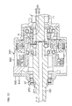
- Fig. 2 is a cross-sectional view showing a more specific configuration of the relevant parts in Fig. 1 .
- the housing 24 is configured by forming a metal such as an aluminum alloy into a tubular shape, for example, and includes first to third housings 51 to 53.
- first to eighth bearings 31 to 38 are accommodated.
- the first to fifth bearings 31 to 35 and the seventh and eighth bearings 37 to 38 are each rolling bearings such as an angular contact ball bearing, and the sixth bearing 36 is a rolling bearing such as a needle roller bearing.
- the first housing 51 is formed in a tubular shape and configures a differential mechanism housing for accommodating the transmission ratio variable mechanism 5 as a differential mechanism, and also configures a motor housing for accommodating the transmission ratio variable mechanism motor 23.
- One end of the first housing 51 is covered with an end wall member 54.
- One end of the first housing 51 and the end wall member 54 are fixed to each other by screwing members 55 such as bolts.
- An annular convex portion 57 at one end of the second housing 52 is fitted into an inner circumferential surface 56 at the other end of the first housing 51.
- the first and second housings 51 and 52 are fixed to each other by using screwing members (not shown) such as a bolt.
- the second housing 52 is formed in a tubular shape, and configures a sensor housing for accommodating the torque sensor 44 and a resolver housing for accommodating the motor resolver 43. Moreover, the second housing 52 accommodates therein a bus bar 99 (described later) of the transmission ratio variable mechanism motor 23 and a lock mechanism 58 for locking the rotor 231 of the transmission ratio variable mechanism motor 23. An outer circumferential surface 59 at the other end of the second housing 52 is fitted into an inner circumferential surface 60 at one end of the third housing 53.
- the third housing 53 is formed in a tubular shape, and configures a reduction gear mechanism housing for accommodating the reduction gear mechanism 26.
- An end wall section 61 is arranged at the other end of the third housing 53.
- the end wall section 61 is formed in an annular shape, and covers the other end of the third housing 53.
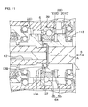
- Fig. 3 is an enlarged view of the transmission ratio variable mechanism 5 in Fig. 2 and a surrounding area thereof.
- the input member 20, the output member 22, and the inner race 391 of the transmission ratio variable mechanism 5 are each in an annular shape.
- the input member 20 includes an input member main body 201 and a tubular member 202 that is placed inward in a radial direction of the input member main body 201 and that is corotatably coupled to the input member main body 201.
- the second shaft 12, that is inserted through a through hole 22a of the output member 22, is corotatably coupled to the output member 22.
- the support mechanism 133 includes the tubular member 202 and the eighth bearing 38. That is, the tubular member 202 configures one portion of the input member 20 and configures one portion of the support mechanism 133.
- the tubular member 202 surrounds the respective facing end sections 11a and 12a of the first and second shafts 11 and 12. One end of the tubular member 202 opposes the first bearing 31 in the radial direction. The other end of the tubular member 202 opposes the facing end section 12a of the second shaft 12 in the radial direction.
- the other end of the tubular member 202 is formed with a bearing holding hole 109, and through the bearing holding hole 109, the facing end section 12a of the second shaft 12 is inserted thereinto.
- the eighth bearing 38 is interposed between the facing end section 12a of the second shaft 12 and the bearing holding hole 109, so as to permit relative rotation between the tubular member 202 and the second shaft 12.
- the tubular member 202 may be corotatably coupled to the facing end section 12a of the second shaft 12, and also the eighth bearing 38 may be interposed between the tubular member 202 and the facing end section 11a of the first shaft 11.
- the inner race 391 is placed outward in a radial direction of the tubular member 202.
- the outer race 392 is held corotatably by an inclined hole 63 formed in an inner circumferential section 233 of the rotor 231 of the transmission ratio variable mechanism motor 23, and corotates with the rotor 231 about the first axis A.
- the center line of the inclined hole 63 is the second axis B.
- the bearing ring unit 39 performs coriolis motion.
- the outer race 392 of the bearing ring unit 39 may couple differentially rotatably the input member 20 to the output member 22.
- the inner race 391 may be coupled corotatably to the rotor 231 of the transmission ratio variable mechanism motor 23.
- the bearing ring unit 39 becomes an inner race support type.
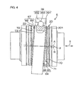
- Fig. 4 is a lateral side view of the transmission ratio variable mechanism 5 of which the one portion is expressed in cross section.
- First concavo-convex engaging section 64 includes a first convex portion 65 formed on a power transmission surface 70 as a one end surface of the input member main body 201 and a first concave portion 66 that is formed on a first end surface 71 as a one end surface of the inner race 391 and that is engaged with the first convex portion 65.
- the power transmission surface 70 and the first end surface 71 are opposed to each other in a shaft direction S of the steering shaft 3.
- the first concavo-convex engaging section 64 power-transmittably let the power transmission surface 70 engage with the first end surface 71.
- first concave portion 66 may be formed in an annular member formed separately of the inner race main body, and the annular member may be corotatably held by the inner race main body.
- the inner race main body and the annular member configure an inner race equivalent to the inner race 391.
- the placement of the first convex portion 65 may be replaced by that of the first concave portion 66.
- Second concavo-convex engaging section 67 includes a second convex portion 68 formed on a power transmission surface 72 as a one end surface of the output member 22 and a second concave portion 69 that is formed on a second end surface 73 as the other end surface of the inner race 391 and that is engaged with the second convex portion 68.
- the power transmission surface 72 and the second end surface 73 are opposed to each other in the shaft direction S of the steering shaft 3.
- the second concavo-convex engaging section 67 power-transmittably let the power transmission surface 72 engage with the second end surface 73.
- the second concave portion 69 may be formed in an annular member formed separately of the inner race main body, and the annular member may be corotatably held by the inner race main body.
- the inner race main body and the annular member configure an inner race equivalent to the inner race 391.
- the placement of the second convex portion 68 may be replaced by that of the second concave portion 69.
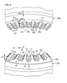
- Fig. 5 is a perspective view of the input member main body 201 and the inner race 391.
- each first convex portion 65 is formed at regular intervals over the entire circumference of a circumferential direction C1 of the input member 20.
- each first concave portion 66 is formed at regular intervals over the entire circumference of a circumferential direction C2 of the inner race 391.
- the number of first convex portions 65 to be formed is 38.
- the number of first concave portions 66 is different from that of the first convex portions 65. According to a difference between the number of first convex portions 65 and that of first concave portions 66, differential rotation can be generated between the input member main body 201 and the inner race 391.
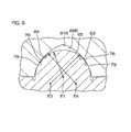
- Fig. 6 is a perspective view of the relevant parts of the input member main body 201 and the inner race 391.
- each first convex portion 65 is formed integrally, by using a single material, to the input member main body 201 of the input member 20, that is a corresponding member out of the input member 20, the inner race 391, and the output member 22, that is a member in which the first convex portion 65 is arranged.
- the first convex portion 65 and the input member main body 201 are collectively molded.
- methods of forming the first convex portion 65 and the input member main body 201 may include forging molding; casting molding; sinter molding: injection molding; metal injection molding; and cutting processing.
- metal injection molding metal powders are mixed with a binder so that injection molding can be performed as in the case of plastic. And after the injection, the binder is removed by heating, and the resultant material is sintered to a single unit of metal.
- the first convex portion 65 extends entirely over the power transmission surface 70 with respect to a radial direction R1 of the input member 20, for example, and is formed in a semicircular shape in cross section.
- the first convex portion 65 increases its cross sectional shape (semicircular shape) when seen from an inside of the radial direction R1 toward an outside thereof.
- the first convex portion 65 is also in a semicircular shape about a center line E1 flush with the power transmission surface 70 at any position in the radial direction R1.
- the first convex portion 65 progressively increases a width F1 with respect to the circumferential direction C1 of the input member 20 that is a corresponding member when seen from the inside of the radial direction R1 toward the outside thereof, and has a progressively increasing protruding amount G1 from the power transmission surface 70.
- the base end section 74 of the first convex portion 65 is arranged with relieving sections 75 for avoiding contact with the corresponding first concave portion 66.
- the relieving sections 75 are each formed at both ends of the first convex portion 65 with respect to the circumferential direction C1, and are configured by a trench that penetrates the input member main body 201 in the radial direction R1.
- Fig. 7 is a cross-sectional view showing engagement between the first convex portion 65 and the first concave portion 66.
- the first convex portion 65 is configured so that contact regions 76 of its external surface come in contact with contact regions 79 of the corresponding first concave portion 66.
- Each contact region 76 is arranged at a portion between the base end section 74 and the top section 77 of the first convex portion 65.
- the contact regions 76 are formed on both sides of the top section 77. The position and the width of each contact region 76 are determined based on a contact angle ⁇ of the first convex portion 65.
- the contact angle ⁇ of the contact region 76 of the first convex portion 65 is set within a range of between 15 and 75 degrees, for example.
- the contact region 76 is formed by using a low friction material for decreasing friction resistance.
- the low friction material contains a material having a friction coefficient lower than that of a material of the first convex portion 65.
- Examples of the low friction material include diamond-like carbon (DLC), a nitride obtained by performing a nitridation process on the first convex portion 65, a material obtained by performing a curing coat process, and a low- ⁇ coating material.
- DLC diamond-like carbon
- a nitride obtained by performing a nitridation process on the first convex portion 65 a material obtained by performing a curing coat process
- a low- ⁇ coating material low- ⁇ coating material.
- lubricant holding sections 78 are formed near the contact regions 76 of the input member main body 201.
- Each lubricant holding section 78 is for holding lubricant such as grease, and is disposed on the power transmission surface 70 of the input member main body 201, for example.
- the lubricant holding sections 78 are formed by knurl, cross hatch, dimple, etc., for example, formed on the power transmission surface 70, and have a large surface roughness of the power transmission surface 70.
- the lubricant holding sections 78 are formed by performing press molding, texturing, or shot peening processing on the power transmission surface 70.
- Each lubricant holding section 78 is formed in at least a portion of a flat section of the power transmission surface 70 where the first convex portions 65 are not formed. Moreover, the lubricant holding sections 78 may be formed in a portion where the contact regions 76 of each first convex portion 65 are not formed.
- Each first concave portion 66 is formed integrally, by using a single material, to the inner race 391 that is a member arranged with the first concave portion 66 that is a corresponding member selected from the input member 20, the inner race 391, and the output member 22.
- the first concave portion 66 is molded in a manner similar to the way that the above-described first convex portion 65 is molded.
- the first concave portion 66 is formed in a shape approximately matching that of the first convex portion 65. Specifically, the first concave portion 66 entirely extends over the first end surface 71 with respect to a radial direction R2 of the inner race 391, and is formed in a semicircular shape in cross section, for example.
- the first concave portion 66 increases its cross sectional shape (semicircular shape) from the inside of the radial direction R2 toward the outside thereof.
- the first concave portion 66 is formed in a semicircular shape about a center line E2 flush with the first end surface 71 at any position in the radial direction R2.
- the first concave portion 66 progressively increases a width F2 with respect to the circumferential direction C2 of the inner race 391 as a corresponding member from the inside of the radial direction R2 toward the outside thereof, and has a progressively increasing protruding amount G2 from the first end surface 71.
- the first concave portion 66 is configured so that the contact regions 79 on its surface come in contact with the contact regions 76 of the corresponding first convex portion 65.
- Each contact region 79 is arranged in a portion between an opening 80 and a bottom 81 of the first concave portion 66.
- the contact regions 79 are formed on both sides of the bottom 81. The position and the width of each contact region 79 are determined based on the preceding contact angle ⁇ .
- the contact regions 79 are formed by using a low friction material that is for decreasing a friction resistance.
- the low friction material include a low friction material similar to that of the contact regions 76 of the first convex portion 65.
- lubricant holding sections 82 are formed near the contact region 79 of the inner race 391. Each lubricant holding section 82 is for holding lubricant such as grease, and is disposed on the first end surface 71 of the inner race 391, for example.
- the lubricant holding section 82 has a configuration similar to that of the lubricant holding section 78 of the power transmission surface 70 of the input member main body 201.
- Each lubricant holding section 82 is formed in at least a portion of a flat section of the first end surface 71 where the first concave portions 66 are not formed.
- the lubricant holding sections 78 may be formed in a portion where the contact regions 79 of each first concave portion 66 are not formed.
- At least one of the lubricant holding section 78 near the first convex portion 65 and the lubricant holding section 82 near the first concave portion 66 may be removed. Further, at least one of the contact region 76 of the first convex portion 65 and the contact region 79 of the first concave portion 66 may be formed without using the low friction material.
- the first convex portion 65A may be formed so as to have the same cross sectional shape at any position in the radial direction R1 of the input member 20.
- the first concave portion 66A is formed so as to have the same cross sectional shape at any position in the radial direction R2 of the inner race 391.
- the cross section of the first concave portion 66B may be formed in a gothic arch shape.
- the respective center lines E3 and E4 of a first arcuate surface 83 and a second arcuate surface 84 on both sides of the bottom 81B of the first concave portion 66B are placed to be offset from each other.
- the power transmission surface 70 of the input member main body 201 and the first end surface 71 of the inner race 391 may be respectively formed with bevel gears thereby to configure the first concavo-convex engaging section
- the second end surface 73 of the inner race 391 and the power transmission surface 72 of the output member 22 may be respectively formed with bevel gears thereby to configure a second concavo-convex engaging section.
- the first convex portion and the second convex portion are configured by teeth of the bevel gears, respectively
- the first concave portion and the second concave portion are configured by grooves between the teeth of the bevel gears, respectively.
- the second convex portion 68 of the second concavo-convex engaging section 67 has a configuration similar to that of the first convex portion 65 of the first concavo-convex engaging section 64, and the second concave portion 69 has a configuration similar to that of the first concave portion 66.
- the power transmission surface 72 of the output member 22 has a configuration similar to that of the power transmission surface 70 of the input member main body 201
- the second end surface 73 of the inner race 391 has a configuration similar to that of the first end surface 71 of the inner race 391. Therefore, a detailed description of the second concavo-convex engaging section 67 will be omitted.
- the rotor 231 of the transmission ratio variable mechanism motor 23 includes a tubular shaped rotor core 85 extending in the shaft direction S and permanent magnets 86 fixed on the outer circumferential surface of the rotor core 85. Inward in the radial direction of the rotor core 85, the transmission ratio variable mechanism 5 and the torque sensor 44 are accommodated.
- the rotor core 85 both the first concavo-convex engaging section 64 and the second concavo-convex engaging section 67 of the transmission ratio variable mechanism 5 are surrounded over the entire circumference, and the torque sensor 44 is surrounded over the entire circumference.
- the transmission ratio variable mechanism 5 or the torque sensor 44 is accommodated within the rotor core 85, the length of the housing 24 with respect to the shaft direction S can be shortened. As a result, an energy absorbing stroke for absorbing the energy by a secondary vehicle collision can be secured long. Moreover, a placement space for a tilt telescopic mechanism (not shown) arranged adjacent to the housing 24 can also be secured.
- Examples of a material of the rotor core 85 include a steel, an aluminum alloy, a clad material, and a resin material.
- the clad material that is a composite material formed by bonding together a plurality of types of metals is used, the resonance can be reduced.
- the resin material is used for at least one portion of the rotor core 85 for weight saving, rotor inertia is decreased.
- a held hole 87 is formed at one end of the rotor core 85.
- an annular bearing holding section 88 is arranged at one end of the rotor core 85.
- the bearing holding section 88 is placed in the annular convex portion 89 formed on the inner circumferential side of one end of the first housing 51.
- the second bearing 32 is interposed between the held hole 87 and the bearing holding section 88, thereby the one end of the rotor core 85 can be rotatably supported by the first housing 51.
- a held hole 90 is formed. Inward in a radial direction of the held hole 90, an annular bearing holding section 91 is arranged.
- the bearing holding section 91 is placed in an annular extending section 92 formed on the inner circumferential side of one end of the second housing 52.
- the annular extending section 92 is formed in a tubular shape extending from a partition wall 93 arranged at the other end of the second housing 52 to one side S1 of the shaft direction S, and inserts through the rotor core 85.
- the fourth bearing 34 is interposed between the held hole 90 and the bearing holding section 91, thereby the intermediate portion of the rotor core 85 is rotatably supported by the annular extending section 92 of the second housing 52.
- the second and fourth bearings 32 and 34 as a pair of bearings placed in a manner to sandwich the bearing ring unit 39 in the shaft direction of the rotor 231, the rotor core 85 is both-end supported.
- the respective permanent magnets 86 of the rotor 231 have polarities alternately exchanging in a circumferential direction C3 of the steering shaft 3. N-poles and S-poles are alternately placed at regular intervals with respect to the circumferential direction C3.
- the permanent magnets 86 are fixed on the outer circumferential surface of the intermediate portion of the rotor core 85.
- the permanent magnets 86 and one portion of the transmission ratio variable mechanism 5 are overlapped in position with each other with respect to the shaft direction S.
- the stator 232 of the transmission ratio variable mechanism motor 23 is accommodated within an annular first groove-shaped section 94 formed at the other end of the first housing 51.
- the first groove-shaped section 94 is opened toward the other side S2 of the shaft direction S.
- the stator 232 includes a stator core 95 formed by stacking a plurality of layers of electromagnetic steel plates and an electromagnetic coil 96.
- the stator core 232 includes a toroidal-shaped yoke 97 and a plurality of teeth 98 that are placed at regular intervals in the circumferential direction of the yoke 97 and that are projecting inward in the radial direction of the yoke 97.
- the outer circumferential surface of the yoke 97 is fixed to the inner circumferential surface of the first groove-shaped section 94 of the second housing 52 by shrink fitting or any other similar technique.
- the electromagnetic coil 96 is wound around each of the teeth 98.
- the bus bar 99 On the other side S2 of the shaft direction S relative to the stator 232, the bus bar 99 is placed.
- the bus bar 99 is accommodated in the second housing 52 in an entirely annular shape, and is connected to each electromagnetic coil 96 of the transmission ratio variable mechanism motor 23.
- the bus bar 99 supplies electric power from the driving circuit to each electromagnetic coil 96.
- the bus bar 99 and one portion of the third and fourth bearings 33 and 34 are overlapped in position with respect to the shaft direction S.
- the lock mechanism 58 is for restricting the rotation of the rotor 231 of the transmission ratio variable mechanism motor 23, and is accommodated at one end of the second housing 52.
- the lock mechanism 58 includes a restricted section 100 corotatably coupled to the rotor core 85, and a restricting section 101 for restricting the rotation of the restricted section 100 by being engaged with the restricted section 100.
- the restricted section 100 is an annular member, and is formed, on the outer circumferential surface, with concave portions 102. At one or a plurality of locations with respect to the circumferential direction of the restricted section 100, each concave portion 102 is formed.
- the concave portion 102 may be arranged on the rotor core 85.
- the rotor core 85 configures the restricted section.
- One portion of the restricted section 100 is overlapped with one portion of the torque sensor 44 with respect to a position in the shaft direction S.
- the restricting section 101 is placed opposite to each restricted section 100 in the radial direction of the restricted section 100.
- the restricting section 101 is held by the second housing 52, and is movable to a side of the restricted section 100.
- the restricting section 101 moves to the side of the restricted section 100 so as to be engaged with the concave portion 102, and the rotation of the rotor core 85 is restricted.
- the motor resolver 43 is placed on the other side S2 of the shaft direction S relative to the lock mechanism 58.
- the motor resolover 43 is accommodated in a second groove-shaped section 103 formed at one end of the second housing 52, and is positioned outward in the radial direction of the rotor core 85.
- the second groove-shaped section 103 is an annular groove defined by the annular extending section 92 and an annular outer circumferential section 104 at one end of the second housing 52, and communicates with the first groove-shaped section 94.
- an accommodating space 139 for accommodating the transmission ratio variable mechanism motor 23, the lock mechanism 58, and the motor resolver 43 is defined.
- the motor resolver 43 and the torque sensor 44 are opposite to each other in the radial direction R3 of the steering shaft 3.
- One portion of the motor resolover 43 and one portion of the torque sensor 44 are overlapped in position with each other with respect to the shaft direction S.
- the motor resolover 43 includes a resolver rotor 105 and a resolver stator 106.
- the resolver rotor 105 is fixed corotatably to the outer circumferential surface 107 at the other end of the rotor core 85.
- the resolver stator 106 is fixed by a press fit on the inner circumferential surface 108 of the outer circumferential section 104 of the second housing 52.
- the first bearing 31 rotatably supports the input member 20.
- the first shaft 11 is rotatably supported by the first housing 51 via the tubular member 202 of the input member 20 and the first bearing 31.
- the first bearing 31 is surrounded by the second bearing 32, and the both components are overlapped in position with respect to the shaft direction S.
- the third bearing 33 is interposed between a bearing holding hole 110 formed in the inner circumferential section at the leading end of the extending section 92 of the second housing 52 and a bearing holding section 111 formed in the output member 22.
- the output member 22 is rotatably supported via the third bearing 33 by the annular extending section 92 of the second housing 52.
- the third bearing 33 is surrounded by the fourth bearing 34, and the both components are overlapped in position with respect to the shaft direction S.
- a preload is respectively imparted to the first concavo-convex engaging section 64 and the second concavo-convex engaging section 67, and thereby, smooth engagement between the first convex portion 65 and the first concave portion 66 and smooth engagement between the second convex portion 68 and the second concave portion 69 are respectively enabled.
- a screw member 113 is placed in the inner circumferential section 112 at one end of the first housing 51.
- the screw member 113 configures a biasing member for biasing the input member main body 201 in a bias direction H (the other side S2 of the shaft direction S) in which the input member main body 201 is brought close to the output member 22.
- the screw member 113 configures a rigid member for rigidly supporting the outer race 312 of the first bearing 31 with respect to the shaft direction S.
- the screw member 113 biases the input member main body 201 toward the output member 22, thereby to impart a preload to the first concavo-convex engaging section 64 and the second concavo-convex engaging section 67, respectively.
- a male screw section 113a formed on the outer circumferential surface of the screw member 113 is screwed into a female screw section 134a of the bearing holding hole 134 formed in the inner circumference of an annular convex portion 89 at one end of the first housing 51.
- the screw member 113 biases (presses against) one end surface of the outer race 312 of the first bearing 31 held in the bearing holding hole 134 of the first housing 51, in the bias direction H.
- the outer race 312 of the first bearing 31 is rotatable to the bearing holding hole 134 and is relatively movable to the shaft direction S.
- Adjacent to the screw member 113 a lock nut 135 is arranged. The lock nut 135 restricts the rotation of the screw member 113 in a state of being screwed into the female screw section 134a.
- the inner race 311 of the first bearing 31 is corotatably coupled to one end of the tubular member 202 by being press-fitted thereinto or other similar techniques, and is corotatable to the input member main body 201 and can be moved together therewith in the shaft direction S, via the tubular member 202.
- the inner race 311 comes into contact with one end section of the input member main body 201 so as to press against the input member main body 201 in the bias direction H.
- the first convex portion 65 of the first concavo-convex engaging section 64 opposes the first concave portion 66 in the bias direction H.
- the second concave portion 69 of the second concavo-convex engaging section 67 opposes the second convex portion 68 in the bias direction H.
- the inner race 331 of the third bearing 33 is fixed by a press fit.
- a step section of its center portion comes into contact with one end surface of the inner race 331 so as to press the inner race 331 in the bias direction H.
- the outer race 332 of the third bearing 33 is received by an annular step section 114 placed adjacent to the bearing holding hole 110 for movably holding the outer race 332 into the bias direction H, whereby the movement in the bias direction H is restricted.
- the movement of the output member 22 in the bias direction H is restricted by the third bearing 33.
- the biasing force of the screw member 113 is transmitted to the inner race 311 via the outer race 312 and the rolling element of the first bearing 31, and further transmitted to the input member main body 201.
- the biasing force transmitted to the input member main body 201 is transmitted to the first concavo-convex engaging section 64 and the second concavo-convex engaging section 67 in this order, and further transmitted to the inner race 331, the rolling element, and the outer race 332 of the third bearing 33.
- the biasing force transmitted to the outer race 332 of the third bearing 33 is received by the annular step section 114.
- the rolling elements 393, the outer race 392 of the bearing ring unit 39, and the rotor 231 of the transmission ratio variable mechanism motor 23 are moved all together in the bias direction H.
- the outer race 392 of the bearing ring unit 39 is fixed by a press fit to the inclined hole 63 of the rotor core 85.
- the rotor core 85 holds the outer race 392 in a manner to rotate together about the first axis A and to move together in the shaft direction S.
- the respective outer races 322 and 342 of the second bearing 32 and the fourth bearing 34 are loosely fitted to the corresponding annular held holes 87 and 90 of the rotor core 85, whereby the rotor core 85 is supported relatively movably in the shaft direction S.
- the inner race 321 of the second bearing 32 is fixed by a press fit to the bearing holding section 88 of the annular convex portion 89.
- the inner race 341 of the fourth bearing 34 is fixed by a press fit to the bearing holding section 91 of the annular extending section 92 of the second housing 52.
- the output member 22 may be biased in a bias direction (direction opposite to the bias direction H) in which the output member 22 is brought close to the input member main body 201.
- the screw member 113 is screwed into the bearing holding hole 110 for holding the third bearing 33.
- the biasing force of the screw member 113 is transmitted in the order of: the third bearing 33, the output member 22, the second concavo-convex engaging section 67, the first concavo-convex engaging section 64, the input member main body 201, the inner race 311, the rolling element, and the outer race 312 of the first bearing 31, and is received by the first housing 51.
- the movement of the inner race 391 in the bias direction H will not be inhibited by the support mechanism 133.
- the outer race 382 of the eighth bearing 38 of the support mechanism 133 is loosely fitted to the bearing holding hole 109 of the tubular member 202, and is relatively movable to the bearing holding hole 109 in the shaft direction S.
- the inner race 381 of the eighth bearing 38 is fixed by a press fit to the facing end section 12a of the second shaft 12.
- the outer race 382 of the eighth bearing 38 may be fixed by a press fit to the bearing holding hole 109, and the inner race 381 may be loosely fitted to the facing end section 12a.
- the torque sensor 44 is placed inward in the radial direction of the rotor core 85 of the transmission ratio variable mechanism motor 23, and includes: a multipole magnet 115 that is fixed to the intermediate portion of the second shaft 12; and magnetic yokes 116 and 117 as a pair of soft magnetic materials that are supported at one end of the third shaft 13 and that form a magnetic circuit by being placed within a magnetic field generated by the multipole magnet 115.
- the multipole magnet 115 is a cylinder-shaped permanent magnet, and is magnetized with a plurality of poles (equal in number between N-poles and S-poles) at regular intervals in the circumferential direction.
- the magnetic yokes 116 and 117 are opposed to the multipole magnet 115 with predetermined gaps in the radial direction of the multipole magnet 115, and surround the multipole magnet 115.
- Each of the magnetic yokes 116 and 117 is molded into a synthetic resin member 118.
- the synthetic resin member 118 is coupled corotatably to one end of the third shaft 13.
- the torque sensor 44 further includes a pair of magnetism collecting rings 119 and 120 for guiding a magnetic flux from the magnetic yokes 116 and 117.
- the pair of magnetism collecting rings 119 and 120 are each an annular member formed by using a soft magnetic material, and surround the magnetic yokes 116 and 117 so as to be magnetically coupled to each of the magnetic yokes 116 and 117.
- the pair of magnetism collecting rings 119 and 120 are opposed to each other to be spaced in the shaft direction S.
- the magnetism collecting rings 119 and 120 are molded by the synthetic resin member 121.
- the synthetic resin member 121 is held by the annular extending section 92 of the second housing 52.
- the magnetic flux occurs in the magnetic yokes 116 and 117 according to a relative rotation amount between the second and third shafts 12 and 13.
- the magnetic flux is guided by the magnetism collecting rings 119 and 120 and is detected by a hole IC (not shown) buried in the synthetic resin member 121. Thereby, it becomes possible to detect a magnetic flux density according to a torque applied to the second shaft 12 (steering member).
- the fifth bearing 35 On the other side S2 of the shaft direction S relative to the torque sensor 44, there is placed the fifth bearing 35.
- the fifth bearing 35 is interposed between a bearing holding section 122 formed in the outer circumference at one end of the third shaft 13 and a bearing holding hole 123 formed on the partition wall 93 of the second housing 52.
- the bearing holding hole 123 rotatably supports one end of the third shaft 13 via the fifth bearing 35.
- the third shaft 13 surrounds the second shaft 12 and the torsion bar 14. Specifically, the third shaft 13 is formed with a through hole 124 opened to one end of the third shaft 13. Through the through hole 124, the other end of the second shaft 12 is inserted. The second shaft 12 is formed with a through hole 125 extending in the shaft direction S, and through the through hole 125, the torsion bar 14 is inserted.
- One end of the torsion bar 14 is corotatably coupled to one end of the through hole 125 of the second shaft 12 by serration fitting or any other similar technique.
- the other end of the torsion bar 14 is corotatably coupled to the through hole 124 of the third shaft 13 by serration fitting or any other similar technique.
- a space inward in the radial direction of the annular extending section 92 of the second housing 52 is used as a torque sensor accommodating chamber 126, and a structure for inhibiting lubricant from intruding into the torque sensor accommodating chamber 126 is further provided.
- one end of the torque sensor accommodating chamber 126 is sealed by the third bearing 33 of sealed bearing placed at one end of the annular extending section 92 of the second housing 52, the output member 22 placed inward in the radial direction of the third bearing 33, and the second shaft 12 placed inward in the radial direction of the output member 22.
- the other end of the torque sensor accommodating chamber 126 is sealed, by the fifth bearing 35 of sealed bearing, the third shaft 13 placed inward in the radial direction of the fifth bearing 35, and the torsion bar 14 for clogging the through hole 124 of the third shaft 13.
- the reduction gear mechanism 26 is accommodated in the accommodating chamber 128 defined by the outer circumference section 127 and the end wall section 61 of the third housing 53, and the partition wall 93 of the second housing 52.
- One portion of the worm wheel 28 and the sixth bearing 36 are overlapped in position with respect to the shaft direction S.
- the seventh bearing 37 is interposed between the intermediate portion of the third shaft 13 and the end wall section 61 of the third housing 53.
- the end wall section 61 rotatably supports the third shaft 13 via the seventh bearing 37.
- the inner race 371 of the seventh bearing 37 is held by an annular step section 129 formed at the outer circumference section of the third shaft 13 and a nut member 130 screwed onto the outer circumference section of the third shaft 13.
- the outer race 372 of the seventh bearing 37 is held by an annular step section 131 formed in the third housing 53 and a retaining ring 132 held in the third housing 53.
- any of the cases of (i), (ii), and (iii) is described as follows: the number of first convex portions 65 of the first concavo-convex engaging section 64 is 38 and the number of the first concave portions 66 thereof is 40, and the number of the second convex portions 68 of the second concavo-convex engaging section 67 is 40 and the number of second concave portions 69 thereof is 40.
- the case of (i) that is, in a case that the rotation of the rotor 231 of the transmission ratio variable mechanism motor 23 is restricted by the lock mechanism 58, when the first shaft 11 is rotated by the operation of the steering member, the first convex portion 65 of the input member main body 201 is rotated about the first axis A.
- the bearing ring unit 39 does not perform coriolis motion, that is, rotation about the first axis A, but the inner race 391 only rotates about the second axis B. This rotation causes the rotation of inner race 391 arranged with the first concave portion 66, and further the rotation of the second shaft 12.
- the inner race 391 is caused to advance its phase by an amount equivalent to a difference in the number (two) of teeth while the outer race 392 of the bearing ring unit 39 makes one rotation. This results in the rotation of the inner race 391.
- the outer race 392 makes one rotation
- the inner race 391 is rotated by an amount equivalent to the difference in the number of teeth and the output member 22 makes 2/40 rotations.
- the rotation of the rotor 231 of the transmission ratio variable mechanism motor 23 is decelerated to 1/20, and the resultant rotations are output.
- a rotation amount of the output member 22 makes a value obtained by adding the rotation amount of the input member 20 (steering member) to the rotation amount of the case (ii).
- the steering angle ⁇ 1 may be amplified so as to exhibit a function of assisting the steering of the driver.
- the steering angle ⁇ 1 may be compared with the vehicle yaw rate ⁇ , for example, to determine a vehicle behavior.
- the rotation of the rotor 231 of the transmission ratio variable mechanism motor 23 may be increased or decreased in speed, whereby a vehicle stability control (attitude stability control) is performed.
- a vehicle stability control attitude stability control
- the first convex portions 65 of the first concavo-convex engaging section 64 are integrally formed in the input member main body 201
- the first and second concave portions 66 and 69 are integrally formed in the inner race 391
- the second convex portions 68 of the second concavo-convex engaging section 67 are integrally formed in the output member 22.
- the respective convex portions 65 and 68 and concave portions 66 and 69 of the first and second concavo-convex engaging sections 64 and 67, and the corresponding members 201, 391, and 22 are formed integrally by using a single material, and thus, the respective convex portions 65 and 68 (respective concave portions 66 and 69) and the corresponding members 201, 391, and 22 can be collectively formed, the number of manufacturing steps can be reduced.
- the relieving section 75 is arranged at the base end section 74 of the respective convex portions 65 and 68, and thus, when the respective convex portions 65 and 68 are engaged with the corresponding concave portions 66 and 69, the respective first and second convex portions 65 and 68 are prevented from being formed with an undercut thereof, whereby the respective convex portions 65 and 68 and concave portions 66 and 69 can be inhibited from wearing. Further, out of the respective convex portions 65 and 68 and concave portions 66 and 69, the more outward in the radial direction of the corresponding members 201, 391, and 22, the wider the widths F1 and F2 in the circumferential direction of the corresponding members 201, 391, and 22.
- corresponding lubricant holding sections 78 and 82 are arranged near the contact regions 76 and 79 of the respective convex portions 65 and 68 and concave portions 66 and 69. This enables supplying of the lubricant to the contact regions 76 and 79 from near the respective contact regions 76 and 79, thereby making the engagement between the respective convex portions 65 and 68 and the corresponding concave portions 66 and 69 more smooth. Further, the contact regions 76 and 79 of the respective convex portions 65 and 68 and concave portions 66 and 69 are formed by using a low friction material for decreasing a friction resistance. This further decreases the friction resistance caused when the respective concave portions 66 and 69 are engaged with the corresponding convex portions 65 and 68.
- the arrangement of the steering-assist-force imparting mechanism 19 enables imparting of the steering assist force to the turning mechanism 10, thereby reducing a force required by the driver for steering.
- the arrangement of the first and second concavo-convex engaging sections 64 and 67 on the respective sides, of the inner race 391 that is relatively small in diameter, out of the inner race 391 and the outer race 392, enables shortening of a support span in the radial direction when the inner race 391 is supported from the both sides in the axial direction by the input member 20 and the output member 22. This increases the supporting rigidity of the inner race 391.
- the concave portions 66 and 69 of the first and second concavo-convex engaging sections 64 and 67 are arranged on the respective sides of the inner race 391 that is relatively small in diameter, out of the inner race 391 and the outer race 392. Thereby, the circumferential speed of the concave portions 66 and 69 arranged in the inner race 391 can be decreased under driven, and thus, an engaging sound of the respective first and second concavo-convex engaging sections 64 and 67 can be decreased.
- the outer race 392 of the bearing ring unit 39 is surrounded by the rotor 231, and thus, it is possible to inhibit a meshing sound of the respective first and second concavo-convex engaging sections 64 and 67 from being transmitted to the outside of the rotor 231, thereby further decreasing the noise.
- the second axis B as a center line of the outer race 392 can be kept inclined to the first axis A.
- the rotor core 85 can be both-end supported by the second and the fourth bearings 32 and 34, and thus, the supporting rigidity of the rotor 231 can be increased. Also, the placement of the inner race 391 between the second and fourth bearings 32 and 34 enables firmly supporting the rotor core 85 for receiving the force from the inner race 391, thereby inhibiting the runout of the rotor 231. As a result, it is possible to contribute to a decrease in noise.
- the mutual facing end sections 11a and 12a of the first and second shafts 11 and 12 are mutually supported by the eighth bearing 38, and thus, the mutual coaxiality of the first and second shafts 11 and 12 can be improved.
- the mutual runout or center deviation of the input member 20 and the output member 22 with respect to others can be inhibited, and it is possible to prevent a state of engagement between the convex portions 65 and 68 and the corresponding concave portions 66 and 69 in the respective concavo-convex engaging sections 64 and 67 from being inadvertently changed, thereby stopping an increase of an engaging sound.
- the support mechanism 133 can be realized. Further, the arrangement of the eighth bearing 38 between the first shaft 11 and the second shaft 12 enables a smooth relative rotation of the first and second shafts 11 and 12.
- the operation of the steering member 2 by the driver can be corrected by the transmission ratio variable mechanism 5, and thus, a so-called active steering in which a counter steering operation is automatically performed by the transmission ratio variable mechanism 5 is enabled, for example.
- preloads are imparted between the respective convex portions 65 and 68 and corresponding concave portions 66 and 69.
- the support span in the radial direction can be shortened where the inner race 391 is supported from the both sides in the shaft direction by the input member 20 and the output member 22, thereby decreasing a deformation of the inner race 391 that results from the biasing force from the screw member 113.
- a sufficient biasing force can be acted on the respective concave portions 66 and 69 formed in the inner race 391, and thus, rattling in the respective first and second concavo-convex engaging sections 64 and 67 can be reliably prevented from being generated.
- the screw member 113 biases the input member 20 toward the output member 22, and thereby, the biasing force of the screw member 113 can be transmitted in the order of: the input member 20; the first concavo-convex engaging section 64 arranged on the side of the first end surface 71 of the inner race 391; the second concavo-convex engaging section 67 arranged on the side of the second end surface 73 of the inner race 391; and the output member 22. Further, the preload can be imparted by the screw member 113 to the first bearing 31, and thus, an abnormal sound resulting from the first bearing 31 can be prevented from being generated.
- the biasing force by the screw member 113 can be adjusted.
- the biasing force of the screw member 113 can be transmitted to the inner race 311 of the first bearing 31 via the outer race 312 of the first bearing 31, and thereby, the preload can be reliably imparted to the first bearing 31.
- the force generated when the output member 22 unforcedly makes movement in the bias direction H can be received by the third bearing 33, and thus, the preload can be imparted to the third bearing 33.
- the second and fourth bearings 32 and 34 support the rotor 231 movably in the shaft direction S. Thereby, along with the movement of the inner race 391 by the biasing force of the screw member 113 in the shaft direction of the rotor 231, the outer race 392 and the rotor 231 can be moved together in the shaft direction of the rotor 231, and as a result, an unnecessary force can be prevented from being acted between the inner race 391 and the outer race 392.
- output of the transmission ratio variable mechanism 5 is transmitted via the steering-assist-force imparting mechanism 19 to the turning mechanism 10.
- the output can be transmitted to the turning mechanism 10 without use of the transmission ratio variable mechanism 5.
- the power input to the transmission ratio variable mechanism 5 can be decreased, and thus, the transmission ratio variable mechanism 5 can be made compact.
- the input member 20, the inner race 391, and the output member 22 are aligned in a direction (shaft direction S) in which the first axis A extends, and thereby, the transmission ratio variable mechanism 5 can be made compact with respect to the radial direction of the input member 20 and the output member 22 (radial direction R3). As a result, the transmission ratio variable mechanism 5 can be made more compact.
- the rotor core 85 of the rotor 231 of the transmission ratio variable mechanism motor 23 is formed in a tubular shape surrounding the first and second concavo-convex engaging sections 64 and 67.
- the rotor 231 and the first and second concavo-convex engaging sections 64 and 67 can be placed at a position overlapping with respect to the shaft direction S, and thereby, further compactness of the motor vehicle steering system 1 can be achieved.
- the rotor 231 can be used as a soundproof wall, and thus, leaking of the meshing sound of the first and second concavo-convex engaging sections 64 and 67 to the outside can be inhibited.
- the torque sensor 44 is surrounded by the rotor core 85 of the rotor 231 of the transmission ratio variable mechanism motor 23, and thereby, the rotor 231 and the torque sensor 44 can be placed at a position overlapping with respect to the shaft direction S.
- the transmission ratio variable mechanism 5 and the steering-assist-force imparting mechanism 19 are arranged, as steering columns, in the housing 24.
- the embodiment offers superior noise reduction, and thus, even when the transmission ratio variable mechanism 5 and the steering-assist-force imparting mechanism 19 are arranged in the vehicle compartment where the housing 24 is placed, there is little influence from the driving sound.
- the steering-assist-force imparting mechanism 19 in Fig. 1 may be eliminated.
- points different from those in the preceding embodiment are mainly described.
- Like reference numerals are assigned in a similar configuration to omit description.
- the driving circuit 41, the steering assisting motor 25, the reduction gear mechanism 26, the third shaft 13, the torsion bar 14, and the torque sensor 44 shown in Fig. 1 are eliminated. Further, the other end of the second shaft 12 is coupled to the universal joint 9.
- an end wall section 61C of a third housing 53C is fixed to a second housing 52C in a state of being caused to run along the other end of the second housing 52C.
- the third housing 53C no accommodating chamber for accommodating a reduction gear mechanism is arranged.
- the second shaft 12C that extends to the other end of the third housing 53C and protrudes to the outside of the housing 24C, is connected to a turning mechanism (not shown).
- An intermediate portion of the second shaft 12C is corotatably coupled with the inner race 371 of the seventh bearing 37.
- an input member 20D instead of the input member 20, it may be possible to use an input member 20D formed so that an input member main body 201D and a tubular member 202D are integrally formed by using a single member.
- the first convex portions 65 of the first concavo-convex engaging section 64 are integrally formed with the input member 20D as a corresponding member by using a single member.
- a tubular member 202D and an output member 22D of the input member 20D include facing surfaces 136 and 137 that are opposed to each other.
- the facing surfaces 136 and 137 are opposed to each other while arranging a gap 138 in the shaft direction S as a direction parallel to the first axis A.
- the input member 20D and the first convex portions 65 are formed integrally by a single member, and thereby, the first convex portions 65 and the input member 20D can be collectively formed. As a result, the number of manufacturing steps can be reduced.
- a bearing ring unit 39 provided with an outer race for differentially rotatably coupling the input member 20 and the output member 22 and an inner race for rotatably supporting the outer race via rolling elements.
Claims (15)
- Système de direction de véhicule automobile, comprenant : un mécanisme de transmission à rapport variable (5) permettant de changer un rapport de transmission (θ2/θ1) d'un angle de braquage (θ2) des roues directrices (4L, 4R) par rapport à un angle de direction (θ2) d'un élément de direction (2) ; et un mécanisme communiquant une force d'assistance de direction (19) utilisé pour communiquer une force d'assistance de direction, la sortie du mécanisme de transmission à rapport variable (5) étant transmise au mécanisme de braquage (10) par l'intermédiaire du mécanisme communiquant la force d'assistance de direction (19),
le mécanisme de transmission à rapport variable (5) comprenant :un élément d'entrée (20) et un élément de sortie (22) pouvant tourner autour d'un premier axe (A),une première bague de roulement (391), comportant une première et une seconde surface d'extrémité (71, 73), pour coupler en leur permettant une rotation différentielle l'élément d'entrée (20) et l'élément de sortie (22),une seconde bague de roulement (392) pour supporter de façon rotative la première bague de roulement (391) par l'intermédiaire d'un élément de roulement (393), etun actionneur (23) permettant d'entraîner en rotation la seconde bague de roulement (392),dans lequel un second axe (B) est dans l'axe de la première bague de roulement (391) et la seconde bague de roulement (392) est inclinée par rapport au premier axe (A),caractérisé en ce que l'élément d'entrée (20) et l'élément de sortie (22) ont respectivement des surfaces de transmission d'entrainement (70, 72) qui sont chacune opposées à la première et à la seconde surface d'extrémité de la première bague de roulement (391),dans lequel une première unité concave-convexe de mise en prise (64) est disposée pour mettre en prise, de façon à transmettre l'entraînement, la première surface d'extrémité de la première bague de roulement (391) et la surface de transmission d'entraînement de l'élément d'entrée (20) correspondant à la première surface d'extrémité, la première unité concave-convexe de mise en prise (64) comportant une première partie convexe (65) qui est agencée sur une de la première surface d'extrémité et de la surface de transmission d'entraînement correspondant à la première surface d'extrémité, et une première partie concave (66) qui est agencée sur une surface alterne et qui est mise en prise avec la première partie convexe, etdans lequel une seconde unité concave-convexe de mise en prise (67) est disposée pour mettre en prise, de façon à transmettre l'entraînement, la seconde surface d'extrémité de la première bague de roulement (391) et la surface de transmission d'entraînement de l'élément de sortie (22) correspondant à la seconde surface d'extrémité, la seconde unité concave-convexe de mise en prise (67) comportant une seconde partie convexe (68) agencée sur une de la seconde surface d'extrémité et de la surface de transmission d'entraînement correspondant à la seconde surface d'extrémité, et une seconde partie concave (69) qui est agencée sur une surface alterne et mise en prise avec la seconde partie convexe (68). - Système de direction de véhicule automobile selon la revendication 1, dans lequel
l'actionneur (23) comprend un moteur électrique, et
le moteur électrique comprend un rotor servant à maintenir de façon co-rotative la seconde bague de roulement (392) et pouvant tourner autour du premier axe (A). - Système de direction de véhicule automobile selon la revendication 2, dans lequel
le rotor a une forme tubulaire entourant la première section concave-convexe de mise en prise et la seconde section concave-convexe de mise en prise. - Système de direction de véhicule automobile selon la revendication 2, dans lequel
le rotor est formé avec un trou incliné, et a un axe s'étendant le long du second axe (B), pour porter la seconde bague de roulement (392). - Système de direction de véhicule automobile selon la revendication 2, dans lequel
le rotor est porté à ses deux extrémités par un deuxième palier et un quatrième palier retenus dans un logement, et la première bague de roulement (391) est placée entre le deuxième palier et le quatrième palier par rapport à la direction de l'arbre de rotor. - Système de direction de véhicule automobile selon la revendication 5, dans lequel
le deuxième palier et le quatrième palier supportent de façon mobile le rotor par rapport à la direction de l'arbre de rotor. - Système de direction de véhicule automobile selon la revendication 1, comprenant en outre :un premier arbre inséré à travers un trou traversant pratiqué dans l'élément d'entrée (20) et connecté pour la co-rotation avec l'élément d'entrée (20) ;un second arbre inséré à travers un trou traversant pratiqué dans l'élément de sortie (22) et connecté pour la co-rotation avec l'élément de sortie (22) ; etun mécanisme de support pour supporter coaxialement, en rotation relative, les sections d'extrémités du premier arbre et du second arbre qui se font mutuellement face.
- Système de direction de véhicule automobile selon la revendication 1, comprenant en outre un élément de sollicitation qui sollicite les éléments d'entrée et de sortie dans une direction de rappel dans laquelle l'un de l'élément d'entrée (20) et de l'élément de sortie (22) est rapproché de l'autre élément d'entrée (20) ou élément de sortie (22),
une précharge étant exercée sur la première section concave-convexe de mise en prise et sur la seconde section concave-convexe de mise en prise par l'élément de sollicitation. - Système de direction de véhicule automobile selon la revendication 8, comprenant en outre un premier palier, retenu dans un logement, pour supporter de façon rotative l'élément d'entrée (20), dans lequel
l'élément de sollicitation sollicite l'élément d'entrée (20) par l'intermédiaire du premier palier. - Système de direction de véhicule automobile selon la revendication 8, comprenant en outre un troisième palier, retenu dans le logement, pour supporter de façon rotative l'élément de sortie (22), dans lequel
le mouvement de l'élément de sortie (22), dans la direction de rappel est limité par le troisième palier. - Système de direction de véhicule automobile selon la revendication 1, dans lequel
les parties convexes et les parties concaves de la première et de la seconde section concave-convexe de mise en prise sont respectivement formées intégralement avec un élément correspondant, de l'élément d'entrée (20), de la première bague de roulement (391), et de l'élément de sortie (22). - Système de direction de véhicule automobile selon la revendication 11, dans lequel
à une section d'extrémité base de la première partie convexe (65) et/ou à une section d'extrémité base de la seconde partie convexe (68), une section de détente est agencée pour éviter le contact avec une partie concave correspondante. - Système de direction de véhicule automobile selon la revendication 1, dans lequel
l'élément d'entrée (20), l'élément de sortie (22), et la première bague de roulement (391) ont respectivement une forme annulaire, et
la première partie convexe (65), la seconde partie convexe (68), la première partie concave (66), et la seconde partie concave (69) s'étendent respectivement dans une direction radiale et ont une largeur qui s'accroit progressivement par rapport à une direction circonférentielle, d'une partie interne d'une direction radiale à une partie externe de celle-ci. - Système de direction de véhicule automobile selon la revendication 2, dans lequel
le mécanisme communiquant la force d'assistance de direction (19) comprend un arbre d'entrée couplé à l'élément de sortie (22), un arbre de sortie couplé au mécanisme de braquage (10), et un capteur de couple (44) pour détecter un couple transmis entre l'arbre d'entrée et l'arbre de sortie, et dans lequel
le capteur de couple (44) est entouré par le rotor. - Système de direction de véhicule automobile selon la revendication 14, dans lequel le mécanisme de transmission à rapport variable (5) et le mécanisme communiquant la force d'assistance de direction (19) sont agencés dans une colonne de direction.
Applications Claiming Priority (2)
| Application Number | Priority Date | Filing Date | Title |
|---|---|---|---|
| JP2007274480A JP5234314B2 (ja) | 2007-10-22 | 2007-10-22 | 車両用操舵装置 |
| PCT/JP2008/068891 WO2009054328A1 (fr) | 2007-10-22 | 2008-10-17 | Dispositif de direction pour véhicule |
Publications (3)
| Publication Number | Publication Date |
|---|---|
| EP2202130A1 EP2202130A1 (fr) | 2010-06-30 |
| EP2202130A4 EP2202130A4 (fr) | 2011-09-28 |
| EP2202130B1 true EP2202130B1 (fr) | 2012-12-05 |
Family
ID=40579434
Family Applications (1)
| Application Number | Title | Priority Date | Filing Date |
|---|---|---|---|
| EP08841871A Not-in-force EP2202130B1 (fr) | 2007-10-22 | 2008-10-17 | Dispositif de direction pour vehicule |
Country Status (5)
| Country | Link |
|---|---|
| US (1) | US8181734B2 (fr) |
| EP (1) | EP2202130B1 (fr) |
| JP (1) | JP5234314B2 (fr) |
| CN (1) | CN101835673B (fr) |
| WO (1) | WO2009054328A1 (fr) |
Families Citing this family (17)
| Publication number | Priority date | Publication date | Assignee | Title |
|---|---|---|---|---|
| WO2009054325A1 (fr) | 2007-10-22 | 2009-04-30 | Jtekt Corporation | Mécanisme de transmission à rapport variable et dispositif de direction pour véhicule équipé de celui-ci |
| JP5136842B2 (ja) * | 2007-12-25 | 2013-02-06 | 株式会社ジェイテクト | 車両用操舵装置 |
| US8100104B2 (en) * | 2008-06-05 | 2012-01-24 | Ford Global Technologies | Torsion lock encoder device for internal combustion engine |
| JP5229543B2 (ja) * | 2008-06-30 | 2013-07-03 | 株式会社ジェイテクト | 車両用操舵装置 |
| JP5282938B2 (ja) * | 2008-07-07 | 2013-09-04 | 株式会社ジェイテクト | 伝達比可変機構およびこれを備える車両用操舵装置 |
| JP5224109B2 (ja) * | 2008-08-27 | 2013-07-03 | 株式会社ジェイテクト | 車両用操舵装置 |
| JP5227853B2 (ja) * | 2009-03-09 | 2013-07-03 | 株式会社ジェイテクト | 揺動型歯車装置、伝達比可変機構、および車両用操舵装置 |
| JP2014035016A (ja) * | 2012-08-08 | 2014-02-24 | Jtekt Corp | 伝達比可変装置 |
| CN103407485A (zh) * | 2013-07-26 | 2013-11-27 | 豫北转向系统股份有限公司 | 一种汽车电动助力转向器的蜗轮支撑结构 |
| JP6531997B2 (ja) | 2015-09-30 | 2019-06-19 | 本田技研工業株式会社 | シャフトの軸受構造 |
| CN106853841A (zh) * | 2015-12-09 | 2017-06-16 | 上海航天汽车机电股份有限公司 | 电动助力转向系统安装非接触式传感器的转向轴 |
| CN108602530A (zh) * | 2016-02-17 | 2018-09-28 | 日本精工株式会社 | 车辆用转向控制装置 |
| JP6756214B2 (ja) | 2016-09-26 | 2020-09-16 | セイコーエプソン株式会社 | ロボット、歯車装置および歯車装置の製造方法 |
| JP6394670B2 (ja) * | 2016-10-06 | 2018-09-26 | トヨタ自動車株式会社 | 車両用動力伝達装置 |
| CN110998115B (zh) * | 2017-08-02 | 2022-07-15 | Thk株式会社 | 减速或者增速装置 |
| FR3083770B1 (fr) * | 2018-07-10 | 2020-06-19 | Jtekt Europe | Procede de controle d’un systeme de direction avec deux motorisations redondantes |
| MD4781C1 (ro) * | 2019-12-31 | 2022-07-31 | Виорел БОСТАН | Transmisii planetare precesionale |
Family Cites Families (25)
| Publication number | Priority date | Publication date | Assignee | Title |
|---|---|---|---|---|
| US3935750A (en) * | 1973-10-23 | 1976-02-03 | Maroth Arthur M | Counterbalanced mechanical speed-change mechanism |
| US3994186A (en) * | 1975-05-09 | 1976-11-30 | Marquette Metal Products Company | Gear train speed changing transmission |
| JPS6011749A (ja) | 1983-06-30 | 1985-01-22 | Sanwa Tekki Corp | 断面円弧歯のフエ−スギア装置 |
| IT1198111B (it) * | 1986-11-18 | 1988-12-21 | Gian Piero Barozzi | Riduttore compatto privo di giochi a forte rapporto di riduzione,particolarmente per manipolatori automatici e simili |
| JP2719921B2 (ja) | 1988-03-10 | 1998-02-25 | 株式会社マキシンコー | フェースギャの歯形、該歯形の創成加工方法及び該歯形を利用した差動減速装置 |
| JP2684430B2 (ja) * | 1989-11-01 | 1997-12-03 | 一郎 上村 | 伝動差動式推力発生装置 |
| JPH0756324A (ja) | 1993-08-10 | 1995-03-03 | Kuraray Co Ltd | 拡散型フォトマスク及びそれを使用する光学部品の製造法 |
| JPH09132153A (ja) * | 1995-11-06 | 1997-05-20 | Toyoda Mach Works Ltd | 電気式動力舵取装置 |
| JPH10246293A (ja) * | 1997-03-04 | 1998-09-14 | Namu:Kk | 変速歯車装置 |
| JP3539468B2 (ja) * | 1997-06-13 | 2004-07-07 | トヨタ自動車株式会社 | 車両用操舵装置 |
| JP3248568B2 (ja) | 1997-09-12 | 2002-01-21 | トヨタ自動車株式会社 | ステアリング装置 |
| DE19839720C1 (de) * | 1998-09-01 | 1999-11-25 | Gkn Viscodrive Gmbh | Drehmoment-abhängig reagierendes Sperrdifferential mit wenigen Teilen |
| US7824271B2 (en) * | 2002-06-01 | 2010-11-02 | Daimler Ag | Device for adjusting the relative angular position of two rotating elements |
| JP2004190846A (ja) * | 2002-12-06 | 2004-07-08 | Kawaden:Kk | バルブ用アクチュエータ |
| JP4465240B2 (ja) * | 2004-08-02 | 2010-05-19 | 荻野工業株式会社 | 変速歯車装置、およびそれを用いた自動車の操舵装置 |
| JP4524595B2 (ja) * | 2004-09-16 | 2010-08-18 | 株式会社ジェイテクト | 舵角比可変操舵装置 |
| JP4520804B2 (ja) * | 2004-09-21 | 2010-08-11 | 荻野工業株式会社 | 電動パワーステアリング装置 |
| DE102004052562B3 (de) | 2004-10-29 | 2006-02-09 | Thyssen Krupp Automotive Ag | Kraftfahrzeuglenkung mit Überlagerungsgetriebe |
| JP4799127B2 (ja) | 2005-10-28 | 2011-10-26 | 荻野工業株式会社 | 位置決め装置 |
| JP5011706B2 (ja) | 2005-11-01 | 2012-08-29 | 株式会社ジェイテクト | 車両用操舵装置 |
| JP2007170624A (ja) * | 2005-12-26 | 2007-07-05 | Toyota Motor Corp | 伝達比可変装置および車両操舵装置 |
| JP2008030747A (ja) | 2007-09-11 | 2008-02-14 | Ogino Kogyo Kk | ステアリング装置 |
| WO2009054325A1 (fr) | 2007-10-22 | 2009-04-30 | Jtekt Corporation | Mécanisme de transmission à rapport variable et dispositif de direction pour véhicule équipé de celui-ci |
| JP5136842B2 (ja) * | 2007-12-25 | 2013-02-06 | 株式会社ジェイテクト | 車両用操舵装置 |
| JP5227853B2 (ja) * | 2009-03-09 | 2013-07-03 | 株式会社ジェイテクト | 揺動型歯車装置、伝達比可変機構、および車両用操舵装置 |
-
2007
- 2007-10-22 JP JP2007274480A patent/JP5234314B2/ja not_active Expired - Fee Related
-
2008
- 2008-10-17 CN CN2008801123622A patent/CN101835673B/zh not_active Expired - Fee Related
- 2008-10-17 WO PCT/JP2008/068891 patent/WO2009054328A1/fr active Application Filing
- 2008-10-17 US US12/738,177 patent/US8181734B2/en not_active Expired - Fee Related
- 2008-10-17 EP EP08841871A patent/EP2202130B1/fr not_active Not-in-force
Also Published As
| Publication number | Publication date |
|---|---|
| WO2009054328A1 (fr) | 2009-04-30 |
| EP2202130A1 (fr) | 2010-06-30 |
| EP2202130A4 (fr) | 2011-09-28 |
| US20100224436A1 (en) | 2010-09-09 |
| US8181734B2 (en) | 2012-05-22 |
| CN101835673A (zh) | 2010-09-15 |
| CN101835673B (zh) | 2012-06-13 |
| JP2009101803A (ja) | 2009-05-14 |
| JP5234314B2 (ja) | 2013-07-10 |
Similar Documents
| Publication | Publication Date | Title |
|---|---|---|
| EP2202130B1 (fr) | Dispositif de direction pour vehicule | |
| EP2202131B1 (fr) | Mecanisme de transmission a rapport variable et dispositif de direction pour vehicule equipe de celui-ci | |
| EP2298624B1 (fr) | Mécanisme de changement de rapport de transmission et dispositif de direction de véhicule | |
| EP2233383B1 (fr) | Dispositif de direction pour véhicule | |
| EP2298623B1 (fr) | Mécanisme de changement de rapport de transmission et dispositif de direction de véhicule | |
| US20090101431A1 (en) | Steering apparatus for motor vehicle | |
| JP2009171736A (ja) | 電動モータ | |
| EP2308742B1 (fr) | Mécanisme à rapport de transmission variable et dispositif de direction à rapport variable | |
| WO2016129436A1 (fr) | Dispositif de direction de roue arrière | |
| JP5234313B2 (ja) | 車両用操舵装置 | |
| EP2733044A2 (fr) | Dispositif de transmission à rapport variable | |
| JP5110361B2 (ja) | 伝達比可変機構およびこれを備える車両用操舵装置 | |
| JP5110362B2 (ja) | 伝達比可変機構およびこれを備える車両用操舵装置 | |
| JP5158419B2 (ja) | 車両用操舵装置 | |
| JP2019214311A (ja) | 後輪操舵装置および車両 | |
| EP2733045A2 (fr) | Dispositif de transmission à rapport variable | |
| JP2010006341A (ja) | 車両用操舵装置 | |
| JP2010274771A (ja) | 車両用操舵装置 |
Legal Events
| Date | Code | Title | Description |
|---|---|---|---|
| PUAI | Public reference made under article 153(3) epc to a published international application that has entered the european phase |
Free format text: ORIGINAL CODE: 0009012 |
|
| 17P | Request for examination filed |
Effective date: 20100331 |
|
| AK | Designated contracting states |
Kind code of ref document: A1 Designated state(s): AT BE BG CH CY CZ DE DK EE ES FI FR GB GR HR HU IE IS IT LI LT LU LV MC MT NL NO PL PT RO SE SI SK TR |
|
| AX | Request for extension of the european patent |
Extension state: AL BA MK RS |
|
| DAX | Request for extension of the european patent (deleted) | ||
| A4 | Supplementary search report drawn up and despatched |
Effective date: 20110831 |
|
| RIC1 | Information provided on ipc code assigned before grant |
Ipc: F16H 1/32 20060101ALI20110825BHEP Ipc: B62D 5/04 20060101AFI20110825BHEP Ipc: B62D 1/16 20060101ALI20110825BHEP |
|
| REG | Reference to a national code |
Ref country code: DE Ref legal event code: R079 Ref document number: 602008020676 Country of ref document: DE Free format text: PREVIOUS MAIN CLASS: B62D0005040000 Ipc: B62D0005000000 |
|
| RIC1 | Information provided on ipc code assigned before grant |
Ipc: B62D 5/04 20060101ALI20120418BHEP Ipc: B62D 5/00 20060101AFI20120418BHEP |
|
| GRAP | Despatch of communication of intention to grant a patent |
Free format text: ORIGINAL CODE: EPIDOSNIGR1 |
|
| RIN1 | Information on inventor provided before grant (corrected) |
Inventor name: SAITOU, YASUHIRO Inventor name: NAKAOKA, MASAKI Inventor name: TSUJI, YASUAKI Inventor name: OTSUKI, HIDETAKA Inventor name: TSUCHIMOCHI, SUNAO Inventor name: YAMAKAWA, TOMONARI Inventor name: SHIINA, AKIHIKO |
|
| GRAS | Grant fee paid |
Free format text: ORIGINAL CODE: EPIDOSNIGR3 |
|
| GRAA | (expected) grant |
Free format text: ORIGINAL CODE: 0009210 |
|
| AK | Designated contracting states |
Kind code of ref document: B1 Designated state(s): AT BE BG CH CY CZ DE DK EE ES FI FR GB GR HR HU IE IS IT LI LT LU LV MC MT NL NO PL PT RO SE SI SK TR |
|
| REG | Reference to a national code |
Ref country code: GB Ref legal event code: FG4D |
|
| REG | Reference to a national code |
Ref country code: CH Ref legal event code: EP |
|
| REG | Reference to a national code |
Ref country code: AT Ref legal event code: REF Ref document number: 587099 Country of ref document: AT Kind code of ref document: T Effective date: 20121215 |
|
| REG | Reference to a national code |
Ref country code: IE Ref legal event code: FG4D |
|
| REG | Reference to a national code |
Ref country code: DE Ref legal event code: R096 Ref document number: 602008020676 Country of ref document: DE Effective date: 20130131 |
|
| REG | Reference to a national code |
Ref country code: AT Ref legal event code: MK05 Ref document number: 587099 Country of ref document: AT Kind code of ref document: T Effective date: 20121205 |
|
| PG25 | Lapsed in a contracting state [announced via postgrant information from national office to epo] |
Ref country code: FI Free format text: LAPSE BECAUSE OF FAILURE TO SUBMIT A TRANSLATION OF THE DESCRIPTION OR TO PAY THE FEE WITHIN THE PRESCRIBED TIME-LIMIT Effective date: 20121205 Ref country code: SE Free format text: LAPSE BECAUSE OF FAILURE TO SUBMIT A TRANSLATION OF THE DESCRIPTION OR TO PAY THE FEE WITHIN THE PRESCRIBED TIME-LIMIT Effective date: 20121205 Ref country code: ES Free format text: LAPSE BECAUSE OF FAILURE TO SUBMIT A TRANSLATION OF THE DESCRIPTION OR TO PAY THE FEE WITHIN THE PRESCRIBED TIME-LIMIT Effective date: 20130316 Ref country code: NO Free format text: LAPSE BECAUSE OF FAILURE TO SUBMIT A TRANSLATION OF THE DESCRIPTION OR TO PAY THE FEE WITHIN THE PRESCRIBED TIME-LIMIT Effective date: 20130305 Ref country code: LT Free format text: LAPSE BECAUSE OF FAILURE TO SUBMIT A TRANSLATION OF THE DESCRIPTION OR TO PAY THE FEE WITHIN THE PRESCRIBED TIME-LIMIT Effective date: 20121205 |
|
| REG | Reference to a national code |
Ref country code: NL Ref legal event code: VDEP Effective date: 20121205 |
|
| REG | Reference to a national code |
Ref country code: LT Ref legal event code: MG4D |
|
| PG25 | Lapsed in a contracting state [announced via postgrant information from national office to epo] |
Ref country code: GR Free format text: LAPSE BECAUSE OF FAILURE TO SUBMIT A TRANSLATION OF THE DESCRIPTION OR TO PAY THE FEE WITHIN THE PRESCRIBED TIME-LIMIT Effective date: 20130306 Ref country code: SI Free format text: LAPSE BECAUSE OF FAILURE TO SUBMIT A TRANSLATION OF THE DESCRIPTION OR TO PAY THE FEE WITHIN THE PRESCRIBED TIME-LIMIT Effective date: 20121205 Ref country code: PL Free format text: LAPSE BECAUSE OF FAILURE TO SUBMIT A TRANSLATION OF THE DESCRIPTION OR TO PAY THE FEE WITHIN THE PRESCRIBED TIME-LIMIT Effective date: 20121205 Ref country code: LV Free format text: LAPSE BECAUSE OF FAILURE TO SUBMIT A TRANSLATION OF THE DESCRIPTION OR TO PAY THE FEE WITHIN THE PRESCRIBED TIME-LIMIT Effective date: 20121205 |
|
| PG25 | Lapsed in a contracting state [announced via postgrant information from national office to epo] |
Ref country code: AT Free format text: LAPSE BECAUSE OF FAILURE TO SUBMIT A TRANSLATION OF THE DESCRIPTION OR TO PAY THE FEE WITHIN THE PRESCRIBED TIME-LIMIT Effective date: 20121205 |
|
| PG25 | Lapsed in a contracting state [announced via postgrant information from national office to epo] |
Ref country code: CZ Free format text: LAPSE BECAUSE OF FAILURE TO SUBMIT A TRANSLATION OF THE DESCRIPTION OR TO PAY THE FEE WITHIN THE PRESCRIBED TIME-LIMIT Effective date: 20121205 Ref country code: EE Free format text: LAPSE BECAUSE OF FAILURE TO SUBMIT A TRANSLATION OF THE DESCRIPTION OR TO PAY THE FEE WITHIN THE PRESCRIBED TIME-LIMIT Effective date: 20121205 Ref country code: BG Free format text: LAPSE BECAUSE OF FAILURE TO SUBMIT A TRANSLATION OF THE DESCRIPTION OR TO PAY THE FEE WITHIN THE PRESCRIBED TIME-LIMIT Effective date: 20130305 Ref country code: BE Free format text: LAPSE BECAUSE OF FAILURE TO SUBMIT A TRANSLATION OF THE DESCRIPTION OR TO PAY THE FEE WITHIN THE PRESCRIBED TIME-LIMIT Effective date: 20121205 Ref country code: IS Free format text: LAPSE BECAUSE OF FAILURE TO SUBMIT A TRANSLATION OF THE DESCRIPTION OR TO PAY THE FEE WITHIN THE PRESCRIBED TIME-LIMIT Effective date: 20130405 Ref country code: SK Free format text: LAPSE BECAUSE OF FAILURE TO SUBMIT A TRANSLATION OF THE DESCRIPTION OR TO PAY THE FEE WITHIN THE PRESCRIBED TIME-LIMIT Effective date: 20121205 |
|
| PG25 | Lapsed in a contracting state [announced via postgrant information from national office to epo] |
Ref country code: PT Free format text: LAPSE BECAUSE OF FAILURE TO SUBMIT A TRANSLATION OF THE DESCRIPTION OR TO PAY THE FEE WITHIN THE PRESCRIBED TIME-LIMIT Effective date: 20130405 Ref country code: RO Free format text: LAPSE BECAUSE OF FAILURE TO SUBMIT A TRANSLATION OF THE DESCRIPTION OR TO PAY THE FEE WITHIN THE PRESCRIBED TIME-LIMIT Effective date: 20121205 Ref country code: NL Free format text: LAPSE BECAUSE OF FAILURE TO SUBMIT A TRANSLATION OF THE DESCRIPTION OR TO PAY THE FEE WITHIN THE PRESCRIBED TIME-LIMIT Effective date: 20121205 |
|
| PLBE | No opposition filed within time limit |
Free format text: ORIGINAL CODE: 0009261 |
|
| STAA | Information on the status of an ep patent application or granted ep patent |
Free format text: STATUS: NO OPPOSITION FILED WITHIN TIME LIMIT |
|
| PG25 | Lapsed in a contracting state [announced via postgrant information from national office to epo] |
Ref country code: DK Free format text: LAPSE BECAUSE OF FAILURE TO SUBMIT A TRANSLATION OF THE DESCRIPTION OR TO PAY THE FEE WITHIN THE PRESCRIBED TIME-LIMIT Effective date: 20121205 |
|
| 26N | No opposition filed |
Effective date: 20130906 |
|
| PG25 | Lapsed in a contracting state [announced via postgrant information from national office to epo] |
Ref country code: CY Free format text: LAPSE BECAUSE OF FAILURE TO SUBMIT A TRANSLATION OF THE DESCRIPTION OR TO PAY THE FEE WITHIN THE PRESCRIBED TIME-LIMIT Effective date: 20121205 |
|
| PG25 | Lapsed in a contracting state [announced via postgrant information from national office to epo] |
Ref country code: IT Free format text: LAPSE BECAUSE OF FAILURE TO SUBMIT A TRANSLATION OF THE DESCRIPTION OR TO PAY THE FEE WITHIN THE PRESCRIBED TIME-LIMIT Effective date: 20121205 |
|
| REG | Reference to a national code |
Ref country code: DE Ref legal event code: R097 Ref document number: 602008020676 Country of ref document: DE Effective date: 20130906 |
|
| PG25 | Lapsed in a contracting state [announced via postgrant information from national office to epo] |
Ref country code: HR Free format text: LAPSE BECAUSE OF FAILURE TO SUBMIT A TRANSLATION OF THE DESCRIPTION OR TO PAY THE FEE WITHIN THE PRESCRIBED TIME-LIMIT Effective date: 20130731 |
|
| PG25 | Lapsed in a contracting state [announced via postgrant information from national office to epo] |
Ref country code: MC Free format text: LAPSE BECAUSE OF FAILURE TO SUBMIT A TRANSLATION OF THE DESCRIPTION OR TO PAY THE FEE WITHIN THE PRESCRIBED TIME-LIMIT Effective date: 20121205 |
|
| REG | Reference to a national code |
Ref country code: CH Ref legal event code: PL |
|
| GBPC | Gb: european patent ceased through non-payment of renewal fee |
Effective date: 20131017 |
|
| REG | Reference to a national code |
Ref country code: IE Ref legal event code: MM4A |
|
| PG25 | Lapsed in a contracting state [announced via postgrant information from national office to epo] |
Ref country code: CH Free format text: LAPSE BECAUSE OF NON-PAYMENT OF DUE FEES Effective date: 20131031 Ref country code: LI Free format text: LAPSE BECAUSE OF NON-PAYMENT OF DUE FEES Effective date: 20131031 Ref country code: GB Free format text: LAPSE BECAUSE OF NON-PAYMENT OF DUE FEES Effective date: 20131017 |
|
| PG25 | Lapsed in a contracting state [announced via postgrant information from national office to epo] |
Ref country code: IE Free format text: LAPSE BECAUSE OF NON-PAYMENT OF DUE FEES Effective date: 20131017 |
|
| PG25 | Lapsed in a contracting state [announced via postgrant information from national office to epo] |
Ref country code: TR Free format text: LAPSE BECAUSE OF FAILURE TO SUBMIT A TRANSLATION OF THE DESCRIPTION OR TO PAY THE FEE WITHIN THE PRESCRIBED TIME-LIMIT Effective date: 20121205 |
|
| PG25 | Lapsed in a contracting state [announced via postgrant information from national office to epo] |
Ref country code: LU Free format text: LAPSE BECAUSE OF NON-PAYMENT OF DUE FEES Effective date: 20131017 Ref country code: HU Free format text: LAPSE BECAUSE OF FAILURE TO SUBMIT A TRANSLATION OF THE DESCRIPTION OR TO PAY THE FEE WITHIN THE PRESCRIBED TIME-LIMIT; INVALID AB INITIO Effective date: 20081017 |
|
| PG25 | Lapsed in a contracting state [announced via postgrant information from national office to epo] |
Ref country code: MT Free format text: LAPSE BECAUSE OF FAILURE TO SUBMIT A TRANSLATION OF THE DESCRIPTION OR TO PAY THE FEE WITHIN THE PRESCRIBED TIME-LIMIT Effective date: 20121205 |
|
| REG | Reference to a national code |
Ref country code: FR Ref legal event code: PLFP Year of fee payment: 8 |
|
| PGFP | Annual fee paid to national office [announced via postgrant information from national office to epo] |
Ref country code: FR Payment date: 20150908 Year of fee payment: 8 |
|
| PGFP | Annual fee paid to national office [announced via postgrant information from national office to epo] |
Ref country code: DE Payment date: 20151013 Year of fee payment: 8 |
|
| REG | Reference to a national code |
Ref country code: DE Ref legal event code: R119 Ref document number: 602008020676 Country of ref document: DE |
|
| REG | Reference to a national code |
Ref country code: FR Ref legal event code: ST Effective date: 20170630 |
|
| PG25 | Lapsed in a contracting state [announced via postgrant information from national office to epo] |
Ref country code: DE Free format text: LAPSE BECAUSE OF NON-PAYMENT OF DUE FEES Effective date: 20170503 Ref country code: FR Free format text: LAPSE BECAUSE OF NON-PAYMENT OF DUE FEES Effective date: 20161102 |