EP2199508B1 - Strike plate for a connecting rod fitting - Google Patents
Strike plate for a connecting rod fitting Download PDFInfo
- Publication number
- EP2199508B1 EP2199508B1 EP09176919A EP09176919A EP2199508B1 EP 2199508 B1 EP2199508 B1 EP 2199508B1 EP 09176919 A EP09176919 A EP 09176919A EP 09176919 A EP09176919 A EP 09176919A EP 2199508 B1 EP2199508 B1 EP 2199508B1
- Authority
- EP
- European Patent Office
- Prior art keywords
- strike plate
- plate according
- cover
- locking recess
- recess
- Prior art date
- Legal status (The legal status is an assumption and is not a legal conclusion. Google has not performed a legal analysis and makes no representation as to the accuracy of the status listed.)
- Not-in-force
Links
Images
Classifications
-
- E—FIXED CONSTRUCTIONS
- E05—LOCKS; KEYS; WINDOW OR DOOR FITTINGS; SAFES
- E05C—BOLTS OR FASTENING DEVICES FOR WINGS, SPECIALLY FOR DOORS OR WINDOWS
- E05C9/00—Arrangements of simultaneously actuated bolts or other securing devices at well-separated positions on the same wing
- E05C9/18—Details of fastening means or of fixed retaining means for the ends of bars
- E05C9/1808—Keepers
-
- E—FIXED CONSTRUCTIONS
- E05—LOCKS; KEYS; WINDOW OR DOOR FITTINGS; SAFES
- E05B—LOCKS; ACCESSORIES THEREFOR; HANDCUFFS
- E05B15/00—Other details of locks; Parts for engagement by bolts of fastening devices
- E05B15/02—Striking-plates; Keepers; Bolt staples; Escutcheons
- E05B15/0205—Striking-plates, keepers, staples
- E05B15/029—Closures, e.g. preventing dirt or paint from entering into the striker
Definitions
- the invention relates to a strike plate for an espagnolette fitting a window, a French window or the like with a closing recess for receiving a movable closing member and with a the recess receiving base.
- Such a striking plate is for example from the EP 1 867 819 A1 known and is often attached to today's windows on a frame of the window, the French window or the like.
- the closing member is driven by a longitudinally displaceable guided in a wing drive rod and is designed as a pivot bolt. When driving the drive rod of the pivot bolt is pivoted and pivoted to lock the espagnolette fitting in the locking recess of the striking plate.
- the closing member as a rigidly mounted on the drive rod locking pin.
- the closing member when driving the drive rod is inserted longitudinally in the locking recess of the striking plate.
- a disadvantage of the known strike plate that the closing recess has protruding edges, behind which can collect dirt. Such edges are difficult to clean and visually disturb the espagnolette in the open state of the window, the French door or the like.
- the invention is based on the problem of designing a strike plate of the type mentioned above so that contamination is kept very low and that it is particularly easy to clean.
- a movable cover member closes the closing recess in a first position and is removed in a second position for enabling the insertion of the closing member into the locking recess of the locking recess.
- the cover member closes the lock recess when the lock member is removed from the lock recess.
- the remote from the locking recess position of the closing member corresponds to the unlocked position of the espagnolette fitting, in which the wing can be pivoted away from the frame. Since the closing recess is closed by the cover in this position of the espagnolette, no dirt can pass through the closing recess in the strike plate. This contamination of the striking plate according to the invention is kept particularly low. Furthermore, the cover is much easier to clean than edges behind the locking recess, so that the striking plate according to the invention is particularly easy to clean.
- the cover element forms a preassembled structural unit with the base part. Furthermore, this allows the cover inseparably connect to the base and therefore can not be lost.
- the structural complexity for the movement of the cover can be kept particularly low when the cover is resiliently biased by a spring element in the first position.
- the closing recess is arranged in the wall of a cavity and if the cover element rests in the first position on the inside of the cavity.
- the striking plate according to the invention can be produced particularly cost-effectively, if the cover and / or the spring element are made of spring steel / is.
- the spring element is made of flat spring steel and fixed to the base.
- the attachment of the spring element to the closing recess having component can be done in the welding process, by locking or riveting.
- the movement of the cover can be easily coupled according to another advantageous embodiment of the invention in response to the movement of the closing member when the cover a slideway between the attachment to the base and one for insertion has the closing member provided insertion opening of the closing recess.
- the base is arranged in a trough and if the trough has a peripheral aperture to cover an opening in the window or in the French window.
- This design can sink the tub in the opening.
- This retractability of the trough with the base part having the closing recess with simultaneous closure of the closing recess enables a smooth design of the window having the striking plate according to the invention.
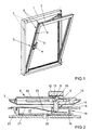
- FIG. 1 shows a window with a pivotable against a frame 1 wings 2 and with a drive rod fitting 3 in a tilted position.
- the espagnolette fitting 3 has a handle 4 for driving a hidden and longitudinally displaceable guided in the wing 2 drive rod 5.
- the window has a horizontal tilting axis and a vertical axis of rotation about which the wing 2 can pivot relative to the frame 1 in a tilted or rotational position.
- the wing 2 can be locked in the closed position via a plurality of closures 6 in the frame 1.
- the handle 4 is movable in different positions.
- the closures 6 each have a fastened to the frame 1 strike plate 7 and a driven by the handle 4 via the drive rod 5 closing member 8.
- FIG. 2 shows a sectional view through one of the closures 6 FIG. 1 in the closed position of the window in which the wing 2 is locked in the frame 1.
- the closing member 8 driven by the driving rod 5 is pivoted into the striking plate 7 and thus holds the wing 2 in the frame 1.
- the closing member 8 is pivotally mounted and is supported by a toothing 9 on a arranged in a fixed housing 10 setting tooth 11.
- One with the drive rod 5 off FIG. 1 connected slide 12 is connected to a bearing axis 13 of the closing member 8.
- the bearing shaft 13 is displaced during the drive of the drive rod 5, while the toothing 9 rolls on the adjusting tooth 11.
- the closing member 8 can be pivoted from the protruding position shown in a lying in the housing 10 position.
- the striking plate 7 has a base part 14 with a closing recess 15 for receiving the closing member 8 and a trough 16, with which it is screwed in the frame 1.
- the base 14 and the trough 16 define a cavity 17.
- the trough 16 has a peripheral aperture 18 for covering an opening 19 in the frame 1.
- a cover 20 is arranged in the cavity 17 of the striking plate 7.
- the cover 20 is made in one piece with a spring element 21 made of spring steel and biased in the direction of the closing recess 15.
- the unit of spring element 21 and cover 20 has a trained as latching attachment 22 in the strike plate 7. In the illustrated closed position of the espagnolette fitting 3, the cover 20 is pressed by the closing member 8 in the cavity 17.
- FIG. 3 shows a plan view of the strike plate 7 from FIG. 2 In this case, it can be seen that the unit of the spring element 21 and the cover element 20 completely closes off the trough 16 and is prestressed against the underside of the base part 14.
- the slide 23 for the closing member 8 FIG. 2 shown in dotted lines.
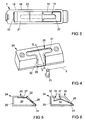
- FIG. 4 shows a strike plate 24 with a T-shaped locking recess 26.
- Such striking plates 24 are rigidly mounted on the drive rod 5 closing members 25 used.
- the drive rod 5 is shown only schematically.
- the closing recess 26 is completely closed by a cover member 27.
- the cover member 27 is made in one piece with a spring element 28 made of spring steel.
- FIG. 5 shows in a sectional view through the strike plate 24 FIG. 4 along the line V - V that a closing recess 26 receiving base 29 defines a cavity 30.
- the spring element 28 has a fastening 31 in the base part 29.
- a slide 32 is arranged for the closing member 25. The slide 32 is for clarity in FIG. 4 shown in phantom.
- FIG. 6 shows the shooting plate 24 from the FIGS. 4 and 5 after insertion of the closing member 25. It can be seen that the cover member 27 is pressed against the force of the spring element 28 in the cavity 30.
Description
Die Erfindung betrifft ein Schließblech für einen Treibstangenbeschlag eines Fensters, einer Fenstertür oder dergleichen mit einer Schließausnehmung zur Aufnahme eines beweglichen Schließgliedes und mit einem die Schließausnehmung aufnehmenden Grundteil.The invention relates to a strike plate for an espagnolette fitting a window, a French window or the like with a closing recess for receiving a movable closing member and with a the recess receiving base.
Ein solches Schließblech ist beispielsweise aus der
Aus der Praxis ist es bekannt, das Schließglied als starr auf der Treibstange befestigter Schließzapfen auszubilden. In diesem Falle wird das Schließglied beim Antrieb der Treibstange längs in die Schließausnehmung des Schließblechs eingeführt.From practice it is known to form the closing member as a rigidly mounted on the drive rod locking pin. In this case, the closing member when driving the drive rod is inserted longitudinally in the locking recess of the striking plate.
Nachteilig bei dem bekannten Schließblech ist, dass die Schließausnehmung hervorstehende Kanten aufweist, hinter denen sich Schmutz sammeln kann. Solche Kanten sind schwierig zu reinigen und stören auch optisch den Treibstangenbeschlag im geöffneten Zustand des Fensters, der Fenstertür oder dergleichen.A disadvantage of the known strike plate, that the closing recess has protruding edges, behind which can collect dirt. Such edges are difficult to clean and visually disturb the espagnolette in the open state of the window, the French door or the like.
Der Erfindung liegt das Problem zugrunde, ein Schließblech der eingangs genannten Art so zu gestalten, dass eine Verschmutzung besonders gering gehalten wird und dass es besonders einfach zu reinigen ist.The invention is based on the problem of designing a strike plate of the type mentioned above so that contamination is kept very low and that it is particularly easy to clean.
Dieses Problem wird erfindungsgemäß dadurch gelöst, dass ein bewegliches Abdeckelement in einer ersten Stellung die Schließausnehmung verschließt und in einer zweiten Stellung zur Ermöglichung des Einführens des Schließgliedes in die Schließausnehmung von der Schließausnehmung entfernt ist.This problem is inventively solved in that a movable cover member closes the closing recess in a first position and is removed in a second position for enabling the insertion of the closing member into the locking recess of the locking recess.
Durch diese Gestaltung verschließt das Abdeckelement die Schließausnehmung, wenn das Schließglied von der Schließausnehmung entfernt ist. Die von der Schließausnehmung entfernte Stellung des Schließgliedes entspricht der entriegelten Stellung des Treibstangenbeschlages, in der der Flügel von dem Rahmen weg geschwenkt werden kann. Da in dieser Stellung des Treibstangenbeschlages die Schließausnehmung von dem Abdeckelement verschlossen ist, kann kein Schmutz durch die Schließausnehmung in das Schließblech gelangen. Damit wird eine Verschmutzung des erfindungsgemäßen Schließblechs besonders gering gehalten. Weiterhin ist das Abdeckelement wesentlich einfacher zu reinigen als Kanten hinter der Schließausnehmung, so dass das erfindungsgemäße Schließblech besonders einfach zu reinigen ist.With this configuration, the cover member closes the lock recess when the lock member is removed from the lock recess. The remote from the locking recess position of the closing member corresponds to the unlocked position of the espagnolette fitting, in which the wing can be pivoted away from the frame. Since the closing recess is closed by the cover in this position of the espagnolette, no dirt can pass through the closing recess in the strike plate. This contamination of the striking plate according to the invention is kept particularly low. Furthermore, the cover is much easier to clean than edges behind the locking recess, so that the striking plate according to the invention is particularly easy to clean.
Zur Vereinfachung der Montage des erfindungsgemäßen Schließblechs trägt es bei, wenn das Abdeckelement mit dem Grundteil eine vormontierte bauliche Einheit bildet. Weiterhin lässt sich hierdurch das Abdeckelement untrennbar mit dem Grundteil verbinden und kann daher nicht verloren gehen.To simplify the assembly of the striker plate according to the invention, it is helpful if the cover element forms a preassembled structural unit with the base part. Furthermore, this allows the cover inseparably connect to the base and therefore can not be lost.
Der bauliche Aufwand zur Bewegung des Abdeckelementes lässt sich besonders gering halten, wenn das Abdeckelement von einem Federelement elastisch in die erste Stellung vorgespannt ist.The structural complexity for the movement of the cover can be kept particularly low when the cover is resiliently biased by a spring element in the first position.
Zur weiteren Verringerung der möglichen Verschmutzung des erfindungsgemäßen Schließblechs trägt es bei, wenn die Schließausnehmung in der Wandung eines Hohlraums angeordnet ist und wenn das Abdeckelement in der ersten Stellung an der Innenseite des Hohlraums anliegt.To further reduce the possible contamination of the strike plate according to the invention, it is beneficial if the closing recess is arranged in the wall of a cavity and if the cover element rests in the first position on the inside of the cavity.
Das erfindungsgemäße Schließblech lässt sich besonders kostengünstig fertigen, wenn das Abdeckelement und/oder das Federelement aus Federstahl gefertigt sind/ist.The striking plate according to the invention can be produced particularly cost-effectively, if the cover and / or the spring element are made of spring steel / is.
Zur Verringerung der Fertigungskosten des Abdeckelementes trägt es gemäß einer anderen vorteilhaften Weiterbildung der Erfindung bei, wenn das Abdeckelement und das Federelement einstückig gefertigt sind. Dies führt zudem zu einer starken Verringerung des Aufwandes der Montage des erfindungsgemäßen Schließblechs.To reduce the manufacturing cost of the cover it contributes according to another advantageous embodiment of the invention, when the cover and the spring element are made in one piece. This also leads to a strong reduction in the cost of mounting the strike plate according to the invention.
Zur Verringerung der Fertigungs- und Montagekosten des Federelementes trägt es gemäß einer anderen vorteilhaften Weiterbildung der Erfindung bei, wenn das Federelement aus ebenem Federstahl gefertigt und an dem Grundteil befestigt ist. Die Befestigung des Federelementes an dem die Schließausnehmung aufweisenden Bauteil kann im Schweißverfahren, durch Verrastung oder Vernietung erfolgen.To reduce the manufacturing and assembly costs of the spring element, it contributes according to another advantageous embodiment of the invention, when the spring element is made of flat spring steel and fixed to the base. The attachment of the spring element to the closing recess having component can be done in the welding process, by locking or riveting.
Die Bewegung des Abdeckelementes lässt sich gemäß einer anderen vorteilhaften Weiterbildung der Erfindung in Abhängigkeit von der Bewegung des Schließgliedes einfach koppeln, wenn das Abdeckelement eine Gleitbahn zwischen der Befestigung an dem Grundteil und einer zum Einführen des Schließgliedes vorgesehenen Einführöffnung der Schließausnehmung hat.The movement of the cover can be easily coupled according to another advantageous embodiment of the invention in response to the movement of the closing member when the cover a slideway between the attachment to the base and one for insertion has the closing member provided insertion opening of the closing recess.
Zur Vereinfachung der Reinigung des erfindungsgemäßen Schließblechs trägt es bei, wenn das Grundteil in einer Wanne angeordnet ist und wenn die Wanne eine umlaufende Blende zur Abdeckung einer Öffnung im Fenster oder in der Fenstertür aufweist. Durch diese Gestaltung lässt sich die Wanne in der Öffnung versenken. Diese Versenkbarkeit der Wanne mit dem die Schließausnehmung aufweisenden Grundteil bei gleichzeitigem Verschluss der Schließausnehmung ermöglicht eine glatte Gestaltung des das erfindungsgemäße Schließblech aufweisenden Fensters.To simplify the cleaning of the striking plate according to the invention, it is beneficial if the base is arranged in a trough and if the trough has a peripheral aperture to cover an opening in the window or in the French window. This design can sink the tub in the opening. This retractability of the trough with the base part having the closing recess with simultaneous closure of the closing recess enables a smooth design of the window having the striking plate according to the invention.
Die Erfindung lässt zahlreiche Ausführungsformen zu. Zur weiteren Verdeutlichung ihres Grundprinzips ist eine davon in der Zeichnung dargestellt und wird nachfolgend beschrieben. Diese zeigt in
- Fig. 1
- ein Fenster mit einem Treibstangenbeschlag und mit einem erfindungsgemäßen Schließblech,
- Fig. 2
- eine Schnittdarstellung durch einen Verschluss des Treibstangenbeschlages aus
Figur 1 - Fig. 3
- eine Draufsicht auf das Schließblech aus den
Figuren 1 und 2 - Fig. 4
- eine weitere Ausführungsform eines Schließblechs in einer perspektivischen Darstellung,
- Fig. 5
- eine Schnittdarstellung durch das Schließblech aus
Figur 4 - Fig. 6
- das Schließblech aus
Figur 5
- Fig. 1
- a window with a drive rod fitting and with a strike plate according to the invention,
- Fig. 2
- a sectional view through a closure of the espagnolette fitting
FIG. 1 with the strike plate in longitudinal section, - Fig. 3
- a plan view of the strike plate from the
Figures 1 and 2 . - Fig. 4
- a further embodiment of a striking plate in a perspective view,
- Fig. 5
- a sectional view through the strike plate
FIG. 4 along the line V - V, - Fig. 6
- the strike plate off
FIG. 5 with an inserted closing element.
Das Schließblech 7 hat ein Grundteil 14 mit einer Schließausnehmung 15 zur Aufnahme des Schließgliedes 8 und eine Wanne 16, mit der es in dem Rahmen 1 verschraubt ist. Das Grundteil 14 und die Wanne 16 begrenzen einen Hohlraum 17. Weiterhin hat die Wanne 16 eine umlaufende Blende 18 zur Abdeckung einer Öffnung 19 in dem Rahmen 1. In dem Hohlraum 17 des Schließblechs 7 ist ein Abdeckelement 20 angeordnet. Das Abdeckelement 20 ist einstückig mit einem aus Federstahl hergestellten Federelement 21 gefertigt und in Richtung der Schließausnehmung 15 vorgespannt. Die Einheit aus Federelement 21 und Abdeckelement 20 hat eine als Verrastung ausgebildete Befestigung 22 in dem Schließblech 7. In der dargestellten Schließstellung des Treibstangenbeschlages 3 ist das Abdeckelement 20 von dem Schließglied 8 in den Hohlraum 17 hineingedrückt. Verschwenkt man das Schließglied 8 in die zurückgezogene Stellung, wird das Abdeckelement 20 von der Kraft des Federelementes 21 gegen das Grundteil 14 mit der Schließausnehmung 15 gedrückt. Dabei wird die Schließausnehmung 15 verschlossen. Beim Verschwenken gleitet das Schließglied 8 über eine auf dem Abdeckelement 20 angeordnete Gleitbahn 23.The
Claims (9)
- Strike plate for an espagnolette fitting of a window, a French window or the like, comprising a locking recess for receiving a movable locking element and comprising a base part which receives the locking recess, characterised in that a movable cover element (20, 27) closes the locking recess (15, 26) when in a first position, and when in a second position is removed from the locking recess (15, 26) to enable the locking element (8, 25) to be inserted into the locking recess (15, 26).
- Strike plate according to claim 1, characterised in that the cover element (20, 27) forms a preassembled structural unit with the base part (14, 29).
- Strike plate according to either claim 1 or claim 2, characterised in that the cover element (20, 27) is resiliently biassed into the first position by a spring element (21, 28).
- Strike plate according to any of the preceding claims, characterised in that the locking recess (15, 26) is arranged in the wall of a hollow space (17, 30) and in that the cover element (20, 27) contacts the interior of the hollow space (17, 30) when in the first position.
- Strike plate according to either claim 3 or claim 4, characterised in that the cover element (20, 27) and/or the spring element (21, 28) is/are made from spring steel.
- Strike plate according to any of claims 3 to 5, characterised in that the cover element (20, 27) and the spring element (21, 28) are formed in one piece.
- Strike plate according to any of claims 3 to 6, characterised in that the spring element (21, 28) is made from planar spring steel and attached to the base part (14, 29).
- Strike plate according to any of the preceding claims, characterised in that the cover element (20, 27) comprises a sliding channel (23, 32) between the attachment (22, 31) to the base part (14, 29) and an insertion opening of the locking recess (15, 26) for inserting the locking element (8, 25).
- Strike plate according to any of the preceding claims, characterised in that the base part (14) is arranged in a trough (16) and in that the trough (16) comprises a surround (18) for covering an opening (19) in the window or French window.
Priority Applications (1)
| Application Number | Priority Date | Filing Date | Title |
|---|---|---|---|
| PL09176919T PL2199508T3 (en) | 2008-12-16 | 2009-11-24 | Strike plate for a connecting rod fitting |
Applications Claiming Priority (1)
| Application Number | Priority Date | Filing Date | Title |
|---|---|---|---|
| DE102008054725A DE102008054725A1 (en) | 2008-12-16 | 2008-12-16 | Striker plate for an espagnolette fitting |
Publications (3)
| Publication Number | Publication Date |
|---|---|
| EP2199508A2 EP2199508A2 (en) | 2010-06-23 |
| EP2199508A3 EP2199508A3 (en) | 2011-09-14 |
| EP2199508B1 true EP2199508B1 (en) | 2013-01-09 |
Family
ID=41819252
Family Applications (1)
| Application Number | Title | Priority Date | Filing Date |
|---|---|---|---|
| EP09176919A Not-in-force EP2199508B1 (en) | 2008-12-16 | 2009-11-24 | Strike plate for a connecting rod fitting |
Country Status (4)
| Country | Link |
|---|---|
| EP (1) | EP2199508B1 (en) |
| DE (1) | DE102008054725A1 (en) |
| ES (1) | ES2400984T3 (en) |
| PL (1) | PL2199508T3 (en) |
Family Cites Families (3)
| Publication number | Priority date | Publication date | Assignee | Title |
|---|---|---|---|---|
| DE19856451C2 (en) * | 1998-12-09 | 2001-12-06 | Siegenia Frank Kg | Locking device |
| DE102005000192A1 (en) * | 2005-12-20 | 2007-06-21 | Aug. Winkhaus Gmbh & Co. Kg | Closure for drive bolt fitment of casement windows and doors has two closure parts and a protruding sensor to detect when casement is in frame to move second closure part from retracted to protruding position |
| DE102006000280A1 (en) | 2006-06-09 | 2007-12-13 | Aug. Winkhaus Gmbh & Co. Kg | Locking device for drive rod fitting for locking e.g. window or door panel pivotable relative to frame has locking element movably guided in longitudinal guide parallel to direction of motion of drive rod into at least one of two positions |
-
2008
- 2008-12-16 DE DE102008054725A patent/DE102008054725A1/en not_active Withdrawn
-
2009
- 2009-11-24 PL PL09176919T patent/PL2199508T3/en unknown
- 2009-11-24 EP EP09176919A patent/EP2199508B1/en not_active Not-in-force
- 2009-11-24 ES ES09176919T patent/ES2400984T3/en active Active
Also Published As
| Publication number | Publication date |
|---|---|
| DE102008054725A1 (en) | 2010-06-17 |
| ES2400984T3 (en) | 2013-04-16 |
| PL2199508T3 (en) | 2013-06-28 |
| EP2199508A2 (en) | 2010-06-23 |
| EP2199508A3 (en) | 2011-09-14 |
Similar Documents
| Publication | Publication Date | Title |
|---|---|---|
| EP3464764B1 (en) | Motor vehicle lock | |
| DE202005006942U1 (en) | Sliding door for a motor vehicle | |
| EP1617031A2 (en) | Sliding door for a vehicle | |
| EP2692969B1 (en) | Gear of a drive rod fixture, drive rod fixture with such a gear and window, door or similar with such a drive rod fixture | |
| EP2816178B1 (en) | Fitting for windows or doors | |
| DE202008006506U1 (en) | Catcher for a tilt-and-turn door | |
| EP0485767A1 (en) | Lock for the wing, especially the sliding wing, of a window, door etc. | |
| DE19924028A1 (en) | Vehicle door; has twist lock fixed to rear edge area and operated from inside and outside by control or handle at front edge connected to common control unit by Bowden cables | |
| EP2199508B1 (en) | Strike plate for a connecting rod fitting | |
| DE202008009023U1 (en) | Closure for windows or doors | |
| DE202007013330U1 (en) | Motor vehicle lock | |
| EP3553260B1 (en) | Striker insert with day position for conditional release of a lock striker plate of a door-locking mechanism | |
| DE202009007430U1 (en) | hardware system | |
| EP3269902B1 (en) | Operating assembly for a building closure, corresponding building closure, kit for the preparation of building closures and method of equipping a building closure | |
| DE10252884A1 (en) | Espagnolette fitting for an embossed sash of a double-leaf, timber without window or door with an espagnolette drive | |
| EP1757759B1 (en) | Fitting component for an espagnolette fitting | |
| EP3118401A1 (en) | Lock bolt for the edge of a wing | |
| AT509464B1 (en) | LOCK | |
| DE102016202377A1 (en) | Fitting arrangement for connecting a sliding and tiltable sash | |
| DE102010055397B4 (en) | Locking/unlocking device for a sliding door and door equipped with such a device | |
| DE102016004915B3 (en) | Fitting for a window, method for producing the fitting and corresponding window | |
| EP1816291A2 (en) | Drive device for a boltable window leaf in a frame | |
| EP3018269B1 (en) | Handle assembly for a window or the like and window or the like with handle assembly | |
| DE202011103191U1 (en) | Self-locking lock | |
| EP2320013B1 (en) | Fitting with a reversing gear |
Legal Events
| Date | Code | Title | Description |
|---|---|---|---|
| PUAI | Public reference made under article 153(3) epc to a published international application that has entered the european phase |
Free format text: ORIGINAL CODE: 0009012 |
|
| AK | Designated contracting states |
Kind code of ref document: A2 Designated state(s): AT BE BG CH CY CZ DE DK EE ES FI FR GB GR HR HU IE IS IT LI LT LU LV MC MK MT NL NO PL PT RO SE SI SK SM TR |
|
| AX | Request for extension of the european patent |
Extension state: AL BA RS |
|
| PUAL | Search report despatched |
Free format text: ORIGINAL CODE: 0009013 |
|
| AK | Designated contracting states |
Kind code of ref document: A3 Designated state(s): AT BE BG CH CY CZ DE DK EE ES FI FR GB GR HR HU IE IS IT LI LT LU LV MC MK MT NL NO PL PT RO SE SI SK SM TR |
|
| AX | Request for extension of the european patent |
Extension state: AL BA RS |
|
| RIC1 | Information provided on ipc code assigned before grant |
Ipc: E05C 9/18 20060101ALI20110805BHEP Ipc: E05C 9/00 20060101AFI20110805BHEP |
|
| 17P | Request for examination filed |
Effective date: 20111220 |
|
| GRAP | Despatch of communication of intention to grant a patent |
Free format text: ORIGINAL CODE: EPIDOSNIGR1 |
|
| RIC1 | Information provided on ipc code assigned before grant |
Ipc: E05C 9/00 20060101AFI20120626BHEP Ipc: E05C 9/18 20060101ALI20120626BHEP |
|
| GRAS | Grant fee paid |
Free format text: ORIGINAL CODE: EPIDOSNIGR3 |
|
| GRAA | (expected) grant |
Free format text: ORIGINAL CODE: 0009210 |
|
| AK | Designated contracting states |
Kind code of ref document: B1 Designated state(s): AT BE BG CH CY CZ DE DK EE ES FI FR GB GR HR HU IE IS IT LI LT LU LV MC MK MT NL NO PL PT RO SE SI SK SM TR |
|
| REG | Reference to a national code |
Ref country code: GB Ref legal event code: FG4D Free format text: NOT ENGLISH |
|
| REG | Reference to a national code |
Ref country code: AT Ref legal event code: REF Ref document number: 592871 Country of ref document: AT Kind code of ref document: T Effective date: 20130115 Ref country code: CH Ref legal event code: EP |
|
| REG | Reference to a national code |
Ref country code: IE Ref legal event code: FG4D Free format text: LANGUAGE OF EP DOCUMENT: GERMAN |
|
| REG | Reference to a national code |
Ref country code: DE Ref legal event code: R096 Ref document number: 502009005955 Country of ref document: DE Effective date: 20130307 |
|
| REG | Reference to a national code |
Ref country code: ES Ref legal event code: FG2A Ref document number: 2400984 Country of ref document: ES Kind code of ref document: T3 Effective date: 20130416 |
|
| PG25 | Lapsed in a contracting state [announced via postgrant information from national office to epo] |
Ref country code: SI Free format text: LAPSE BECAUSE OF FAILURE TO SUBMIT A TRANSLATION OF THE DESCRIPTION OR TO PAY THE FEE WITHIN THE PRESCRIBED TIME-LIMIT Effective date: 20130109 |
|
| REG | Reference to a national code |
Ref country code: NL Ref legal event code: VDEP Effective date: 20130109 |
|
| REG | Reference to a national code |
Ref country code: LT Ref legal event code: MG4D |
|
| REG | Reference to a national code |
Ref country code: PL Ref legal event code: T3 |
|
| PG25 | Lapsed in a contracting state [announced via postgrant information from national office to epo] |
Ref country code: LT Free format text: LAPSE BECAUSE OF FAILURE TO SUBMIT A TRANSLATION OF THE DESCRIPTION OR TO PAY THE FEE WITHIN THE PRESCRIBED TIME-LIMIT Effective date: 20130109 Ref country code: SE Free format text: LAPSE BECAUSE OF FAILURE TO SUBMIT A TRANSLATION OF THE DESCRIPTION OR TO PAY THE FEE WITHIN THE PRESCRIBED TIME-LIMIT Effective date: 20130109 Ref country code: IS Free format text: LAPSE BECAUSE OF FAILURE TO SUBMIT A TRANSLATION OF THE DESCRIPTION OR TO PAY THE FEE WITHIN THE PRESCRIBED TIME-LIMIT Effective date: 20130509 Ref country code: BG Free format text: LAPSE BECAUSE OF FAILURE TO SUBMIT A TRANSLATION OF THE DESCRIPTION OR TO PAY THE FEE WITHIN THE PRESCRIBED TIME-LIMIT Effective date: 20130409 Ref country code: NO Free format text: LAPSE BECAUSE OF FAILURE TO SUBMIT A TRANSLATION OF THE DESCRIPTION OR TO PAY THE FEE WITHIN THE PRESCRIBED TIME-LIMIT Effective date: 20130409 |
|
| PG25 | Lapsed in a contracting state [announced via postgrant information from national office to epo] |
Ref country code: GR Free format text: LAPSE BECAUSE OF FAILURE TO SUBMIT A TRANSLATION OF THE DESCRIPTION OR TO PAY THE FEE WITHIN THE PRESCRIBED TIME-LIMIT Effective date: 20130410 Ref country code: PT Free format text: LAPSE BECAUSE OF FAILURE TO SUBMIT A TRANSLATION OF THE DESCRIPTION OR TO PAY THE FEE WITHIN THE PRESCRIBED TIME-LIMIT Effective date: 20130509 Ref country code: LV Free format text: LAPSE BECAUSE OF FAILURE TO SUBMIT A TRANSLATION OF THE DESCRIPTION OR TO PAY THE FEE WITHIN THE PRESCRIBED TIME-LIMIT Effective date: 20130109 Ref country code: NL Free format text: LAPSE BECAUSE OF FAILURE TO SUBMIT A TRANSLATION OF THE DESCRIPTION OR TO PAY THE FEE WITHIN THE PRESCRIBED TIME-LIMIT Effective date: 20130109 Ref country code: FI Free format text: LAPSE BECAUSE OF FAILURE TO SUBMIT A TRANSLATION OF THE DESCRIPTION OR TO PAY THE FEE WITHIN THE PRESCRIBED TIME-LIMIT Effective date: 20130109 |
|
| PG25 | Lapsed in a contracting state [announced via postgrant information from national office to epo] |
Ref country code: HR Free format text: LAPSE BECAUSE OF FAILURE TO SUBMIT A TRANSLATION OF THE DESCRIPTION OR TO PAY THE FEE WITHIN THE PRESCRIBED TIME-LIMIT Effective date: 20130109 |
|
| PG25 | Lapsed in a contracting state [announced via postgrant information from national office to epo] |
Ref country code: EE Free format text: LAPSE BECAUSE OF FAILURE TO SUBMIT A TRANSLATION OF THE DESCRIPTION OR TO PAY THE FEE WITHIN THE PRESCRIBED TIME-LIMIT Effective date: 20130109 Ref country code: CZ Free format text: LAPSE BECAUSE OF FAILURE TO SUBMIT A TRANSLATION OF THE DESCRIPTION OR TO PAY THE FEE WITHIN THE PRESCRIBED TIME-LIMIT Effective date: 20130109 Ref country code: RO Free format text: LAPSE BECAUSE OF FAILURE TO SUBMIT A TRANSLATION OF THE DESCRIPTION OR TO PAY THE FEE WITHIN THE PRESCRIBED TIME-LIMIT Effective date: 20130109 Ref country code: SK Free format text: LAPSE BECAUSE OF FAILURE TO SUBMIT A TRANSLATION OF THE DESCRIPTION OR TO PAY THE FEE WITHIN THE PRESCRIBED TIME-LIMIT Effective date: 20130109 Ref country code: DK Free format text: LAPSE BECAUSE OF FAILURE TO SUBMIT A TRANSLATION OF THE DESCRIPTION OR TO PAY THE FEE WITHIN THE PRESCRIBED TIME-LIMIT Effective date: 20130109 |
|
| PLBE | No opposition filed within time limit |
Free format text: ORIGINAL CODE: 0009261 |
|
| STAA | Information on the status of an ep patent application or granted ep patent |
Free format text: STATUS: NO OPPOSITION FILED WITHIN TIME LIMIT |
|
| PG25 | Lapsed in a contracting state [announced via postgrant information from national office to epo] |
Ref country code: CY Free format text: LAPSE BECAUSE OF FAILURE TO SUBMIT A TRANSLATION OF THE DESCRIPTION OR TO PAY THE FEE WITHIN THE PRESCRIBED TIME-LIMIT Effective date: 20130109 |
|
| 26N | No opposition filed |
Effective date: 20131010 |
|
| REG | Reference to a national code |
Ref country code: DE Ref legal event code: R097 Ref document number: 502009005955 Country of ref document: DE Effective date: 20131010 |
|
| REG | Reference to a national code |
Ref country code: CH Ref legal event code: PL |
|
| GBPC | Gb: european patent ceased through non-payment of renewal fee |
Effective date: 20131124 |
|
| PG25 | Lapsed in a contracting state [announced via postgrant information from national office to epo] |
Ref country code: CH Free format text: LAPSE BECAUSE OF NON-PAYMENT OF DUE FEES Effective date: 20131130 Ref country code: LI Free format text: LAPSE BECAUSE OF NON-PAYMENT OF DUE FEES Effective date: 20131130 Ref country code: MC Free format text: LAPSE BECAUSE OF FAILURE TO SUBMIT A TRANSLATION OF THE DESCRIPTION OR TO PAY THE FEE WITHIN THE PRESCRIBED TIME-LIMIT Effective date: 20130109 |
|
| REG | Reference to a national code |
Ref country code: IE Ref legal event code: MM4A |
|
| PG25 | Lapsed in a contracting state [announced via postgrant information from national office to epo] |
Ref country code: IE Free format text: LAPSE BECAUSE OF NON-PAYMENT OF DUE FEES Effective date: 20131124 |
|
| PG25 | Lapsed in a contracting state [announced via postgrant information from national office to epo] |
Ref country code: GB Free format text: LAPSE BECAUSE OF NON-PAYMENT OF DUE FEES Effective date: 20131124 |
|
| PGFP | Annual fee paid to national office [announced via postgrant information from national office to epo] |
Ref country code: ES Payment date: 20141222 Year of fee payment: 6 Ref country code: TR Payment date: 20141105 Year of fee payment: 6 |
|
| PGFP | Annual fee paid to national office [announced via postgrant information from national office to epo] |
Ref country code: PL Payment date: 20141118 Year of fee payment: 6 |
|
| PG25 | Lapsed in a contracting state [announced via postgrant information from national office to epo] |
Ref country code: SM Free format text: LAPSE BECAUSE OF FAILURE TO SUBMIT A TRANSLATION OF THE DESCRIPTION OR TO PAY THE FEE WITHIN THE PRESCRIBED TIME-LIMIT Effective date: 20130109 |
|
| PGFP | Annual fee paid to national office [announced via postgrant information from national office to epo] |
Ref country code: BE Payment date: 20141127 Year of fee payment: 6 |
|
| PG25 | Lapsed in a contracting state [announced via postgrant information from national office to epo] |
Ref country code: HU Free format text: LAPSE BECAUSE OF FAILURE TO SUBMIT A TRANSLATION OF THE DESCRIPTION OR TO PAY THE FEE WITHIN THE PRESCRIBED TIME-LIMIT; INVALID AB INITIO Effective date: 20091124 Ref country code: MK Free format text: LAPSE BECAUSE OF FAILURE TO SUBMIT A TRANSLATION OF THE DESCRIPTION OR TO PAY THE FEE WITHIN THE PRESCRIBED TIME-LIMIT Effective date: 20130109 Ref country code: LU Free format text: LAPSE BECAUSE OF NON-PAYMENT OF DUE FEES Effective date: 20131124 |
|
| PG25 | Lapsed in a contracting state [announced via postgrant information from national office to epo] |
Ref country code: MT Free format text: LAPSE BECAUSE OF FAILURE TO SUBMIT A TRANSLATION OF THE DESCRIPTION OR TO PAY THE FEE WITHIN THE PRESCRIBED TIME-LIMIT Effective date: 20130109 |
|
| REG | Reference to a national code |
Ref country code: FR Ref legal event code: PLFP Year of fee payment: 7 |
|
| PGFP | Annual fee paid to national office [announced via postgrant information from national office to epo] |
Ref country code: IT Payment date: 20151124 Year of fee payment: 7 |
|
| PGFP | Annual fee paid to national office [announced via postgrant information from national office to epo] |
Ref country code: FR Payment date: 20151130 Year of fee payment: 7 |
|
| REG | Reference to a national code |
Ref country code: ES Ref legal event code: FD2A Effective date: 20170102 |
|
| PG25 | Lapsed in a contracting state [announced via postgrant information from national office to epo] |
Ref country code: ES Free format text: LAPSE BECAUSE OF NON-PAYMENT OF DUE FEES Effective date: 20151125 |
|
| PG25 | Lapsed in a contracting state [announced via postgrant information from national office to epo] |
Ref country code: PL Free format text: LAPSE BECAUSE OF NON-PAYMENT OF DUE FEES Effective date: 20151124 |
|
| PG25 | Lapsed in a contracting state [announced via postgrant information from national office to epo] |
Ref country code: BE Free format text: LAPSE BECAUSE OF NON-PAYMENT OF DUE FEES Effective date: 20151130 |
|
| REG | Reference to a national code |
Ref country code: FR Ref legal event code: ST Effective date: 20170731 |
|
| PG25 | Lapsed in a contracting state [announced via postgrant information from national office to epo] |
Ref country code: TR Free format text: LAPSE BECAUSE OF NON-PAYMENT OF DUE FEES Effective date: 20151124 |
|
| PG25 | Lapsed in a contracting state [announced via postgrant information from national office to epo] |
Ref country code: IT Free format text: LAPSE BECAUSE OF NON-PAYMENT OF DUE FEES Effective date: 20161124 Ref country code: FR Free format text: LAPSE BECAUSE OF NON-PAYMENT OF DUE FEES Effective date: 20161130 |
|
| PGFP | Annual fee paid to national office [announced via postgrant information from national office to epo] |
Ref country code: AT Payment date: 20171128 Year of fee payment: 9 |
|
| PGFP | Annual fee paid to national office [announced via postgrant information from national office to epo] |
Ref country code: DE Payment date: 20190131 Year of fee payment: 10 |
|
| REG | Reference to a national code |
Ref country code: AT Ref legal event code: MM01 Ref document number: 592871 Country of ref document: AT Kind code of ref document: T Effective date: 20181124 |
|
| PG25 | Lapsed in a contracting state [announced via postgrant information from national office to epo] |
Ref country code: AT Free format text: LAPSE BECAUSE OF NON-PAYMENT OF DUE FEES Effective date: 20181124 |
|
| REG | Reference to a national code |
Ref country code: DE Ref legal event code: R119 Ref document number: 502009005955 Country of ref document: DE |
|
| PG25 | Lapsed in a contracting state [announced via postgrant information from national office to epo] |
Ref country code: DE Free format text: LAPSE BECAUSE OF NON-PAYMENT OF DUE FEES Effective date: 20200603 |