EP2320013B1 - Fitting with a reversing gear - Google Patents
Fitting with a reversing gear Download PDFInfo
- Publication number
- EP2320013B1 EP2320013B1 EP09175555A EP09175555A EP2320013B1 EP 2320013 B1 EP2320013 B1 EP 2320013B1 EP 09175555 A EP09175555 A EP 09175555A EP 09175555 A EP09175555 A EP 09175555A EP 2320013 B1 EP2320013 B1 EP 2320013B1
- Authority
- EP
- European Patent Office
- Prior art keywords
- drive rod
- movement
- fitting
- bar element
- locking
- Prior art date
- Legal status (The legal status is an assumption and is not a legal conclusion. Google has not performed a legal analysis and makes no representation as to the accuracy of the status listed.)
- Not-in-force
Links
Images

Classifications
-
- E—FIXED CONSTRUCTIONS
- E05—LOCKS; KEYS; WINDOW OR DOOR FITTINGS; SAFES
- E05C—BOLTS OR FASTENING DEVICES FOR WINGS, SPECIALLY FOR DOORS OR WINDOWS
- E05C9/00—Arrangements of simultaneously actuated bolts or other securing devices at well-separated positions on the same wing
- E05C9/04—Arrangements of simultaneously actuated bolts or other securing devices at well-separated positions on the same wing with two sliding bars moved in opposite directions when fastening or unfastening
- E05C9/041—Arrangements of simultaneously actuated bolts or other securing devices at well-separated positions on the same wing with two sliding bars moved in opposite directions when fastening or unfastening with rack and pinion mechanism
-
- E—FIXED CONSTRUCTIONS
- E05—LOCKS; KEYS; WINDOW OR DOOR FITTINGS; SAFES
- E05C—BOLTS OR FASTENING DEVICES FOR WINGS, SPECIALLY FOR DOORS OR WINDOWS
- E05C9/00—Arrangements of simultaneously actuated bolts or other securing devices at well-separated positions on the same wing
- E05C9/06—Arrangements of simultaneously actuated bolts or other securing devices at well-separated positions on the same wing with three or more sliding bars
- E05C9/063—Arrangements of simultaneously actuated bolts or other securing devices at well-separated positions on the same wing with three or more sliding bars extending along three or more sides of the wing or frame
- E05C9/066—Locks for windows or doors specially adapted for tilt and turn
Definitions
- the invention relates to a fitting for a window, a door or the like with a mosöffen- and tiltable wings, with a drive rod which is driven in the longitudinal direction of the drive rod and with a locking element which occupies different positions depending on the position of the drive rod.
- a locking element is moved by a drive rod.
- the drive rod is usually driven by a handle, such as a handle, wherein the handle and thus the drive rod and a coupled locking element can generally assume three defined positions, namely a position corresponding to a locking of the wing (locking position) , a second position in which the wing can be opened in rotation (rotational opening position) and a third position in which the wing can tilt open (tilting position).
- the drive rod is driven in the direction of its longitudinal direction.
- a locking element which is connected to the drive rod or is arranged on this, performs a movement in the same direction as the drive rod. If the locking element for a locking position and a tilted position cooperate with the same closing piece, a very large closing piece must be selected so that the locking element can interact with the closing piece after its movement from the locking position into the tilting position.
- a striker cooperates with the latch member in a locking position and another striker cooperates with the latch member in a tilted position.
- Object of the present invention is to provide a fitting for a window, a door or the like, with the smaller or fewer strikers can be used, yet a locking, pivoting open and tilt-open a wing is made possible.
- the fitting according to the invention thus at least partially realized a reverse gear. It is with the fitting according to the invention possible that the locking element cooperates with an associated closing piece in a similar position of the locking element both for locking the wing and for tilting open the wing. In particular, this makes it possible to manage only with a locking piece associated with a locking element. It is also possible to reduce the size of the striker. The movement of the locking element can be done on a smaller total distance.
- the drive rod and the locking element or a fitting connected to the locking element each in a section as a rack, in particular ladder rack, are formed and the coupling element is designed as a cooperating gear.
- the coupling element can be arranged between the drive rod and the locking element or the fitting part connected to the locking element. This can be effected in a simple manner that the movement of the drive rod is converted in one direction in an opposite direction of the locking element.
- the toothed wheel is rotatably arranged on a fitting part, in particular in a housing.
- the gear may have an axis of rotation which is rotatably mounted in two opposite recesses of a housing.
- the gear can be arranged in the housing stationary, so if it is rotatably arranged, perform no movement in the direction of the espagnolette movement.
- a decoupling section is provided on the drive rod, which is movable past the coupling element during a movement of the drive rod, without that Coupling element is in operative connection with the drive rod.
- the blocking means in particular depending on the relative position of drive rod and locking element, be activated.
- the fitting is designed so that when activated blocking means, the opposite movement of the drive rod and locking element causing coupling is disabled by means of the coupling element. If, on the other hand, the blocking means are not activated, then the coupling of drive rod and locking element or fitting part, which is connected to the locking element, takes place via the coupling element, so that an opposite movement is realized.
- activated blocking means is a rectified movement of drive rod and locking element, when the drive rod is driven.
- the blocking means comprise a blocking element movable transversely to the direction of movement of the drive rod.
- both the drive rod and a locking element connected to the fitting part or the locking element penetrates and thereby determines their relative position. It is understood that the drive rod and the locking element or the fitting part corresponding recesses, in particular breakthroughs, so that the locking element drive rod and fitting or locking element can protrude.
- the blocking element cooperates with a control cam which determines the movement of the locking element transversely to the direction of movement of the drive rod.
- the blocking means comprise the coupling element and a turnstile of the coupling element. If the coupling element is arranged rotatably on the turnstile and yet with both the drive rod and with the locking element or the fitting, which is connected to the locking element, is engaged, an opposite movement of the drive rod and locking element is prevented. Thus, it can be effected in a simple manner that the locking element is moved in the same direction as the drive rod.
- the coupling element in a rotationally locked state relative to a fitting part, on which it is rotatably arranged in the non-rotationally locked state, along a guide in the drive rod movement direction is movable.
- the leadership have two parallel side walls along which the turnstile can slide.
- the turnstile cooperates with a guide, in particular a housing.
- a guide in particular a housing.
- a recess for the turnstile In the region of one end of the guide may be provided a recess for the turnstile, so that the coupling element is rotatable.
- the scope of the invention also includes a window, a door or the like with a wing rotatable and tiltable with respect to a fixed skirt and with a fitting according to the invention, the drive rod being in one direction from a locking position in which the locking element cooperates with a closing piece. in a position permitting a rotary opening of the wing and in a tilting position of the wing permitting position is movable, and wherein the locking element during a part of the movement of the drive rod performs a movement in the opposite direction.
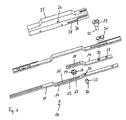
- the FIG. 1 shows an exploded view of a fitting 10.
- the fitting 10 comprises a drive rod 11, which has a toothed rod 13, in particular ladder rack, trained portion and a decoupling portion 14 in a cranked region 12.
- the decoupling section 14 essentially has a slot 15.
- the rack 13 cooperates with a gear formed as a coupling element 16, which is arranged between the drive rod 11 and a fitting part 17, which also has a rack 18, in particular a ladder rack.
- a pin locking element 19 can be fastened.
- the locking element 19 extends through a cuff rail 20 and a sliding member 21 and is connected at its free end 22 at a position 23 to the fitting 17, in particular riveted.
- the drive rod 11, the fitting part 17, the faceplate 20 and the coupling element 16 are at least partially in a housing trained fitting part 25 is arranged.
- the fitting part 25 has recesses 26 in which the coupling element 16 with axial projections 27, which serve as a rotation axis, is mounted.
- the fitting part 25 has a control cam 28, which is designed as a backdrop on.
- a locking means 29 is guided with a bolt 30.
- the locking means 29 extends through the recess 31 of the drive rod 11 and in a certain relative position of drive rod 11 and fitting 17 and the recess 32 of the fitting part 17.
- the locking means 29 both recesses 31, 32 of the drive rod 11 and the fitting 17 penetrates, so they are coupled together. A relative movement, seen in the longitudinal direction of the drive rod 11, is therefore not possible.
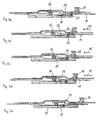
- the operation of the fitting 10 according to the invention is based on the FIGS. 2a to 2e explained.
- the in the FIG. 2a illustrated situation corresponds to a position of the fitting with locked window or door leaf.
- the locking element 29 extends through both the drive rod 11 and the fitting part 17.
- the locking means 29 is located in an outer right position of the control cam 28.
- the coupling element 16 is only with the rack 18 into engagement. With respect to the drive rod 11, it is arranged in Entkoppelabêt 14 and thus does not interact with the drive rod 11.
- the drive rod 11 is moved to the left in the direction of arrow 35, as shown in the FIG. 2b is indicated, the fitting part 17 is taken due to the coupling with the locking element 29 and thus the locking element 19 in the direction of movement of the drive rod.
- the in the FIG. 2a shown situation corresponds to a locking position of the locking element 19.
- the in the Figure 2c shown situation corresponds to a position of the locking element 19, which allows a rotational opening of the wing.
- the FIG. 2e illustrates a situation in which the locking element 19 assumes a position that allows tilt opening of a door or window sash. It can be seen that the locking element 19 always performs a very small stroke and during a part of the movement of the drive rod 11 in the direction of arrow 35 is moved in the same direction and during a part of the movement of the drive rod 11 in the direction of arrow 35 opposite direction is moved.
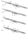
- FIG. 3 shows an exploded view of an alternative embodiment of a fitting 40 according to the invention.
- a drive rod 41 has a rack 42, which is designed as a ladder rack on. This cooperates with a coupling element 43, whose teeth project through a slot 44 of a faceplate 45 in order to come into engagement with the rack 42.
- the coupling element 43 is arranged in a two-part housing with the housing parts 46, 47. In this case, the axial projections 48 of the coupling element 43, which serve as a rotation axis, in the guides 49, 50 of the housing parts 46, 47 are arranged.
- the coupling element 43 also interacts with a locking element 51, which has a rack 52, which is designed as a ladder rack.
- the locking element 51 is likewise guided in the housing 46, 47, in particular in the recess 53.
- the coupling element 43 has a turnstile 60, which can be guided in the orientation shown in the guide 49 and thus allows a displacement of the coupling element 43 in the longitudinal direction of the drive rod 41.
- a rotational movement of the coupling element 43 is only possible when the turnstile 60 is located in the region of the recess 61 at the end of the guide 49.
- the guide 49 has opposite surfaces 62, 63, which cooperate with the surfaces 64 of the turnstile 60.
- the surfaces 64 may slide along the surfaces 62, 63.
Description
Die Erfindung betrifft einen Beschlag für ein Fenster, eine Tür oder dergleichen mit einem drehöffen- und kippbaren Flügel, mit einer Treibstange, die in Längsrichtung der Treibstange antreibbar ist und mit einem Riegelelement, welches in Abhängigkeit der Stellung der Treibstange unterschiedliche Stellungen einnimmt.The invention relates to a fitting for a window, a door or the like with a drehöffen- and tiltable wings, with a drive rod which is driven in the longitudinal direction of the drive rod and with a locking element which occupies different positions depending on the position of the drive rod.
Es sind Fenster, Türen oder dergleichen bekannt, die einen drehöffen- und kippbaren Flügel aufweisen. Bei Beschlägen dieser Fenster oder Türen ist vorgesehen, dass ein Riegelelement durch eine Treibstange bewegt wird. Die Treibstange wird in der Regel durch eine Handhabe, beispielsweise einen Griff, angetrieben, wobei der Griff und damit die Treibstange und ein damit gekoppeltes Riegelelement in der Regel drei definierte Stellungen einnehmen können, nämlich eine Stellung, die einer Verriegelung des Flügels entspricht (Verriegelungsstellung), einer zweiten Stellung, in der sich der Flügel drehöffnen lässt (Drehöffnungsstellung) und einer dritten Stellung, in der sich der Flügel kippöffnen lässt (Kippstellung). Bei einer Bewegung der Handhabe von der Verriegelungsstellung üben die Drehöffnungsstellung bis in die Kippstellung wird die Treibstange in Richtung ihrer Längsrichtung angetrieben. Dies bedeutet, dass auch ein Riegelelement, welches mit der Treibstange in Verbindung steht bzw. an dieser angeordnet ist, eine Bewegung in der gleichen Richtung wie die Treibstange ausführt. Soll das Riegelelement für eine Verriegelungsstellung und eine Kippstellung mit demselben Schließstück zusammenwirken, muss ein sehr großes Schließstück gewählt werden, so dass das Riegelelement nach seiner Bewegung von der Verriegelungsstellung in die Kippstellung mit dem Schließstück zusammenwirken kann. Alternativ ist es bekannt, zwei Schließstücke vorzusehen, wobei ein Schließstück mit dem Riegelelement in einer Verriegelungsstellung zusammenwirkt und ein anderes Schließstück mit dem Riegelelement in einer Kippstellung zusammenwirkt.There are windows, doors or the like are known, which have a drehöffen- and tiltable wing. When fittings of these windows or doors is provided that a locking element is moved by a drive rod. The drive rod is usually driven by a handle, such as a handle, wherein the handle and thus the drive rod and a coupled locking element can generally assume three defined positions, namely a position corresponding to a locking of the wing (locking position) , a second position in which the wing can be opened in rotation (rotational opening position) and a third position in which the wing can tilt open (tilting position). In a movement of the handle from the locking position practicing the rotary opening position to the tilted position, the drive rod is driven in the direction of its longitudinal direction. This means that a locking element, which is connected to the drive rod or is arranged on this, performs a movement in the same direction as the drive rod. If the locking element for a locking position and a tilted position cooperate with the same closing piece, a very large closing piece must be selected so that the locking element can interact with the closing piece after its movement from the locking position into the tilting position. Alternatively, it is known to provide two strikers, wherein a striker cooperates with the latch member in a locking position and another striker cooperates with the latch member in a tilted position.
Aus der
Aus der
In der
Aufgabe der vorliegenden Erfindung ist es, einen Beschlag für ein Fenster, eine Tür oder dergleichen bereitzustellen, mit dem kleinere oder weniger Schließstücke verwendet werden können und dennoch ein Verriegeln, Drehöffnen und Kippöffnen eines Flügels ermöglicht wird.Object of the present invention is to provide a fitting for a window, a door or the like, with the smaller or fewer strikers can be used, yet a locking, pivoting open and tilt-open a wing is made possible.
Gelöst wird diese Aufgabe erfindungsgemäß durch einen Beschlag mit den Merkmalen des Anspruchs 1 und einen Beschlag mit den Merkmalen des Anspruchs 8. Durch den erfindungsgemäßen Beschlag wird somit zumindest teilweise ein Umkehrgetriebe realisiert. Mit dem erfindungsgemäßen Beschlag ist es möglich, dass das Riegelelement mit einem zugeordneten Schließstück in ähnlicher Stellung des Riegelelements sowohl zum Verriegeln des Flügels als auch zum Kippöffnen des Flügels zusammenwirkt. Insbesondere ist es dadurch möglich, nur mit einem einem Riegelelement zugeordneten Schließstück auszukommen. Auch ist es möglich, die Größe des Schließstücks zu reduzieren. Die Bewegung des Riegelelements kann auf kleinerer Gesamtstrecke erfolgen.This object is achieved according to the invention by a fitting with the features of claim 1 and a fitting with the features of claim 8. The fitting according to the invention thus at least partially realized a reverse gear. It is with the fitting according to the invention possible that the locking element cooperates with an associated closing piece in a similar position of the locking element both for locking the wing and for tilting open the wing. In particular, this makes it possible to manage only with a locking piece associated with a locking element. It is also possible to reduce the size of the striker. The movement of the locking element can be done on a smaller total distance.
Gemäß einer bevorzugten Ausgestaltung der Erfindung kann vorgesehen sein, dass die Treibstange und das Riegelelement oder ein mit dem Riegelelement verbundenes Beschlagteil jeweils in einem Abschnitt als Zahnstange, insbesondere Leiterzahnstange, ausgebildet sind und das Koppelelement als damit zusammenwirkendes Zahnrad ausgebildet ist. Insbesondere kann das Koppelelement zwischen der Treibstange und dem Riegelelement bzw. dem mit dem Riegelelement verbundenen Beschlagteil angeordnet sein. Dadurch kann auf einfache Art und Weise bewirkt werden, dass die Bewegung der Treibstange in eine Richtung in eine entgegengesetzte Richtung des Riegelelements umgewandelt wird.According to a preferred embodiment of the invention it can be provided that the drive rod and the locking element or a fitting connected to the locking element each in a section as a rack, in particular ladder rack, are formed and the coupling element is designed as a cooperating gear. In particular, the coupling element can be arranged between the drive rod and the locking element or the fitting part connected to the locking element. This can be effected in a simple manner that the movement of the drive rod is converted in one direction in an opposite direction of the locking element.
Gemäß einer Weiterbildung kann vorgesehen sein, dass das Zahnrad drehbar an einem Beschlagteil, insbesondere in einem Gehäuse, angeordnet ist. Das Zahnrad kann eine Drehachse aufweisen, welche in zwei gegenüberliegenden Ausnehmungen eines Gehäuses drehbar gelagert ist. Insbesondere kann das Zahnrad in dem Gehäuse ortsfest angeordnet sein, also wenn es drehbar angeordnet ist, keine Bewegung in Richtung der Treibstangenbewegung ausführen.According to a further development it can be provided that the toothed wheel is rotatably arranged on a fitting part, in particular in a housing. The gear may have an axis of rotation which is rotatably mounted in two opposite recesses of a housing. In particular, the gear can be arranged in the housing stationary, so if it is rotatably arranged, perform no movement in the direction of the espagnolette movement.
Besonders bevorzugt ist es, wenn an der Treibstange ein Entkopplungsabschnitt vorgesehen ist, der bei einer Bewegung der Treibstange am Koppelelement vorbei bewegbar ist, ohne dass das Koppelelement mit der Treibstange in Wirkverbindung steht. Durch das Vorsehen eines Entkopplungsabschnitts kann die Kopplung zwischen der Treibstange und dem Riegelelement bzw. einem Beschlagteil, welches mit dem Riegelelement verbunden ist, außer Kraft gesetzt werden. In diesem Fall bewirkt eine Bewegung der Treibstange keine Bewegung des Riegelelements in entgegengesetzter Richtung.It is particularly preferred if a decoupling section is provided on the drive rod, which is movable past the coupling element during a movement of the drive rod, without that Coupling element is in operative connection with the drive rod. By providing a decoupling portion, the coupling between the drive rod and the locking element or a fitting part, which is connected to the locking element, be disabled. In this case, a movement of the drive rod causes no movement of the locking element in the opposite direction.
Es sind eine Relativbewegung zwischen der Treibstange und dem Riegelelement verhindernde Sperrmittel vorgesehen, so dass eine Bewegung der Treibstange in eine Richtung eine Bewegung des Riegelelements in dieselbe Richtung bewirkt. Dabei können die Sperrmittel, insbesondere in Abhängigkeit der Relativposition von Treibstange und Riegelelement, aktivierbar sein. Vorteilhafterweise ist der Beschlag so ausgebildet, dass bei aktiviertem Sperrmittel die eine gegenläufige Bewegung von Treibstange und Riegelelement bewirkende Kopplung mittels des Koppelelements außer Kraft gesetzt ist. Sind dagegen die Sperrmittel nicht aktiviert, so erfolgt die Kopplung von Treibstange und Riegelelement bzw. Beschlagteil, welches mit dem Riegelelement verbunden ist, über das Koppelelement, so dass eine gegenläufige Bewegung realisiert wird. Bei aktivierten Sperrmitteln erfolgt eine gleichgerichtete Bewegung von Treibstange und Riegelelement, wenn die Treibstange angetrieben wird.There is provided a relative movement between the drive rod and the locking element preventing blocking means, so that a movement of the drive rod in one direction causes a movement of the locking element in the same direction. In this case, the blocking means, in particular depending on the relative position of drive rod and locking element, be activated. Advantageously, the fitting is designed so that when activated blocking means, the opposite movement of the drive rod and locking element causing coupling is disabled by means of the coupling element. If, on the other hand, the blocking means are not activated, then the coupling of drive rod and locking element or fitting part, which is connected to the locking element, takes place via the coupling element, so that an opposite movement is realized. When activated blocking means is a rectified movement of drive rod and locking element, when the drive rod is driven.
Gemäß einer Erfindungsvariante umfassen die Sperrmittel ein quer zur Bewegungsrichtung der Treibstange bewegbares Sperrelement. Durch ein solches Sperrelement kann auf besonders einfache Art und Weise eine gegenseitige Festlegung von Treibstange und Riegelelement bzw. mit diesem verbundenen Beschlagteil erfolgen.According to a variant of the invention, the blocking means comprise a blocking element movable transversely to the direction of movement of the drive rod. By such a blocking element can be carried out in a particularly simple manner, a mutual determination of drive rod and locking element or associated with this fitting part.
In weiterer Ausgestaltung der Erfindung kann vorgesehen sein, dass das Sperrelement in einer ersten Stellung sowohl die Treibstange als auch ein mit dem Riegelelement verbundenes Beschlagteil oder das Riegelelement durchragt und dadurch deren Relativposition festlegt. Es versteht sich, dass die Treibstange und das Riegelelement oder das Beschlagteil entsprechende Ausnehmungen, insbesondere Durchbrüche aufweisen, so dass das Sperrelement Treibstange und Beschlagteil oder Riegelelement durchragen kann.In a further embodiment of the invention can be provided that the blocking element in a first position, both the drive rod and a locking element connected to the fitting part or the locking element penetrates and thereby determines their relative position. It is understood that the drive rod and the locking element or the fitting part corresponding recesses, in particular breakthroughs, so that the locking element drive rod and fitting or locking element can protrude.
Besondere Vorteile ergeben sich, wenn das Sperrelement mit einer Steuerkurve zusammenwirkt, die die Bewegung des Sperrelements quer zur Bewegungsrichtung der Treibstange bestimmt. Dadurch kann in Abhängigkeit von der Position der Treibstange und damit des Sperrelements das Sperrelement mit der Treibstange in Eingriff oder außer Eingriff gebracht werden.Particular advantages arise when the blocking element cooperates with a control cam which determines the movement of the locking element transversely to the direction of movement of the drive rod. Thereby, depending on the position of the drive rod and thus the locking element, the locking element with the drive rod are engaged or disengaged.
Gemäß einer Erfindungsvariante umfassen die Sperrmittel das Koppelelement sowie eine Drehsperre des Koppelelements. Wenn das Koppelelement über die Drehsperre drehfest angeordnet wird und dennoch sowohl mit der Treibstange als auch mit dem Riegelelement oder dem Beschlagteil, welches mit dem Riegelelement verbunden ist, in Eingriff steht, so wird eine gegenläufige Bewegung von Treibstange und Riegelelement verhindert. Somit kann auf einfache Art und Weise bewirkt werden, dass das Riegelelement in dieselbe Richtung bewegt wird wie die Treibstange.According to a variant of the invention, the blocking means comprise the coupling element and a turnstile of the coupling element. If the coupling element is arranged rotatably on the turnstile and yet with both the drive rod and with the locking element or the fitting, which is connected to the locking element, is engaged, an opposite movement of the drive rod and locking element is prevented. Thus, it can be effected in a simple manner that the locking element is moved in the same direction as the drive rod.
Weiterhin kann vorgesehen sein, dass das Koppelelement in drehgesperrtem Zustand relativ zu einem Beschlagteil, an dem es im nicht drehgesperrten Zustand drehbar angeordnet ist, entlang einer Führung in Treibstangenbewegungsrichtung bewegbar ist. Dabei kann die Führung zwei parallele Seitenwände aufweisen, entlang der die Drehsperre gleiten kann.Furthermore, it can be provided that the coupling element in a rotationally locked state relative to a fitting part, on which it is rotatably arranged in the non-rotationally locked state, along a guide in the drive rod movement direction is movable. In doing so, the leadership have two parallel side walls along which the turnstile can slide.
Besonders vorteilhaft ist es, wenn die Drehsperre mit einer Führung, insbesondere eines Gehäuses, zusammenwirkt. Im Bereich eines Endes der Führung kann eine Aussparung für die Drehsperre vorgesehen sein, so dass das Koppelelement drehbar ist.It is particularly advantageous if the turnstile cooperates with a guide, in particular a housing. In the region of one end of the guide may be provided a recess for the turnstile, so that the coupling element is rotatable.
In den Rahmen der Erfindung fällt außerdem ein Fenster, eine Tür oder dergleichen mit einem bezüglich einer festen Einfassung dreh- und kippbaren Flügel und mit einem erfindungsgemäßen Beschlag, wobei die Treibstange in einer Richtung von einer Verriegelungsstellung, in der das Riegelelement mit einem Schließstück zusammenwirkt, in eine eine Drehöffnung des Flügels erlaubende Stellung und in eine eine Kippstellung des Flügels erlaubende Position bewegbar ist, und wobei das Riegelelement während eines Teils der Bewegung der Treibstange eine Bewegung in entgegengesetzter Richtung durchführt.The scope of the invention also includes a window, a door or the like with a wing rotatable and tiltable with respect to a fixed skirt and with a fitting according to the invention, the drive rod being in one direction from a locking position in which the locking element cooperates with a closing piece. in a position permitting a rotary opening of the wing and in a tilting position of the wing permitting position is movable, and wherein the locking element during a part of the movement of the drive rod performs a movement in the opposite direction.
Weitere Merkmale und Vorteile der Erfindung ergeben sich aus der nachfolgenden Beschreibung von Ausführungsbeispielen der Erfindung, anhand der Figuren der Zeichnung, die erfindungswesentliche Einzelheiten zeigen, und aus den Ansprüchen. Die einzelnen Merkmale können je einzeln für sich oder zu mehreren in beliebiger Kombination bei einer Variante der Erfindung verwirklicht sein.Further features and advantages of the invention will become apparent from the following description of embodiments of the invention, with reference to the figures of the drawing, which show details essential to the invention, and from the claims. The individual features can be realized individually for themselves or for several in any combination in a variant of the invention.
Bevorzugte Ausführungsbeispiele der Erfindung sind in der Zeichnung schematisch dargestellt und werden nachfolgend mit Bezug zu den Figuren der Zeichnung näher erläutert. Es zeigen:
- Fig. 1
- eine Explosionsdarstellung einer ersten Ausführungsform eines erfindungsgemäßen Beschlags;
- Fig. 2a bis 2e
- Längsschnittdarstellungen des Beschlags gemäß der
Figur 1 für unterschiedliche Relativpositionen von Treibstange und Beschlagteil, welches ein Riegelelement trägt; - Fig. 3
- eine Explosionsdarstellung einer zweiten Ausführungsform eines erfindungsgemäßen Beschlags;
- Fig. 4a bis 4d
- perspektivische Darstellungen des Beschlags gemäß der
Figur 3 für unterschiedliche Relativpositionen von Riegelelement und Treibstange.
- Fig. 1
- an exploded view of a first embodiment of a fitting according to the invention;
- Fig. 2a to 2e
- Longitudinal views of the fitting according to the
FIG. 1 for different relative positions of drive rod and fitting, which carries a locking element; - Fig. 3
- an exploded view of a second embodiment of a fitting according to the invention;
- Fig. 4a to 4d
- perspective views of the fitting according to the
FIG. 3 for different relative positions of locking element and drive rod.
Die
Die Treibstange 11, das Beschlagteil 17, die Stulpschiene 20 und das Koppelelement 16 sind zumindest teilweise in einem als Gehäuse ausgebildeten Beschlagteil 25 angeordnet. Das Beschlagteil 25 weist Ausnehmungen 26 auf, in denen das Koppelelement 16 mit axialen Vorsprüngen 27, die als Drehachse dienen, gelagert ist.The
Das Beschlagteil 25 weist eine Steuerkurve 28, die als Kulisse ausgebildet ist, auf. In der Steuerkurve 28 ist ein Sperrmittel 29 mit einem Bolzen 30 geführt Das Sperrmittel 29 durchragt die Ausnehmung 31 der Treibstange 11 und in einer bestimmten Relativposition von Treibstange 11 und Beschlagteil 17 auch die Ausnehmung 32 des Beschlagteils 17. Wenn das Sperrmittel 29 beide Ausnehmungen 31, 32 der Treibstange 11 und des Beschlagteils 17 durchragt, so sind diese miteinander gekoppelt. Eine Relativbewegung, in Längsrichtung der Treibstange 11 gesehen, ist somit nicht möglich.The
Die Funktionsweise des erfindungsgemäßen Beschlags 10 wird anhand der
Bei weiterer Bewegung der Treibstange 11 in Pfeilrichtung 35 gelangt der Vorsprung 30 (
Gleichzeitig gelangt das Koppelelement 16 in Eingriff mit der Zahnstange 13. Wird nun die Treibstange 11 noch weiter in Pfeilrichtung 35 verschoben, wie dies in der
Die in der
Die
Das Koppelelement 43 wirkt weiterhin mit einem Riegelelement 51 zusammen, welches eine Zahnstange 52, die als Leiterzahnstange ausgebildet ist, aufweist. Das Riegelelement 51 ist ebenfalls im Gehäuse 46, 47, insbesondere in der Ausnehmung 53 geführt. Das Koppelelement 43 weist eine Drehsperre 60 auf, die in der gezeigten Orientierung in der Führung 49 geführt werden kann und somit eine Verlagerung des Koppelelements 43 in Längsrichtung der Treibstange 41 erlaubt.The
Eine Drehbewegung des Koppelelement 43 ist nur möglich, wenn sich die Drehsperre 60 im Bereich der Aussparung 61 am Ende der Führung 49 befindet. Die Führung 49 weist gegenüberliegende Flächen 62, 63 auf, die mit den Flächen 64 der Drehsperre 60 zusammenwirken. Insbesondere können die Flächen 64 entlang der Flächen 62, 63 gleiten.A rotational movement of the
Die Funktionsweise des Beschlags 40 der
Claims (15)
- Fitting (10, 40) for a window, door or the like, having a rotationally openable and tiltable leaf, having a drive rod (11, 41) which can be driven in a longitudinal direction of the drive rod (11, 41) and having a bar element (19, 51) which takes up different positions in accordance with the position of the drive rod (11, 41), the drive rod (11, 41) and the bar element (51) or a fitting member (17) connected to the bar element (19) being coupled to each other in terms of movement via a coupling element (16, 43) in such a manner that a movement of the drive rod (11, 41) in one direction brings about a movement of the bar element (19, 51) in the opposite direction, a locking means which prevents relative movement between the drive rod (11, 41) and the bar element (19, 51) being provided so that a movement of the drive rod (11, 41) in one direction brings about a movement of the bar element (19, 51) in the same direction, characterised in that the locking means comprise a locking element (29) which is movable transversely relative to the movement direction of the drive rod (11).
- Fitting according to claim 1, characterised in that the drive rod (11, 41) and the bar element (51) or a fitting member (17) connected to the bar element (19) are each constructed in a portion as a toothed rack (13, 18, 43, 52), in particular a ladder rack, and the coupling element (16, 43) is constructed as a toothed wheel which co-operates therewith.
- Fitting according to claim 2, characterised in that the toothed wheel is arranged rotatably on a fitting member (17, 46, 47), in particular in a housing.
- Fitting according to any one of the preceding claims, characterised in that there is provided on the drive rod (11) an uncoupling portion (14) which can be moved past the coupling element (16) when the drive rod (11) moves without the coupling element (16) being in operational connection with the drive rod (11).
- Fitting according to any one of the preceding claims, characterised in that the locking means can be activated in particular in accordance with the relative position of the drive rod (11, 41) and bar element (19, 51).
- Fitting according to any one of the preceding claims, characterised in that the locking element in a first position extends through both the drive rod (11) and a fitting member (17) connected to the bar element (19) or the bar element, and thereby fixes the relative position thereof.
- Fitting according to any one of the preceding claims, characterised in that the locking element (29) co-operates with a control cam (28) which determines the movement of the locking element (29) transversely relative to the movement direction of the drive rod (11).
- Fitting (10, 40) for a window, door or the like, having a rotationally openable and tiltable leaf, having a drive rod (11, 41) which can be driven in a longitudinal direction of the drive rod (11, 41) and having a bar element (19, 51) which takes up different positions in accordance with the position of the drive rod (11, 41), the drive rod (11, 41) and the bar element (51) or a fitting member (17) connected to the bar element (19) being coupled to each other in terms of movement via a coupling element (16, 43) in such a manner that a movement of the drive rod (11, 41) in one direction brings about a movement of the bar element (19, 51) in the opposite direction, a locking means which prevents relative movement between the drive rod (11, 41) and the bar element (19, 51) being provided so that a movement of the drive rod (11, 41) in one direction brings about a movement of the bar element (19, 51) in the same direction, characterised in that the locking means comprise the coupling element (43) and a rotary lock (60) of the coupling element (43).
- Fitting according to claim 8, characterised in that the drive rod (11, 41) and the bar element (51) or a fitting member (17) connected to the bar element (19) are each constructed in a portion as a toothed rack (13, 18, 43, 52), in particular a ladder rack, and the coupling element (16, 43) is constructed as a toothed wheel which co-operates therewith.
- Fitting according to claim 9, characterised in that the toothed wheel is arranged rotatably on a fitting member (17, 46, 47), in particular in a housing.
- Fitting according to any one of the preceding claims 8 to 10, characterised in that the locking means can be activated in particular in accordance with the relative position of the drive rod (11, 41) and bar element (19, 51).
- Fitting according to any one of the preceding claims 8 to 11, characterised in that the coupling element (43) in the rotationally locked state relative to a fitting member (46, 47), on which it is rotatably arranged in the non-rotationally-locked state, can be moved along a guide (49, 50) in the direction of movement of a drive rod.
- Fitting according to any one of claims 8 to 12, characterised in that the rotary lock (60) co-operates with a guide (49, 50), in particular a housing (46, 47).
- Fitting according to claim 13, characterised in that a recess (61) for the rotary lock (60) is provided in the region of one end of the guide (49, 50) so that the coupling element (43) can be rotated.
- Window, door or the like, having a leaf which can be rotated and tilted relative to a fixed surround, and having a fitting (10, 40) according to any one of the preceding claims, the drive rod (11, 41) being movable in one direction from a locking position, in which the bar element (19, 51) co-operates with a closure piece, into a position which allows rotational opening of the leaf and into a position which allows a tilted position of the leaf, and the bar element (19, 51) carrying out a movement in the opposite direction during a portion of the movement of the drive rod (11, 41).
Priority Applications (2)
| Application Number | Priority Date | Filing Date | Title |
|---|---|---|---|
| EP09175555A EP2320013B1 (en) | 2009-11-10 | 2009-11-10 | Fitting with a reversing gear |
| PL09175555T PL2320013T3 (en) | 2009-11-10 | 2009-11-10 | Fitting with a reversing gear |
Applications Claiming Priority (1)
| Application Number | Priority Date | Filing Date | Title |
|---|---|---|---|
| EP09175555A EP2320013B1 (en) | 2009-11-10 | 2009-11-10 | Fitting with a reversing gear |
Publications (2)
| Publication Number | Publication Date |
|---|---|
| EP2320013A1 EP2320013A1 (en) | 2011-05-11 |
| EP2320013B1 true EP2320013B1 (en) | 2012-08-08 |
Family
ID=42103048
Family Applications (1)
| Application Number | Title | Priority Date | Filing Date |
|---|---|---|---|
| EP09175555A Not-in-force EP2320013B1 (en) | 2009-11-10 | 2009-11-10 | Fitting with a reversing gear |
Country Status (2)
| Country | Link |
|---|---|
| EP (1) | EP2320013B1 (en) |
| PL (1) | PL2320013T3 (en) |
Families Citing this family (1)
| Publication number | Priority date | Publication date | Assignee | Title |
|---|---|---|---|---|
| DE102014204899A1 (en) * | 2014-03-17 | 2015-09-17 | Aug. Winkhaus Gmbh & Co. Kg | Shoot bolt fittings |
Family Cites Families (3)
| Publication number | Priority date | Publication date | Assignee | Title |
|---|---|---|---|---|
| DE50014923D1 (en) | 1999-06-17 | 2008-03-13 | Hautau Gmbh | Gear arrangement for a bar closure |
| ATE464448T1 (en) | 2004-02-19 | 2010-04-15 | Roto Frank Ag | ADAPTER AND CONNECTING ELEMENT FOR A FITTING DRIVE AND FITTING DRIVE FOR A WINDOW, A DOOR OR THE LIKE |
| DE202008009184U1 (en) | 2008-07-09 | 2009-11-12 | Siegenia-Aubi Kg | locking device |
-
2009
- 2009-11-10 EP EP09175555A patent/EP2320013B1/en not_active Not-in-force
- 2009-11-10 PL PL09175555T patent/PL2320013T3/en unknown
Also Published As
| Publication number | Publication date |
|---|---|
| EP2320013A1 (en) | 2011-05-11 |
| PL2320013T3 (en) | 2013-01-31 |
Similar Documents
| Publication | Publication Date | Title |
|---|---|---|
| DE102006059568B4 (en) | Locking system for doors, windows or the like, in particular espagnolette lock with panic function and multipoint locking | |
| EP1932989A2 (en) | Locking device for doors, windows or similar, in particular an espagnolette lock with panic function and multi-point locking | |
| EP2264268B2 (en) | Drive bar lock | |
| EP1574644A2 (en) | Locking system for doors, windows or similar, in particular espagnolette lock with anti-panic function and multiple lock points | |
| DE102017129427B3 (en) | hinge closure | |
| EP2692969B1 (en) | Gear of a drive rod fixture, drive rod fixture with such a gear and window, door or similar with such a drive rod fixture | |
| EP1286012B1 (en) | Lock fitting with a rotatable lock element | |
| EP0007395A1 (en) | Door lock with key-operated locking cylinder | |
| EP0485767B1 (en) | Lock for the wing, especially the sliding wing, of a window, door etc. | |
| EP3144455B1 (en) | Locking device | |
| EP2689083B1 (en) | Cupboard, in particular gas cylinder cupboard | |
| EP1739260B1 (en) | Fitting transmission for a window, a door or the like, and method for actuating the transmission | |
| EP2143859B1 (en) | Locking device | |
| EP1840304A2 (en) | Rotary rod lock, in particular for swing doors of motor vehicle superstructures | |
| EP3371397B1 (en) | Fitting assembly | |
| EP2320013B1 (en) | Fitting with a reversing gear | |
| EP1672153B1 (en) | Lock with dead bolt and dead bolt actuating device | |
| DE10322798A1 (en) | Locking device for two bodies as in doors frames and containers has turnable rod with a groove in a tube that locks onto a spring on the second body | |
| DE102010055397B4 (en) | Locking/unlocking device for a sliding door and door equipped with such a device | |
| EP0974721B1 (en) | Lock with several bolts | |
| EP0972900B1 (en) | Espagnolette lock | |
| WO2015176695A1 (en) | Panic lock device for an escape door of a sectional door or of a sectional lift and fold door | |
| EP2453086B1 (en) | Connecting rod for the fixed leaf of double-leafed windows or doors without mullion | |
| DE102004054979B4 (en) | Window, door or the like with a planar locking device | |
| EP1533454B1 (en) | Espagnolette fitting |
Legal Events
| Date | Code | Title | Description |
|---|---|---|---|
| PUAI | Public reference made under article 153(3) epc to a published international application that has entered the european phase |
Free format text: ORIGINAL CODE: 0009012 |
|
| 17P | Request for examination filed |
Effective date: 20101021 |
|
| AK | Designated contracting states |
Kind code of ref document: A1 Designated state(s): AT BE BG CH CY CZ DE DK EE ES FI FR GB GR HR HU IE IS IT LI LT LU LV MC MK MT NL NO PL PT RO SE SI SK SM TR |
|
| AX | Request for extension of the european patent |
Extension state: AL BA RS |
|
| 17Q | First examination report despatched |
Effective date: 20111103 |
|
| GRAP | Despatch of communication of intention to grant a patent |
Free format text: ORIGINAL CODE: EPIDOSNIGR1 |
|
| GRAS | Grant fee paid |
Free format text: ORIGINAL CODE: EPIDOSNIGR3 |
|
| GRAA | (expected) grant |
Free format text: ORIGINAL CODE: 0009210 |
|
| AK | Designated contracting states |
Kind code of ref document: B1 Designated state(s): AT BE BG CH CY CZ DE DK EE ES FI FR GB GR HR HU IE IS IT LI LT LU LV MC MK MT NL NO PL PT RO SE SI SK SM TR |
|
| REG | Reference to a national code |
Ref country code: GB Ref legal event code: FG4D Free format text: NOT ENGLISH |
|
| REG | Reference to a national code |
Ref country code: AT Ref legal event code: REF Ref document number: 569889 Country of ref document: AT Kind code of ref document: T Effective date: 20120815 Ref country code: CH Ref legal event code: EP |
|
| REG | Reference to a national code |
Ref country code: IE Ref legal event code: FG4D Free format text: LANGUAGE OF EP DOCUMENT: GERMAN |
|
| REG | Reference to a national code |
Ref country code: DE Ref legal event code: R096 Ref document number: 502009004310 Country of ref document: DE Effective date: 20121004 |
|
| REG | Reference to a national code |
Ref country code: NL Ref legal event code: VDEP Effective date: 20120808 |
|
| REG | Reference to a national code |
Ref country code: LT Ref legal event code: MG4D Effective date: 20120808 |
|
| PG25 | Lapsed in a contracting state [announced via postgrant information from national office to epo] |
Ref country code: HR Free format text: LAPSE BECAUSE OF FAILURE TO SUBMIT A TRANSLATION OF THE DESCRIPTION OR TO PAY THE FEE WITHIN THE PRESCRIBED TIME-LIMIT Effective date: 20120808 Ref country code: IS Free format text: LAPSE BECAUSE OF FAILURE TO SUBMIT A TRANSLATION OF THE DESCRIPTION OR TO PAY THE FEE WITHIN THE PRESCRIBED TIME-LIMIT Effective date: 20121208 Ref country code: CY Free format text: LAPSE BECAUSE OF FAILURE TO SUBMIT A TRANSLATION OF THE DESCRIPTION OR TO PAY THE FEE WITHIN THE PRESCRIBED TIME-LIMIT Effective date: 20120808 Ref country code: NO Free format text: LAPSE BECAUSE OF FAILURE TO SUBMIT A TRANSLATION OF THE DESCRIPTION OR TO PAY THE FEE WITHIN THE PRESCRIBED TIME-LIMIT Effective date: 20121108 Ref country code: FI Free format text: LAPSE BECAUSE OF FAILURE TO SUBMIT A TRANSLATION OF THE DESCRIPTION OR TO PAY THE FEE WITHIN THE PRESCRIBED TIME-LIMIT Effective date: 20120808 Ref country code: LT Free format text: LAPSE BECAUSE OF FAILURE TO SUBMIT A TRANSLATION OF THE DESCRIPTION OR TO PAY THE FEE WITHIN THE PRESCRIBED TIME-LIMIT Effective date: 20120808 |
|
| REG | Reference to a national code |
Ref country code: PL Ref legal event code: T3 |
|
| PG25 | Lapsed in a contracting state [announced via postgrant information from national office to epo] |
Ref country code: SE Free format text: LAPSE BECAUSE OF FAILURE TO SUBMIT A TRANSLATION OF THE DESCRIPTION OR TO PAY THE FEE WITHIN THE PRESCRIBED TIME-LIMIT Effective date: 20120808 Ref country code: GR Free format text: LAPSE BECAUSE OF FAILURE TO SUBMIT A TRANSLATION OF THE DESCRIPTION OR TO PAY THE FEE WITHIN THE PRESCRIBED TIME-LIMIT Effective date: 20121109 Ref country code: LV Free format text: LAPSE BECAUSE OF FAILURE TO SUBMIT A TRANSLATION OF THE DESCRIPTION OR TO PAY THE FEE WITHIN THE PRESCRIBED TIME-LIMIT Effective date: 20120808 Ref country code: PT Free format text: LAPSE BECAUSE OF FAILURE TO SUBMIT A TRANSLATION OF THE DESCRIPTION OR TO PAY THE FEE WITHIN THE PRESCRIBED TIME-LIMIT Effective date: 20121210 Ref country code: SI Free format text: LAPSE BECAUSE OF FAILURE TO SUBMIT A TRANSLATION OF THE DESCRIPTION OR TO PAY THE FEE WITHIN THE PRESCRIBED TIME-LIMIT Effective date: 20120808 |
|
| PG25 | Lapsed in a contracting state [announced via postgrant information from national office to epo] |
Ref country code: NL Free format text: LAPSE BECAUSE OF FAILURE TO SUBMIT A TRANSLATION OF THE DESCRIPTION OR TO PAY THE FEE WITHIN THE PRESCRIBED TIME-LIMIT Effective date: 20120808 |
|
| PG25 | Lapsed in a contracting state [announced via postgrant information from national office to epo] |
Ref country code: EE Free format text: LAPSE BECAUSE OF FAILURE TO SUBMIT A TRANSLATION OF THE DESCRIPTION OR TO PAY THE FEE WITHIN THE PRESCRIBED TIME-LIMIT Effective date: 20120808 Ref country code: DK Free format text: LAPSE BECAUSE OF FAILURE TO SUBMIT A TRANSLATION OF THE DESCRIPTION OR TO PAY THE FEE WITHIN THE PRESCRIBED TIME-LIMIT Effective date: 20120808 Ref country code: ES Free format text: LAPSE BECAUSE OF FAILURE TO SUBMIT A TRANSLATION OF THE DESCRIPTION OR TO PAY THE FEE WITHIN THE PRESCRIBED TIME-LIMIT Effective date: 20121119 Ref country code: RO Free format text: LAPSE BECAUSE OF FAILURE TO SUBMIT A TRANSLATION OF THE DESCRIPTION OR TO PAY THE FEE WITHIN THE PRESCRIBED TIME-LIMIT Effective date: 20120808 |
|
| BERE | Be: lapsed |
Owner name: ROTO FRANK A.G. Effective date: 20121130 |
|
| PG25 | Lapsed in a contracting state [announced via postgrant information from national office to epo] |
Ref country code: SK Free format text: LAPSE BECAUSE OF FAILURE TO SUBMIT A TRANSLATION OF THE DESCRIPTION OR TO PAY THE FEE WITHIN THE PRESCRIBED TIME-LIMIT Effective date: 20120808 Ref country code: IT Free format text: LAPSE BECAUSE OF FAILURE TO SUBMIT A TRANSLATION OF THE DESCRIPTION OR TO PAY THE FEE WITHIN THE PRESCRIBED TIME-LIMIT Effective date: 20120808 |
|
| PLBE | No opposition filed within time limit |
Free format text: ORIGINAL CODE: 0009261 |
|
| STAA | Information on the status of an ep patent application or granted ep patent |
Free format text: STATUS: NO OPPOSITION FILED WITHIN TIME LIMIT |
|
| 26N | No opposition filed |
Effective date: 20130510 |
|
| PG25 | Lapsed in a contracting state [announced via postgrant information from national office to epo] |
Ref country code: BG Free format text: LAPSE BECAUSE OF FAILURE TO SUBMIT A TRANSLATION OF THE DESCRIPTION OR TO PAY THE FEE WITHIN THE PRESCRIBED TIME-LIMIT Effective date: 20121108 |
|
| REG | Reference to a national code |
Ref country code: IE Ref legal event code: MM4A |
|
| PG25 | Lapsed in a contracting state [announced via postgrant information from national office to epo] |
Ref country code: BE Free format text: LAPSE BECAUSE OF NON-PAYMENT OF DUE FEES Effective date: 20121130 |
|
| REG | Reference to a national code |
Ref country code: DE Ref legal event code: R097 Ref document number: 502009004310 Country of ref document: DE Effective date: 20130510 |
|
| PG25 | Lapsed in a contracting state [announced via postgrant information from national office to epo] |
Ref country code: IE Free format text: LAPSE BECAUSE OF NON-PAYMENT OF DUE FEES Effective date: 20121110 |
|
| PG25 | Lapsed in a contracting state [announced via postgrant information from national office to epo] |
Ref country code: MT Free format text: LAPSE BECAUSE OF FAILURE TO SUBMIT A TRANSLATION OF THE DESCRIPTION OR TO PAY THE FEE WITHIN THE PRESCRIBED TIME-LIMIT Effective date: 20120808 |
|
| PG25 | Lapsed in a contracting state [announced via postgrant information from national office to epo] |
Ref country code: MC Free format text: LAPSE BECAUSE OF NON-PAYMENT OF DUE FEES Effective date: 20121130 |
|
| PG25 | Lapsed in a contracting state [announced via postgrant information from national office to epo] |
Ref country code: SM Free format text: LAPSE BECAUSE OF FAILURE TO SUBMIT A TRANSLATION OF THE DESCRIPTION OR TO PAY THE FEE WITHIN THE PRESCRIBED TIME-LIMIT Effective date: 20120808 Ref country code: LU Free format text: LAPSE BECAUSE OF NON-PAYMENT OF DUE FEES Effective date: 20121110 |
|
| GBPC | Gb: european patent ceased through non-payment of renewal fee |
Effective date: 20131110 |
|
| PG25 | Lapsed in a contracting state [announced via postgrant information from national office to epo] |
Ref country code: HU Free format text: LAPSE BECAUSE OF FAILURE TO SUBMIT A TRANSLATION OF THE DESCRIPTION OR TO PAY THE FEE WITHIN THE PRESCRIBED TIME-LIMIT Effective date: 20091110 |
|
| PG25 | Lapsed in a contracting state [announced via postgrant information from national office to epo] |
Ref country code: GB Free format text: LAPSE BECAUSE OF NON-PAYMENT OF DUE FEES Effective date: 20131110 |
|
| PGFP | Annual fee paid to national office [announced via postgrant information from national office to epo] |
Ref country code: CZ Payment date: 20141029 Year of fee payment: 6 Ref country code: CH Payment date: 20141120 Year of fee payment: 6 |
|
| PGFP | Annual fee paid to national office [announced via postgrant information from national office to epo] |
Ref country code: AT Payment date: 20141119 Year of fee payment: 6 Ref country code: FR Payment date: 20141118 Year of fee payment: 6 Ref country code: PL Payment date: 20141014 Year of fee payment: 6 |
|
| PG25 | Lapsed in a contracting state [announced via postgrant information from national office to epo] |
Ref country code: MK Free format text: LAPSE BECAUSE OF FAILURE TO SUBMIT A TRANSLATION OF THE DESCRIPTION OR TO PAY THE FEE WITHIN THE PRESCRIBED TIME-LIMIT Effective date: 20120808 |
|
| REG | Reference to a national code |
Ref country code: CH Ref legal event code: PL |
|
| REG | Reference to a national code |
Ref country code: AT Ref legal event code: MM01 Ref document number: 569889 Country of ref document: AT Kind code of ref document: T Effective date: 20151110 |
|
| PG25 | Lapsed in a contracting state [announced via postgrant information from national office to epo] |
Ref country code: CZ Free format text: LAPSE BECAUSE OF NON-PAYMENT OF DUE FEES Effective date: 20151110 Ref country code: LI Free format text: LAPSE BECAUSE OF NON-PAYMENT OF DUE FEES Effective date: 20151130 Ref country code: CH Free format text: LAPSE BECAUSE OF NON-PAYMENT OF DUE FEES Effective date: 20151130 |
|
| REG | Reference to a national code |
Ref country code: FR Ref legal event code: ST Effective date: 20160729 |
|
| PG25 | Lapsed in a contracting state [announced via postgrant information from national office to epo] |
Ref country code: AT Free format text: LAPSE BECAUSE OF NON-PAYMENT OF DUE FEES Effective date: 20151110 |
|
| PG25 | Lapsed in a contracting state [announced via postgrant information from national office to epo] |
Ref country code: FR Free format text: LAPSE BECAUSE OF NON-PAYMENT OF DUE FEES Effective date: 20151130 |
|
| PG25 | Lapsed in a contracting state [announced via postgrant information from national office to epo] |
Ref country code: PL Free format text: LAPSE BECAUSE OF NON-PAYMENT OF DUE FEES Effective date: 20151110 |
|
| PGFP | Annual fee paid to national office [announced via postgrant information from national office to epo] |
Ref country code: TR Payment date: 20171109 Year of fee payment: 9 |
|
| PGFP | Annual fee paid to national office [announced via postgrant information from national office to epo] |
Ref country code: DE Payment date: 20181129 Year of fee payment: 10 |
|
| REG | Reference to a national code |
Ref country code: DE Ref legal event code: R119 Ref document number: 502009004310 Country of ref document: DE |
|
| PG25 | Lapsed in a contracting state [announced via postgrant information from national office to epo] |
Ref country code: DE Free format text: LAPSE BECAUSE OF NON-PAYMENT OF DUE FEES Effective date: 20200603 |
|
| PG25 | Lapsed in a contracting state [announced via postgrant information from national office to epo] |
Ref country code: TR Free format text: LAPSE BECAUSE OF NON-PAYMENT OF DUE FEES Effective date: 20181110 |