EP2320013B1 - Armature dotée d'une transmission de renvoi - Google Patents
Armature dotée d'une transmission de renvoi Download PDFInfo
- Publication number
- EP2320013B1 EP2320013B1 EP09175555A EP09175555A EP2320013B1 EP 2320013 B1 EP2320013 B1 EP 2320013B1 EP 09175555 A EP09175555 A EP 09175555A EP 09175555 A EP09175555 A EP 09175555A EP 2320013 B1 EP2320013 B1 EP 2320013B1
- Authority
- EP
- European Patent Office
- Prior art keywords
- drive rod
- movement
- fitting
- bar element
- locking
- Prior art date
- Legal status (The legal status is an assumption and is not a legal conclusion. Google has not performed a legal analysis and makes no representation as to the accuracy of the status listed.)
- Not-in-force
Links
Images

Classifications
-
- E—FIXED CONSTRUCTIONS
- E05—LOCKS; KEYS; WINDOW OR DOOR FITTINGS; SAFES
- E05C—BOLTS OR FASTENING DEVICES FOR WINGS, SPECIALLY FOR DOORS OR WINDOWS
- E05C9/00—Arrangements of simultaneously actuated bolts or other securing devices at well-separated positions on the same wing
- E05C9/04—Arrangements of simultaneously actuated bolts or other securing devices at well-separated positions on the same wing with two sliding bars moved in opposite directions when fastening or unfastening
- E05C9/041—Arrangements of simultaneously actuated bolts or other securing devices at well-separated positions on the same wing with two sliding bars moved in opposite directions when fastening or unfastening with rack and pinion mechanism
-
- E—FIXED CONSTRUCTIONS
- E05—LOCKS; KEYS; WINDOW OR DOOR FITTINGS; SAFES
- E05C—BOLTS OR FASTENING DEVICES FOR WINGS, SPECIALLY FOR DOORS OR WINDOWS
- E05C9/00—Arrangements of simultaneously actuated bolts or other securing devices at well-separated positions on the same wing
- E05C9/06—Arrangements of simultaneously actuated bolts or other securing devices at well-separated positions on the same wing with three or more sliding bars
- E05C9/063—Arrangements of simultaneously actuated bolts or other securing devices at well-separated positions on the same wing with three or more sliding bars extending along three or more sides of the wing or frame
- E05C9/066—Locks for windows or doors specially adapted for tilt and turn
Definitions
- the invention relates to a fitting for a window, a door or the like with a mosöffen- and tiltable wings, with a drive rod which is driven in the longitudinal direction of the drive rod and with a locking element which occupies different positions depending on the position of the drive rod.
- a locking element is moved by a drive rod.
- the drive rod is usually driven by a handle, such as a handle, wherein the handle and thus the drive rod and a coupled locking element can generally assume three defined positions, namely a position corresponding to a locking of the wing (locking position) , a second position in which the wing can be opened in rotation (rotational opening position) and a third position in which the wing can tilt open (tilting position).
- the drive rod is driven in the direction of its longitudinal direction.
- a locking element which is connected to the drive rod or is arranged on this, performs a movement in the same direction as the drive rod. If the locking element for a locking position and a tilted position cooperate with the same closing piece, a very large closing piece must be selected so that the locking element can interact with the closing piece after its movement from the locking position into the tilting position.
- a striker cooperates with the latch member in a locking position and another striker cooperates with the latch member in a tilted position.
- Object of the present invention is to provide a fitting for a window, a door or the like, with the smaller or fewer strikers can be used, yet a locking, pivoting open and tilt-open a wing is made possible.
- the fitting according to the invention thus at least partially realized a reverse gear. It is with the fitting according to the invention possible that the locking element cooperates with an associated closing piece in a similar position of the locking element both for locking the wing and for tilting open the wing. In particular, this makes it possible to manage only with a locking piece associated with a locking element. It is also possible to reduce the size of the striker. The movement of the locking element can be done on a smaller total distance.
- the drive rod and the locking element or a fitting connected to the locking element each in a section as a rack, in particular ladder rack, are formed and the coupling element is designed as a cooperating gear.
- the coupling element can be arranged between the drive rod and the locking element or the fitting part connected to the locking element. This can be effected in a simple manner that the movement of the drive rod is converted in one direction in an opposite direction of the locking element.
- the toothed wheel is rotatably arranged on a fitting part, in particular in a housing.
- the gear may have an axis of rotation which is rotatably mounted in two opposite recesses of a housing.
- the gear can be arranged in the housing stationary, so if it is rotatably arranged, perform no movement in the direction of the espagnolette movement.
- a decoupling section is provided on the drive rod, which is movable past the coupling element during a movement of the drive rod, without that Coupling element is in operative connection with the drive rod.
- the blocking means in particular depending on the relative position of drive rod and locking element, be activated.
- the fitting is designed so that when activated blocking means, the opposite movement of the drive rod and locking element causing coupling is disabled by means of the coupling element. If, on the other hand, the blocking means are not activated, then the coupling of drive rod and locking element or fitting part, which is connected to the locking element, takes place via the coupling element, so that an opposite movement is realized.
- activated blocking means is a rectified movement of drive rod and locking element, when the drive rod is driven.
- the blocking means comprise a blocking element movable transversely to the direction of movement of the drive rod.
- both the drive rod and a locking element connected to the fitting part or the locking element penetrates and thereby determines their relative position. It is understood that the drive rod and the locking element or the fitting part corresponding recesses, in particular breakthroughs, so that the locking element drive rod and fitting or locking element can protrude.
- the blocking element cooperates with a control cam which determines the movement of the locking element transversely to the direction of movement of the drive rod.
- the blocking means comprise the coupling element and a turnstile of the coupling element. If the coupling element is arranged rotatably on the turnstile and yet with both the drive rod and with the locking element or the fitting, which is connected to the locking element, is engaged, an opposite movement of the drive rod and locking element is prevented. Thus, it can be effected in a simple manner that the locking element is moved in the same direction as the drive rod.
- the coupling element in a rotationally locked state relative to a fitting part, on which it is rotatably arranged in the non-rotationally locked state, along a guide in the drive rod movement direction is movable.
- the leadership have two parallel side walls along which the turnstile can slide.
- the turnstile cooperates with a guide, in particular a housing.
- a guide in particular a housing.
- a recess for the turnstile In the region of one end of the guide may be provided a recess for the turnstile, so that the coupling element is rotatable.
- the scope of the invention also includes a window, a door or the like with a wing rotatable and tiltable with respect to a fixed skirt and with a fitting according to the invention, the drive rod being in one direction from a locking position in which the locking element cooperates with a closing piece. in a position permitting a rotary opening of the wing and in a tilting position of the wing permitting position is movable, and wherein the locking element during a part of the movement of the drive rod performs a movement in the opposite direction.
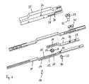
- the FIG. 1 shows an exploded view of a fitting 10.
- the fitting 10 comprises a drive rod 11, which has a toothed rod 13, in particular ladder rack, trained portion and a decoupling portion 14 in a cranked region 12.
- the decoupling section 14 essentially has a slot 15.
- the rack 13 cooperates with a gear formed as a coupling element 16, which is arranged between the drive rod 11 and a fitting part 17, which also has a rack 18, in particular a ladder rack.
- a pin locking element 19 can be fastened.
- the locking element 19 extends through a cuff rail 20 and a sliding member 21 and is connected at its free end 22 at a position 23 to the fitting 17, in particular riveted.
- the drive rod 11, the fitting part 17, the faceplate 20 and the coupling element 16 are at least partially in a housing trained fitting part 25 is arranged.
- the fitting part 25 has recesses 26 in which the coupling element 16 with axial projections 27, which serve as a rotation axis, is mounted.
- the fitting part 25 has a control cam 28, which is designed as a backdrop on.
- a locking means 29 is guided with a bolt 30.
- the locking means 29 extends through the recess 31 of the drive rod 11 and in a certain relative position of drive rod 11 and fitting 17 and the recess 32 of the fitting part 17.
- the locking means 29 both recesses 31, 32 of the drive rod 11 and the fitting 17 penetrates, so they are coupled together. A relative movement, seen in the longitudinal direction of the drive rod 11, is therefore not possible.
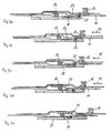
- the operation of the fitting 10 according to the invention is based on the FIGS. 2a to 2e explained.
- the in the FIG. 2a illustrated situation corresponds to a position of the fitting with locked window or door leaf.
- the locking element 29 extends through both the drive rod 11 and the fitting part 17.
- the locking means 29 is located in an outer right position of the control cam 28.
- the coupling element 16 is only with the rack 18 into engagement. With respect to the drive rod 11, it is arranged in Entkoppelabêt 14 and thus does not interact with the drive rod 11.
- the drive rod 11 is moved to the left in the direction of arrow 35, as shown in the FIG. 2b is indicated, the fitting part 17 is taken due to the coupling with the locking element 29 and thus the locking element 19 in the direction of movement of the drive rod.
- the in the FIG. 2a shown situation corresponds to a locking position of the locking element 19.
- the in the Figure 2c shown situation corresponds to a position of the locking element 19, which allows a rotational opening of the wing.
- the FIG. 2e illustrates a situation in which the locking element 19 assumes a position that allows tilt opening of a door or window sash. It can be seen that the locking element 19 always performs a very small stroke and during a part of the movement of the drive rod 11 in the direction of arrow 35 is moved in the same direction and during a part of the movement of the drive rod 11 in the direction of arrow 35 opposite direction is moved.
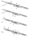
- FIG. 3 shows an exploded view of an alternative embodiment of a fitting 40 according to the invention.
- a drive rod 41 has a rack 42, which is designed as a ladder rack on. This cooperates with a coupling element 43, whose teeth project through a slot 44 of a faceplate 45 in order to come into engagement with the rack 42.
- the coupling element 43 is arranged in a two-part housing with the housing parts 46, 47. In this case, the axial projections 48 of the coupling element 43, which serve as a rotation axis, in the guides 49, 50 of the housing parts 46, 47 are arranged.
- the coupling element 43 also interacts with a locking element 51, which has a rack 52, which is designed as a ladder rack.
- the locking element 51 is likewise guided in the housing 46, 47, in particular in the recess 53.
- the coupling element 43 has a turnstile 60, which can be guided in the orientation shown in the guide 49 and thus allows a displacement of the coupling element 43 in the longitudinal direction of the drive rod 41.
- a rotational movement of the coupling element 43 is only possible when the turnstile 60 is located in the region of the recess 61 at the end of the guide 49.
- the guide 49 has opposite surfaces 62, 63, which cooperate with the surfaces 64 of the turnstile 60.
- the surfaces 64 may slide along the surfaces 62, 63.
Claims (15)
- Ferrure (10, 40) pour une fenêtre, une porte ou similaire pourvue d'un battant pivotant et basculant, avec une tige de crémone (11, 41) qui peut être entraînée dans la direction longitudinale de la tige de crémone (11, 41), et avec un élément de verrouillage (19, 51) qui prend différentes positions en fonction de la position de la tige de crémone (11, 41), sachant que la tige de crémone (11, 41) et l'élément de verrouillage (51) ou une partie de ferrure (17) reliée à l'élément de verrouillage (19) sont, par l'intermédiaire d'un élément de couplage (16, 43), couplés entre eux en déplacement de telle sorte qu'un déplacement de la tige de crémone (11, 41) dans une direction produit un déplacement de l'élément de verrouillage (19, 51) en direction opposée, sachant que sont prévus des moyens de blocage empêchant un déplacement relatif entre la tige de crémone (11, 41) et l'élément de verrouillage (19, 51), de sorte qu'un déplacement de la tige de crémone (11, 41) dans une direction produit un déplacement de l'élément de verrouillage (19, 51) dans la même direction, caractérisée en ce que les moyens de blocage comprennent un élément de blocage (29) pouvant être déplacé transversalement à la direction de déplacement de la tige de crémone (11).
- Ferrure selon la revendication 1, caractérisée en ce que la tige de crémone (11, 41) et l'élément de verrouillage (51) ou une partie de ferrure (17) reliée à l'élément de verrouillage (19) sont respectivement réalisés dans un tronçon sous forme de crémaillère (13, 18, 43, 52), en particulier de crémaillère de Riggenbach, et l'élément de couplage (16, 43) est réalisé sous forme de roue dentée coopérant avec cette crémaillère.
- Ferrure selon la revendication 2, caractérisée en ce que la roue dentée est disposée à rotation sur une partie de ferrure (17, 46, 47), en particulier dans un boîtier.
- Ferrure selon l'une des revendications précédentes, caractérisée en ce qu'un tronçon de découplage (14) est prévu sur la tige de crémone (11), tronçon qui, lors d'un déplacement de la tige de crémone (11) peut être déplacé le long de l'élément de couplage (16) sans que l'élément de couplage (16) coopère avec la tige de crémone (11).
- Ferrure selon l'une des revendications précédentes, caractérisée en ce que les moyens de blocage peuvent être activés, en particulier en fonction de la position relative de la tige de crémone (11,41) et de l'élément de verrouillage (19, 51).
- Ferrure selon l'une des revendications précédentes, caractérisée en ce que l'élément de blocage, dans une première position, traverse à la fois la tige de crémone (11) et l'élément de verrouillage ou une partie de ferrure (17) reliée à l'élément
de verrouillage (19), et définit ainsi leur position relative. - Ferrure selon l'une des revendications précédentes, caractérisée en ce que l'élément de blocage (29) coopère avec une came de commande (28) qui détermine le déplacement de l'élément de blocage (29) transversalement à la direction de déplacement de la tige de crémone (11).
- Ferrure (10, 40) pour une fenêtre, une porte ou similaire pourvue d'un battant pivotant et basculant, avec une tige de crémone (11, 41) qui peut être entraînée dans la direction longitudinale de la tige de crémone (11, 41), et avec un élément de verrouillage (19, 51) qui prend différentes positions en fonction de la position de la tige de crémone (11, 41), sachant que la tige de crémone (11, 41) et l'élément de verrouillage (51) ou une partie de ferrure (17) reliée à l'élément de verrouillage (19) sont, par l'intermédiaire d'un élément de couplage (16, 43), couplés entre eux en déplacement de telle sorte qu'un déplacement de la tige de crémone (11, 41) dans une direction produit un déplacement de l'élément de verrouillage (19, 51) en direction opposée, sachant que sont prévus des moyens de blocage empêchant un déplacement relatif entre la tige de crémone (11, 41) et l'élément de verrouillage (19, 51), de sorte qu'un déplacement de la tige de crémone (11, 41) dans une direction produit un déplacement de l'élément de verrouillage (19, 51) dans la même direction, caractérisée en ce que les moyens de blocage comprennent l'élément de couplage (43) ainsi qu'un moyen de blocage en rotation (60) de l'élément de couplage (43).
- Ferrure selon la revendication 8, caractérisée en ce que la tige de crémone (11, 41) et l'élément de verrouillage (51) ou une partie de ferrure (17) reliée à l'élément de verrouillage (19) sont respectivement réalisés dans un tronçon sous forme de crémaillère (13, 18, 43, 52), en particulier de crémaillère de Riggenbach, et l'élément de couplage (16, 43) est réalisé sous forme de roue dentée coopérant avec cette crémaillère.
- Ferrure selon la revendication 9, caractérisée en ce que la roue dentée est disposée à rotation sur une partie de ferrure (17, 46, 47), en particulier dans un boîtier.
- Ferrure selon l'une des revendications précédentes 8 à 10, caractérisée en ce que les moyens de blocage peuvent être activés, en particulier en fonction de la position relative de la tige de crémone (11, 41) et de l'élément de verrouillage (19, 51).
- Ferrure selon l'une des revendications précédentes 8 à 11, caractérisée en ce que l'élément de couplage (43), dans l'état bloqué en rotation par rapport à une partie de ferrure (46, 47) sur laquelle il est disposé à rotation dans l'état non bloqué en rotation, peut être déplacé le long d'un guide (49, 50) dans la direction de déplacement de la tige de crémone.
- Ferrure selon l'une des revendications 8 à 12, caractérisée en ce que le moyen de blocage en rotation (60) coopère avec un guide (49, 50), en particulier d'un boîtier (46, 47).
- Ferrure selon la revendication 13, caractérisée en ce qu'un évidement (61) pour le moyen de blocage en rotation (60) est prévu dans la région d'une extrémité du guide (49, 50), de sorte que l'élément de couplage (43) est libre de tourner.
- Fenêtre, porte ou similaire avec un battant pivotant et basculant par rapport à un encadrement fixe et avec une ferrure (10, 40) selon l'une des revendications précédentes, sachant que la tige de crémone (11, 41) peut être déplacée dans une direction depuis une position de verrouillage, dans laquelle l'élément de verrouillage (19, 51) coopère avec un élément de fermeture, dans une position permettant une ouverture par pivotement du battant et dans une position permettant une position de basculement du battant, et sachant que l'élément de verrouillage (19, 51) accomplit, pendant une partie du déplacement de la tige de crémone (11, 41), un déplacement en direction opposée.
Priority Applications (2)
| Application Number | Priority Date | Filing Date | Title |
|---|---|---|---|
| EP09175555A EP2320013B1 (fr) | 2009-11-10 | 2009-11-10 | Armature dotée d'une transmission de renvoi |
| PL09175555T PL2320013T3 (pl) | 2009-11-10 | 2009-11-10 | Okucie z nawrotnicą |
Applications Claiming Priority (1)
| Application Number | Priority Date | Filing Date | Title |
|---|---|---|---|
| EP09175555A EP2320013B1 (fr) | 2009-11-10 | 2009-11-10 | Armature dotée d'une transmission de renvoi |
Publications (2)
| Publication Number | Publication Date |
|---|---|
| EP2320013A1 EP2320013A1 (fr) | 2011-05-11 |
| EP2320013B1 true EP2320013B1 (fr) | 2012-08-08 |
Family
ID=42103048
Family Applications (1)
| Application Number | Title | Priority Date | Filing Date |
|---|---|---|---|
| EP09175555A Not-in-force EP2320013B1 (fr) | 2009-11-10 | 2009-11-10 | Armature dotée d'une transmission de renvoi |
Country Status (2)
| Country | Link |
|---|---|
| EP (1) | EP2320013B1 (fr) |
| PL (1) | PL2320013T3 (fr) |
Families Citing this family (1)
| Publication number | Priority date | Publication date | Assignee | Title |
|---|---|---|---|---|
| DE102014204899A1 (de) * | 2014-03-17 | 2015-09-17 | Aug. Winkhaus Gmbh & Co. Kg | Treibriegelbeschlag |
Family Cites Families (3)
| Publication number | Priority date | Publication date | Assignee | Title |
|---|---|---|---|---|
| DE50014923D1 (de) | 1999-06-17 | 2008-03-13 | Hautau Gmbh | Getriebeanordnung für einen Stangenverschluss |
| EP1566509B1 (fr) | 2004-02-19 | 2010-04-14 | Roto Frank Ag | Adapteur pour ferrure et mécanism de fermeture pour une porte, une fenêtre ou similaire |
| DE202008009184U1 (de) | 2008-07-09 | 2009-11-12 | Siegenia-Aubi Kg | Verriegelungsvorrichtung |
-
2009
- 2009-11-10 PL PL09175555T patent/PL2320013T3/pl unknown
- 2009-11-10 EP EP09175555A patent/EP2320013B1/fr not_active Not-in-force
Also Published As
| Publication number | Publication date |
|---|---|
| EP2320013A1 (fr) | 2011-05-11 |
| PL2320013T3 (pl) | 2013-01-31 |
Similar Documents
| Publication | Publication Date | Title |
|---|---|---|
| DE102006059568B4 (de) | Schließanlage für Türen, Fenster oder dergleichen, insbesondere Treibstangenschloss mit Panikfunktion und Mehrpunktverriegelung | |
| EP1932989A2 (fr) | Système de fermeture pour portes, fenêtres ou analogues, en particulier crémone-serrure à fonction d'urgence et de verrouillage à plusieurs points | |
| EP2264268B2 (fr) | Crémone serrure | |
| EP1574644A2 (fr) | Système de verrouillage pour portes, fenêtres ou similaires, notamment crémone-serrure avec fonction anti-panique et avec plusieurs points de condamnation | |
| DE102017129427B3 (de) | Scharnierverschluss | |
| EP2692969B1 (fr) | Engrenage d'un dispositif de verrouillage à crémone, dispositif de verrouillage avec un tel engrenage ainsi que fenêtre, porte ou analogue avec un tel dispositif de verrouillage à crémone | |
| EP1286012B1 (fr) | Ferrure de verrouillage avec un elément de verrou tournante | |
| EP0007395A1 (fr) | Serrure pour portes à serrure cylindrique actionnée par une clé | |
| EP0485767B1 (fr) | Verrouillage pour l'aile, en particulier l'aile coulissante d'une fenêtre, porte etc. | |
| EP3144455B1 (fr) | Dispositif de verrouillage | |
| EP2689083B1 (fr) | Armoire, en particulier armoire pour bouteilles de gaz | |
| EP1739260B1 (fr) | Transmission d'une ferrure pour fenêtre, portes, ou similaire, et procédé pour actionner la transmission | |
| EP2143859B1 (fr) | Système de verouillage | |
| EP1840304A2 (fr) | Verrou à barre rotative, en particulier pour portes pivotantes de superstructures de véhicules | |
| EP3371397B1 (fr) | Ensemble ferrure | |
| EP2320013B1 (fr) | Armature dotée d'une transmission de renvoi | |
| EP1672153B1 (fr) | Serrure avec pêne dormant et dispositif de commande du pêne dormant | |
| EP2453086B1 (fr) | Ferrure de crémone pour battant fixe de fenêtres ou de portes à deux vantaux sans montant médian | |
| DE10322798A1 (de) | Rohrverriegelung | |
| DE102010055397B4 (de) | Verriegelungs-/Entriegelungsvorrichtung für eine Schiebetür und mit einer solchen Vorrichtung ausgestattete Tür | |
| EP0974721B1 (fr) | Serrure à plusieurs pênes | |
| EP0972900B1 (fr) | Crémone-serrure | |
| WO2015176695A1 (fr) | Dispositif de serrure antipanique pour une porte d'issue de secours d'une porte sectionnelle ou d'une porte levante-pliante sectionnelle | |
| DE102004054979B4 (de) | Fenster, Tür oder dergleichen mit einer flächenhaften Verriegelungseinrichtung | |
| EP1533454B1 (fr) | Ferrure à crémone |
Legal Events
| Date | Code | Title | Description |
|---|---|---|---|
| PUAI | Public reference made under article 153(3) epc to a published international application that has entered the european phase |
Free format text: ORIGINAL CODE: 0009012 |
|
| 17P | Request for examination filed |
Effective date: 20101021 |
|
| AK | Designated contracting states |
Kind code of ref document: A1 Designated state(s): AT BE BG CH CY CZ DE DK EE ES FI FR GB GR HR HU IE IS IT LI LT LU LV MC MK MT NL NO PL PT RO SE SI SK SM TR |
|
| AX | Request for extension of the european patent |
Extension state: AL BA RS |
|
| 17Q | First examination report despatched |
Effective date: 20111103 |
|
| GRAP | Despatch of communication of intention to grant a patent |
Free format text: ORIGINAL CODE: EPIDOSNIGR1 |
|
| GRAS | Grant fee paid |
Free format text: ORIGINAL CODE: EPIDOSNIGR3 |
|
| GRAA | (expected) grant |
Free format text: ORIGINAL CODE: 0009210 |
|
| AK | Designated contracting states |
Kind code of ref document: B1 Designated state(s): AT BE BG CH CY CZ DE DK EE ES FI FR GB GR HR HU IE IS IT LI LT LU LV MC MK MT NL NO PL PT RO SE SI SK SM TR |
|
| REG | Reference to a national code |
Ref country code: GB Ref legal event code: FG4D Free format text: NOT ENGLISH |
|
| REG | Reference to a national code |
Ref country code: AT Ref legal event code: REF Ref document number: 569889 Country of ref document: AT Kind code of ref document: T Effective date: 20120815 Ref country code: CH Ref legal event code: EP |
|
| REG | Reference to a national code |
Ref country code: IE Ref legal event code: FG4D Free format text: LANGUAGE OF EP DOCUMENT: GERMAN |
|
| REG | Reference to a national code |
Ref country code: DE Ref legal event code: R096 Ref document number: 502009004310 Country of ref document: DE Effective date: 20121004 |
|
| REG | Reference to a national code |
Ref country code: NL Ref legal event code: VDEP Effective date: 20120808 |
|
| REG | Reference to a national code |
Ref country code: LT Ref legal event code: MG4D Effective date: 20120808 |
|
| PG25 | Lapsed in a contracting state [announced via postgrant information from national office to epo] |
Ref country code: HR Free format text: LAPSE BECAUSE OF FAILURE TO SUBMIT A TRANSLATION OF THE DESCRIPTION OR TO PAY THE FEE WITHIN THE PRESCRIBED TIME-LIMIT Effective date: 20120808 Ref country code: IS Free format text: LAPSE BECAUSE OF FAILURE TO SUBMIT A TRANSLATION OF THE DESCRIPTION OR TO PAY THE FEE WITHIN THE PRESCRIBED TIME-LIMIT Effective date: 20121208 Ref country code: CY Free format text: LAPSE BECAUSE OF FAILURE TO SUBMIT A TRANSLATION OF THE DESCRIPTION OR TO PAY THE FEE WITHIN THE PRESCRIBED TIME-LIMIT Effective date: 20120808 Ref country code: NO Free format text: LAPSE BECAUSE OF FAILURE TO SUBMIT A TRANSLATION OF THE DESCRIPTION OR TO PAY THE FEE WITHIN THE PRESCRIBED TIME-LIMIT Effective date: 20121108 Ref country code: FI Free format text: LAPSE BECAUSE OF FAILURE TO SUBMIT A TRANSLATION OF THE DESCRIPTION OR TO PAY THE FEE WITHIN THE PRESCRIBED TIME-LIMIT Effective date: 20120808 Ref country code: LT Free format text: LAPSE BECAUSE OF FAILURE TO SUBMIT A TRANSLATION OF THE DESCRIPTION OR TO PAY THE FEE WITHIN THE PRESCRIBED TIME-LIMIT Effective date: 20120808 |
|
| REG | Reference to a national code |
Ref country code: PL Ref legal event code: T3 |
|
| PG25 | Lapsed in a contracting state [announced via postgrant information from national office to epo] |
Ref country code: SE Free format text: LAPSE BECAUSE OF FAILURE TO SUBMIT A TRANSLATION OF THE DESCRIPTION OR TO PAY THE FEE WITHIN THE PRESCRIBED TIME-LIMIT Effective date: 20120808 Ref country code: GR Free format text: LAPSE BECAUSE OF FAILURE TO SUBMIT A TRANSLATION OF THE DESCRIPTION OR TO PAY THE FEE WITHIN THE PRESCRIBED TIME-LIMIT Effective date: 20121109 Ref country code: LV Free format text: LAPSE BECAUSE OF FAILURE TO SUBMIT A TRANSLATION OF THE DESCRIPTION OR TO PAY THE FEE WITHIN THE PRESCRIBED TIME-LIMIT Effective date: 20120808 Ref country code: PT Free format text: LAPSE BECAUSE OF FAILURE TO SUBMIT A TRANSLATION OF THE DESCRIPTION OR TO PAY THE FEE WITHIN THE PRESCRIBED TIME-LIMIT Effective date: 20121210 Ref country code: SI Free format text: LAPSE BECAUSE OF FAILURE TO SUBMIT A TRANSLATION OF THE DESCRIPTION OR TO PAY THE FEE WITHIN THE PRESCRIBED TIME-LIMIT Effective date: 20120808 |
|
| PG25 | Lapsed in a contracting state [announced via postgrant information from national office to epo] |
Ref country code: NL Free format text: LAPSE BECAUSE OF FAILURE TO SUBMIT A TRANSLATION OF THE DESCRIPTION OR TO PAY THE FEE WITHIN THE PRESCRIBED TIME-LIMIT Effective date: 20120808 |
|
| PG25 | Lapsed in a contracting state [announced via postgrant information from national office to epo] |
Ref country code: EE Free format text: LAPSE BECAUSE OF FAILURE TO SUBMIT A TRANSLATION OF THE DESCRIPTION OR TO PAY THE FEE WITHIN THE PRESCRIBED TIME-LIMIT Effective date: 20120808 Ref country code: DK Free format text: LAPSE BECAUSE OF FAILURE TO SUBMIT A TRANSLATION OF THE DESCRIPTION OR TO PAY THE FEE WITHIN THE PRESCRIBED TIME-LIMIT Effective date: 20120808 Ref country code: ES Free format text: LAPSE BECAUSE OF FAILURE TO SUBMIT A TRANSLATION OF THE DESCRIPTION OR TO PAY THE FEE WITHIN THE PRESCRIBED TIME-LIMIT Effective date: 20121119 Ref country code: RO Free format text: LAPSE BECAUSE OF FAILURE TO SUBMIT A TRANSLATION OF THE DESCRIPTION OR TO PAY THE FEE WITHIN THE PRESCRIBED TIME-LIMIT Effective date: 20120808 |
|
| BERE | Be: lapsed |
Owner name: ROTO FRANK A.G. Effective date: 20121130 |
|
| PG25 | Lapsed in a contracting state [announced via postgrant information from national office to epo] |
Ref country code: SK Free format text: LAPSE BECAUSE OF FAILURE TO SUBMIT A TRANSLATION OF THE DESCRIPTION OR TO PAY THE FEE WITHIN THE PRESCRIBED TIME-LIMIT Effective date: 20120808 Ref country code: IT Free format text: LAPSE BECAUSE OF FAILURE TO SUBMIT A TRANSLATION OF THE DESCRIPTION OR TO PAY THE FEE WITHIN THE PRESCRIBED TIME-LIMIT Effective date: 20120808 |
|
| PLBE | No opposition filed within time limit |
Free format text: ORIGINAL CODE: 0009261 |
|
| STAA | Information on the status of an ep patent application or granted ep patent |
Free format text: STATUS: NO OPPOSITION FILED WITHIN TIME LIMIT |
|
| 26N | No opposition filed |
Effective date: 20130510 |
|
| PG25 | Lapsed in a contracting state [announced via postgrant information from national office to epo] |
Ref country code: BG Free format text: LAPSE BECAUSE OF FAILURE TO SUBMIT A TRANSLATION OF THE DESCRIPTION OR TO PAY THE FEE WITHIN THE PRESCRIBED TIME-LIMIT Effective date: 20121108 |
|
| REG | Reference to a national code |
Ref country code: IE Ref legal event code: MM4A |
|
| PG25 | Lapsed in a contracting state [announced via postgrant information from national office to epo] |
Ref country code: BE Free format text: LAPSE BECAUSE OF NON-PAYMENT OF DUE FEES Effective date: 20121130 |
|
| REG | Reference to a national code |
Ref country code: DE Ref legal event code: R097 Ref document number: 502009004310 Country of ref document: DE Effective date: 20130510 |
|
| PG25 | Lapsed in a contracting state [announced via postgrant information from national office to epo] |
Ref country code: IE Free format text: LAPSE BECAUSE OF NON-PAYMENT OF DUE FEES Effective date: 20121110 |
|
| PG25 | Lapsed in a contracting state [announced via postgrant information from national office to epo] |
Ref country code: MT Free format text: LAPSE BECAUSE OF FAILURE TO SUBMIT A TRANSLATION OF THE DESCRIPTION OR TO PAY THE FEE WITHIN THE PRESCRIBED TIME-LIMIT Effective date: 20120808 |
|
| PG25 | Lapsed in a contracting state [announced via postgrant information from national office to epo] |
Ref country code: MC Free format text: LAPSE BECAUSE OF NON-PAYMENT OF DUE FEES Effective date: 20121130 |
|
| PG25 | Lapsed in a contracting state [announced via postgrant information from national office to epo] |
Ref country code: SM Free format text: LAPSE BECAUSE OF FAILURE TO SUBMIT A TRANSLATION OF THE DESCRIPTION OR TO PAY THE FEE WITHIN THE PRESCRIBED TIME-LIMIT Effective date: 20120808 Ref country code: LU Free format text: LAPSE BECAUSE OF NON-PAYMENT OF DUE FEES Effective date: 20121110 |
|
| GBPC | Gb: european patent ceased through non-payment of renewal fee |
Effective date: 20131110 |
|
| PG25 | Lapsed in a contracting state [announced via postgrant information from national office to epo] |
Ref country code: HU Free format text: LAPSE BECAUSE OF FAILURE TO SUBMIT A TRANSLATION OF THE DESCRIPTION OR TO PAY THE FEE WITHIN THE PRESCRIBED TIME-LIMIT Effective date: 20091110 |
|
| PG25 | Lapsed in a contracting state [announced via postgrant information from national office to epo] |
Ref country code: GB Free format text: LAPSE BECAUSE OF NON-PAYMENT OF DUE FEES Effective date: 20131110 |
|
| PGFP | Annual fee paid to national office [announced via postgrant information from national office to epo] |
Ref country code: CZ Payment date: 20141029 Year of fee payment: 6 Ref country code: CH Payment date: 20141120 Year of fee payment: 6 |
|
| PGFP | Annual fee paid to national office [announced via postgrant information from national office to epo] |
Ref country code: AT Payment date: 20141119 Year of fee payment: 6 Ref country code: FR Payment date: 20141118 Year of fee payment: 6 Ref country code: PL Payment date: 20141014 Year of fee payment: 6 |
|
| PG25 | Lapsed in a contracting state [announced via postgrant information from national office to epo] |
Ref country code: MK Free format text: LAPSE BECAUSE OF FAILURE TO SUBMIT A TRANSLATION OF THE DESCRIPTION OR TO PAY THE FEE WITHIN THE PRESCRIBED TIME-LIMIT Effective date: 20120808 |
|
| REG | Reference to a national code |
Ref country code: CH Ref legal event code: PL |
|
| REG | Reference to a national code |
Ref country code: AT Ref legal event code: MM01 Ref document number: 569889 Country of ref document: AT Kind code of ref document: T Effective date: 20151110 |
|
| PG25 | Lapsed in a contracting state [announced via postgrant information from national office to epo] |
Ref country code: CZ Free format text: LAPSE BECAUSE OF NON-PAYMENT OF DUE FEES Effective date: 20151110 Ref country code: LI Free format text: LAPSE BECAUSE OF NON-PAYMENT OF DUE FEES Effective date: 20151130 Ref country code: CH Free format text: LAPSE BECAUSE OF NON-PAYMENT OF DUE FEES Effective date: 20151130 |
|
| REG | Reference to a national code |
Ref country code: FR Ref legal event code: ST Effective date: 20160729 |
|
| PG25 | Lapsed in a contracting state [announced via postgrant information from national office to epo] |
Ref country code: AT Free format text: LAPSE BECAUSE OF NON-PAYMENT OF DUE FEES Effective date: 20151110 |
|
| PG25 | Lapsed in a contracting state [announced via postgrant information from national office to epo] |
Ref country code: FR Free format text: LAPSE BECAUSE OF NON-PAYMENT OF DUE FEES Effective date: 20151130 |
|
| PG25 | Lapsed in a contracting state [announced via postgrant information from national office to epo] |
Ref country code: PL Free format text: LAPSE BECAUSE OF NON-PAYMENT OF DUE FEES Effective date: 20151110 |
|
| PGFP | Annual fee paid to national office [announced via postgrant information from national office to epo] |
Ref country code: TR Payment date: 20171109 Year of fee payment: 9 |
|
| PGFP | Annual fee paid to national office [announced via postgrant information from national office to epo] |
Ref country code: DE Payment date: 20181129 Year of fee payment: 10 |
|
| REG | Reference to a national code |
Ref country code: DE Ref legal event code: R119 Ref document number: 502009004310 Country of ref document: DE |
|
| PG25 | Lapsed in a contracting state [announced via postgrant information from national office to epo] |
Ref country code: DE Free format text: LAPSE BECAUSE OF NON-PAYMENT OF DUE FEES Effective date: 20200603 |
|
| PG25 | Lapsed in a contracting state [announced via postgrant information from national office to epo] |
Ref country code: TR Free format text: LAPSE BECAUSE OF NON-PAYMENT OF DUE FEES Effective date: 20181110 |