EP2264268B2 - Drive bar lock - Google Patents
Drive bar lock Download PDFInfo
- Publication number
- EP2264268B2 EP2264268B2 EP10159286.3A EP10159286A EP2264268B2 EP 2264268 B2 EP2264268 B2 EP 2264268B2 EP 10159286 A EP10159286 A EP 10159286A EP 2264268 B2 EP2264268 B2 EP 2264268B2
- Authority
- EP
- European Patent Office
- Prior art keywords
- ejector
- drive
- control slide
- slide
- lock
- Prior art date
- Legal status (The legal status is an assumption and is not a legal conclusion. Google has not performed a legal analysis and makes no representation as to the accuracy of the status listed.)
- Active
Links
Images


Classifications
-
- E—FIXED CONSTRUCTIONS
- E05—LOCKS; KEYS; WINDOW OR DOOR FITTINGS; SAFES
- E05B—LOCKS; ACCESSORIES THEREFOR; HANDCUFFS
- E05B63/00—Locks or fastenings with special structural characteristics
- E05B63/24—Arrangements in which the fastening members which engage one another are mounted respectively on the wing and the frame and are both movable, e.g. for release by moving either of them
-
- E—FIXED CONSTRUCTIONS
- E05—LOCKS; KEYS; WINDOW OR DOOR FITTINGS; SAFES
- E05C—BOLTS OR FASTENING DEVICES FOR WINGS, SPECIALLY FOR DOORS OR WINDOWS
- E05C7/00—Fastening devices specially adapted for two wings
- E05C7/04—Fastening devices specially adapted for two wings for wings which abut when closed
-
- E—FIXED CONSTRUCTIONS
- E05—LOCKS; KEYS; WINDOW OR DOOR FITTINGS; SAFES
- E05B—LOCKS; ACCESSORIES THEREFOR; HANDCUFFS
- E05B47/00—Operating or controlling locks or other fastening devices by electric or magnetic means
- E05B47/0001—Operating or controlling locks or other fastening devices by electric or magnetic means with electric actuators; Constructional features thereof
- E05B2047/0014—Constructional features of actuators or power transmissions therefor
- E05B2047/0015—Output elements of actuators
- E05B2047/0016—Output elements of actuators with linearly reciprocating motion
-
- E—FIXED CONSTRUCTIONS
- E05—LOCKS; KEYS; WINDOW OR DOOR FITTINGS; SAFES
- E05B—LOCKS; ACCESSORIES THEREFOR; HANDCUFFS
- E05B47/00—Operating or controlling locks or other fastening devices by electric or magnetic means
- E05B47/0001—Operating or controlling locks or other fastening devices by electric or magnetic means with electric actuators; Constructional features thereof
- E05B47/0012—Operating or controlling locks or other fastening devices by electric or magnetic means with electric actuators; Constructional features thereof with rotary electromotors
-
- E—FIXED CONSTRUCTIONS
- E05—LOCKS; KEYS; WINDOW OR DOOR FITTINGS; SAFES
- E05B—LOCKS; ACCESSORIES THEREFOR; HANDCUFFS
- E05B65/00—Locks or fastenings for special use
- E05B65/10—Locks or fastenings for special use for panic or emergency doors
-
- E—FIXED CONSTRUCTIONS
- E05—LOCKS; KEYS; WINDOW OR DOOR FITTINGS; SAFES
- E05C—BOLTS OR FASTENING DEVICES FOR WINGS, SPECIALLY FOR DOORS OR WINDOWS
- E05C9/00—Arrangements of simultaneously actuated bolts or other securing devices at well-separated positions on the same wing
- E05C9/04—Arrangements of simultaneously actuated bolts or other securing devices at well-separated positions on the same wing with two sliding bars moved in opposite directions when fastening or unfastening
- E05C9/041—Arrangements of simultaneously actuated bolts or other securing devices at well-separated positions on the same wing with two sliding bars moved in opposite directions when fastening or unfastening with rack and pinion mechanism
Definitions
- the invention relates to a drive bolt lock for a door having an active leaf, with a latch ejector, a control slide that can be displaced parallel to a faceplate, a latch ejector drive driven by the control slide, and a retraction slide for a drive rod.
- active leaf and inactive leaf locking systems are usually used. So-called espagnolette locks are used on the passive leaf side.
- the passive leaf lock When the passive leaf lock is actuated in a panic, the upper and lower driving bar rods are retracted and at the same time the latch and the bolt of the active leaf lock are pushed back into the lock case via the release slide so that the door system can be opened.
- the EP-A-1 947 273 shows such a shoot bolt lock which, when actuated, simultaneously pushes out the latch and pulls in the upper and lower drive rods. With this lock, only the complete passive leaf can be released. It is not possible that only the active leaf is released via the espagnolette lock, whereas the passive leaf remains locked via the espagnolette.
- the invention is based on the object of providing a shoot bolt lock which can be actuated electrically and with which either only the active leaf or both leaves can be released, depending on the requirements.
- a coupling element is advantageously provided which, when the control slide is actuated, drives the draw-in slide with a time delay.
- the latch of the active leaf lock is first pushed out of the shooting bolt lock so that the inactive leaf remains locked via the connecting rod or the connecting rods.
- the drive rods are then unlocked in a second work step so that the inactive leaf is completely unlocked. It can now also be opened. According to the invention, this is achieved in that the extension of the latch and the retraction of the drive rods take place one after the other.
- the espagnolette lock according to the invention can not only be operated manually by means of a handle but can also be controlled by a motor.
- the sequential motor-driven shoot bolt lock thus divides the overall sequence of movements when the lock is actuated into two sequences of movements running one behind the other.
- the latch and, if necessary, a bolt of the active leaf lock are pushed out via the ejector (s) during the first movement, which is necessary e.g. for the use of access control systems or the automated opening of the active leaf.
- the espagnolette rods are drawn in, which is necessary for the additional release of the inactive leaf.
- the electric opener can be saved with the invention and both the upper and lower drive bar rods can be used.
- control slide has an idle position opposite the coupling member and an adjoining driver section.
- a bolt ejector and a bolt ejector drive driven by the control slide are preferably also provided. This means that a locked active leaf lock can also be unlocked by sliding the bolt out of the espagnolette lock.
- the shooting bolt lock provides a handle follower and a follower pivot lever which is driven directly or via a transmission gear and which drives the control slide or the latch ejector drive.
- the espagnolette lock can be operated manually not only by actuating the control slide but also by means of a lever handle. By depressing the handle more or less far, only the latch is pushed out or the entire espagnolette lock is unlocked and the inactive leaf can be swiveled open.
- the nut pivot lever is from a gear section is formed or has at least one gear portion.
- the trigger movement can directly drive the latch ejector drive or the movement can be translated by means of a gear so that even small trigger movements are sufficient to extend the latch.
- the control slide In order to block the control slide in the rest position of the shoot bolt lock and thereby lock the drive rods in their extended position, the control slide has an edge recess into which a locking bolt of the latch ejector and / or the bolt ejector engages when the latch ejector and / or the The bolt ejector assumes its pushed-in position.
- the latch ejector drive has a control cam and a guide pin guided in the control cam.
- the control cam is provided in the control slide or in the ejector drive and the guide pin is arranged on the control slide or on the ejector drive.
- an exemplary embodiment of the espagnolette lock provides that the coupling member has a gearwheel which meshes with the draw-in slide and which is driven by a toothed rack section of the control slide.
- the toothed rack section of the control slide is at a distance from the gearwheel when idling, so that it is not actuated.
- the driver section adjoining the idle is formed by the rack section.
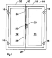
- a door designated as a whole with 10 which has an inactive leaf 12 and an active leaf 14. Both the inactive leaf 12 and the active leaf 14 are pivotably connected to a frame 18 via hinges 16.
- the active leaf 14 can be locked to the active leaf 12 via a lock 20 and the inactive leaf 12 has a espagnolette lock 22 to which an upper drive rod 24 and a lower drive rod 26 are coupled.
- the lower drive rod 26 engages with its downwardly facing free end 28 in the ground and the upper drive rod 24 engages with its upwardly facing free end 30 in the crossbeam 32 of the frame 18.
- the lock 20 and the espagnolette lock 22 are opposite one another, so that the latch of the lock 20 engages in the espagnolette lock 22.
- the bolt of the lock 20 also engages in the shoot bolt lock 22.
- the Figure 2 shows the espagnolette lock 22 without the housing cover, the espagnolette lock 22 being screwed to a cuff 34.
- a control slide 36 which has a shoulder 38 protruding from the lower end of the housing of the espagnolette lock 22.
- a drive motor for example, via which the control slide 36 is displaced vertically, that is to say in the longitudinal direction of the espagnolette lock 22 or parallel to the cuff 34 and in the direction of the arrow 92, can act on this projection 38.
- the control slide 36 has a driver section 40 in the form of a rack section 42.
- a latch ejector drive 44 can also be seen, which is pivotably mounted in the shoot bolt lock 22 via a pivot bearing 46.
- a bolt ejector drive 48 is provided, which is also pivotably mounted via a pivot bearing 50.
- the two ejector drives 44 and 48 are essentially double-armed, with a pin being arranged on each arm 52, 54, which engages in a horizontal elongated hole 56, 58 in the control slide 36.
- the other arm 60, 62 is each configured like a link and rests on a roller 64, 66 of a latch ejector 68 or a bolt ejector 70.
- the roller 64 is located on a shoulder 72 and the roller 66 is located in a recess 74 of the control slide 36. In this position of the latch ejector 68 or of the bolt ejector 70, the control slide 36 is blocked against displacement in the direction of the arrow 92.
- the latch ejector drive 44 is provided with a toothed ring section 76 which extends between the two arms 52 and 60.
- a gearwheel portion 78 of a nut pivot lever 80 which is rotatably connected to a follower 82, meshes with this gear rim portion 76.
- the handle follower 82 takes in the Figure 2 their basic position, in which a pusher 84, only hinted at, protrudes horizontally.
- FIG 3 is that in the Figure 2
- the shooting bolt lock 22 shown is shown in which the handle 84 is pivoted downwards by about 15 ° so that it assumes an intermediate position.
- the nut pivot lever 80 in particular its gear section 78, meshes with the ring gear section 76 of the latch ejector drive 44, the upper arm 60 sliding along the roller 64 and thereby displacing the latch ejector 68 in the direction of the cuff 34.
- the latch ejector 68 assumes its almost completely displaced position in which it has completely pushed a latch engaging in the espagnolette lock 22 out of the espagnolette lock 22.
- the displacement movements of the latch ejector 68 and the bolt ejector 70 are also caused by the fact that the extension 38 is moved in the direction of the arrow 92, for example by means of a motor drive.
- the pusher 84 is pivoted by approx. 30 ° from the horizontal into its end position, whereby the nut pivot lever 80 and with it the gear wheel section 78 is also pivoted further than in the position according to FIG Figure 3 .
- the toothed ring section 76 meshing with the gear section 78 is also pivoted further, as a result of which the latch ejector drive 44 is rotated further clockwise and the latch ejector 68 is thereby pushed slightly further out of the housing of the shoot bolt lock 22.
- This is achieved in that the roller 64 is moved slightly further in the direction of the cuff 34 via the second arm 60.
- the second arm 60 holds the roller 64 in position.
- the control slide 36 is displaced further in the direction of the gear 90 or in the direction of the arrow 92, so that the rack section 42 now meshes with the gear 90.
- a retraction slide 94 Via the gear 90, which is now driven, a retraction slide 94, the rack 96 of which, with respect to the gear 90, is opposite the rack section 42, is drawn into the housing of the espagnolette lock 22.
- the upper drive rod 24 is fastened to the draw-in slide 94, so that it is displaced in the direction of the drive bolt lock 22 and released by the transverse bar 32.
- Moving the control slide 36 in the direction of the arrow 92 also causes the pin 88 to be entrained via the elongated hole 58, so that the bolt ejector drive 48 is also rotated further in the clockwise direction.
- gear wheel 90 and the rack drive 42 form a coupling member 104 which has an idle mode in which a movement of the rack section 42 does not cause any movement of the gear wheel 90 (movement of the control slide from the position shown in FIG Figure 2 position shown in the Figure 3 shown intermediate position).
- the gear 90 is driven.
- the nose 102 and the bending tab 100 represent a coupling member 106, with a movement of the control slide 36 from the one shown in FIG Figure 2 position shown in the Figure 3
- the intermediate position shown in which the bending tab 100 is only moved within the recess 101, does not cause any displacement of the draw-in slide 98.
- the illustrated end position of the control slide 36 takes the bending tab 100 with it, the nose 102 and thus the draw-in slide 98. In this way, the lower drive rod 26 is moved in the direction of arrow 92 and pulled out of the ground, since the drive rod 26 is fastened to the draw-in slide 98.
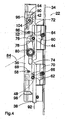
- the Figures 6 to 9 show a second exemplary embodiment in which the control slide 36 can also be driven by a motor via the extension 38 in the direction of the arrow 92.
- the control slide 36 In its lower region, the control slide 36 has a control cam 108 with an inclined section 110 and a section 112 oriented parallel to the direction of displacement of the control slide 36 according to arrow 92.
- a pin 114 which protrudes from the bolt ejector 70, is guided in this control cam 108.
- a pin 116 protrudes therefrom, which engages in a control cam 118 which is provided in the latch ejector 68.
- the control cam 118 also has an inclined section 120 and a section 122 oriented parallel to the direction of displacement of the control slide 36 according to arrow 92. Both the latch ejector 68 and the bolt ejector 70 are guided via horizontally arranged guide elements 124 in such a way that they can only be moved in the direction of the faceplate 34.
- the pivoting lever 80 of the follower 82 carries on its free, pivotable end a gear 128 which meshes with an internal tooth segment 130 fixed in place in the espagnolette lock 22.
- a toothed ring 126 engages in the toothed wheel 128 and is connected to a control lever 132 which can be pivoted about the axis of the handle follower 82.
- This control lever 132 is in the Figure 7 almost completely covered by the nut pivot lever 80, in the Figure 8 however, shown fully visible, since it has been pivoted through a larger pivot angle.
- At the free end of the control lever 132 there is a control pin 134 which engages in a horizontal groove 136 of the control slide 36.
- the nut pivot lever 80, the gear wheel 128, the internal tooth segment 130, the ring gear 126 and the control lever 132 form a transmission gear 138 with which the rotary movement of the nut 82 is translated to a larger, for example twice or three times the angle of rotation for the control lever 132.
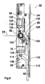
- control slide 36 is instead of the trigger 84 by a motor by means of slide 36 in the direction of arrow 92 in the Figure 7
- the pin 114 is displaced by the inclined section 110 in the control cam 108, and as a result the bolt ejector 70 is displaced in the direction of the faceplate 34.
- the pin 116 is displaced in the inclined section 120 of the control cam 118, as a result of which the latch ejector 68 is also displaced in the direction of the faceplate 34.
- the control pin 134 is carried along via the groove 136 in the control slide 36 which is displaced in the direction of the arrow 92, as a result of which the control lever 132 is pivoted counterclockwise.
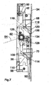
- the Figure 8 shows the control slide 36 in the completely shifted position in the direction of arrow 92, in which the latch ejector 68 and the bolt ejector 70 are still pushed out, since the pin 114 along the vertical section 112 of the control cam 108 and the pin 116 along the vertical Section 122 of the control cam 118 are displaced, and thereby no additional displacement is effected.
- the rack section 42 drives the gear 90, as a result of which the rack 96 of the draw-in slide 94 is displaced against the direction of the arrow 92 and the draw-in slide 94 is drawn in.
- a drive rod 24 attached to the draw-in slide 94 is thus also drawn in.
- the control slide 36 is also displaced when, by means of a pusher 84, the pusher follower 82 is moved from the rest position according to FIG Figure 6 in the intermediate layer according to Figure 7 and from there to the end position according to Figure 8 , in which the inactive leaf 12 can be opened, is rotated.
Description
Die Erfindung betrifft ein Treibriegelschloss für eine einen Gangflügel aufweisende Tür, mit einem Fallenauswerfer, einem parallel zu einer Stulp verschiebbaren Steuerschieber, einem vom Steuerschieber angetriebenen Fallenauswerferantrieb, und einem Einzugsschieber für eine Treibstange.The invention relates to a drive bolt lock for a door having an active leaf, with a latch ejector, a control slide that can be displaced parallel to a faceplate, a latch ejector drive driven by the control slide, and a retraction slide for a drive rod.
Bei einer bevorzugten Fluchttürlösung für zweiflügelige Türen kommen üblicherweise Gangflügel- und Standflügelverschlusssysteme zum Einsatz. Auf der Standflügelseite werden sogenannte Treibriegelschlösser verwendet. Bei einer Panikbetätigung des Standflügelschlosses werden die obere und die untere Treibriegelstange eingezogen und gleichzeitig werden über Auslöseschieber die Falle und der Riegel des Gangflügelschlosses in den Schlosskasten zurückgedrückt, so dass das Türsystem geöffnet werden kann.In a preferred escape door solution for double-leaf doors, active leaf and inactive leaf locking systems are usually used. So-called espagnolette locks are used on the passive leaf side. When the passive leaf lock is actuated in a panic, the upper and lower driving bar rods are retracted and at the same time the latch and the bolt of the active leaf lock are pushed back into the lock case via the release slide so that the door system can be opened.
Die
Soll nun ein zweiflügeliges Türsystem durch den Einsatz von Drehflügelantrieben automatisiert werden, müssen auch die Verschlusskomponenten elektrisch oder motorisch freigegeben werden. Dies geschieht heute mittels eines im Treibriegelschloss integrierten elektrischen Türöffners für die Freigabe der Falle des Gangflügelschlosses und eines in der Zarge eingebauten Türöffners für die Freigabe der oberen Treibriegelstange. Auf die untere Treibriegelstange muss verzichtet werden, da das Schloss nicht mechanisch, also über eine Handhabe betätigt wird und somit die Stangen keine Hubbewegung ausführen würden.If a double-leaf door system is now to be automated using swing leaf drives, the locking components must also be released electrically or by motor. Today this is done by means of an electric door opener integrated in the shoot bolt lock to release the latch of the active leaf lock and a door opener built into the frame to release the upper shoot bolt rod. The lower drive bar rod has to be dispensed with, since the lock is not operated mechanically, i.e. via a handle, and the rods would therefore not perform any lifting movement.
Diese Art der Konstruktion zwingt den Verwender mindestens zwei kostenintensive, für Feuerschutztüren geeignete elektrische Türöffner einzusetzen. Weiterhin schwächt die fehlende untere Treibriegelstange die Eigenschaften der Tür bezüglich ihrer ursprünglichen Eigenschaften in Bezug auf Feuerschutz, Rauchschutz und Einbruchhemmung.This type of construction forces the user to use at least two expensive electric door openers suitable for fire doors. Furthermore, the lack of a lower driving bolt rod weakens the properties of the door with regard to its original properties in terms of fire protection, smoke protection and burglar resistance.
Der Erfindung liegt die Aufgabe zugrunde, ein Treibriegelschloss bereit zu stellen, das elektrisch betätigbar ist und mit dem je nach Anforderung entweder nur der Gangflügel oder beide Flügel freigegeben werden können.The invention is based on the object of providing a shoot bolt lock which can be actuated electrically and with which either only the active leaf or both leaves can be released, depending on the requirements.
Diese Aufgabe wird mit einem Treibriegelschloss gemäß Anspruch 1 gelöst. Vorteilhaft ist ein Kopplungsglied vorgesehen, welches beim Betätigen des Steuerschiebers zeitlich verzögert den Einzugschieber antreibt.This object is achieved with a shoot bolt lock according to
Bei dem erfindungsgemäßen Treibriegelschloss wird aufgrund der zeitlichen Verzögerung des zweiten Bewegungsablaufes, d.h. der Entriegelung der Treibstange, zuerst die Falle des Gangflügelschlosses aus dem Treibriegelschloss ausgeschoben , so dass der Standflügel nach wie vor über die Treibstange oder die Treibstangen verriegelt bleibt. Sodann erfolgt in einem zweiten Arbeitsschritt die Entriegelung der Treibstangen, so dass der Standflügel vollständig entriegelt ist. Er kann nunmehr ebenfalls geöffnet werden. Dies wird erfindungsgemäß dadurch erzielt, dass der Ausschub der Falle und der Einzug der Treibstangen zeitlich nacheinander erfolgen. Außerdem kann das erfindungsgemäße Treibriegelschloss nicht nur mittels eines Drückers manuell betätigt sondern auch motorisch angesteuert werden.In the case of the shooting bolt lock according to the invention, due to the time delay of the second sequence of movements, i.e. the unlocking of the connecting rod, the latch of the active leaf lock is first pushed out of the shooting bolt lock so that the inactive leaf remains locked via the connecting rod or the connecting rods. The drive rods are then unlocked in a second work step so that the inactive leaf is completely unlocked. It can now also be opened. According to the invention, this is achieved in that the extension of the latch and the retraction of the drive rods take place one after the other. In addition, the espagnolette lock according to the invention can not only be operated manually by means of a handle but can also be controlled by a motor.
Das sequentielle motorisch angetriebene Treibriegelschloss teilt also den Gesamtbewegungsablauf beim Betätigen des Schlosses in zwei hintereinander ablaufende Bewegungsabläufe auf. Die Falle und gegebenenfalls ein Riegel des Gangflügelschlosses werden beim ersten Bewegungsablauf über den bzw. die Auswerfer ausgeschoben, was z.B. für die Verwendung von Zutrittskontrollsystemen oder die automatisierte Öffnung des Gangflügels erforderlich ist. Danach erfolgt mittels des zweiten Bewegungsablaufes das Einziehen der Treibriegelstangen, was für die zusätzliche Freigabe des Standflügels erforderlich ist.The sequential motor-driven shoot bolt lock thus divides the overall sequence of movements when the lock is actuated into two sequences of movements running one behind the other. The latch and, if necessary, a bolt of the active leaf lock are pushed out via the ejector (s) during the first movement, which is necessary e.g. for the use of access control systems or the automated opening of the active leaf. Then, by means of the second sequence of movements, the espagnolette rods are drawn in, which is necessary for the additional release of the inactive leaf.
Im Gegensatz zu den oben erwähnten herkömmlichen Konstruktionen können bei der Erfindung die Elektroöffner eingespart und sowohl die obere als auch die untere Treibriegelstange verwendet werden.In contrast to the above-mentioned conventional constructions, the electric opener can be saved with the invention and both the upper and lower drive bar rods can be used.
Bei einer Weiterbildung des erfindungsgemäßen Treibriegelschlosses weist der Steuerschieber gegenüber dem Kopplungsglied einen Leerlauf und einen sich daran anschließenden Mitnehmerabschnitt aufweist. Auf diese Weise kann der oben beschriebene Bewegungsablauf einfach in zwei Bewegungsabschnitte unterteilt werden, wobei im Leerlauf lediglich die Auswerfer betätigt werden, die Treibstangen jedoch in Ruhe verbleiben.In a further development of the espagnolette lock according to the invention, the control slide has an idle position opposite the coupling member and an adjoining driver section. In this way, the sequence of movements described above can be easily divided into two movement sections, with only the ejectors being actuated when idling, but the drive rods remaining at rest.
Wie bereits erwähnt, ist vorzugsweise zusätzlich ein Riegelauswerfer und ein vom Steuerschieber angetriebener Riegelauswerferantrieb vorgesehen. Dadurch kann auch ein verriegeltes Gangflügelschloss entriegelt werden, indem der Riegel aus dem Treibriegelschloss ausgeschoben wird.As already mentioned, a bolt ejector and a bolt ejector drive driven by the control slide are preferably also provided. This means that a locked active leaf lock can also be unlocked by sliding the bolt out of the espagnolette lock.
Eine Weiterbildung des Treibriegelschlosses sieht eine Drückernuss und einen direkt oder über ein Übersetzungsgetriebe angetriebenen Nussschwenkhebel vor, der den Steuerschieber oder den Fallenauswerferantrieb antreibt. Das Treibriegelschloss kann bei dieser Ausgestaltung nicht nur über eine Betätigung des Steuerschiebers sondern auch über einen Drücker manuell betätigt werden. Durch mehr oder weniger weites Niederdrücken des Drückers wird nur die Falle ausgeschoben oder es wird das gesamte Treibriegelschloss entriegelt und der Standflügel kann aufgeschwenkt werden.A further development of the shooting bolt lock provides a handle follower and a follower pivot lever which is driven directly or via a transmission gear and which drives the control slide or the latch ejector drive. In this embodiment, the espagnolette lock can be operated manually not only by actuating the control slide but also by means of a lever handle. By depressing the handle more or less far, only the latch is pushed out or the entire espagnolette lock is unlocked and the inactive leaf can be swiveled open.
Bei einer bevorzugten Weiterbildung ist vorgesehen, dass der Nussschwenkhebel von einem Zahnradabschnitt gebildet wird oder zumindest einen Zahnradabschnitt aufweist. Mittels Zahnradabschnitten können einerseits relativ hohe Kräfte andererseits die Kräfte zudem spielfrei übertragen werden. Außerdem besteht die Möglichkeit einer Kräfte- oder Wegübersetzung.In a preferred development it is provided that the nut pivot lever is from a gear section is formed or has at least one gear portion. By means of gearwheel sections, on the one hand, relatively high forces, on the other hand, the forces can also be transmitted without play. There is also the possibility of a force or path transmission.
Dadurch, dass der Zahnradabschnitt mit einem Verzahnungsabschnitt des Fallenauswerferantriebs oder eines Übersetzungsgetriebes kämmt, kann die Drückerbewegung direkt den Fallenauswerferantrieb antreiben oder die Bewegung kann mittels eines Getriebes übersetzt werden, so dass bereits kleine Drückerbewegungen genügen, um die Falle auszuschieben.Because the gear section meshes with a toothed section of the latch ejector drive or a transmission gear, the trigger movement can directly drive the latch ejector drive or the movement can be translated by means of a gear so that even small trigger movements are sufficient to extend the latch.
Um ein Blockieren des Steuerschieber in der Ruhelage des Treibriegelschlosses und dadurch eine Verriegelung der Treibstangen in deren ausgeschobenen Position zu erreichen, weist der Steuerschieber eine Randausnehmung auf, in welche ein Arretierbolzen des Fallenauswerfers und/oder des Riegelauswerfers eingreift, wenn der Fallenauswerfer und/oder der Riegelauswerfer seine eingeschobene Lage einnimmt.In order to block the control slide in the rest position of the shoot bolt lock and thereby lock the drive rods in their extended position, the control slide has an edge recess into which a locking bolt of the latch ejector and / or the bolt ejector engages when the latch ejector and / or the The bolt ejector assumes its pushed-in position.
Bei einer bevorzugten Variante des Treibriegelschlosses ist vorgesehen, dass der Fallenauswerferantrieb eine Steuerkurve und einen in der Steuerkurve geführten Führungszapfen aufweist. Dabei ist die Steuerkurve im Steuerschieber oder im Auswerferantrieb vorgesehen und ist der Führungszapfen am Steuerschieber oder am Auswerferantrieb angeordnet.In a preferred variant of the shooting bolt lock it is provided that the latch ejector drive has a control cam and a guide pin guided in the control cam. The control cam is provided in the control slide or in the ejector drive and the guide pin is arranged on the control slide or on the ejector drive.
Ein Ausführungsbeispiel des Treibriegelschlosses sieht vor, dass das Kopplungsglied ein mit dem Einzugsschieber kämmendes Zahnrad aufweist, welches von einem Zahnstangenabschnitt des Steuerschiebers angetrieben wird. Dabei weist der Zahnstangenabschnitt des Steuerschiebers im Leerlauf einen Abstand zum Zahnrad auf, so dass dieses nicht betätigt wird. Der sich an den Leerlauf anschließende Mitnehmerabschnitt wird vom Zahnstangenabschnitt gebildet.An exemplary embodiment of the espagnolette lock provides that the coupling member has a gearwheel which meshes with the draw-in slide and which is driven by a toothed rack section of the control slide. In this case, the toothed rack section of the control slide is at a distance from the gearwheel when idling, so that it is not actuated. The driver section adjoining the idle is formed by the rack section.
Weitere Vorteile, Merkmale und Einzelheiten der Erfindung ergeben sich aus den Unteransprüchen sowie der nachfolgenden Beschreibung, in der unter Bezugnahme auf die Zeichnung zwei besonders bevorzugte Ausführungsbeispiele im Einzelnen beschrieben sind. Dabei können die in der Zeichnung dargestellten sowie in der Beschreibung und in den Ansprüchen erwähnten Merkmale jeweils einzeln für sich oder in beliebiger Kombination erfindungswesentlich sein.Further advantages, features and details of the invention emerge from the subclaims and the following description, in which two particularly preferred exemplary embodiments are described in detail with reference to the drawing. The features shown in the drawing and mentioned in the description and in the claims can each be essential to the invention individually or in any combination.
In der Zeichnung zeigen:
Figur 1- eine schematische Darstellung einer zweiflügeligen Tür mit einem Gang- und einem Standflügel;
- Figur 2
- eine Draufsicht auf ein erstes Ausführungsbeispiel des erfindungsgemäßen Treibstangenschlosses bei abgenommenem Schlossdeckel, wobei das Schloss sich in der Grundstellung befindet;
- Figur 3
- das Schloss gemäß
Figur 2 mit teilweise betätigtem Drücker beziehungsweise teilweise verschobenem Steuerschieber; - Figur 4
- das Schloss gemäß
Figur 2 mit vollständig gedrücktem Drücker beziehungsweise vollständig verschobenem Steuerschieber; - Figur 5
- eine perspektivische Ansicht auf Rückseite des Steuerschiebers gemäß dem ersten Ausführungsbeispiel;
- Figur 6
- eine Draufsicht auf ein zweites Ausführungsbeispiel des erfindungsgemäßen Treibstangenschlosses bei abgenommenem Schlossdeckel, wobei das Schloss sich in der Grundstellung befindet;
- Figur 7
- das Schloss gemäß
Figur 6 mit teilweise betätigtem Drücker beziehungsweise teilweise verschobenem Steuerschieber; - Figur 8
- das Schloss gemäß
Figur 6 mit vollständig gedrücktem Drücker beziehungsweise vollständig verschobenem Steuerschieber; und - Figur 9
- eine perspektivische Ansicht auf Rückseite des Steuerschiebers gemäß dem zweiten Ausführungsbeispiel.
- Figure 1
- a schematic representation of a two-leaf door with an active and an inactive leaf;
- Figure 2
- a plan view of a first embodiment of the espagnolette lock according to the invention with the lock cover removed, the lock being in the basic position;
- Figure 3
- the lock according to
Figure 2 with partially actuated handle or partially displaced control slide; - Figure 4
- the lock according to
Figure 2 with the lever handle fully depressed or the control slide fully displaced; - Figure 5
- a perspective view of the rear of the control slide according to the first embodiment;
- Figure 6
- a plan view of a second embodiment of the espagnolette lock according to the invention with the lock cover removed, the lock being in the basic position;
- Figure 7
- the lock according to
Figure 6 with partially actuated handle or partially displaced control slide; - Figure 8
- the lock according to
Figure 6 with the lever handle fully depressed or the control slide fully displaced; and - Figure 9
- a perspective view of the rear of the control slide according to the second embodiment.
In der
Die
Die beiden Auswerferantriebe 44 und 48 sind im Wesentlichen doppelarmig ausgeführt, wobei am einen Arm 52, 54 jeweils ein Zapfen angeordnet ist, welcher in ein waagerechtes Langloch 56, 58 im Steuerschieber 36 eingreift. Der andere Arm 60, 62 ist jeweils kulissenartig ausgebildet und liegt an einer Rolle 64, 66 eines Fallenauswerfers 68 beziehungsweise eines Riegelauswerfers 70 an. Außerdem ist in
In der
In der
In dieser Position des Fallenauswerferantriebs 44 ist aber auch dessen erster Arm 52 verschwenkt, wobei ein Zapfen 86 im Langloch 56 verschoben wurde und dabei den Steuerschieber 36 vertikal nach oben, d.h. in Richtung des Pfeils 92 verschiebt. Aufgrund dieser Verschiebebewegung des Steuerschiebers 36 wird ein Zapfen 88 vom Langloch 58 mitgenommen, wodurch der Riegelauswerferantrieb 48 um das Schwenklager 50 im Uhrzeigersinn verschwenkt wird. Am zweiten Arm 62 rollt die Rolle 66 ab, wodurch der Riegelauswerfer 70 in Richtung der Stulpe 34 verschoben wird. Ein in das Treibriegelschloss 22 eingreifender Riegel wird hierdurch ausgeschoben. Außerdem nähert sich der Zahnstangenabschnitt 42 einem Zahnrad 90 an, bewegt dieses jedoch noch nicht.In this position of the
Die Verschiebebewegungen des Fallenauswerfers 68 und des Riegelauswerfers 70 werden auch dadurch bewirkt, dass der Ansatz 38 in Richtung des Pfeils 92, zum Beispiel mittels eines motorischen Antriebs, bewegt wird.The displacement movements of the
In der
Über den Zapfen 86 des ersten Arms 52 wird der Steuerschieber 36 weiter in Richtung des Zahnrads 90 beziehungsweise in Richtung des Pfeils 92 verschoben, so dass nunmehr der Zahnstangenabschnitt 42 mit dem Zahnrad 90 kämmt. Über das Zahnrad 90, welches nun angetrieben wird, wird ein Einzugsschieber 94, dessen Zahnstange 96, welche bezüglich des Zahnrads 90 dem Zahnstangenabschnitt 42 gegenüberliegt, ins Gehäuse des Treibriegelschlosses 22 eingezogen wird. Am Einzugsschieber 94 ist die obere Treibstange 24 befestigt, so dass diese in Richtung des Treibriegelschlosses 22 verschoben und vom Querbalken 32 freigegeben wird.Via the
Das Verschieben des Steuerschiebers 36 in Richtung des Pfeils 92 bewirkt auch eine Mitnahme des Zapfens 88 über das Langloch 58, so dass auch der Riegelauswerferantrieb 48 weiter in Richtung des Uhrzeigersinns gedreht wird. Der zweite Arm 62, an welchem die Rolle 66 abrollt, hält den Riegelauswerfer 70 auf Position.Moving the
Außerdem ist, insbesondere aus
Die durch den Drücker 84 eingeleitete, oben beschriebene Bewegung des Steuerschiebers 36 beziehungsweise die Bewegung der Auswerferantriebe 44 und 48 wird auch durch eine Verlagerung, insbesondere eine motorische Verschiebung, des Ansatzes 38 des Steuerschiebers 36 in Richtung des Pfeils 92 bewirkt.The above-described movement of the
Es wird noch darauf hingewiesen, dass das Zahnrad 90 und der Zahnstangenantrieb 42 ein Kopplungsglied 104 bilden, welches einen Leerlauf besitzt, bei dem eine Bewegung des Zahnstangenabschnitts 42 keine Bewegung des Zahnrads 90 bewirkt (Bewegung des Steuerschiebers von der in der
Ebenso stellen die Nase 102 und die Biegelasche 100 ein Kopplungsglied 106 dar, wobei auch hier eine Bewegung des Steuerschiebers 36 von der in der
Die
Der Nussschwenkhebel 80 der Drückernuss 82 trägt an seinem freien, verschwenkbaren Ende ein Zahnrad 128, welches mit einem ortsfest im Treibriegelschloss 22 befestigten Innenzahnsegment 130 kämmt. Außerdem greift in das Zahnrad 128 ein Zahnkranz 126, der mit einem um die Achse der Drückernuss 82 verschwenkbaren Steuerhebel 132 verbunden ist. Dieser Steuerhebel 132 ist in der
Wird der Steuerschieber 36 durch Betätigung des Drückers 84 in Richtung des Pfeils 92 in die in der
Wird der Steuerschieber 36 statt über den Drücker 84 von einem Motor mittels Schieber 36 in Richtung des Pfeils 92 in die in der
Die
Nunmehr treibt aber der Zahnstangenabschnitt 42 das Zahnrad 90 an, wodurch die Zahnstange 96 des Einzugsschiebers 94 entgegen der Richtung des Pfeils 92 verlagert und der Einzugsschieber 94 eingezogen wird. Eine am Einzugsschieber 94 befestigte Treibstange 24 wird somit ebenfalls eingezogen.Now, however, the
Am unteren Ende des Steuerschiebers 36 befindet sich eine Nase 103, die von der Nase 102 des Einzugsschiebers 98 übergriffen wird. Die Verschiebebewegung des Steuerschiebers 36 entspricht derjenigen gemäß dem Ausführungsbeispiel der
Der Steuerschieber 36 wird aber auch verschoben, wenn mittels eines Drückers 84 die Drückernuss 82 von der Ruhelage gemäß
Claims (13)
- A drive bolt lock (22) for a door (10) that has a movable leaf (14), comprising a latch ejector (68), a control slide (36) that can be moved parallel to a face plate (34), a latch ejector drive (44) that can be driven by the control slide (36), and an entry slide (94, 98) for a connection rod (24, 26), characterized in that, upon the activation of the control slide (36), first the latch of a movable leaf lock (20) is pushed out of the drive bolt lock (22) by means of the latch ejector (68) and then the entry slide (94, 98) is driven.
- The drive bolt lock as recited in Claim 1, characterized in that a coupling element (104, 106) is provided, which upon the activation of the control slide (36) drives the entry slide (94, 98) after a delay.
- The drive bolt lock as recited in Claim 1 or 2, characterized in that the control slide (36) in relation to the coupling element (104, 106) has a non-engaged and a subsequent carrier segment (40).
- The drive bolt lock as recited in any of the preceding claims, characterized in that a bolt ejector (70) and a bolt ejector drive (48) that is driven by the control slide (36) are provided, whereby in particular the bolt ejector (70) and the catch bolt ejector (68) are driven at the same time.
- The drive bolt lock as recited in any of the preceding claims, characterized by a spindle hole (82) and a lever (80) that is driven directly or via a translation gear (138) and that drives the control slide (36) or the latch ejector drive (44).
- The drive bolt lock as recited in Claim 5, characterized in that the lever (80) is formed by a gear wheel segment (78), or at least it has a gear wheel segment.
- The drive bolt lock as recited in Claim 6, characterized in that the gear wheel segment (78) engages with a crown gear segment (76) of the latch ejector drive (44) or of a translation gear (138).
- The drive bolt lock as recited in any of the preceding claims, characterized in that the control slide (36) has an edge cutout (72, 74), into which an element (64, 66) of the latch ejector (68) and/or of a deadbolt ejector (70) engages if the latch ejector (68) and/or the deadbolt ejector (70) is in the inserted position.
- The drive bolt lock as recited in any of the preceding claims, characterized in that the latch ejector drive (44) has a control cam (118) and a guide pin (116) that is supported within the control cam (118).
- The drive bolt lock as recited in Claim 9, characterized in that the control cam (118) is provided within the control slide (36) or within the ejector drive (44).
- The drive bolt lock as recited in Claim 9 or 10, characterized in that the guide pin (116) is arranged on the control slide (36) or on the ejector drive (44).
- The drive bolt lock as recited in any of the preceding claims, characterized in that the coupling element (104) has a gear wheel (90) that engages with the entry slide (94), said gear wheel being driven by a gear rack segment (42) of the control slide (36).
- The drive bolt lock as recited in Claim 12, characterized in that the gear rack segment (42) of the control slide (36), when not engaged, has a distance from the gear wheel (90), and the subsequent carrier segment (40) is formed out of the gear rack segment (42).
Applications Claiming Priority (1)
| Application Number | Priority Date | Filing Date | Title |
|---|---|---|---|
| DE102009025469A DE102009025469B3 (en) | 2009-06-15 | 2009-06-15 | Shoot bolt lock |
Publications (4)
| Publication Number | Publication Date |
|---|---|
| EP2264268A2 EP2264268A2 (en) | 2010-12-22 |
| EP2264268A3 EP2264268A3 (en) | 2013-03-20 |
| EP2264268B1 EP2264268B1 (en) | 2013-12-04 |
| EP2264268B2 true EP2264268B2 (en) | 2021-11-10 |
Family
ID=42937176
Family Applications (1)
| Application Number | Title | Priority Date | Filing Date |
|---|---|---|---|
| EP10159286.3A Active EP2264268B2 (en) | 2009-06-15 | 2010-04-08 | Drive bar lock |
Country Status (2)
| Country | Link |
|---|---|
| EP (1) | EP2264268B2 (en) |
| DE (1) | DE102009025469B3 (en) |
Families Citing this family (9)
| Publication number | Priority date | Publication date | Assignee | Title |
|---|---|---|---|---|
| CN102268952B (en) * | 2011-06-20 | 2013-02-20 | 江苏河谷矿业科技发展有限公司 | Coal mine down-hole air sac type airtight cabin door |
| DE102012111881B4 (en) | 2012-12-06 | 2021-12-30 | WILKA Schließtechnik GmbH | Motorized inactive leaf lock with deadbolt and latch ejector |
| EP2749721B1 (en) | 2012-12-28 | 2016-08-24 | BKS GmbH | Drive bolt lock |
| DE102015110505A1 (en) * | 2014-06-30 | 2015-12-31 | Assa Abloy Sicherheitstechnik Gmbh | Passive Wing Castle |
| DE102015115830A1 (en) * | 2014-09-19 | 2016-03-24 | Assa Abloy Sicherheitstechnik Gmbh | days lever |
| DE102015000605A1 (en) * | 2015-01-16 | 2016-07-21 | Assa Abloy Sicherheitstechnik Gmbh | Locking device for a door or a window |
| DE102017208721A1 (en) * | 2017-05-23 | 2018-11-29 | Geze Gmbh | Counter box for a panic door lock |
| DE102018106832A1 (en) * | 2018-03-22 | 2019-09-26 | Dormakaba Deutschland Gmbh | Counter lock for a wing door |
| ES2906213T3 (en) * | 2019-02-28 | 2022-04-13 | Talleres De Escoriaza S A U | Passive leaf counterlock for a double leaf door |
Citations (5)
| Publication number | Priority date | Publication date | Assignee | Title |
|---|---|---|---|---|
| DE8413327U1 (en) † | 1984-05-02 | 1987-03-26 | Carl Fuhr Gmbh & Co, 5628 Heiligenhaus, De | |
| EP0858541A2 (en) † | 1995-10-31 | 1998-08-19 | HÖRMANN KG Freisen | Locking device |
| EP1557514A1 (en) † | 2004-01-21 | 2005-07-27 | WILKA SCHLIESSTECHNIK GmbH | Espagnolette lock for a double-wing door with panic function |
| DE102004009973A1 (en) † | 2004-03-01 | 2005-09-29 | Wilh. Schlechtendahl & Söhne GmbH & Co KG | Counter casing is for a panic door lock and has housing containing rotatably located tumbler |
| EP1703051A1 (en) † | 2005-02-22 | 2006-09-20 | BKS GmbH | Mortise lock |
Family Cites Families (5)
| Publication number | Priority date | Publication date | Assignee | Title |
|---|---|---|---|---|
| DE3636236A1 (en) * | 1986-10-24 | 1988-04-28 | Betz Gmbh & Co Kg Geb | Panic fastening for two-wing doors |
| DE9409846U1 (en) * | 1994-06-21 | 1994-09-15 | Bks Gmbh | Panic espagnolette lock |
| DE19652601C1 (en) * | 1996-12-18 | 1998-06-25 | Dorma Gmbh & Co Kg | Unlocking and locking for a door with a passive leaf and an active leaf |
| DE102005015248B4 (en) * | 2005-04-02 | 2010-01-21 | Wilka Schließtechnik GmbH | Grand piano lock with an electric door opener |
| DE202007000599U1 (en) * | 2007-01-10 | 2007-03-15 | Kfv Karl Fliether Gmbh & Co. Kg | Lock fitting for door which has hinged inactive leaf and hinged active leaf has at least one slide provided in housing of shoot bolt lock and has two coupling devices arranged with offset in relation to each other |
-
2009
- 2009-06-15 DE DE102009025469A patent/DE102009025469B3/en active Active
-
2010
- 2010-04-08 EP EP10159286.3A patent/EP2264268B2/en active Active
Patent Citations (5)
| Publication number | Priority date | Publication date | Assignee | Title |
|---|---|---|---|---|
| DE8413327U1 (en) † | 1984-05-02 | 1987-03-26 | Carl Fuhr Gmbh & Co, 5628 Heiligenhaus, De | |
| EP0858541A2 (en) † | 1995-10-31 | 1998-08-19 | HÖRMANN KG Freisen | Locking device |
| EP1557514A1 (en) † | 2004-01-21 | 2005-07-27 | WILKA SCHLIESSTECHNIK GmbH | Espagnolette lock for a double-wing door with panic function |
| DE102004009973A1 (en) † | 2004-03-01 | 2005-09-29 | Wilh. Schlechtendahl & Söhne GmbH & Co KG | Counter casing is for a panic door lock and has housing containing rotatably located tumbler |
| EP1703051A1 (en) † | 2005-02-22 | 2006-09-20 | BKS GmbH | Mortise lock |
Also Published As
| Publication number | Publication date |
|---|---|
| EP2264268A2 (en) | 2010-12-22 |
| EP2264268A3 (en) | 2013-03-20 |
| DE102009025469B3 (en) | 2011-04-14 |
| EP2264268B1 (en) | 2013-12-04 |
Similar Documents
| Publication | Publication Date | Title |
|---|---|---|
| EP2264268B2 (en) | Drive bar lock | |
| EP1932989B1 (en) | Locking device for doors, windows or similar, in particular an espagnolette lock with panic function and multi-point locking | |
| DE3447748C2 (en) | ||
| EP1932990A2 (en) | Locking device for doors, windows or similar, in particular an espagnolette lock with a panic function and multi-point locking | |
| EP1970507B1 (en) | Anti panic lock | |
| EP0798436A2 (en) | Locking device | |
| EP0545899B1 (en) | Sliding bar lock | |
| EP1574644A2 (en) | Locking system for doors, windows or similar, in particular espagnolette lock with anti-panic function and multiple lock points | |
| EP0942135B2 (en) | Locking device | |
| EP0945572B1 (en) | Door lock arrangement, preferably espagnolette lock | |
| EP0833997B1 (en) | Closing device with door leaf stopping means | |
| EP2339096B1 (en) | Connecting rod lock with panic function and multiple locking | |
| EP3907357B1 (en) | Locking device | |
| EP2072725A2 (en) | Espagnolette locking device | |
| EP2749721B1 (en) | Drive bolt lock | |
| DE102015000606A1 (en) | Locking device for a pivotally mounted wing | |
| EP1672153B1 (en) | Lock with dead bolt and dead bolt actuating device | |
| EP3628801B1 (en) | Lock device for a door and a method for opening a door | |
| EP2060714A2 (en) | Espagnolette lock | |
| AT392819B (en) | LOCK, ESPECIALLY PANIC LOCK | |
| EP3655601B1 (en) | Lock | |
| AT11493U1 (en) | PICKERS FOR MOUNTING IN THE UPPER DOOR OF A DOUBLE LEAF DOOR | |
| AT509508B1 (en) | PICKERS FOR MOUNTING IN THE UPPER DOOR OF A DOUBLE LEAF DOOR | |
| EP3216952B1 (en) | Locking device | |
| DE202009008450U1 (en) | Espagnolette |
Legal Events
| Date | Code | Title | Description |
|---|---|---|---|
| PUAI | Public reference made under article 153(3) epc to a published international application that has entered the european phase |
Free format text: ORIGINAL CODE: 0009012 |
|
| AK | Designated contracting states |
Kind code of ref document: A2 Designated state(s): AT BE BG CH CY CZ DE DK EE ES FI FR GB GR HR HU IE IS IT LI LT LU LV MC MK MT NL NO PL PT RO SE SI SK SM TR |
|
| AX | Request for extension of the european patent |
Extension state: AL BA ME RS |
|
| PUAL | Search report despatched |
Free format text: ORIGINAL CODE: 0009013 |
|
| AK | Designated contracting states |
Kind code of ref document: A3 Designated state(s): AT BE BG CH CY CZ DE DK EE ES FI FR GB GR HR HU IE IS IT LI LT LU LV MC MK MT NL NO PL PT RO SE SI SK SM TR |
|
| AX | Request for extension of the european patent |
Extension state: AL BA ME RS |
|
| RIC1 | Information provided on ipc code assigned before grant |
Ipc: E05B 63/24 20060101ALI20130208BHEP Ipc: E05C 7/04 20060101ALI20130208BHEP Ipc: E05C 9/00 20060101AFI20130208BHEP Ipc: E05B 65/10 20060101ALI20130208BHEP |
|
| 17P | Request for examination filed |
Effective date: 20130311 |
|
| GRAP | Despatch of communication of intention to grant a patent |
Free format text: ORIGINAL CODE: EPIDOSNIGR1 |
|
| INTG | Intention to grant announced |
Effective date: 20130704 |
|
| GRAS | Grant fee paid |
Free format text: ORIGINAL CODE: EPIDOSNIGR3 |
|
| GRAA | (expected) grant |
Free format text: ORIGINAL CODE: 0009210 |
|
| STAA | Information on the status of an ep patent application or granted ep patent |
Free format text: STATUS: THE PATENT HAS BEEN GRANTED |
|
| AK | Designated contracting states |
Kind code of ref document: B1 Designated state(s): AT BE BG CH CY CZ DE DK EE ES FI FR GB GR HR HU IE IS IT LI LT LU LV MC MK MT NL NO PL PT RO SE SI SK SM TR |
|
| REG | Reference to a national code |
Ref country code: GB Ref legal event code: FG4D Free format text: NOT ENGLISH |
|
| REG | Reference to a national code |
Ref country code: CH Ref legal event code: NV Representative=s name: DREISS PATENTANWAELTE, DE Ref country code: CH Ref legal event code: EP |
|
| REG | Reference to a national code |
Ref country code: IE Ref legal event code: FG4D Free format text: LANGUAGE OF EP DOCUMENT: GERMAN Ref country code: AT Ref legal event code: REF Ref document number: 643638 Country of ref document: AT Kind code of ref document: T Effective date: 20140115 |
|
| REG | Reference to a national code |
Ref country code: DE Ref legal event code: R096 Ref document number: 502010005536 Country of ref document: DE Effective date: 20140130 |
|
| REG | Reference to a national code |
Ref country code: NL Ref legal event code: T3 |
|
| REG | Reference to a national code |
Ref country code: CH Ref legal event code: PFA Owner name: BKS GMBH, DE Free format text: FORMER OWNER: BKS GMBH, DE |
|
| PG25 | Lapsed in a contracting state [announced via postgrant information from national office to epo] |
Ref country code: FI Free format text: LAPSE BECAUSE OF FAILURE TO SUBMIT A TRANSLATION OF THE DESCRIPTION OR TO PAY THE FEE WITHIN THE PRESCRIBED TIME-LIMIT Effective date: 20131204 Ref country code: NO Free format text: LAPSE BECAUSE OF FAILURE TO SUBMIT A TRANSLATION OF THE DESCRIPTION OR TO PAY THE FEE WITHIN THE PRESCRIBED TIME-LIMIT Effective date: 20140304 Ref country code: LT Free format text: LAPSE BECAUSE OF FAILURE TO SUBMIT A TRANSLATION OF THE DESCRIPTION OR TO PAY THE FEE WITHIN THE PRESCRIBED TIME-LIMIT Effective date: 20131204 Ref country code: HR Free format text: LAPSE BECAUSE OF FAILURE TO SUBMIT A TRANSLATION OF THE DESCRIPTION OR TO PAY THE FEE WITHIN THE PRESCRIBED TIME-LIMIT Effective date: 20131204 Ref country code: SE Free format text: LAPSE BECAUSE OF FAILURE TO SUBMIT A TRANSLATION OF THE DESCRIPTION OR TO PAY THE FEE WITHIN THE PRESCRIBED TIME-LIMIT Effective date: 20131204 |
|
| REG | Reference to a national code |
Ref country code: LT Ref legal event code: MG4D |
|
| PG25 | Lapsed in a contracting state [announced via postgrant information from national office to epo] |
Ref country code: CY Free format text: LAPSE BECAUSE OF FAILURE TO SUBMIT A TRANSLATION OF THE DESCRIPTION OR TO PAY THE FEE WITHIN THE PRESCRIBED TIME-LIMIT Effective date: 20131204 Ref country code: LV Free format text: LAPSE BECAUSE OF FAILURE TO SUBMIT A TRANSLATION OF THE DESCRIPTION OR TO PAY THE FEE WITHIN THE PRESCRIBED TIME-LIMIT Effective date: 20131204 |
|
| PG25 | Lapsed in a contracting state [announced via postgrant information from national office to epo] |
Ref country code: IS Free format text: LAPSE BECAUSE OF FAILURE TO SUBMIT A TRANSLATION OF THE DESCRIPTION OR TO PAY THE FEE WITHIN THE PRESCRIBED TIME-LIMIT Effective date: 20140404 Ref country code: EE Free format text: LAPSE BECAUSE OF FAILURE TO SUBMIT A TRANSLATION OF THE DESCRIPTION OR TO PAY THE FEE WITHIN THE PRESCRIBED TIME-LIMIT Effective date: 20131204 |
|
| PG25 | Lapsed in a contracting state [announced via postgrant information from national office to epo] |
Ref country code: PT Free format text: LAPSE BECAUSE OF FAILURE TO SUBMIT A TRANSLATION OF THE DESCRIPTION OR TO PAY THE FEE WITHIN THE PRESCRIBED TIME-LIMIT Effective date: 20140404 Ref country code: CZ Free format text: LAPSE BECAUSE OF FAILURE TO SUBMIT A TRANSLATION OF THE DESCRIPTION OR TO PAY THE FEE WITHIN THE PRESCRIBED TIME-LIMIT Effective date: 20131204 Ref country code: SK Free format text: LAPSE BECAUSE OF FAILURE TO SUBMIT A TRANSLATION OF THE DESCRIPTION OR TO PAY THE FEE WITHIN THE PRESCRIBED TIME-LIMIT Effective date: 20131204 Ref country code: RO Free format text: LAPSE BECAUSE OF FAILURE TO SUBMIT A TRANSLATION OF THE DESCRIPTION OR TO PAY THE FEE WITHIN THE PRESCRIBED TIME-LIMIT Effective date: 20131204 Ref country code: ES Free format text: LAPSE BECAUSE OF FAILURE TO SUBMIT A TRANSLATION OF THE DESCRIPTION OR TO PAY THE FEE WITHIN THE PRESCRIBED TIME-LIMIT Effective date: 20131204 Ref country code: PL Free format text: LAPSE BECAUSE OF FAILURE TO SUBMIT A TRANSLATION OF THE DESCRIPTION OR TO PAY THE FEE WITHIN THE PRESCRIBED TIME-LIMIT Effective date: 20131204 |
|
| REG | Reference to a national code |
Ref country code: DE Ref legal event code: R026 Ref document number: 502010005536 Country of ref document: DE |
|
| PLBI | Opposition filed |
Free format text: ORIGINAL CODE: 0009260 |
|
| 26 | Opposition filed |
Opponent name: ASSA ABLOY SICHERHEITSTECHNIK GMBH Effective date: 20140902 |
|
| PLAX | Notice of opposition and request to file observation + time limit sent |
Free format text: ORIGINAL CODE: EPIDOSNOBS2 |
|
| PG25 | Lapsed in a contracting state [announced via postgrant information from national office to epo] |
Ref country code: DK Free format text: LAPSE BECAUSE OF FAILURE TO SUBMIT A TRANSLATION OF THE DESCRIPTION OR TO PAY THE FEE WITHIN THE PRESCRIBED TIME-LIMIT Effective date: 20131204 |
|
| REG | Reference to a national code |
Ref country code: DE Ref legal event code: R026 Ref document number: 502010005536 Country of ref document: DE Effective date: 20140902 |
|
| PG25 | Lapsed in a contracting state [announced via postgrant information from national office to epo] |
Ref country code: LU Free format text: LAPSE BECAUSE OF FAILURE TO SUBMIT A TRANSLATION OF THE DESCRIPTION OR TO PAY THE FEE WITHIN THE PRESCRIBED TIME-LIMIT Effective date: 20140408 Ref country code: MC Free format text: LAPSE BECAUSE OF FAILURE TO SUBMIT A TRANSLATION OF THE DESCRIPTION OR TO PAY THE FEE WITHIN THE PRESCRIBED TIME-LIMIT Effective date: 20131204 |
|
| GBPC | Gb: european patent ceased through non-payment of renewal fee |
Effective date: 20140408 |
|
| REG | Reference to a national code |
Ref country code: FR Ref legal event code: ST Effective date: 20141231 |
|
| PLBB | Reply of patent proprietor to notice(s) of opposition received |
Free format text: ORIGINAL CODE: EPIDOSNOBS3 |
|
| REG | Reference to a national code |
Ref country code: IE Ref legal event code: MM4A |
|
| PG25 | Lapsed in a contracting state [announced via postgrant information from national office to epo] |
Ref country code: GB Free format text: LAPSE BECAUSE OF NON-PAYMENT OF DUE FEES Effective date: 20140408 |
|
| REG | Reference to a national code |
Ref country code: CH Ref legal event code: PCAR Free format text: NEW ADDRESS: FRIEDERICHSTR. 6, 70174 STUTTGART (DE) |
|
| PG25 | Lapsed in a contracting state [announced via postgrant information from national office to epo] |
Ref country code: FR Free format text: LAPSE BECAUSE OF NON-PAYMENT OF DUE FEES Effective date: 20140430 Ref country code: SI Free format text: LAPSE BECAUSE OF FAILURE TO SUBMIT A TRANSLATION OF THE DESCRIPTION OR TO PAY THE FEE WITHIN THE PRESCRIBED TIME-LIMIT Effective date: 20131204 |
|
| REG | Reference to a national code |
Ref country code: CH Ref legal event code: PCAR Free format text: NEW ADDRESS: FRIEDRICHSTR. 6, 70174 STUTTGART (DE) |
|
| PG25 | Lapsed in a contracting state [announced via postgrant information from national office to epo] |
Ref country code: IT Free format text: LAPSE BECAUSE OF FAILURE TO SUBMIT A TRANSLATION OF THE DESCRIPTION OR TO PAY THE FEE WITHIN THE PRESCRIBED TIME-LIMIT Effective date: 20131204 |
|
| PG25 | Lapsed in a contracting state [announced via postgrant information from national office to epo] |
Ref country code: IE Free format text: LAPSE BECAUSE OF NON-PAYMENT OF DUE FEES Effective date: 20140408 |
|
| PG25 | Lapsed in a contracting state [announced via postgrant information from national office to epo] |
Ref country code: MT Free format text: LAPSE BECAUSE OF FAILURE TO SUBMIT A TRANSLATION OF THE DESCRIPTION OR TO PAY THE FEE WITHIN THE PRESCRIBED TIME-LIMIT Effective date: 20131204 |
|
| PG25 | Lapsed in a contracting state [announced via postgrant information from national office to epo] |
Ref country code: SM Free format text: LAPSE BECAUSE OF FAILURE TO SUBMIT A TRANSLATION OF THE DESCRIPTION OR TO PAY THE FEE WITHIN THE PRESCRIBED TIME-LIMIT Effective date: 20131204 |
|
| PG25 | Lapsed in a contracting state [announced via postgrant information from national office to epo] |
Ref country code: BG Free format text: LAPSE BECAUSE OF FAILURE TO SUBMIT A TRANSLATION OF THE DESCRIPTION OR TO PAY THE FEE WITHIN THE PRESCRIBED TIME-LIMIT Effective date: 20131204 Ref country code: GR Free format text: LAPSE BECAUSE OF FAILURE TO SUBMIT A TRANSLATION OF THE DESCRIPTION OR TO PAY THE FEE WITHIN THE PRESCRIBED TIME-LIMIT Effective date: 20140305 |
|
| PG25 | Lapsed in a contracting state [announced via postgrant information from national office to epo] |
Ref country code: TR Free format text: LAPSE BECAUSE OF FAILURE TO SUBMIT A TRANSLATION OF THE DESCRIPTION OR TO PAY THE FEE WITHIN THE PRESCRIBED TIME-LIMIT Effective date: 20131204 Ref country code: HU Free format text: LAPSE BECAUSE OF FAILURE TO SUBMIT A TRANSLATION OF THE DESCRIPTION OR TO PAY THE FEE WITHIN THE PRESCRIBED TIME-LIMIT; INVALID AB INITIO Effective date: 20100408 |
|
| APBM | Appeal reference recorded |
Free format text: ORIGINAL CODE: EPIDOSNREFNO |
|
| APBP | Date of receipt of notice of appeal recorded |
Free format text: ORIGINAL CODE: EPIDOSNNOA2O |
|
| APAH | Appeal reference modified |
Free format text: ORIGINAL CODE: EPIDOSCREFNO |
|
| APBM | Appeal reference recorded |
Free format text: ORIGINAL CODE: EPIDOSNREFNO |
|
| APBP | Date of receipt of notice of appeal recorded |
Free format text: ORIGINAL CODE: EPIDOSNNOA2O |
|
| APBQ | Date of receipt of statement of grounds of appeal recorded |
Free format text: ORIGINAL CODE: EPIDOSNNOA3O |
|
| PG25 | Lapsed in a contracting state [announced via postgrant information from national office to epo] |
Ref country code: MK Free format text: LAPSE BECAUSE OF FAILURE TO SUBMIT A TRANSLATION OF THE DESCRIPTION OR TO PAY THE FEE WITHIN THE PRESCRIBED TIME-LIMIT Effective date: 20131204 |
|
| APBU | Appeal procedure closed |
Free format text: ORIGINAL CODE: EPIDOSNNOA9O |
|
| PUAH | Patent maintained in amended form |
Free format text: ORIGINAL CODE: 0009272 |
|
| STAA | Information on the status of an ep patent application or granted ep patent |
Free format text: STATUS: PATENT MAINTAINED AS AMENDED |
|
| 27A | Patent maintained in amended form |
Effective date: 20211110 |
|
| AK | Designated contracting states |
Kind code of ref document: B2 Designated state(s): AT BE BG CH CY CZ DE DK EE ES FI FR GB GR HR HU IE IS IT LI LT LU LV MC MK MT NL NO PL PT RO SE SI SK SM TR |
|
| REG | Reference to a national code |
Ref country code: DE Ref legal event code: R102 Ref document number: 502010005536 Country of ref document: DE |
|
| REG | Reference to a national code |
Ref country code: NL Ref legal event code: FP |
|
| REG | Reference to a national code |
Ref country code: DE Ref legal event code: R082 Ref document number: 502010005536 Country of ref document: DE |
|
| P01 | Opt-out of the competence of the unified patent court (upc) registered |
Effective date: 20230509 |
|
| PGFP | Annual fee paid to national office [announced via postgrant information from national office to epo] |
Ref country code: NL Payment date: 20230419 Year of fee payment: 14 |
|
| PGFP | Annual fee paid to national office [announced via postgrant information from national office to epo] |
Ref country code: DE Payment date: 20220620 Year of fee payment: 14 Ref country code: CH Payment date: 20230502 Year of fee payment: 14 |
|
| PGFP | Annual fee paid to national office [announced via postgrant information from national office to epo] |
Ref country code: AT Payment date: 20230420 Year of fee payment: 14 |
|
| PGFP | Annual fee paid to national office [announced via postgrant information from national office to epo] |
Ref country code: BE Payment date: 20230419 Year of fee payment: 14 |