EP2749721B1 - Drive bolt lock - Google Patents
Drive bolt lock Download PDFInfo
- Publication number
- EP2749721B1 EP2749721B1 EP12199563.3A EP12199563A EP2749721B1 EP 2749721 B1 EP2749721 B1 EP 2749721B1 EP 12199563 A EP12199563 A EP 12199563A EP 2749721 B1 EP2749721 B1 EP 2749721B1
- Authority
- EP
- European Patent Office
- Prior art keywords
- control
- bolt lock
- slider
- ejector
- lock according
- Prior art date
- Legal status (The legal status is an assumption and is not a legal conclusion. Google has not performed a legal analysis and makes no representation as to the accuracy of the status listed.)
- Active
Links
- 230000008878 coupling Effects 0.000 claims description 18
- 238000010168 coupling process Methods 0.000 claims description 18
- 238000005859 coupling reaction Methods 0.000 claims description 18
- 238000010276 construction Methods 0.000 description 2
- 230000003111 delayed effect Effects 0.000 description 1
- 230000001419 dependent effect Effects 0.000 description 1
- 238000006073 displacement reaction Methods 0.000 description 1
- 238000007373 indentation Methods 0.000 description 1
- 239000000779 smoke Substances 0.000 description 1
Images


Classifications
-
- E—FIXED CONSTRUCTIONS
- E05—LOCKS; KEYS; WINDOW OR DOOR FITTINGS; SAFES
- E05B—LOCKS; ACCESSORIES THEREFOR; HANDCUFFS
- E05B63/00—Locks or fastenings with special structural characteristics
- E05B63/24—Arrangements in which the fastening members which engage one another are mounted respectively on the wing and the frame and are both movable, e.g. for release by moving either of them
-
- E—FIXED CONSTRUCTIONS
- E05—LOCKS; KEYS; WINDOW OR DOOR FITTINGS; SAFES
- E05C—BOLTS OR FASTENING DEVICES FOR WINGS, SPECIALLY FOR DOORS OR WINDOWS
- E05C7/00—Fastening devices specially adapted for two wings
- E05C7/04—Fastening devices specially adapted for two wings for wings which abut when closed
-
- E—FIXED CONSTRUCTIONS
- E05—LOCKS; KEYS; WINDOW OR DOOR FITTINGS; SAFES
- E05C—BOLTS OR FASTENING DEVICES FOR WINGS, SPECIALLY FOR DOORS OR WINDOWS
- E05C9/00—Arrangements of simultaneously actuated bolts or other securing devices at well-separated positions on the same wing
- E05C9/04—Arrangements of simultaneously actuated bolts or other securing devices at well-separated positions on the same wing with two sliding bars moved in opposite directions when fastening or unfastening
-
- E—FIXED CONSTRUCTIONS
- E05—LOCKS; KEYS; WINDOW OR DOOR FITTINGS; SAFES
- E05B—LOCKS; ACCESSORIES THEREFOR; HANDCUFFS
- E05B47/00—Operating or controlling locks or other fastening devices by electric or magnetic means
- E05B47/0001—Operating or controlling locks or other fastening devices by electric or magnetic means with electric actuators; Constructional features thereof
- E05B2047/0014—Constructional features of actuators or power transmissions therefor
- E05B2047/0015—Output elements of actuators
- E05B2047/0016—Output elements of actuators with linearly reciprocating motion
-
- E—FIXED CONSTRUCTIONS
- E05—LOCKS; KEYS; WINDOW OR DOOR FITTINGS; SAFES
- E05B—LOCKS; ACCESSORIES THEREFOR; HANDCUFFS
- E05B47/00—Operating or controlling locks or other fastening devices by electric or magnetic means
- E05B47/0001—Operating or controlling locks or other fastening devices by electric or magnetic means with electric actuators; Constructional features thereof
- E05B47/0012—Operating or controlling locks or other fastening devices by electric or magnetic means with electric actuators; Constructional features thereof with rotary electromotors
-
- E—FIXED CONSTRUCTIONS
- E05—LOCKS; KEYS; WINDOW OR DOOR FITTINGS; SAFES
- E05B—LOCKS; ACCESSORIES THEREFOR; HANDCUFFS
- E05B65/00—Locks or fastenings for special use
- E05B65/10—Locks or fastenings for special use for panic or emergency doors
Definitions
- the invention relates to a drive bolt lock for a door wing and a power wing door having a Fallenauswerfer, a sliding parallel to a forend spool, a Einzugsschieber, for a drive rod, which displaced upon actuation of the spool first Fallenauswerfer and then the intake gate are driven.
- the EP 1 947 273 A1 shows such a drive bolt lock, which simultaneously pushes out the case when operating and pulls in the upper and lower drive rod. With this lock so only the complete inactive leaf can be released. It is not possible that only the active leaf lock is released via the drive bolt lock, whereas the inactive leaf remains locked over the drive rods.
- EP 2 264 268 A2 is a drive bolt lock known in which a manually over the pusher or motor slidable in the lock housing spool first ejected a latch and a bolt ejector and subsequently, ie delayed, the lower and the upper drive rod are retracted. The control of all components via the spool.
- the invention is based on the object, a to the EP 2 264 268 A2 to provide an alternative bolt lock.
- the driving bolt lock according to the invention has the significant advantage that due to the time delay of the second movement sequence, i. the unlocking of the drive rod, first the case of the moving wing lock is pushed out of the drive bolt lock, so that the inactive wing still over the. Drive rod or the drive rods remains locked. Then, in a second step, the unlocking of the drive rods, so that the inactive leaf is completely unlocked. He can now also be opened.
- the invention can be manually operated by means of a pusher bolt lock but also controlled by a motor.
- the sequential powered drive bolt lock thus divides the overall movement sequence when you press the lock in two successive courses of motion.
- the latch and possibly a latch of the moving wing lock are pushed out over the ejector (s) during the first movement, which is required, for example, for the use of access control systems or the automated opening of the active leaf.
- the second movement sequence the retraction of the drive bolt rods, which is required for the additional release of the passive leaf.
- the invention can spare the electric openers and use both the upper and lower drive bolt rods.
- Another advantage is that by means of the spool while the fall ejector directly actuated, the intake gate but are driven by a lever.
- the lever is pivotally mounted and has two lever arms, wherein one lever arm for driving via the spool and the other lever arm for the output is used.
- the length of the lever arms can be adjusted so that optimum movement sequences are achieved for the intake slide.
- the drive motors can thereby be made smaller and now find room in the housing of the floating bolt lock.
- the spool is driven exclusively by a motor, in particular displaceable.
- a motor in particular displaceable.
- the spool With a manual operation by means of a pusher or a pusher, the spool remains at rest and is not displaced. As a result, the actuating forces are reduced and it requires no freewheel for the coupled with the spool drive motor.
- the spool has a first Control cam having a first and a second control section for the Fallenauswerfer, wherein over the first control portion of the Fallenauswerfer is ejected, and the first control section has a free cut over which a control of the Fallenauswerfers can lift from the first control section. If the spool is in its rest position, then the fall ejector can still be pushed out manually, which is made possible by the free cut in the spool.
- the Latch ejector it is also possible for the Latch ejector that this can be manually operated without the spool is displaced.
- the cutout has a triangular cross-section so that the trap ejector and / or the latch ejector can be manually ejected in any position of the control slide.
- a refinement of the floating bolt lock provides for a follower and a nut pivoting lever that can be driven by the follower, with which the trap ejector can be pushed out directly or indirectly.
- the floating bolt lock can be manually operated in this embodiment not only via an actuation of the spool but also via a pusher or a presser bar. By more or less pressing down the pusher only the case is ejected or it is the entire bolt lock unlocked and the inactive leaf can be swung open.
- the nut pivot lever is coupled to a pivotally mounted pull-in rocker for the pull-in slider for the drive rod.
- the intake rocker is pivotally mounted and has a with the intake gate and a coupled with the Nussschwenkhebel rocker arm, so that optimal leverage ratios can be adjusted by a suitable choice of arm lengths.
- the Nussschwenkhebel is coupled via a freewheel with the follower.
- a further development of the floating bolt lock provides that the nut pivoting lever meshes with a rotatably mounted first coupling member which pushes out a bolt ejector.
- the first coupling member is coupled to a second coupling member and the second coupling member drives a second Einzugsschieber for a second drive rod.
- the first and second coupling member, the Nussschwenkhebel, the intake rocker and the first Einzugsschieber actuated.
- the first intake slide thus has no direct connection to the spool.
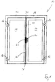
- FIG. 1 is a generally designated 10 door, which has a stationary leaf 12 and a moving wing 14. Both the inactive leaf 12 and the active leaf 14 are pivotally connected by hinges 16 to a frame 18.
- the active leaf 14 can be locked via a lock 20 with the inactive leaf 12 and the inactive leaf 12 has a floating bolt lock 22, to which an upper drive rod 24 and a lower drive rod 26 are coupled.
- the lower drive rod 26 engages with its downwardly facing free end 28 in the ground and the upper drive rod 24 engages with its upwardly facing free end 30 in the crossbar 32 of the frame 18 a.
- the lock 20 and the drive bolt lock 22 are opposite to each other, so that the latch of the lock 20 engages the drive bolt lock 22. Likewise, the latch of the lock 20 engages the drive bolt lock 22.
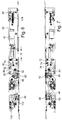
- FIGS. 2 and 3 show the drive bolt lock 22 without housing cover, wherein the drive bolt lock 22 is screwed to a cuff 34.
- a control slide 36 Inside the floating bolt lock 22 is a control slide 36 which has a one of the one end of a driving opening 38, on which the driver of a drive motor 40 engages over which the spool 36 in the longitudinal direction of the floating bolt lock 22 and parallel to the cuff 34 is displaceable.
- the spool 36 has a first cam 42 (see FIG. 8 ) With a first control section 44 and a second control section 46 for a Fallenauswerfer 48, which engages with a control pin 50 in the first control cam 42.
- the control pin 50 is guided in a transverse groove 52 in the housing base 54 such that the Fallenauswerfer 48 can move only transverse to the cuff 34.
- the spool 36 also has a second control cam 56 with a first control section 58 and a second control section 60 for a Bolt ejector 62, which engages with a control pin 64 in the second control cam 56.
- the control pin 64 is likewise guided in a transverse groove in the housing base 54 in such a manner that the bolt ejector 62 can move exclusively transversely to the cuff 34.
- Both cams 42 and 56 and in particular the two second control sections 44 and 58 each have a cutout 66, whose function will be explained later.
- the driver of the drive motor 40 is moved by a first distance 68 and thereby the spool 36 is moved to a first position.
- the two first control section 44 and 58 have the two control pins 50 and 64 of the Fallenauswerfers 48 and 60 Riegelauswerfers displaced transversely to the cuff 34 and placed the two ejectors 48 and 62 in a position in which this the latch and the latch of the lock 20 from the Eject the floating bolt lock 22.
- the leaf 14 can now be opened.
- the spool 36 also has a control slot 72, in which a pin 74 of a reversing lever 76 engages.
- the reversing lever 76 is pivotally mounted and has a first pivot arm 78, from which the pin 74 protrudes.
- the second pivot arm 80 engages behind with its hook-shaped end a driver pin 82 of a driver 84 which is displaceably mounted in the lock housing.
- a pull rod 86 is screwed, which extends to the lower end of the floating bolt lock 22 and to which a Einzugsschieber 88 is fixed for the lower drive rod 26.
- the driver 84 has a second driving pin 90, on which the hook-shaped end of a second coupling member 92 engages.
- the second coupling member 92 is pivotally mounted and forms with an extension a slot guide 94 for a pin 96 of a first rotatably mounted coupling member 98.
- the pin 96 is a sprocket portion 100 opposite, which meshes with a toothing 102 of a Nussschwenkhebels 104.
- the end of an arm 110 of a pull-in rocker 112 is coupled, which engages with an actuating finger 114 an intake slide 116.
- unactuated drive motor 40 (FIG. FIGS. 2 and 3 ) is the pin 74 at one end of the control slot 72 at.
- the pin 74 In the intermediate position of the drive motor 40 according to the FIGS. 4 and 5 the pin 74 is located at the other end of the Control slot 72, so that the lever 76 continues to assume its rest position. This means that although the trap ejector 48 and the latch ejector 62 assume their working position, the drive rods 24 and 26 are still pushed out.
- a first rotation of the pusher nut 106 in which the nut pivot lever 104 is entrained via the two lateral catches, causes a first rotation of the nut pivot lever 104 about the axis of the pusher nut 106, now serving the nut pivot lever 104 as a drive for the intake rocker, the first and second coupling member 98 and 92.
- the intake rocker 112 and the lever arm of the Nussschwenkhebels 104 form a Fallenauswerferantrieb and the two coupling members 92 and 98 a Riegelauswerferantrieb.
- the trap ejector 48 and the latch ejector 62 are ejected.
- the driving pin 82 of the driver 84 lifts off the reversing lever 76 and thereby the spool 36 is not actuated and remains in its rest position.
- a displacement of the Fallenauswerfers 48 and the Riegelauswerfers 62 can still take place, since the two control pins 50 and 64 can lift in the free punch 66 of the two control sections 44 and 58.
Description
Die Erfindung betrifft ein Treibriegelschloss für eine einen Standflügel und einen Gangflügel aufweisende Tür, mit einem Fallenauswerfer, einem parallel zu einer Stulp verschiebbaren Steuerschieber, einem Einzugsschieber,für eine Treibstange, wobei beim Betätigen des Steuerschiebers zuerst der Fallenauswerfer verschoben und anschließend der Einzugsschieber angetrieben werden.The invention relates to a drive bolt lock for a door wing and a power wing door having a Fallenauswerfer, a sliding parallel to a forend spool, a Einzugsschieber, for a drive rod, which displaced upon actuation of the spool first Fallenauswerfer and then the intake gate are driven.
Bei einer bevorzugten Fluchttürlösung für zweiflügelige Türen kommen üblicherweise Gangflügel- und Standflügelverschlusssysteme zum Einsatz. Auf der Standflügelseite werden sogenannte Treibriegelschlösser verwendet. Bei einer Panikbetätigung des Standflügelschlosses werden die obere und die untere Treibriegelstange eingezogen und gleichzeitig werden über Auslöseschieber die Falle und der Riegel des Gangflügelschlosses in den Schlosskasten zurückgedrückt, so dass das Türsystem geöffnet werden kann.In a preferred escape door solution for double-leaf doors usually flow wing and poppet closure systems are used. On the inactive side so-called bolt locks are used. In a panic actuation of the poppet lock, the upper and lower shoot bolt rod are retracted and at the same time are on the trigger slide, the latch and the latch Moving wing lock pushed back into the lock case, so that the door system can be opened.
Die
Soll nun ein zweiflügeliges Türsystem durch den Einsatz von Drehflügelantrieben automatisiert werden, müssen auch die Verschlusskomponenten elektrisch oder motorisch freigegeben werden. Dies geschieht heute mittels eines im Treibriegelschloss integrierten elektrischen Türöffners für die Freigabe der Falle des Gangflügelschlosses und eines in der Zarge eingebauten Türöffners für die Freigabe der oberen Treibriegelstange. Auf die untere Treibriegelstange muss verzichtet werden, da das Schloss nicht mechanisch, also über eine Handhabe betätigt wird und somit die Stangen keine Hubbewegung ausführen würden.If now a double-leaf door system is to be automated by the use of rotary vane drives, also the locking components must be released electrically or by motor. This is done today by means of an integrated in the floating bolt lock electric door opener for releasing the case of the moving wing lock and a built-in frame door opener for the release of the upper drive bolt rod. On the lower drive bolt bar must be dispensed with, since the lock is not mechanically, so operated by a handle and thus the rods would perform no lifting movement.
Diese Art der Konstruktion zwingt den Verwender mindestens zwei kostenintensive, für Feuerschutztüren geeignete elektrische Türöffner einzusetzen. Weiterhin schwächt die fehlende untere Treibriegelstange die Eigenschaften der Tür bezüglich ihrer ursprünglichen Eigenschaften in Bezug auf Feuerschutz, Rauchschutz und Einbruchhemmung.This type of construction forces the user to use at least two expensive electrical door openers suitable for fire doors. Furthermore, the missing bottom bolt bar weakens the properties of the door in terms of its original fire protection, smoke protection and burglar resistance properties.
Aus der
Der Erfindung liegt die Aufgabe zugrunde, ein zu der
Diese Aufgabe wird mit einem Treibriegelschloss der eingangs genannten Art erfindungsgemäß dadurch gelöst, dass der Steuerschieber über einen Steuerschlitz mit einem Umlenkhebel mit dem Einzugsschieber gekoppelt ist.This object is achieved with a floating bolt lock of the type mentioned in the present invention, that the spool is coupled via a control slot with a lever with the intake slide.
Das erfindungsgemäße Treibriegelschloss besitzt den wesentlichen Vorteil, dass aufgrund der zeitlichen Verzögerung des zweiten Bewegungsablaufes, d.h. der Entriegelung der Treibstange, zuerst die Falle des Gangflügelschlosses aus dem Treibriegelschloss ausgeschoben wird, so dass der Standflügel nach wie vor über die. Treibstange oder die Treibstangen verriegelt bleibt. Sodann erfolgt in einem zweiten Arbeitsschritt die Entriegelung der Treibstangen, so dass der Standflügel vollständig entriegelt ist. Er kann nunmehr ebenfalls geöffnet werden. Dies wird erfindungsgemäß dadurch erzielt, dass der Ausschub der Falle und der Einzug der Treibstangen zeitlich nacheinander erfolgen. Außerdem kann das erfindungsgemäße Treibriegelschloss nicht nur mittels eines Drückers manuell betätigt sondern auch motorisch angesteuert werden.The driving bolt lock according to the invention has the significant advantage that due to the time delay of the second movement sequence, i. the unlocking of the drive rod, first the case of the moving wing lock is pushed out of the drive bolt lock, so that the inactive wing still over the. Drive rod or the drive rods remains locked. Then, in a second step, the unlocking of the drive rods, so that the inactive leaf is completely unlocked. He can now also be opened. This is inventively achieved in that the ejection of the case and the collection of the drive rods are carried out in chronological succession. In addition, the invention can be manually operated by means of a pusher bolt lock but also controlled by a motor.
Das sequentielle motorisch angetriebene Treibriegelschloss teilt also den Gesamtbewegungsablauf beim Betätigen des Schlosses in zwei hintereinander ablaufende Bewegungsabläufe auf. Die Falle und gegebenenfalls ein Riegel des Gangflügelschlosses werden beim ersten Bewegungsablauf über den bzw. die Auswerfer ausgeschoben, was z.B. für die Verwendung von Zutrittskontrollsystemen oder die automatisierte Öffnung des Gangflügels erforderlich ist. Danach erfolgt mittels des zweiten Bewegungsablaufes das Einziehen der Treibriegelstangen, was für die zusätzliche Freigabe des Standflügels erforderlich ist.The sequential powered drive bolt lock thus divides the overall movement sequence when you press the lock in two successive courses of motion. The latch and possibly a latch of the moving wing lock are pushed out over the ejector (s) during the first movement, which is required, for example, for the use of access control systems or the automated opening of the active leaf. Thereafter, by means of the second movement sequence, the retraction of the drive bolt rods, which is required for the additional release of the passive leaf.
Im Gegensatz zu den oben erwähnten herkömmlichen Konstruktionen können bei der Erfindung die Elektroöffner eingespart und sowohl die obere als auch die untere Treibriegelstange verwendet werden.In contrast to the above-mentioned conventional constructions, the invention can spare the electric openers and use both the upper and lower drive bolt rods.
Ein weiterer Vorteil besteht darin, dass mittels des Steuerschiebers zwar der Fallenauswerfer direkt betätigt, der Einzugsschieber aber über einen Umlenkhebel angetrieben werden. Der Umlenkhebel ist schwenkbar gelagert und weist zwei Hebelarme auf, wobei der eine Hebelarm für den Antrieb über den Steuerschieber und der andere Hebelarm für den Abtrieb dient. Die Länge der Hebelarme kann so eingestellt werden, dass optimale Bewegungsabläufe für den Einzugsschieber erreicht werden. Die Antriebsmotoren können dadurch kleiner gestaltet werden und finden nunmehr Platz im Gehäuse des Treibriegelschlosses.Another advantage is that by means of the spool while the fall ejector directly actuated, the intake gate but are driven by a lever. The lever is pivotally mounted and has two lever arms, wherein one lever arm for driving via the spool and the other lever arm for the output is used. The length of the lever arms can be adjusted so that optimum movement sequences are achieved for the intake slide. The drive motors can thereby be made smaller and now find room in the housing of the floating bolt lock.
Bei einer Weiterbildung des erfindungsgemäßen Treibriegelschlosses ist der Steuerschieber ausschließlich motorisch antreibbar, insbesondere verschiebbar. Bei einer manuellen Betätigung mittels eines Drückers oder einer Drückersange bleibt der Steuerschieber in Ruhe und wird nicht verlagert. Hierdurch werden die Betätigungskräfte reduziert und es bedarf keines Freilaufs für den mit dem Steuerschieber gekoppelten Antriebsmotor.In a further development of the floating bolt lock according to the invention, the spool is driven exclusively by a motor, in particular displaceable. With a manual operation by means of a pusher or a pusher, the spool remains at rest and is not displaced. As a result, the actuating forces are reduced and it requires no freewheel for the coupled with the spool drive motor.
Bei einer bevorzugten Weiterbildung des Treibriegelschlosses weist der Steuerschieber eine erste Steuerkurve mit einem ersten und einem zweiten Steuerabschnitt für den Fallenauswerfer auf, wobei über den ersten Steuerabschnitt der Fallenauswerfer ausgeworfen wird, und der erste Steuerabschnitt einen Freischnitt aufweist, über den ein Steuerelement des Fallenauswerfers vom ersten Steuerabschnitt abheben kann. Befindet sich der Steuerschieber in seiner Ruhelage, dann kann der Fallenauswerfer dennoch manuell ausgeschoben werden, was durch den Freischnitt im Steuerschieber ermöglicht wird.In a preferred embodiment of the floating bolt lock, the spool has a first Control cam having a first and a second control section for the Fallenauswerfer, wherein over the first control portion of the Fallenauswerfer is ejected, and the first control section has a free cut over which a control of the Fallenauswerfers can lift from the first control section. If the spool is in its rest position, then the fall ejector can still be pushed out manually, which is made possible by the free cut in the spool.
Sollte das Gangflügelschloss nicht nur mit einer Falle sondern auch mit einem Riegel versehen sein, dann weist der Steuerschieber des erfindungsgemäßen Treibriegelschlosses eine zweite Steuerkurve mit einem ersten und einem zweiten Steuerabschnitt für einen Riegelauswerfer auf, wobei über den ersten Steuerabschnitt der Riegelauswerfer ausgeworfen wird, und der erste Steuerabschnitt einen Freischnitt aufweist, über den das Steuerelement des Riegelauswerfers vom ersten Steuerabschnitt abheben kann. Somit besteht auch für den Riegelauswerfer die Möglichkeit, dass dieser manuell betätigt werden kann, ohne dass der Steuerschieber verlagert wird.If the aileron lock not only be provided with a trap but also with a bolt, then the spool of the floating bolt lock according to the invention on a second control cam with a first and a second control section for a Biegelauswerfer, being discharged over the first control section of the Bolt ejector, and first control section has a free cut over which the control of the Riegelauswerfers can lift off from the first control section. Thus, it is also possible for the Latch ejector that this can be manually operated without the spool is displaced.
Der Freischnitt weist einen dreieckförmigen Querschnitt auf, so dass der Fallenauswerfer und/oder der Riegelauswerfer in jeder Lage des Steuerschiebers manuell ausgeworfen werden können.The cutout has a triangular cross-section so that the trap ejector and / or the latch ejector can be manually ejected in any position of the control slide.
Eine Weiterbildung des Treibriegelschlosses sieht eine Drückernuss und einem von der Drückernuss antreibbaren Nussschwenkhebel vor, mit dem direkt oder indirekt der Fallenauswerfer ausschiebbar ist. Das Treibriegelschloss kann bei dieser Ausgestaltung nicht nur über eine Betätigung des Steuerschiebers sondern auch über einen Drücker oder eine Drückerstange manuell betätigt werden. Durch mehr oder weniger weites Niederdrücken des Drückers wird nur die Falle ausgeschoben oder es wird das gesamte Treibriegelschloss entriegelt und der Standflügel kann aufgeschwenkt werden.A refinement of the floating bolt lock provides for a follower and a nut pivoting lever that can be driven by the follower, with which the trap ejector can be pushed out directly or indirectly. The floating bolt lock can be manually operated in this embodiment not only via an actuation of the spool but also via a pusher or a presser bar. By more or less pressing down the pusher only the case is ejected or it is the entire bolt lock unlocked and the inactive leaf can be swung open.
Mit Vorzug ist der Nussschwenkhebel mit einer schwenkbar gelagerten Einzugsschwinge für den Einzugsschieber für die Treibstange gekoppelt. Die Einzugsschwinge ist schwenkbar gelagert und weist einen mit dem Einzugsschieber und einen mit dem Nussschwenkhebel gekoppelten Schwingenarm auf, so dass durch geeignete Wahl der Armlängen optimale Hebelverhältnisse eingestellt werden können.With preference, the nut pivot lever is coupled to a pivotally mounted pull-in rocker for the pull-in slider for the drive rod. The intake rocker is pivotally mounted and has a with the intake gate and a coupled with the Nussschwenkhebel rocker arm, so that optimal leverage ratios can be adjusted by a suitable choice of arm lengths.
Um bei einer motorischen Betätigung des Treibriegelschlosses, also wenn der Steuerschieber im Schlossgehäuse verlagert wird, zu vermeiden, dass die Drückernuss gedreht wird, ist der Nussschwenkhebel über einen Freilauf mit der Drückernuss gekoppelt.In order to avoid a movement of the driving bolt lock, ie when the spool is moved in the lock housing, to avoid that the follower is rotated, the Nussschwenkhebel is coupled via a freewheel with the follower.
Eine Weiterbildung des Treibriegelschlosses sieht vor, dass der Nussschwenkhebel mit einem drehbar gelagerten ersten Koppelglied kämmt, welches einen Riegelauswerfer ausschiebt. Dabei ist das erste Koppelglied mit einem zweiten Koppelglied gekoppelt und das zweite Koppelglied treibt einen zweiten Einzugsschieber für eine zweite Treibstange an.A further development of the floating bolt lock provides that the nut pivoting lever meshes with a rotatably mounted first coupling member which pushes out a bolt ejector. In this case, the first coupling member is coupled to a second coupling member and the second coupling member drives a second Einzugsschieber for a second drive rod.
Vorzugsweise sind mittels des Umlenkhebels der zweite Einzugsschieber, das ersten und zweite Kopplungsglied, der Nussschwenkhebel, die Einzugsschwinge und der erste Einzugsschieber betätigbar. Der erste Einzugsschieber besitzt also keine direkte Verbindung zum Steuerschieber.Preferably, by means of the reversing lever of the second Einzugsschieber, the first and second coupling member, the Nussschwenkhebel, the intake rocker and the first Einzugsschieber actuated. The first intake slide thus has no direct connection to the spool.
Weitere Vorteile, Merkmale und Einzelheiten der Erfindung ergeben sich aus den Unteransprüchen sowie der nachfolgenden Beschreibung, in der unter Bezugnahme auf die Zeichnung ein besonders bevorzugtes Ausführungsbeispiel im Einzelnen beschrieben ist.Further advantages, features and details of the invention will become apparent from the dependent claims and the in the following description, in which a particularly preferred embodiment is described in detail with reference to the drawing.
In der Zeichnung zeigen:
Figur 1- eine schematische Darstellung einer zweiflügeligen Tür mit einem Gang- und einem Standflügel;
- Figur 2
- eine Draufsicht auf ein Ausführungsbeispiel des erfindungsgemäßen Treibstangenschlosses bei abgenommener Schlossdecke, wobei das Schloss sich in der Grundstellung befindet;
- Figur 3
- eine Ansicht auf die Rückseite des Treibstangenschlosses gemäß
Figur 2 bei abgenommenem Schlossboden; - Figur 4
- das Schloss gemäß
Figur 2 mit teilweise verschobenem Steuerschieber; - Figur 5
- eine Ansicht auf die Rückseite des Treibstangenschlosses gemäß
Figur 4 ; - Figur 6
- das Schloss gemäß
Figur 2 mit vollständig verschobenem Steuerschieber; - Figur 7
- eine Ansicht auf die Rückseite des Treibstangenschlosses gemäß
Figur 6 ; und Figur 8- eine Explosionsdarstellung des erfindungsgemäßen Treibstangenschlosses.
- FIG. 1
- a schematic representation of a two-leaf door with a gangway and a passive wing;
- FIG. 2
- a plan view of an embodiment of the espagnolette lock according to the invention with the lock cover removed, the lock is in the normal position;
- FIG. 3
- a view on the back of the espagnolette lock according to
FIG. 2 with removed lock bottom; - FIG. 4
- the castle according to
FIG. 2 with partially shifted spool valve; - FIG. 5
- a view on the back of the espagnolette lock according to
FIG. 4 ; - FIG. 6
- the castle according to
FIG. 2 with completely shifted spool; - FIG. 7
- a view on the back of the espagnolette lock according to
FIG. 6 ; and - FIG. 8
- an exploded view of the espagnolette lock according to the invention.
In der
Die
Der Steuerschieber 36 weist außerdem eine zweite Steuerkurve 56 mit einem ersten Steuerabschnitt 58 und einem zweiten Steuerabschnitt 60 für einen Riegelauswerfer 62 auf, der mit einem Steuerzapfen 64 in die zweite Steuerkurve 56 eingreift. Der Steuerzapfen 64 ist ebenfalls in einer Quernut im Gehäuseboden 54 derart geführt, dass der Riegelauswerfer 62 sich ausschließlich quer zur Stulpe 34 bewegen kann. Beide Steuerkurven 42 und 56 und insbesondere die beiden zweiten Steuerabschnitte 44 und 58 besitzen jeweils einen Freischnitt 66, dessen Funktion später erläutert wird.The
In den
In den
Der Steuerschieber 36 weist außerdem einen Steuerschlitz 72 auf, in welchen ein Zapfen 74 eines Umlenkhebels 76 eingreift. Der Umlenkhebel 76 ist schwenkbar gelagert und weist einen ersten Schwenkarm 78 auf, von welchem der Zapfen 74 abragt. Der zweite Schwenkarm 80 hintergreift mit seinem hakenförmigen Ende einen Mitnehmerzapfen 82 eines Mitnehmers 84, der verschieblich im Schlossgehäuse gelagert ist. An diesem Mitnehmer 84 ist eine Zugstange 86 angeschraubt, die bis ans untere Ende des Treibriegelschlosses 22 reicht und an welchem ein Einzugsschieber 88 für die untere Treibstange 26 befestigt ist.The
Der Mitnehmer 84 besitzt einen zweiten Mitnehmerzapfen 90, an welchem das hakenförmige Ende eines zweiten Koppelgliedes 92 angreift. Das zweite Koppelglied 92 ist verschwenkbar gelagert und bildet mit einem Fortsatz eine Schlitzführung 94 für einen Zapfen 96 eines ersten, drehbar gelagerten Koppelgliedes 98. Dem Zapfen 96 liegt ein Zahnkranzabschnitt 100 gegenüber, der mit einer Verzahnung 102 eines Nussschwenkhebels 104 kämmt. In den Nussschwenkhebel 104 greifen zwei Mitnehmer einer Drückernuss 106 und am freien Ende des Hebelarms 108 ist das Ende eines Arms 110 einer Einzugsschwinge 112 angekoppelt, die mit einem Betätigungsfinger 114 einen Einzugsschieber 116 hintergreift.The
Bei unbetätigtem Antriebsmotor 40 (
In der betätigten Endstellung des Antriebsmotors 40, die in den
Auf diese Weise werden während des zweiten Betätigungsabschnittes des Antriebsmotors 40, d.h. erst nach dem Auswerfen des Fallenauswerfers 48 und des Riegelauswerfers 62, durch Betätigen des Umlenkhebels 76 die Zugstange 86 mit Einzugsschieber 88 und mittels der Einzugsschwinge 112 der Einzugsschieber 116 eingezogen und dadurch die beiden Treibstangen 24 und 26 aus dem Querbalken 32 und dem Boden gelöst.In this way, during the second operating portion of the
Wird das erfindungsgemäße Treibstangenschloss 22 manuell mittels eines Drückers oder einer Druckstange betätigt, dann bewirkt eine erste Drehung der Drückernuss 106, bei welcher der Nussschwenkhebel 104 über die beiden seitlichen Mitnehmer mitgenommen wird, eine erste Drehung des Nussschwenkhebels 104 um die Achse der Drückernuss 106, wobei nun der Nussschwenkhebel 104 als Antrieb für die Einzugsschwinge, das erste und das zweite Koppelglied 98 und 92 dient. Die Einzugsschwinge 112 und der Hebelarm des Nussschwenkhebels 104 bilden einen Fallenauswerferantrieb und die beiden Koppelglieder 92 und 98 einen Riegelauswerferantrieb. Der Fallenauswerfer 48 und der Riegelauswerfer 62 werden ausgeworfen. Mittels der Einzugsschwinge 112 und des zweiten Koppelgliedes 92 werden aber auch die beiden Einzugsschieber 116 und 88 eingezogen. Von Vorteil ist, dass der Mitnehmerzapfen 82 des Mitnehmers 84 vom Umlenkhebel 76 abhebt und dadurch der Steuerschieber 36 nicht betätigt wird und in seiner Ruhelage verbleibt. Ein Verschieben des Fallenauswerfers 48 und des Riegelauswerfers 62 kann dennoch erfolgen, da die beiden Steuerzapfen 50 und 64 im Freischnitt 66 von den beiden Steuerabschnitten 44 und 58 abheben können.If the
Selbst wenn nun der Antriebsmotor 40 betätigt wird, wird lediglich der Steuerschieber 36 verfahren, so dass die beiden Steuerzapfen 50 und 64 aus dem Freischnitt 66 in die beiden ersten Steuerabschnitte 46 und 60 einfahren und sich der Umlenkhebel 76 mit deinem zweiten Schwenkarm 80 am Mitnehmerzapfen 82 anlegt. Eine Rückstellung und definierte Ruhelage erhalten die Bauteile über eine Rückstellfeder 118, die den Einzugsschieber 88 in seine ausgefahrene Lage drängt, was in den
Claims (11)
- A drive bolt lock (22) for a door (10) having a fixed leaf (12) and an active leaf (14) comprising a falling latch ejector (48), a control slider (36) that can be moved parallel to a forend (34), and a retracting slider (88, 116) for a driving rod (24, 26), wherein upon actuation of the control slider (36) first the falling latch ejector (48) is moved and then the retracting slider (88, 116) is driven, characterized in that the control slider (36) is coupled to the retracting slider (88, 116) via a control slot (72) with a deflexion lever (76).
- The drive bolt lock according to claim 1, characterized in that the control slider (36) is exclusively drivable, in particular displaceable, by motor.
- The drive bolt lock according to claim 1 or 2, characterized in that the control slider (36) comprises a first control curve (42) having first and second control segments (44, 46) for the falling latch ejector (48) and that the falling latch ejector (48) is ejected via the first control segment (44), wherein the first control segment (44) has a cut-out (66), via which the control element (50) of the falling latch ejector (48) can lift off the first control segment (44).
- The drive bolt lock according to any one of the preceding claims, characterized in that the control slider (36) comprises a second control curve (56) having first and second control segments (58, 60) for a bolt ejector (62) and that the bolt ejector (62) is ejected via the first control segment (58), wherein the first control segment (58) has a cut-out (66), via which the control element (64) of the bolt ejector (62) can lift off the first control segment (44).
- The drive bolt lock according to claim 3 or 4, characterized in that the cut-out (66) is triangular.
- The drive bolt lock according to any one of the preceding claims, characterized by a follower (106) and a follower pivot lever (104) drivable by the follower (106), by which the falling latch ejector (48) can be pushed out directly or indirectly.
- The drive bolt lock according to claim 6, characterized in that the pivot lever (104) is coupled to a pivotally supported retracting swing element (112) for the retracting slider (116) for the driving rod (24).
- The drive bolt lock according to claim 6 or 7, characterized in that the follower pivot lever (104) is coupled to the follower (106) via a freewheel.
- The drive bolt lock according any one of claims 6 to 8, characterized in that the follower pivot lever (104) meshes with a pivotally supported first coupling member (98), which pushes out a bolt ejector (62).
- The drive bolt lock according to claim 9, characterized in that the first coupling member (98) is coupled to a second coupling member (92) and that the second coupling member (92) drives a second retracting slider (88) for a second driving rod (26).
- The drive bolt lock according to claims 7 and 10, characterized in that the second retracting slider (88), the first and second coupling members (98, 92), the follower pivot lever (104), the retracting swing element (112) and the first retracting slider (116) can be actuated by means of the deflexion lever (76).
Priority Applications (2)
| Application Number | Priority Date | Filing Date | Title |
|---|---|---|---|
| PL12199563T PL2749721T3 (en) | 2012-12-28 | 2012-12-28 | Drive bolt lock |
| EP12199563.3A EP2749721B1 (en) | 2012-12-28 | 2012-12-28 | Drive bolt lock |
Applications Claiming Priority (1)
| Application Number | Priority Date | Filing Date | Title |
|---|---|---|---|
| EP12199563.3A EP2749721B1 (en) | 2012-12-28 | 2012-12-28 | Drive bolt lock |
Publications (2)
| Publication Number | Publication Date |
|---|---|
| EP2749721A1 EP2749721A1 (en) | 2014-07-02 |
| EP2749721B1 true EP2749721B1 (en) | 2016-08-24 |
Family
ID=47561249
Family Applications (1)
| Application Number | Title | Priority Date | Filing Date |
|---|---|---|---|
| EP12199563.3A Active EP2749721B1 (en) | 2012-12-28 | 2012-12-28 | Drive bolt lock |
Country Status (2)
| Country | Link |
|---|---|
| EP (1) | EP2749721B1 (en) |
| PL (1) | PL2749721T3 (en) |
Cited By (1)
| Publication number | Priority date | Publication date | Assignee | Title |
|---|---|---|---|---|
| EP3543439A1 (en) | 2018-03-22 | 2019-09-25 | dormakaba Deutschland GmbH | Method for a lock assembly |
Families Citing this family (2)
| Publication number | Priority date | Publication date | Assignee | Title |
|---|---|---|---|---|
| DE202015103708U1 (en) * | 2015-07-15 | 2015-08-25 | Heinrich Strenger GmbH & Co. KG | Canister with electric motor |
| DE102018106832A1 (en) * | 2018-03-22 | 2019-09-26 | Dormakaba Deutschland Gmbh | Counter lock for a wing door |
Family Cites Families (3)
| Publication number | Priority date | Publication date | Assignee | Title |
|---|---|---|---|---|
| DE202006001383U1 (en) * | 2006-01-27 | 2006-04-13 | Bks Gmbh | Shot-bolt lock |
| DE202007000599U1 (en) | 2007-01-10 | 2007-03-15 | Kfv Karl Fliether Gmbh & Co. Kg | Lock fitting for door which has hinged inactive leaf and hinged active leaf has at least one slide provided in housing of shoot bolt lock and has two coupling devices arranged with offset in relation to each other |
| DE102009025469B3 (en) | 2009-06-15 | 2011-04-14 | Bks Gmbh | Shoot bolt lock |
-
2012
- 2012-12-28 EP EP12199563.3A patent/EP2749721B1/en active Active
- 2012-12-28 PL PL12199563T patent/PL2749721T3/en unknown
Cited By (1)
| Publication number | Priority date | Publication date | Assignee | Title |
|---|---|---|---|---|
| EP3543439A1 (en) | 2018-03-22 | 2019-09-25 | dormakaba Deutschland GmbH | Method for a lock assembly |
Also Published As
| Publication number | Publication date |
|---|---|
| PL2749721T3 (en) | 2017-02-28 |
| EP2749721A1 (en) | 2014-07-02 |
Similar Documents
| Publication | Publication Date | Title |
|---|---|---|
| EP1932989B1 (en) | Locking device for doors, windows or similar, in particular an espagnolette lock with panic function and multi-point locking | |
| EP2951369B1 (en) | Panic lock | |
| DE102006059568B4 (en) | Locking system for doors, windows or the like, in particular espagnolette lock with panic function and multipoint locking | |
| EP2264268B1 (en) | Drive bar lock | |
| EP0798436A2 (en) | Locking device | |
| EP1574644A2 (en) | Locking system for doors, windows or similar, in particular espagnolette lock with anti-panic function and multiple lock points | |
| EP0942135B2 (en) | Locking device | |
| EP2749721B1 (en) | Drive bolt lock | |
| EP3144455B1 (en) | Locking device | |
| EP2072725A2 (en) | Espagnolette locking device | |
| DE202005000939U1 (en) | Locking arrangement for door or window with drive rods 30 connecting auxiliary locks to main lock has pressure knob on main lock with pivoting lever moving bolt and drive rods | |
| EP2339096B1 (en) | Connecting rod lock with panic function and multiple locking | |
| EP1234938A2 (en) | Espagnolette lock | |
| EP2072723A2 (en) | Espagnolette locking device | |
| DE2738746B2 (en) | Release device for a panic door lock with latch and bolt | |
| DE3831529C2 (en) | Espagnolette lock | |
| EP1617018B1 (en) | Electromechanical door lock | |
| EP3122965B1 (en) | Panic lock | |
| DE102008015655A1 (en) | panic lock | |
| EP0972900B1 (en) | Espagnolette lock | |
| EP0974721B1 (en) | Lock with several bolts | |
| DE102013013547A1 (en) | Lock with latch with unlocking pin | |
| EP0823521B1 (en) | Espagnolette lock | |
| EP2320013B1 (en) | Fitting with a reversing gear | |
| DE202022106561U1 (en) | locking device |
Legal Events
| Date | Code | Title | Description |
|---|---|---|---|
| 17P | Request for examination filed |
Effective date: 20140103 |
|
| AK | Designated contracting states |
Kind code of ref document: A1 Designated state(s): AL AT BE BG CH CY CZ DE DK EE ES FI FR GB GR HR HU IE IS IT LI LT LU LV MC MK MT NL NO PL PT RO RS SE SI SK SM TR |
|
| AX | Request for extension of the european patent |
Extension state: BA ME |
|
| PUAI | Public reference made under article 153(3) epc to a published international application that has entered the european phase |
Free format text: ORIGINAL CODE: 0009012 |
|
| GRAP | Despatch of communication of intention to grant a patent |
Free format text: ORIGINAL CODE: EPIDOSNIGR1 |
|
| RIC1 | Information provided on ipc code assigned before grant |
Ipc: E05C 9/04 20060101ALI20160226BHEP Ipc: E05C 7/04 20060101AFI20160226BHEP Ipc: E05B 47/00 20060101ALI20160226BHEP Ipc: E05B 63/24 20060101ALI20160226BHEP Ipc: E05B 65/10 20060101ALI20160226BHEP |
|
| INTG | Intention to grant announced |
Effective date: 20160318 |
|
| RIN1 | Information on inventor provided before grant (corrected) |
Inventor name: SCHOPPA, ALFRED Inventor name: VADALA, JONATHAN Inventor name: KNAPPIK, DANIEL Inventor name: HENNECKE, GERHARD |
|
| GRAS | Grant fee paid |
Free format text: ORIGINAL CODE: EPIDOSNIGR3 |
|
| GRAA | (expected) grant |
Free format text: ORIGINAL CODE: 0009210 |
|
| AK | Designated contracting states |
Kind code of ref document: B1 Designated state(s): AL AT BE BG CH CY CZ DE DK EE ES FI FR GB GR HR HU IE IS IT LI LT LU LV MC MK MT NL NO PL PT RO RS SE SI SK SM TR |
|
| REG | Reference to a national code |
Ref country code: GB Ref legal event code: FG4D Free format text: NOT ENGLISH |
|
| REG | Reference to a national code |
Ref country code: CH Ref legal event code: EP |
|
| REG | Reference to a national code |
Ref country code: AT Ref legal event code: REF Ref document number: 823272 Country of ref document: AT Kind code of ref document: T Effective date: 20160915 |
|
| REG | Reference to a national code |
Ref country code: IE Ref legal event code: FG4D Free format text: LANGUAGE OF EP DOCUMENT: GERMAN |
|
| REG | Reference to a national code |
Ref country code: CH Ref legal event code: NV Representative=s name: DREISS PATENTANWAELTE PARTG MBB, DE |
|
| REG | Reference to a national code |
Ref country code: DE Ref legal event code: R096 Ref document number: 502012008046 Country of ref document: DE |
|
| REG | Reference to a national code |
Ref country code: NL Ref legal event code: FP |
|
| REG | Reference to a national code |
Ref country code: FR Ref legal event code: PLFP Year of fee payment: 5 |
|
| REG | Reference to a national code |
Ref country code: LT Ref legal event code: MG4D |
|
| PG25 | Lapsed in a contracting state [announced via postgrant information from national office to epo] |
Ref country code: RS Free format text: LAPSE BECAUSE OF FAILURE TO SUBMIT A TRANSLATION OF THE DESCRIPTION OR TO PAY THE FEE WITHIN THE PRESCRIBED TIME-LIMIT Effective date: 20160824 Ref country code: FI Free format text: LAPSE BECAUSE OF FAILURE TO SUBMIT A TRANSLATION OF THE DESCRIPTION OR TO PAY THE FEE WITHIN THE PRESCRIBED TIME-LIMIT Effective date: 20160824 Ref country code: NO Free format text: LAPSE BECAUSE OF FAILURE TO SUBMIT A TRANSLATION OF THE DESCRIPTION OR TO PAY THE FEE WITHIN THE PRESCRIBED TIME-LIMIT Effective date: 20161124 Ref country code: HR Free format text: LAPSE BECAUSE OF FAILURE TO SUBMIT A TRANSLATION OF THE DESCRIPTION OR TO PAY THE FEE WITHIN THE PRESCRIBED TIME-LIMIT Effective date: 20160824 Ref country code: LT Free format text: LAPSE BECAUSE OF FAILURE TO SUBMIT A TRANSLATION OF THE DESCRIPTION OR TO PAY THE FEE WITHIN THE PRESCRIBED TIME-LIMIT Effective date: 20160824 |
|
| PG25 | Lapsed in a contracting state [announced via postgrant information from national office to epo] |
Ref country code: PT Free format text: LAPSE BECAUSE OF FAILURE TO SUBMIT A TRANSLATION OF THE DESCRIPTION OR TO PAY THE FEE WITHIN THE PRESCRIBED TIME-LIMIT Effective date: 20161226 Ref country code: SE Free format text: LAPSE BECAUSE OF FAILURE TO SUBMIT A TRANSLATION OF THE DESCRIPTION OR TO PAY THE FEE WITHIN THE PRESCRIBED TIME-LIMIT Effective date: 20160824 Ref country code: ES Free format text: LAPSE BECAUSE OF FAILURE TO SUBMIT A TRANSLATION OF THE DESCRIPTION OR TO PAY THE FEE WITHIN THE PRESCRIBED TIME-LIMIT Effective date: 20160824 Ref country code: GR Free format text: LAPSE BECAUSE OF FAILURE TO SUBMIT A TRANSLATION OF THE DESCRIPTION OR TO PAY THE FEE WITHIN THE PRESCRIBED TIME-LIMIT Effective date: 20161125 Ref country code: LV Free format text: LAPSE BECAUSE OF FAILURE TO SUBMIT A TRANSLATION OF THE DESCRIPTION OR TO PAY THE FEE WITHIN THE PRESCRIBED TIME-LIMIT Effective date: 20160824 |
|
| PG25 | Lapsed in a contracting state [announced via postgrant information from national office to epo] |
Ref country code: RO Free format text: LAPSE BECAUSE OF FAILURE TO SUBMIT A TRANSLATION OF THE DESCRIPTION OR TO PAY THE FEE WITHIN THE PRESCRIBED TIME-LIMIT Effective date: 20160824 Ref country code: EE Free format text: LAPSE BECAUSE OF FAILURE TO SUBMIT A TRANSLATION OF THE DESCRIPTION OR TO PAY THE FEE WITHIN THE PRESCRIBED TIME-LIMIT Effective date: 20160824 |
|
| REG | Reference to a national code |
Ref country code: DE Ref legal event code: R097 Ref document number: 502012008046 Country of ref document: DE |
|
| PG25 | Lapsed in a contracting state [announced via postgrant information from national office to epo] |
Ref country code: BG Free format text: LAPSE BECAUSE OF FAILURE TO SUBMIT A TRANSLATION OF THE DESCRIPTION OR TO PAY THE FEE WITHIN THE PRESCRIBED TIME-LIMIT Effective date: 20161124 Ref country code: SM Free format text: LAPSE BECAUSE OF FAILURE TO SUBMIT A TRANSLATION OF THE DESCRIPTION OR TO PAY THE FEE WITHIN THE PRESCRIBED TIME-LIMIT Effective date: 20160824 Ref country code: SK Free format text: LAPSE BECAUSE OF FAILURE TO SUBMIT A TRANSLATION OF THE DESCRIPTION OR TO PAY THE FEE WITHIN THE PRESCRIBED TIME-LIMIT Effective date: 20160824 Ref country code: CZ Free format text: LAPSE BECAUSE OF FAILURE TO SUBMIT A TRANSLATION OF THE DESCRIPTION OR TO PAY THE FEE WITHIN THE PRESCRIBED TIME-LIMIT Effective date: 20160824 Ref country code: DK Free format text: LAPSE BECAUSE OF FAILURE TO SUBMIT A TRANSLATION OF THE DESCRIPTION OR TO PAY THE FEE WITHIN THE PRESCRIBED TIME-LIMIT Effective date: 20160824 Ref country code: BE Free format text: LAPSE BECAUSE OF NON-PAYMENT OF DUE FEES Effective date: 20161231 |
|
| PLBE | No opposition filed within time limit |
Free format text: ORIGINAL CODE: 0009261 |
|
| STAA | Information on the status of an ep patent application or granted ep patent |
Free format text: STATUS: NO OPPOSITION FILED WITHIN TIME LIMIT |
|
| 26N | No opposition filed |
Effective date: 20170526 |
|
| GBPC | Gb: european patent ceased through non-payment of renewal fee |
Effective date: 20161228 |
|
| PG25 | Lapsed in a contracting state [announced via postgrant information from national office to epo] |
Ref country code: SI Free format text: LAPSE BECAUSE OF FAILURE TO SUBMIT A TRANSLATION OF THE DESCRIPTION OR TO PAY THE FEE WITHIN THE PRESCRIBED TIME-LIMIT Effective date: 20160824 |
|
| PG25 | Lapsed in a contracting state [announced via postgrant information from national office to epo] |
Ref country code: MC Free format text: LAPSE BECAUSE OF FAILURE TO SUBMIT A TRANSLATION OF THE DESCRIPTION OR TO PAY THE FEE WITHIN THE PRESCRIBED TIME-LIMIT Effective date: 20160824 |
|
| REG | Reference to a national code |
Ref country code: IE Ref legal event code: MM4A |
|
| PG25 | Lapsed in a contracting state [announced via postgrant information from national office to epo] |
Ref country code: LU Free format text: LAPSE BECAUSE OF NON-PAYMENT OF DUE FEES Effective date: 20161228 |
|
| PG25 | Lapsed in a contracting state [announced via postgrant information from national office to epo] |
Ref country code: GB Free format text: LAPSE BECAUSE OF NON-PAYMENT OF DUE FEES Effective date: 20161228 Ref country code: IE Free format text: LAPSE BECAUSE OF NON-PAYMENT OF DUE FEES Effective date: 20161228 |
|
| REG | Reference to a national code |
Ref country code: FR Ref legal event code: PLFP Year of fee payment: 6 |
|
| REG | Reference to a national code |
Ref country code: BE Ref legal event code: MM Effective date: 20161231 |
|
| REG | Reference to a national code |
Ref country code: DE Ref legal event code: R082 Ref document number: 502012008046 Country of ref document: DE |
|
| PG25 | Lapsed in a contracting state [announced via postgrant information from national office to epo] |
Ref country code: HU Free format text: LAPSE BECAUSE OF FAILURE TO SUBMIT A TRANSLATION OF THE DESCRIPTION OR TO PAY THE FEE WITHIN THE PRESCRIBED TIME-LIMIT; INVALID AB INITIO Effective date: 20121228 |
|
| PG25 | Lapsed in a contracting state [announced via postgrant information from national office to epo] |
Ref country code: MK Free format text: LAPSE BECAUSE OF FAILURE TO SUBMIT A TRANSLATION OF THE DESCRIPTION OR TO PAY THE FEE WITHIN THE PRESCRIBED TIME-LIMIT Effective date: 20160824 Ref country code: IS Free format text: LAPSE BECAUSE OF FAILURE TO SUBMIT A TRANSLATION OF THE DESCRIPTION OR TO PAY THE FEE WITHIN THE PRESCRIBED TIME-LIMIT Effective date: 20160824 Ref country code: CY Free format text: LAPSE BECAUSE OF FAILURE TO SUBMIT A TRANSLATION OF THE DESCRIPTION OR TO PAY THE FEE WITHIN THE PRESCRIBED TIME-LIMIT Effective date: 20160824 |
|
| PG25 | Lapsed in a contracting state [announced via postgrant information from national office to epo] |
Ref country code: MT Free format text: LAPSE BECAUSE OF FAILURE TO SUBMIT A TRANSLATION OF THE DESCRIPTION OR TO PAY THE FEE WITHIN THE PRESCRIBED TIME-LIMIT Effective date: 20160824 |
|
| PG25 | Lapsed in a contracting state [announced via postgrant information from national office to epo] |
Ref country code: AL Free format text: LAPSE BECAUSE OF FAILURE TO SUBMIT A TRANSLATION OF THE DESCRIPTION OR TO PAY THE FEE WITHIN THE PRESCRIBED TIME-LIMIT Effective date: 20160824 Ref country code: TR Free format text: LAPSE BECAUSE OF FAILURE TO SUBMIT A TRANSLATION OF THE DESCRIPTION OR TO PAY THE FEE WITHIN THE PRESCRIBED TIME-LIMIT Effective date: 20160824 |
|
| PGFP | Annual fee paid to national office [announced via postgrant information from national office to epo] |
Ref country code: PL Payment date: 20221215 Year of fee payment: 11 |
|
| PGFP | Annual fee paid to national office [announced via postgrant information from national office to epo] |
Ref country code: CH Payment date: 20230103 Year of fee payment: 11 |
|
| P01 | Opt-out of the competence of the unified patent court (upc) registered |
Effective date: 20230509 |
|
| PGFP | Annual fee paid to national office [announced via postgrant information from national office to epo] |
Ref country code: NL Payment date: 20231220 Year of fee payment: 12 Ref country code: IT Payment date: 20231228 Year of fee payment: 12 Ref country code: FR Payment date: 20231221 Year of fee payment: 12 Ref country code: DE Payment date: 20231214 Year of fee payment: 12 Ref country code: AT Payment date: 20231221 Year of fee payment: 12 |
|
| PGFP | Annual fee paid to national office [announced via postgrant information from national office to epo] |
Ref country code: PL Payment date: 20231214 Year of fee payment: 12 |