EP2749721B1 - Crémone espagnolette - Google Patents
Crémone espagnolette Download PDFInfo
- Publication number
- EP2749721B1 EP2749721B1 EP12199563.3A EP12199563A EP2749721B1 EP 2749721 B1 EP2749721 B1 EP 2749721B1 EP 12199563 A EP12199563 A EP 12199563A EP 2749721 B1 EP2749721 B1 EP 2749721B1
- Authority
- EP
- European Patent Office
- Prior art keywords
- control
- bolt lock
- slider
- ejector
- lock according
- Prior art date
- Legal status (The legal status is an assumption and is not a legal conclusion. Google has not performed a legal analysis and makes no representation as to the accuracy of the status listed.)
- Active
Links
- 230000008878 coupling Effects 0.000 claims description 18
- 238000010168 coupling process Methods 0.000 claims description 18
- 238000005859 coupling reaction Methods 0.000 claims description 18
- 238000010276 construction Methods 0.000 description 2
- 230000003111 delayed effect Effects 0.000 description 1
- 230000001419 dependent effect Effects 0.000 description 1
- 238000006073 displacement reaction Methods 0.000 description 1
- 238000007373 indentation Methods 0.000 description 1
- 239000000779 smoke Substances 0.000 description 1
Images


Classifications
-
- E—FIXED CONSTRUCTIONS
- E05—LOCKS; KEYS; WINDOW OR DOOR FITTINGS; SAFES
- E05B—LOCKS; ACCESSORIES THEREFOR; HANDCUFFS
- E05B63/00—Locks or fastenings with special structural characteristics
- E05B63/24—Arrangements in which the fastening members which engage one another are mounted respectively on the wing and the frame and are both movable, e.g. for release by moving either of them
-
- E—FIXED CONSTRUCTIONS
- E05—LOCKS; KEYS; WINDOW OR DOOR FITTINGS; SAFES
- E05C—BOLTS OR FASTENING DEVICES FOR WINGS, SPECIALLY FOR DOORS OR WINDOWS
- E05C7/00—Fastening devices specially adapted for two wings
- E05C7/04—Fastening devices specially adapted for two wings for wings which abut when closed
-
- E—FIXED CONSTRUCTIONS
- E05—LOCKS; KEYS; WINDOW OR DOOR FITTINGS; SAFES
- E05C—BOLTS OR FASTENING DEVICES FOR WINGS, SPECIALLY FOR DOORS OR WINDOWS
- E05C9/00—Arrangements of simultaneously actuated bolts or other securing devices at well-separated positions on the same wing
- E05C9/04—Arrangements of simultaneously actuated bolts or other securing devices at well-separated positions on the same wing with two sliding bars moved in opposite directions when fastening or unfastening
-
- E—FIXED CONSTRUCTIONS
- E05—LOCKS; KEYS; WINDOW OR DOOR FITTINGS; SAFES
- E05B—LOCKS; ACCESSORIES THEREFOR; HANDCUFFS
- E05B47/00—Operating or controlling locks or other fastening devices by electric or magnetic means
- E05B47/0001—Operating or controlling locks or other fastening devices by electric or magnetic means with electric actuators; Constructional features thereof
- E05B2047/0014—Constructional features of actuators or power transmissions therefor
- E05B2047/0015—Output elements of actuators
- E05B2047/0016—Output elements of actuators with linearly reciprocating motion
-
- E—FIXED CONSTRUCTIONS
- E05—LOCKS; KEYS; WINDOW OR DOOR FITTINGS; SAFES
- E05B—LOCKS; ACCESSORIES THEREFOR; HANDCUFFS
- E05B47/00—Operating or controlling locks or other fastening devices by electric or magnetic means
- E05B47/0001—Operating or controlling locks or other fastening devices by electric or magnetic means with electric actuators; Constructional features thereof
- E05B47/0012—Operating or controlling locks or other fastening devices by electric or magnetic means with electric actuators; Constructional features thereof with rotary electromotors
-
- E—FIXED CONSTRUCTIONS
- E05—LOCKS; KEYS; WINDOW OR DOOR FITTINGS; SAFES
- E05B—LOCKS; ACCESSORIES THEREFOR; HANDCUFFS
- E05B65/00—Locks or fastenings for special use
- E05B65/10—Locks or fastenings for special use for panic or emergency doors
Definitions
- the invention relates to a drive bolt lock for a door wing and a power wing door having a Fallenauswerfer, a sliding parallel to a forend spool, a Einzugsschieber, for a drive rod, which displaced upon actuation of the spool first Fallenauswerfer and then the intake gate are driven.
- the EP 1 947 273 A1 shows such a drive bolt lock, which simultaneously pushes out the case when operating and pulls in the upper and lower drive rod. With this lock so only the complete inactive leaf can be released. It is not possible that only the active leaf lock is released via the drive bolt lock, whereas the inactive leaf remains locked over the drive rods.
- EP 2 264 268 A2 is a drive bolt lock known in which a manually over the pusher or motor slidable in the lock housing spool first ejected a latch and a bolt ejector and subsequently, ie delayed, the lower and the upper drive rod are retracted. The control of all components via the spool.
- the invention is based on the object, a to the EP 2 264 268 A2 to provide an alternative bolt lock.
- the driving bolt lock according to the invention has the significant advantage that due to the time delay of the second movement sequence, i. the unlocking of the drive rod, first the case of the moving wing lock is pushed out of the drive bolt lock, so that the inactive wing still over the. Drive rod or the drive rods remains locked. Then, in a second step, the unlocking of the drive rods, so that the inactive leaf is completely unlocked. He can now also be opened.
- the invention can be manually operated by means of a pusher bolt lock but also controlled by a motor.
- the sequential powered drive bolt lock thus divides the overall movement sequence when you press the lock in two successive courses of motion.
- the latch and possibly a latch of the moving wing lock are pushed out over the ejector (s) during the first movement, which is required, for example, for the use of access control systems or the automated opening of the active leaf.
- the second movement sequence the retraction of the drive bolt rods, which is required for the additional release of the passive leaf.
- the invention can spare the electric openers and use both the upper and lower drive bolt rods.
- Another advantage is that by means of the spool while the fall ejector directly actuated, the intake gate but are driven by a lever.
- the lever is pivotally mounted and has two lever arms, wherein one lever arm for driving via the spool and the other lever arm for the output is used.
- the length of the lever arms can be adjusted so that optimum movement sequences are achieved for the intake slide.
- the drive motors can thereby be made smaller and now find room in the housing of the floating bolt lock.
- the spool is driven exclusively by a motor, in particular displaceable.
- a motor in particular displaceable.
- the spool With a manual operation by means of a pusher or a pusher, the spool remains at rest and is not displaced. As a result, the actuating forces are reduced and it requires no freewheel for the coupled with the spool drive motor.
- the spool has a first Control cam having a first and a second control section for the Fallenauswerfer, wherein over the first control portion of the Fallenauswerfer is ejected, and the first control section has a free cut over which a control of the Fallenauswerfers can lift from the first control section. If the spool is in its rest position, then the fall ejector can still be pushed out manually, which is made possible by the free cut in the spool.
- the Latch ejector it is also possible for the Latch ejector that this can be manually operated without the spool is displaced.
- the cutout has a triangular cross-section so that the trap ejector and / or the latch ejector can be manually ejected in any position of the control slide.
- a refinement of the floating bolt lock provides for a follower and a nut pivoting lever that can be driven by the follower, with which the trap ejector can be pushed out directly or indirectly.
- the floating bolt lock can be manually operated in this embodiment not only via an actuation of the spool but also via a pusher or a presser bar. By more or less pressing down the pusher only the case is ejected or it is the entire bolt lock unlocked and the inactive leaf can be swung open.
- the nut pivot lever is coupled to a pivotally mounted pull-in rocker for the pull-in slider for the drive rod.
- the intake rocker is pivotally mounted and has a with the intake gate and a coupled with the Nussschwenkhebel rocker arm, so that optimal leverage ratios can be adjusted by a suitable choice of arm lengths.
- the Nussschwenkhebel is coupled via a freewheel with the follower.
- a further development of the floating bolt lock provides that the nut pivoting lever meshes with a rotatably mounted first coupling member which pushes out a bolt ejector.
- the first coupling member is coupled to a second coupling member and the second coupling member drives a second Einzugsschieber for a second drive rod.
- the first and second coupling member, the Nussschwenkhebel, the intake rocker and the first Einzugsschieber actuated.
- the first intake slide thus has no direct connection to the spool.
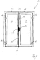
- FIG. 1 is a generally designated 10 door, which has a stationary leaf 12 and a moving wing 14. Both the inactive leaf 12 and the active leaf 14 are pivotally connected by hinges 16 to a frame 18.
- the active leaf 14 can be locked via a lock 20 with the inactive leaf 12 and the inactive leaf 12 has a floating bolt lock 22, to which an upper drive rod 24 and a lower drive rod 26 are coupled.
- the lower drive rod 26 engages with its downwardly facing free end 28 in the ground and the upper drive rod 24 engages with its upwardly facing free end 30 in the crossbar 32 of the frame 18 a.
- the lock 20 and the drive bolt lock 22 are opposite to each other, so that the latch of the lock 20 engages the drive bolt lock 22. Likewise, the latch of the lock 20 engages the drive bolt lock 22.
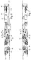
- FIGS. 2 and 3 show the drive bolt lock 22 without housing cover, wherein the drive bolt lock 22 is screwed to a cuff 34.
- a control slide 36 Inside the floating bolt lock 22 is a control slide 36 which has a one of the one end of a driving opening 38, on which the driver of a drive motor 40 engages over which the spool 36 in the longitudinal direction of the floating bolt lock 22 and parallel to the cuff 34 is displaceable.
- the spool 36 has a first cam 42 (see FIG. 8 ) With a first control section 44 and a second control section 46 for a Fallenauswerfer 48, which engages with a control pin 50 in the first control cam 42.
- the control pin 50 is guided in a transverse groove 52 in the housing base 54 such that the Fallenauswerfer 48 can move only transverse to the cuff 34.
- the spool 36 also has a second control cam 56 with a first control section 58 and a second control section 60 for a Bolt ejector 62, which engages with a control pin 64 in the second control cam 56.
- the control pin 64 is likewise guided in a transverse groove in the housing base 54 in such a manner that the bolt ejector 62 can move exclusively transversely to the cuff 34.
- Both cams 42 and 56 and in particular the two second control sections 44 and 58 each have a cutout 66, whose function will be explained later.
- the driver of the drive motor 40 is moved by a first distance 68 and thereby the spool 36 is moved to a first position.
- the two first control section 44 and 58 have the two control pins 50 and 64 of the Fallenauswerfers 48 and 60 Riegelauswerfers displaced transversely to the cuff 34 and placed the two ejectors 48 and 62 in a position in which this the latch and the latch of the lock 20 from the Eject the floating bolt lock 22.
- the leaf 14 can now be opened.
- the spool 36 also has a control slot 72, in which a pin 74 of a reversing lever 76 engages.
- the reversing lever 76 is pivotally mounted and has a first pivot arm 78, from which the pin 74 protrudes.
- the second pivot arm 80 engages behind with its hook-shaped end a driver pin 82 of a driver 84 which is displaceably mounted in the lock housing.
- a pull rod 86 is screwed, which extends to the lower end of the floating bolt lock 22 and to which a Einzugsschieber 88 is fixed for the lower drive rod 26.
- the driver 84 has a second driving pin 90, on which the hook-shaped end of a second coupling member 92 engages.
- the second coupling member 92 is pivotally mounted and forms with an extension a slot guide 94 for a pin 96 of a first rotatably mounted coupling member 98.
- the pin 96 is a sprocket portion 100 opposite, which meshes with a toothing 102 of a Nussschwenkhebels 104.
- the end of an arm 110 of a pull-in rocker 112 is coupled, which engages with an actuating finger 114 an intake slide 116.
- unactuated drive motor 40 (FIG. FIGS. 2 and 3 ) is the pin 74 at one end of the control slot 72 at.
- the pin 74 In the intermediate position of the drive motor 40 according to the FIGS. 4 and 5 the pin 74 is located at the other end of the Control slot 72, so that the lever 76 continues to assume its rest position. This means that although the trap ejector 48 and the latch ejector 62 assume their working position, the drive rods 24 and 26 are still pushed out.
- a first rotation of the pusher nut 106 in which the nut pivot lever 104 is entrained via the two lateral catches, causes a first rotation of the nut pivot lever 104 about the axis of the pusher nut 106, now serving the nut pivot lever 104 as a drive for the intake rocker, the first and second coupling member 98 and 92.
- the intake rocker 112 and the lever arm of the Nussschwenkhebels 104 form a Fallenauswerferantrieb and the two coupling members 92 and 98 a Riegelauswerferantrieb.
- the trap ejector 48 and the latch ejector 62 are ejected.
- the driving pin 82 of the driver 84 lifts off the reversing lever 76 and thereby the spool 36 is not actuated and remains in its rest position.
- a displacement of the Fallenauswerfers 48 and the Riegelauswerfers 62 can still take place, since the two control pins 50 and 64 can lift in the free punch 66 of the two control sections 44 and 58.
Landscapes
- Engineering & Computer Science (AREA)
- Mechanical Engineering (AREA)
- Physics & Mathematics (AREA)
- Electromagnetism (AREA)
- Structural Engineering (AREA)
- Lock And Its Accessories (AREA)
Claims (11)
- Serrure à crémone (22) pour une porte (10) présentant un dormant (12) et un battant (14), ayant un éjecteur de loquet (48), un coulisseau de commande (36) pouvant être déplacé parallèlement à une têtière (34) et un coulisseau d'alimentation (88, 116) pour une tige d'entraînement (24, 26), dans lequel lors de l'actionnement du coulisseau de commande (36), tout d'abord l'éjecteur de loquet (48) coulisse, puis le coulisseau d'alimentation (88, 116) est entraîné, caractérisée en ce que le coulisseau de commande (36) est couplé par l'intermédiaire d'une fente de commande (72) avec un levier d'inversion (76) au coulisseau d'alimentation (88, 116).
- Serrure à crémone selon la revendication 1, caractérisée en ce que le coulisseau de commande (36) peut être entrainé exclusivement par un moteur, en particulier peut être déplacé.
- Serrure à crémone selon la revendication 1 ou 2, caractérisée en ce que le coulisseau de commande (36) comporte une première came de commande (42) ayant des première et une seconde sections de commande (44, 46) pour l'éjecteur de loquet (48), et en ce que l'éjecteur de loquet (48) est éjecté par l'intermédiaire de la première section de commande (44), dans lequel la première section de commande (44) présente une section libre (66), par l'intermédiaire de laquelle un élément de commande (50) de l'éjecteur de loquet (48) peut se démarquer de la première section de commande (44).
- Serrure à crémone selon l'une quelconque des revendications précédentes, caractérisée en ce que le coulisseau de commande (36) comporte une seconde came de commande (56) ayant des première et seconde sections de commande (58, 60) pour un éjecteur de pêne (62), et en ce que l'éjecteur de pêne (62) est éjecté par l'intermédiaire de la première section de commande (58), dans lequel la première section de commande (58) présente une section libre (66) ; par l'intermédiaire de laquelle un élément de commande (64) de l'éjecteur de pêne (62) peut se démarquer de la première section de commande (58).
- Serrure à crémone selon la revendication 3 ou 4, caractérisée en ce que la section libre (66) est de forme triangulaire.
- Serrure à crémone selon l'une quelconque des revendications précédentes, caractérisée par un fouillot (106) et un levier pivotant de fouillot (104) pouvant être entraîné par le fouillot (106), à l'aide duquel l'éjecteur de loquet (48) peut être poussé directement ou indirectement.
- Serrure à crémone selon la revendication 6, caractérisée en ce que le levier pivotant de fouillot (104) est couplé à une bielle oscillante d'alimentation (112) pour le coulisseau d'alimentation (116) de la tige d'entraînement (24).
- Serrure à crémone selon les revendications 6 ou 7, caractérisée en ce que le levier pivotant de fouillot (104) est couplé au fouillot (106) par l'intermédiaire d'une roue libre.
- Serrure à crémone selon l'une des revendications 6 à 8, caractérisée en ce que le levier pivotant de fouillot (104) engrène avec un premier élément de couplage rotatif (98), qui pousse l'éjecteur de pêne (62).
- Serrure à crémone la revendication 9, caractérisée en ce que le premier élément de couplage (98) est couplé à un second élément de couplage (92), et en ce que le second élément de couplage (92) entraîne un coulisseau d'alimentation (88) pour une seconde tige d'entraînement (26).
- Serrure à crémone selon les revendications 7 et 10, caractérisée en ce que les premier et second éléments de couplage (98, 92), le levier pivotant de fouillot (104), la bielle oscillante d'alimentation (112) et le premier coulisseau d'alimentation (116) peuvent être actionnés au moyen du levier de renvoi (76) du second coulisseau d'alimentation (88)
Priority Applications (2)
| Application Number | Priority Date | Filing Date | Title |
|---|---|---|---|
| PL12199563T PL2749721T3 (pl) | 2012-12-28 | 2012-12-28 | Zamek baskwilowy |
| EP12199563.3A EP2749721B1 (fr) | 2012-12-28 | 2012-12-28 | Crémone espagnolette |
Applications Claiming Priority (1)
| Application Number | Priority Date | Filing Date | Title |
|---|---|---|---|
| EP12199563.3A EP2749721B1 (fr) | 2012-12-28 | 2012-12-28 | Crémone espagnolette |
Publications (2)
| Publication Number | Publication Date |
|---|---|
| EP2749721A1 EP2749721A1 (fr) | 2014-07-02 |
| EP2749721B1 true EP2749721B1 (fr) | 2016-08-24 |
Family
ID=47561249
Family Applications (1)
| Application Number | Title | Priority Date | Filing Date |
|---|---|---|---|
| EP12199563.3A Active EP2749721B1 (fr) | 2012-12-28 | 2012-12-28 | Crémone espagnolette |
Country Status (2)
| Country | Link |
|---|---|
| EP (1) | EP2749721B1 (fr) |
| PL (1) | PL2749721T3 (fr) |
Cited By (1)
| Publication number | Priority date | Publication date | Assignee | Title |
|---|---|---|---|---|
| EP3543439A1 (fr) | 2018-03-22 | 2019-09-25 | dormakaba Deutschland GmbH | Procédé pour un ensemble serrure |
Families Citing this family (2)
| Publication number | Priority date | Publication date | Assignee | Title |
|---|---|---|---|---|
| DE202015103708U1 (de) * | 2015-07-15 | 2015-08-25 | Heinrich Strenger GmbH & Co. KG | Kantriegel mit elektrischem Motor |
| DE102018106832A1 (de) * | 2018-03-22 | 2019-09-26 | Dormakaba Deutschland Gmbh | Gegenschloss für eine Standflügeltür |
Family Cites Families (3)
| Publication number | Priority date | Publication date | Assignee | Title |
|---|---|---|---|---|
| DE202006001383U1 (de) * | 2006-01-27 | 2006-04-13 | Bks Gmbh | Treibriegelschloß |
| DE202007000599U1 (de) | 2007-01-10 | 2007-03-15 | Kfv Karl Fliether Gmbh & Co. Kg | Verriegelungsbeschlag |
| DE102009025469B3 (de) | 2009-06-15 | 2011-04-14 | Bks Gmbh | Treibriegelschloss |
-
2012
- 2012-12-28 PL PL12199563T patent/PL2749721T3/pl unknown
- 2012-12-28 EP EP12199563.3A patent/EP2749721B1/fr active Active
Cited By (1)
| Publication number | Priority date | Publication date | Assignee | Title |
|---|---|---|---|---|
| EP3543439A1 (fr) | 2018-03-22 | 2019-09-25 | dormakaba Deutschland GmbH | Procédé pour un ensemble serrure |
Also Published As
| Publication number | Publication date |
|---|---|
| PL2749721T3 (pl) | 2017-02-28 |
| EP2749721A1 (fr) | 2014-07-02 |
Similar Documents
| Publication | Publication Date | Title |
|---|---|---|
| EP1932989B1 (fr) | Système de fermeture pour portes, fenêtres ou analogues, en particulier crémone-serrure à fonction d'urgence et de verrouillage à plusieurs points | |
| EP2951369B1 (fr) | Serrure anti-panique | |
| DE102006059568B4 (de) | Schließanlage für Türen, Fenster oder dergleichen, insbesondere Treibstangenschloss mit Panikfunktion und Mehrpunktverriegelung | |
| EP2264268B1 (fr) | Crémone serrure | |
| EP0798436A2 (fr) | Dispositif de verrouillage | |
| EP1574644A2 (fr) | Système de verrouillage pour portes, fenêtres ou similaires, notamment crémone-serrure avec fonction anti-panique et avec plusieurs points de condamnation | |
| EP0942135B2 (fr) | Dispositif de verrouillage | |
| EP2749721B1 (fr) | Crémone espagnolette | |
| EP3144455B1 (fr) | Dispositif de verrouillage | |
| DE202005000939U1 (de) | Verriegelungseinrichtung | |
| EP2339096B1 (fr) | Serrure à crémone dotée d'une fonction anti-panique et d'un verrouillage multiple | |
| EP1234938A2 (fr) | Crémone-serrure | |
| EP2072723A2 (fr) | Crémone-serrure | |
| EP2072725A2 (fr) | Crémone-serrure | |
| DE2738746B2 (de) | Auslösevorrichtung für ein Paniktürschloß mit Falle und Riegel | |
| DE3831529C2 (de) | Treibstangenverschluß | |
| EP1617018B1 (fr) | Serrure de porte électromécanique | |
| EP3122965B1 (fr) | Serrure anti-panique | |
| DE102008015655A1 (de) | Panikschloss | |
| EP0972900B1 (fr) | Crémone-serrure | |
| EP0974721B1 (fr) | Serrure à plusieurs pênes | |
| DE102013013547A1 (de) | Schloss mit Riegel mit Entriegelungspin | |
| EP0823521B1 (fr) | Serrure à crémone | |
| EP2320013B1 (fr) | Armature dotée d'une transmission de renvoi | |
| DE202022106561U1 (de) | Schließvorrichtung |
Legal Events
| Date | Code | Title | Description |
|---|---|---|---|
| 17P | Request for examination filed |
Effective date: 20140103 |
|
| AK | Designated contracting states |
Kind code of ref document: A1 Designated state(s): AL AT BE BG CH CY CZ DE DK EE ES FI FR GB GR HR HU IE IS IT LI LT LU LV MC MK MT NL NO PL PT RO RS SE SI SK SM TR |
|
| AX | Request for extension of the european patent |
Extension state: BA ME |
|
| PUAI | Public reference made under article 153(3) epc to a published international application that has entered the european phase |
Free format text: ORIGINAL CODE: 0009012 |
|
| GRAP | Despatch of communication of intention to grant a patent |
Free format text: ORIGINAL CODE: EPIDOSNIGR1 |
|
| RIC1 | Information provided on ipc code assigned before grant |
Ipc: E05C 9/04 20060101ALI20160226BHEP Ipc: E05C 7/04 20060101AFI20160226BHEP Ipc: E05B 47/00 20060101ALI20160226BHEP Ipc: E05B 63/24 20060101ALI20160226BHEP Ipc: E05B 65/10 20060101ALI20160226BHEP |
|
| INTG | Intention to grant announced |
Effective date: 20160318 |
|
| RIN1 | Information on inventor provided before grant (corrected) |
Inventor name: SCHOPPA, ALFRED Inventor name: VADALA, JONATHAN Inventor name: KNAPPIK, DANIEL Inventor name: HENNECKE, GERHARD |
|
| GRAS | Grant fee paid |
Free format text: ORIGINAL CODE: EPIDOSNIGR3 |
|
| GRAA | (expected) grant |
Free format text: ORIGINAL CODE: 0009210 |
|
| AK | Designated contracting states |
Kind code of ref document: B1 Designated state(s): AL AT BE BG CH CY CZ DE DK EE ES FI FR GB GR HR HU IE IS IT LI LT LU LV MC MK MT NL NO PL PT RO RS SE SI SK SM TR |
|
| REG | Reference to a national code |
Ref country code: GB Ref legal event code: FG4D Free format text: NOT ENGLISH |
|
| REG | Reference to a national code |
Ref country code: CH Ref legal event code: EP |
|
| REG | Reference to a national code |
Ref country code: AT Ref legal event code: REF Ref document number: 823272 Country of ref document: AT Kind code of ref document: T Effective date: 20160915 |
|
| REG | Reference to a national code |
Ref country code: IE Ref legal event code: FG4D Free format text: LANGUAGE OF EP DOCUMENT: GERMAN |
|
| REG | Reference to a national code |
Ref country code: CH Ref legal event code: NV Representative=s name: DREISS PATENTANWAELTE PARTG MBB, DE |
|
| REG | Reference to a national code |
Ref country code: DE Ref legal event code: R096 Ref document number: 502012008046 Country of ref document: DE |
|
| REG | Reference to a national code |
Ref country code: NL Ref legal event code: FP |
|
| REG | Reference to a national code |
Ref country code: FR Ref legal event code: PLFP Year of fee payment: 5 |
|
| REG | Reference to a national code |
Ref country code: LT Ref legal event code: MG4D |
|
| PG25 | Lapsed in a contracting state [announced via postgrant information from national office to epo] |
Ref country code: RS Free format text: LAPSE BECAUSE OF FAILURE TO SUBMIT A TRANSLATION OF THE DESCRIPTION OR TO PAY THE FEE WITHIN THE PRESCRIBED TIME-LIMIT Effective date: 20160824 Ref country code: FI Free format text: LAPSE BECAUSE OF FAILURE TO SUBMIT A TRANSLATION OF THE DESCRIPTION OR TO PAY THE FEE WITHIN THE PRESCRIBED TIME-LIMIT Effective date: 20160824 Ref country code: NO Free format text: LAPSE BECAUSE OF FAILURE TO SUBMIT A TRANSLATION OF THE DESCRIPTION OR TO PAY THE FEE WITHIN THE PRESCRIBED TIME-LIMIT Effective date: 20161124 Ref country code: HR Free format text: LAPSE BECAUSE OF FAILURE TO SUBMIT A TRANSLATION OF THE DESCRIPTION OR TO PAY THE FEE WITHIN THE PRESCRIBED TIME-LIMIT Effective date: 20160824 Ref country code: LT Free format text: LAPSE BECAUSE OF FAILURE TO SUBMIT A TRANSLATION OF THE DESCRIPTION OR TO PAY THE FEE WITHIN THE PRESCRIBED TIME-LIMIT Effective date: 20160824 |
|
| PG25 | Lapsed in a contracting state [announced via postgrant information from national office to epo] |
Ref country code: PT Free format text: LAPSE BECAUSE OF FAILURE TO SUBMIT A TRANSLATION OF THE DESCRIPTION OR TO PAY THE FEE WITHIN THE PRESCRIBED TIME-LIMIT Effective date: 20161226 Ref country code: SE Free format text: LAPSE BECAUSE OF FAILURE TO SUBMIT A TRANSLATION OF THE DESCRIPTION OR TO PAY THE FEE WITHIN THE PRESCRIBED TIME-LIMIT Effective date: 20160824 Ref country code: ES Free format text: LAPSE BECAUSE OF FAILURE TO SUBMIT A TRANSLATION OF THE DESCRIPTION OR TO PAY THE FEE WITHIN THE PRESCRIBED TIME-LIMIT Effective date: 20160824 Ref country code: GR Free format text: LAPSE BECAUSE OF FAILURE TO SUBMIT A TRANSLATION OF THE DESCRIPTION OR TO PAY THE FEE WITHIN THE PRESCRIBED TIME-LIMIT Effective date: 20161125 Ref country code: LV Free format text: LAPSE BECAUSE OF FAILURE TO SUBMIT A TRANSLATION OF THE DESCRIPTION OR TO PAY THE FEE WITHIN THE PRESCRIBED TIME-LIMIT Effective date: 20160824 |
|
| PG25 | Lapsed in a contracting state [announced via postgrant information from national office to epo] |
Ref country code: RO Free format text: LAPSE BECAUSE OF FAILURE TO SUBMIT A TRANSLATION OF THE DESCRIPTION OR TO PAY THE FEE WITHIN THE PRESCRIBED TIME-LIMIT Effective date: 20160824 Ref country code: EE Free format text: LAPSE BECAUSE OF FAILURE TO SUBMIT A TRANSLATION OF THE DESCRIPTION OR TO PAY THE FEE WITHIN THE PRESCRIBED TIME-LIMIT Effective date: 20160824 |
|
| REG | Reference to a national code |
Ref country code: DE Ref legal event code: R097 Ref document number: 502012008046 Country of ref document: DE |
|
| PG25 | Lapsed in a contracting state [announced via postgrant information from national office to epo] |
Ref country code: BG Free format text: LAPSE BECAUSE OF FAILURE TO SUBMIT A TRANSLATION OF THE DESCRIPTION OR TO PAY THE FEE WITHIN THE PRESCRIBED TIME-LIMIT Effective date: 20161124 Ref country code: SM Free format text: LAPSE BECAUSE OF FAILURE TO SUBMIT A TRANSLATION OF THE DESCRIPTION OR TO PAY THE FEE WITHIN THE PRESCRIBED TIME-LIMIT Effective date: 20160824 Ref country code: SK Free format text: LAPSE BECAUSE OF FAILURE TO SUBMIT A TRANSLATION OF THE DESCRIPTION OR TO PAY THE FEE WITHIN THE PRESCRIBED TIME-LIMIT Effective date: 20160824 Ref country code: CZ Free format text: LAPSE BECAUSE OF FAILURE TO SUBMIT A TRANSLATION OF THE DESCRIPTION OR TO PAY THE FEE WITHIN THE PRESCRIBED TIME-LIMIT Effective date: 20160824 Ref country code: DK Free format text: LAPSE BECAUSE OF FAILURE TO SUBMIT A TRANSLATION OF THE DESCRIPTION OR TO PAY THE FEE WITHIN THE PRESCRIBED TIME-LIMIT Effective date: 20160824 Ref country code: BE Free format text: LAPSE BECAUSE OF NON-PAYMENT OF DUE FEES Effective date: 20161231 |
|
| PLBE | No opposition filed within time limit |
Free format text: ORIGINAL CODE: 0009261 |
|
| STAA | Information on the status of an ep patent application or granted ep patent |
Free format text: STATUS: NO OPPOSITION FILED WITHIN TIME LIMIT |
|
| 26N | No opposition filed |
Effective date: 20170526 |
|
| GBPC | Gb: european patent ceased through non-payment of renewal fee |
Effective date: 20161228 |
|
| PG25 | Lapsed in a contracting state [announced via postgrant information from national office to epo] |
Ref country code: SI Free format text: LAPSE BECAUSE OF FAILURE TO SUBMIT A TRANSLATION OF THE DESCRIPTION OR TO PAY THE FEE WITHIN THE PRESCRIBED TIME-LIMIT Effective date: 20160824 |
|
| PG25 | Lapsed in a contracting state [announced via postgrant information from national office to epo] |
Ref country code: MC Free format text: LAPSE BECAUSE OF FAILURE TO SUBMIT A TRANSLATION OF THE DESCRIPTION OR TO PAY THE FEE WITHIN THE PRESCRIBED TIME-LIMIT Effective date: 20160824 |
|
| REG | Reference to a national code |
Ref country code: IE Ref legal event code: MM4A |
|
| PG25 | Lapsed in a contracting state [announced via postgrant information from national office to epo] |
Ref country code: LU Free format text: LAPSE BECAUSE OF NON-PAYMENT OF DUE FEES Effective date: 20161228 |
|
| PG25 | Lapsed in a contracting state [announced via postgrant information from national office to epo] |
Ref country code: GB Free format text: LAPSE BECAUSE OF NON-PAYMENT OF DUE FEES Effective date: 20161228 Ref country code: IE Free format text: LAPSE BECAUSE OF NON-PAYMENT OF DUE FEES Effective date: 20161228 |
|
| REG | Reference to a national code |
Ref country code: FR Ref legal event code: PLFP Year of fee payment: 6 |
|
| REG | Reference to a national code |
Ref country code: BE Ref legal event code: MM Effective date: 20161231 |
|
| REG | Reference to a national code |
Ref country code: DE Ref legal event code: R082 Ref document number: 502012008046 Country of ref document: DE |
|
| PG25 | Lapsed in a contracting state [announced via postgrant information from national office to epo] |
Ref country code: HU Free format text: LAPSE BECAUSE OF FAILURE TO SUBMIT A TRANSLATION OF THE DESCRIPTION OR TO PAY THE FEE WITHIN THE PRESCRIBED TIME-LIMIT; INVALID AB INITIO Effective date: 20121228 |
|
| PG25 | Lapsed in a contracting state [announced via postgrant information from national office to epo] |
Ref country code: MK Free format text: LAPSE BECAUSE OF FAILURE TO SUBMIT A TRANSLATION OF THE DESCRIPTION OR TO PAY THE FEE WITHIN THE PRESCRIBED TIME-LIMIT Effective date: 20160824 Ref country code: IS Free format text: LAPSE BECAUSE OF FAILURE TO SUBMIT A TRANSLATION OF THE DESCRIPTION OR TO PAY THE FEE WITHIN THE PRESCRIBED TIME-LIMIT Effective date: 20160824 Ref country code: CY Free format text: LAPSE BECAUSE OF FAILURE TO SUBMIT A TRANSLATION OF THE DESCRIPTION OR TO PAY THE FEE WITHIN THE PRESCRIBED TIME-LIMIT Effective date: 20160824 |
|
| PG25 | Lapsed in a contracting state [announced via postgrant information from national office to epo] |
Ref country code: MT Free format text: LAPSE BECAUSE OF FAILURE TO SUBMIT A TRANSLATION OF THE DESCRIPTION OR TO PAY THE FEE WITHIN THE PRESCRIBED TIME-LIMIT Effective date: 20160824 |
|
| PG25 | Lapsed in a contracting state [announced via postgrant information from national office to epo] |
Ref country code: AL Free format text: LAPSE BECAUSE OF FAILURE TO SUBMIT A TRANSLATION OF THE DESCRIPTION OR TO PAY THE FEE WITHIN THE PRESCRIBED TIME-LIMIT Effective date: 20160824 Ref country code: TR Free format text: LAPSE BECAUSE OF FAILURE TO SUBMIT A TRANSLATION OF THE DESCRIPTION OR TO PAY THE FEE WITHIN THE PRESCRIBED TIME-LIMIT Effective date: 20160824 |
|
| PGFP | Annual fee paid to national office [announced via postgrant information from national office to epo] |
Ref country code: CH Payment date: 20230103 Year of fee payment: 11 |
|
| P01 | Opt-out of the competence of the unified patent court (upc) registered |
Effective date: 20230509 |
|
| PGFP | Annual fee paid to national office [announced via postgrant information from national office to epo] |
Ref country code: NL Payment date: 20231220 Year of fee payment: 12 Ref country code: IT Payment date: 20231228 Year of fee payment: 12 Ref country code: FR Payment date: 20231221 Year of fee payment: 12 Ref country code: DE Payment date: 20231214 Year of fee payment: 12 Ref country code: AT Payment date: 20231221 Year of fee payment: 12 |
|
| PGFP | Annual fee paid to national office [announced via postgrant information from national office to epo] |
Ref country code: PL Payment date: 20231214 Year of fee payment: 12 |
|
| PGFP | Annual fee paid to national office [announced via postgrant information from national office to epo] |
Ref country code: CH Payment date: 20240101 Year of fee payment: 12 |