EP1574644A2 - Locking system for doors, windows or similar, in particular espagnolette lock with anti-panic function and multiple lock points - Google Patents
Locking system for doors, windows or similar, in particular espagnolette lock with anti-panic function and multiple lock points Download PDFInfo
- Publication number
- EP1574644A2 EP1574644A2 EP05000184A EP05000184A EP1574644A2 EP 1574644 A2 EP1574644 A2 EP 1574644A2 EP 05000184 A EP05000184 A EP 05000184A EP 05000184 A EP05000184 A EP 05000184A EP 1574644 A2 EP1574644 A2 EP 1574644A2
- Authority
- EP
- European Patent Office
- Prior art keywords
- lock
- bolt
- chain
- panic
- locking
- Prior art date
- Legal status (The legal status is an assumption and is not a legal conclusion. Google has not performed a legal analysis and makes no representation as to the accuracy of the status listed.)
- Withdrawn
Links
Images


Classifications
-
- E—FIXED CONSTRUCTIONS
- E05—LOCKS; KEYS; WINDOW OR DOOR FITTINGS; SAFES
- E05C—BOLTS OR FASTENING DEVICES FOR WINGS, SPECIALLY FOR DOORS OR WINDOWS
- E05C9/00—Arrangements of simultaneously actuated bolts or other securing devices at well-separated positions on the same wing
- E05C9/18—Details of fastening means or of fixed retaining means for the ends of bars
- E05C9/1825—Fastening means
- E05C9/1875—Fastening means performing pivoting movements
-
- E—FIXED CONSTRUCTIONS
- E05—LOCKS; KEYS; WINDOW OR DOOR FITTINGS; SAFES
- E05B—LOCKS; ACCESSORIES THEREFOR; HANDCUFFS
- E05B63/00—Locks or fastenings with special structural characteristics
- E05B63/16—Locks or fastenings with special structural characteristics with the handles on opposite sides moving independently
-
- E—FIXED CONSTRUCTIONS
- E05—LOCKS; KEYS; WINDOW OR DOOR FITTINGS; SAFES
- E05C—BOLTS OR FASTENING DEVICES FOR WINGS, SPECIALLY FOR DOORS OR WINDOWS
- E05C9/00—Arrangements of simultaneously actuated bolts or other securing devices at well-separated positions on the same wing
- E05C9/02—Arrangements of simultaneously actuated bolts or other securing devices at well-separated positions on the same wing with one sliding bar for fastening when moved in one direction and unfastening when moved in opposite direction; with two sliding bars moved in the same direction when fastening or unfastening
- E05C9/026—Arrangements of simultaneously actuated bolts or other securing devices at well-separated positions on the same wing with one sliding bar for fastening when moved in one direction and unfastening when moved in opposite direction; with two sliding bars moved in the same direction when fastening or unfastening comprising key-operated locks, e.g. a lock cylinder to drive auxiliary deadbolts or latch bolts
-
- E—FIXED CONSTRUCTIONS
- E05—LOCKS; KEYS; WINDOW OR DOOR FITTINGS; SAFES
- E05B—LOCKS; ACCESSORIES THEREFOR; HANDCUFFS
- E05B59/00—Locks with latches separate from the lock-bolts or with a plurality of latches or lock-bolts
-
- E—FIXED CONSTRUCTIONS
- E05—LOCKS; KEYS; WINDOW OR DOOR FITTINGS; SAFES
- E05B—LOCKS; ACCESSORIES THEREFOR; HANDCUFFS
- E05B63/00—Locks or fastenings with special structural characteristics
- E05B63/04—Locks or fastenings with special structural characteristics for alternative use on the right-hand or left-hand side of wings
-
- E—FIXED CONSTRUCTIONS
- E05—LOCKS; KEYS; WINDOW OR DOOR FITTINGS; SAFES
- E05B—LOCKS; ACCESSORIES THEREFOR; HANDCUFFS
- E05B65/00—Locks or fastenings for special use
- E05B65/10—Locks or fastenings for special use for panic or emergency doors
- E05B65/1086—Locks with panic function, e.g. allowing opening from the inside without a ley even when locked from the outside
Definitions
- the invention relates to a locking system for doors, windows or the like, in particular a espagnolette lock with panic function and multipoint locking.
- Door locks with panic function are in different embodiments known, and also for doors with multi-point locking.
- the well-known Door locks with multi-point locking and panic function become to Locking with a door key operated via a lock cylinder.
- the Panic opening, d. H. the retraction of all locking points without door key takes place from the inside of the door, by pressing a Door handle or a bar fitting.
- To open the panic lock to avoid from the outside of the door there is a regular Used fitting that does not allow the lock nut to rotate and to unlock the door lock.
- For multi-point locks with bilateral Door handles can always only the Lock latch be retracted, d. H. in the closed state is the door from the outside without door key not open.
- the invention is based on the object, a locking system for doors, Window or the like, in particular a drive rod lock with panic function and multipoint interlocking, which acted as a push-button Version by a relatively simple, functional and cheap Structure distinguishes and beyond for both doors DIN links as well also DIN-law can be used.
- the locking system according to the invention with multi-point locking and panic function is a press-operated embodiment.
- the multipoint interlock consists of the central castle and others on a common cuff attached additional locks that are operated via the drive rods. These rods are located behind the cuff and are by the moved multipart lock nut, and thereby drive the additional locks at.
- the central lock has next to the lock latch a central latch and the as it were four-part castle nut.
- the Schlossnusshziern be over the Handle bolt coupled to the door handle.
- the central castle can be over the lock cylinder - regularly in the embodiment of a profile cylinder - block against unauthorized opening from the outside. From the inside of the door All locking points can be accessed at any time without a door key simply pressing the door handle and thus pressing the longer one Be retracted pusher bolt. Due to the special structure of the four-part Lock nut with the two halves of the lock nut, the panic catcher and the chain link, and taking into account the two associated different-length pusher bolts, a pusher actuated panic multipoint locking created for both doors DIN links as well DIN-law can be used.
- Panic function On which side of the castle are the Panic function is to be located by the fitter by the optional plugging set the handle bolt.
- the longer handle bolt operates basically the panic catcher and defines the inside of the door. Except for yourself Known implementation of the latch need no further changes to be made on the locking system.
- the first half of the lock nut and / or the second half of the half lock nut can be two on a turning circle offset by a predetermined angle of rotation driving arms have, between which in each case a driving cam of Kettenmit supplementss protruding, wherein between the first half of the lock nut and the Kettenmit choir a clearance of 40 ° to 50 °, preferably 45 ° is formed.
- the Panikmit resumes the movement of the associated Driving cam of the chain drive with predetermined Motion play penetrated opening on, so that the chain catcher can also be taken from the Schlossnusshsisted, the is on the side of the panic taker.
- the Panikmit resumes partially in a bed-like depression of Kettenmit demands be stored.
- the chain driver preferably has a fork-shaped Recording for an actuating cam on the lock chain or on a assigned chain lever on the lock chain, so that the operation of the Kettenmit interventions on one or the other handle bolt on the Lock chain is transmitted and thereby actuation of the central bolt and the drive rods and consequently the additional locks in the closed position or open position.
- the panic driver has a bolt receptacle for a longer multi-edge end, z. B. square end, the longer Pusher bolt, wherein the bolt receptacle 40 ° to 50 °, preferably 45 ° free-ratchet for the longer handle bolt.
- the handle bolts preferably have a multi-edge limiting collar, z. B.
- a lock washer or the like are of a on the Surrounding collar seated compression spring, which against the inside of the Door shield presses, in the installed state, the wandering of the Handle bolts from the lock nut or their associated locknut halves to prevent.
- the collar also limits as it were Stop element the penetration depth of the handle bolts into the locknut halves.
- the shorter handle bolt is always inserted from the outside of the door. about he can only use the lock nut when not locked or when not locked locking system are actuated.
- the insertion side of the longer Handle bolt defines the panic side of the locking system, as in a Handle operation via this longer handle bolt the locking system also in the locked state and consequently with locked locking system, the over Lock cylinder has been completed, can be opened at any time.
- the invention provides that the two SchlossnusshCAn back (On the side facing away from the lock nut chain) Formations or approaches have, the fall side of at least one common spring-loaded Return plunger and on the opposite side separated from each act on its own spring-loaded return ram, to allow a separate provision of the two Schlossnusshbuln.
- the panic transmission lever is pivotally mounted and works on one Locking cams on the inner latch below the pivot axis of this inner latch.
- a spring-loaded on or in the inner latch Guard on the lock cylinder side facing out, the one having a control cam cooperating control pin and of a driving lug of the lock cylinder is actuated.
- the multipoint interlock consists of a central lock 1 and more a common cuff 2 attached additional interlocks 3, the behind the cuff 2 arranged drive rods 4 are operated.
- the additional locks 3 have according to the embodiment of the pivot bolt, it But also bolt bolts can be used.
- the locking system has a Handle-operated and key-operated central lock 1 with a spring-loadable Lock latch 5, also with a central latch 6, a multi-part Locknut 7 and a lock cylinder 8, designed as a profile cylinder can be.
- the lock nut 7 works on a lock chain 9 on the Central bar 6 and on the auxiliary locking 3 actuated drive rods 4.
- first lock nut half 10 and a second Locknut half 11 are a Kettenmit counseling 12 and a panic cam 13th coaxially arranged to form the lock nut.
- the chain driver 12 interacts with the lock chain 9, the Panikmit disturbing 13 acts with a Panic translation lever 14 together.
- the first half-castle nut 10 is a longer handle bolt 15 can be used, the panic driver when pressed 13 and the chain cam 12 with a predetermined clearance entraining.
- second Schlossnusshayne 11 is a shorter pusher bolt sixteenth used, which the associated Kettenmit repertoire 12 with predetermined Clearance can operate.
- a pivotally mounted inner bar 17th provided by means of the lock cylinder 8 in a lock chain 9 at extended central latch 6 and located in the locked position Additional locking 3 blocking dead center position T is adjustable.
- the Panic translation lever 14 interacts with the inner latch 17 at the door inner side Handle operation of the longer handle bolt 15 in the lock-opening sense together.
- the first half lock nut 10 and the second half lock nut 11 have two on an indicated turning circle to a predetermined Angle of rotation offset driver arms 18, 19 and 20, 21, between which each a drive cam 22, 23 of the chain cam 12 projects, wherein between the first half-lock nut 10 and the chain cam 12 a Clearance of 45 ° is formed.
- the panic cam 13 has one of the associated drive cam 22 of the Kettenmit demandss 12 with predetermined Motion play penetrated opening 24 and is partial stored in a bed-like recess 25 of the Kettenmit demandss 12.
- the Kettenmit nutrition 12 has a fork-shaped receptacle 26 for a Actuating cam 27 on the lock chain 9 or an associated Chain lever of the lock chain.
- the panic cam 13 has one on one Control cam 28 on the pivotally mounted panic transmission lever 14th working control pin 29.
- the panic cam 13 has a bolt receptacle for a longer multi-edge end 30, z. B.
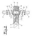
- the handle bolts 15, 16 each have their multi-edge ends 30, 32nd limiting collar 34, 35, z. B. a lock washer and are of a standing on the lock washer compression spring 36, 37 surrounded.
- the both lock nut halves 10, 11 have the back of the lock chain. 9 side facing away from projections 38, 39 and approaches on the fall side of at least one spring-loaded return ram 40 and on the opposite Page separated from each own spring-loaded Return plunger 41, 42 are acted upon.
- the pivotally mounted panic transmission lever 14 is against a locking cam 43 on the inner bar 17th below the pivot axis 44 of the inner bolt 17 for its actuation pivotable.
- Fig. 2 is the longer handle bolt 15 with the longer Multi-edge end 30 in the first lock nut half 10 and the shorter handle bolt 16 with the shorter polygonal end 32 in the second end nut half 11.
- the lock latch 5 is spring-loaded.
- Fig. 3 the first half of the lock nut 10 by pushing the longer handle bolt 15 turned counterclockwise by 45 °. This will be the chain driver 12 and the Panikmit recruiting 13 rotated.
- the control pin 29 of the Panikmit ceremonies 13 pivots the Paniküber GmbHshebel 14 in Clockwise.
- the lock chain 9 is about 12 by the Kettenmit researching 20 mm downwards. As a result, the additional locking 3 and the central bolt 6 extended in the locked position.
- the second Locknut half 11 does not turn.
- Control pin 47 provides in conjunction with the associated control cam 46 in Lock case 49 that the inner latch 17 is not unintentional the locking position can move to an open position.
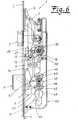
- Fig. 6 dives the shorter pusher bolt 16 with its shorter polygonal end 32 only in the second locknut half 11 a.
- the Lock chain 9 can be moved by about 3 mm in the opening direction.
- the second half-castle nut 11 can not be rotated because of Inner latch 17, the lock chain 9 and thus also the Kettenmit diversity 12th locks.
- An opening of the door lock is by the outside used shorter handle bolt 11 not possible.
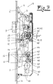
- the first castle nut half 10 remains during the opening attempt spring force in their Starting position stand. Nor does the Panikmit choir 13 rotates. - As shown in FIG. 7, the longer multi-edge end 30 of the longer pusher pin emerges 15 on the inside of the door in the locknut 7 a. It will be Both the first half of the castle nut 10 and the center housed in the nut package Panic driver 13 penetrated by the longer multi-edge end 30.
- the pre-locked panic multipoint lock is secured against opening attempts from the outside; during an opening attempt from the outside of the door, the door handle is locked and can not be pressed down; by turning the door key or lock cylinder 8 in the opening direction, the blocking position of the panic multipoint locking is canceled again; by pressing down the door handle or pusher bolt both the additional latches 3 and the central latch 6 and the latch 5 are retracted.
- the door can be opened.
Landscapes
- Engineering & Computer Science (AREA)
- Mechanical Engineering (AREA)
- Structural Engineering (AREA)
- Lock And Its Accessories (AREA)
Abstract
Es handelt sich um ein Türschloss mit Panikfunktion und Mehrpunktverriegelung, welches drücker- und schlüsselbetätigbar ist. Zwischen einer ersten Schlossnusshälfte und einer zweiten Schlossnusshälfte sind ein Kettenmitnehmer und ein Panikmitnehmer angeordnet. Der Kettenmitnehmer arbeitet auf eine Schlosskette und der Panikmitnehmer auf einen Panikübersetzungshebel, wobei in die Schlossnusshälften unterschiedlich lange Drückerbolzen einsetzbar sind und umsteckbar sind. Der längere der beiden Drückerbolzen definiert die Türinnenseite, weil er von beiden Türseiten her bis in den Panikmitnehmer eindringt. Folglich lässt sich die Schließanlage sowohl für Türen DIN-Links als auch Türen DIN-Rechts verwenden. Ein Innenriegel ist mittels des Schließzylinders in eine die Schlosskette bei ausgefahrenem Zentralriegel und in Verriegelungsstellung befindlichen Zusatzverriegelungen blockierende Totpunktstellung verstellbar. Der Panikübersetzungshebel wirkt mit dem Innenriegel bei Drückerbetätigung des längeren Drückerbolzens auf der Türinnenseite in schlossöffnendem Sinne zusammen.It is a door lock with panic function and multipoint locking, which can be pressed and key operated. Between a first half of the lock nut and a second half of the lock nut, a chain driver and a panic driver are arranged. The chain driver works on a lock chain and the Panikmitnehmer on a Panikübersetzungshebel, wherein in the lock nut halves different length handle bolts are used and can be re-plugged. The longer of the two handle bolts defines the inside of the door because it penetrates from both sides of the door into the panic driver. Consequently, the locking system can be used for both DIN-left doors and DIN-right doors. An inner latch is adjustable by means of the lock cylinder in a lock chain blocking the dead center position when the central bolt is extended and in the locking position. The Panikübersetzungshebel cooperates with the inner latch when lever handle operation of the longer handle bolt on the inside of the door in a lock-opening sense.
Description
Die Erfindung betrifft eine Schließanlage für Türen, Fenster oder dergleichen, insbesondere ein Treibstangenschloss mit Panikfunktion und Mehrpunktverriegelung.The invention relates to a locking system for doors, windows or the like, in particular a espagnolette lock with panic function and multipoint locking.
Türschlösser mit Panikfunktion sind in verschiedenen Ausführungsformen bekannt, und zwar auch für Türen mit Mehrpunktverriegelung. Die bekannten Türschlösser mit Mehrpunktverriegelung und Panikfunktion werden zum Verriegeln mit einem Türschlüssel über einen Schließzylinder betätigt. Die Paniköffnung, d. h. das Einfahren sämtlicher Verriegelungspunkte ohne Türschlüssel erfolgt von der Türinnenseite her, und zwar durch Betätigen eines Türdrückers oder eines Stangenbeschlages . Um ein Öffnen des Panikverschlusses von der Türaußenseite her zu vermeiden, wird dort regelmäßig ein Beschlag eingesetzt, der es nicht ermöglicht, die Schlossnuss zu drehen und damit das Türschloss zu entriegeln. Bei Mehrpunktverriegelungen mit beidseitigen Türdrückern kann durch den außen liegenden Türdrücker stets nur die Schlossfalle eingezogen werden, d. h. in abgeschlossenem Zustand ist die Tür von der Außenseite her ohne Türschlüssel nicht zu öffnen.Door locks with panic function are in different embodiments known, and also for doors with multi-point locking. The well-known Door locks with multi-point locking and panic function become to Locking with a door key operated via a lock cylinder. The Panic opening, d. H. the retraction of all locking points without door key takes place from the inside of the door, by pressing a Door handle or a bar fitting. To open the panic lock to avoid from the outside of the door, there is a regular Used fitting that does not allow the lock nut to rotate and to unlock the door lock. For multi-point locks with bilateral Door handles can always only the Lock latch be retracted, d. H. in the closed state is the door from the outside without door key not open.
Bei den bekannten Ausführungsformen ist die Schlossseite mit der Panikfunktion durch die Türmontage unverändert festgelegt. Folglich müssen Türen mit Türschlössern für DIN-Links oder DIN-Rechts getrennt hergestellt und auf Bestellung geliefert werden. Hierdurch entstehen zunächst einmal dem Schlosshersteller Kosten durch die Einrichtung zwei verschiedener Schlosstypen. Die Verarbeiter haben den Nachteil, dass ihnen durch die Bevorratung beider Schlossausführungen zusätzliche Kosten für die doppelte Lagerhaltung entstehen. - Unabhängig davon sind Mehrpunktverriegelungen, die zum Verriegeln über den Türschlüssel/Schließzylinder betätigt werden müssen, häufig unpopulär. Bevorzugt werden häufig ausschließlich drückerbetätigte Mehrpunktverriegelungen. Bei diesen erfolgt das Ausfahren der Verriegelungspunkte durch das Hochziehen des Türdrückers. Zum Sichern des vorverriegelten Zustands wird der Mittenriegel eintourig in Sperrstellung ausgeschlossen. Bei derartigen Ausführungsformen fehlt im Allgemeinen die Panikfunktion. Die schlüsselbetätigten Versionen mit Mehrpunktverriegelung und Panikfunktion sind aufgrund insbesondere ihrer Übersetzungsgetriebe verhältnismäßig kostenintensiv, jedenfalls wesentlich teurer in ihrer Herstellung und Anschaffung als die vergleichsweise einfach aufgebauten, drückerbetätigten Versionen.In the known embodiments, the lock side with the panic function fixed unchanged by the door assembly. Consequently, doors have to with door locks for DIN left or DIN right separately manufactured and on Order to be delivered. This initially arises once the Locksmith costs by setting up two different lock types. The processors have the disadvantage of stocking them up Both lock versions additional costs for double storage arise. - Regardless, multipoint interlocks are required for Locking must be operated via the door key / lock cylinder, often unpopular. Preference is often given only handle-operated Multipoint locks. In these, the extension of the Locking points by pulling up the door handle. To save the pre-locked state, the center bar is one-way locked in locked position. In such embodiments, the panic function is generally absent. The key operated versions with multipoint interlock and Panic function are relatively due to particular their transmission gear costly, at least much more expensive in their production and Acquisition as the comparatively simply constructed, press-operated Versions.
Der Erfindung liegt die Aufgabe zugrunde, eine Schließanlage für Türen, Fenster oder dergleichen, insbesondere ein Treibstangenschloss mit Panikfunktion und Mehrpunktverriegelung, zu schaffen, die sich als drückerbetätigte Version durch einen verhältnismäßig einfachen, funktionsgerechten und preiswerten Aufbau auszeichnet und darüber hinaus sowohl für Türen DIN-Links als auch DIN-Rechts verwendet werden kann.The invention is based on the object, a locking system for doors, Window or the like, in particular a drive rod lock with panic function and multipoint interlocking, which acted as a push-button Version by a relatively simple, functional and cheap Structure distinguishes and beyond for both doors DIN links as well also DIN-law can be used.
Zur Lösung dieser Aufgabe ist Gegenstand der Erfindung eineTo solve this problem is the subject of the invention
Schließanlage für Türen, Fenster oder dergleichen, insbesondere ein Treibstangenschloss mit Panikfunktion und Mehrpunktverriegelung, mit einem drücker- und schlüsselbetätigbaren Zentralschloss mit Schlossfalle, Zentralriegel, Schlossnuss und Schließzylinder, wobei
- die Schlossnuss über eine Schlosskette auf den Zentralriegel und Zusatzverriegelungen betätigende Treibstangen arbeitet,
- zwischen einer ersten Schlossnusshälfte und einer zweiten Schlossnusshälfte ein Kettenmitnehmer und ein Panikmitnehmer (unter Bildung der Schlossnuss) koaxial angeordnet sind,
- der Kettenmitnehmer mit der Schlosskette und der Panikmitnehmer mit einem Panikübersetzungshebel zusammenwirken,
- ein längerer Drückerbolzen in die erste Schlossnusshälfte (oder zweite Schlossnusshälfte) einsetzbar ist und bei Betätigung den Panikmitnehmer sowie den Kettenmitnehmer mit vorgegebenem Freigang mitnimmt,
- ein kürzerer Drückerbolzen in die zweite Schlossnusshälfte (oder erste Schlossnusshälfte) einsetzbar ist, welche den zugeordneten Kettenmitnehmer mit vorgegebenem Freigang betätigt,
- ein schwenkbar gelagerter Innenriegel mittels des Schließzylinders in eine die Schlosskette bei ausgefahrenem Zentralriegel und in Verriegelungsstellung befindlichen Zusatzverriegelungen blockierende Totpunktstellung verstellbar ist und
- der Panikübersetzungshebel mit dem Innenriegel bei (türinnenseitiger) Drückerbetätigung des längeren Drückerbolzens in schlossöffnendem Sinne zusammenwirkt.
- the lock nut works via a lock chain on the central bolt and additional locking actuated connecting rods,
- a chain driver and a panic driver (to form the lock nut) are arranged coaxially between a first half of the lock nut and a second half of the lock nut,
- the chain driver interacts with the lock chain and the panic driver with a panic transmission lever,
- a longer handle bolt can be inserted into the first half of the lock nut (or second half of the lock nut) and, on actuation, takes along the panic catch and the chain catch with a predetermined clearance,
- a shorter pusher bolt can be inserted into the second half of the lock nut (or first half of the lock nut), which actuates the associated chain catch with a predetermined clearance,
- a pivotally mounted inner latch is adjustable by means of the lock cylinder in a lock chain blocking the dead center position when the central bolt is extended and in the locking position
- the Panikübersetzungshebel cooperates with the inner latch in (door inner side) handle operation of the longer pusher bolt in the lock-opening sense.
Die erfindungsgemäße Schließanlage mit Mehrpunktverriegelung und Panikfunktion ist eine drückerbetätigte Ausführungsform. Die Mehrpunktverriegelung besteht aus dem Zentralschloss und weiteren an einer gemeinsamen Stulpe angebrachten Zusatzverriegelungen, die über die Treibstangen betätigt werden. Diese Treibstangen befinden sich hinter der Stulpe und werden durch die mehrteilige Schlossnuss bewegt, und treiben dadurch die Zusatzverriegelungen an. The locking system according to the invention with multi-point locking and panic function is a press-operated embodiment. The multipoint interlock consists of the central castle and others on a common cuff attached additional locks that are operated via the drive rods. These rods are located behind the cuff and are by the moved multipart lock nut, and thereby drive the additional locks at.
Das Zentralschloss besitzt neben der Schlossfalle einen Zentralriegel und die gleichsam vierteilige Schlossnuss. Die Schlossnusshälften werden über die Drückerbolzen mit dem Türdrücker gekoppelt. Das Zentralschloss lässt sich über den Schließzylinder - regelmäßig in der Ausführungsform eines Profilzylinders - gegen unbefugtes Öffnen von außen sperren. Von der Türinnenseite her können sämtliche Verriegelungspunkte jederzeit ohne Türschlüssel durch einfaches Drücken des Türdrückers und folglich Betätigen des längeren Drückerbolzens eingezogen werden. Durch den besonderen Aufbau der vierteiligen Schlossnuss mit den beiden Schlossnusshälften, dem Panikmitnehmer und dem Kettenmitnehmer, sowie unter Berücksichtigung der beiden zugehörigen unterschiedlich langen Drückerbolzen, wird eine drückerbetätigte Panik-Mehrpunktverriegelung geschaffen, die sowohl für Türen DIN-Links als auch DIN-Rechts verwendet werden können. Auf welcher Schlossseite sich die Panikfunktion befinden soll, wird vom Monteur durch das wahlweise Einstecken der Drückerbolzen festgelegt. Der längere Drückerbolzen betätigt grundsätzlich den Panikmitnehmer und definiert die Türinnenseite. Außer dem an sich bekannten Umsetzen der Schlossfalle brauchen keine weiteren Umstellungen an der Schließanlage vorgenommen zu werden.The central lock has next to the lock latch a central latch and the as it were four-part castle nut. The Schlossnusshälften be over the Handle bolt coupled to the door handle. The central castle can be over the lock cylinder - regularly in the embodiment of a profile cylinder - block against unauthorized opening from the outside. From the inside of the door All locking points can be accessed at any time without a door key simply pressing the door handle and thus pressing the longer one Be retracted pusher bolt. Due to the special structure of the four-part Lock nut with the two halves of the lock nut, the panic catcher and the chain link, and taking into account the two associated different-length pusher bolts, a pusher actuated panic multipoint locking created for both doors DIN links as well DIN-law can be used. On which side of the castle are the Panic function is to be located by the fitter by the optional plugging set the handle bolt. The longer handle bolt operates basically the panic catcher and defines the inside of the door. Except for yourself Known implementation of the latch need no further changes to be made on the locking system.
Weitere erfindungswesentliche Maßnahmen sind im Folgenden aufgeführt. So
kann die erste Schlossnusshälfte und/oder die zweite Schlossnusshälfte zwei
auf einem Drehkreis um einen vorgegebenen Drehwinkel versetzte Mitnehmerarme
aufweisen, zwischen denen jeweils ein Mitnehmernocken des Kettenmitnehmers
vorkragt, wobei zwischen der ersten Schlossnusshälfte und dem
Kettenmitnehmer ein Freigang von 40° bis 50°, vorzugsweise 45° gebildet ist.
Dadurch besteht die Möglichkeit, dass der Kettenmitnehmer nach seiner
Betätigung in seiner eingenommenen Stellung stehen bleibt, während die
Schlossnusshälften federkraftbeaufschlagt in ihre Ausgangsstellung zurückdrehen.
Zweckmäßigerweise weist der Panikmitnehmer eine von dem zugeordneten
Mitnehmernocken des Kettenmitnehmers mit vorgegebenem
Bewegungsspiel durchdrungene Durchbrechung auf, so dass der Kettenmitnehmer
auch von der Schlossnusshälfte mitgenommen werden kann, die
sich auf der Seite des Panikmitnehmers befindet. Darüber hinaus kann der
Panikmitnehmer teilweise in einer bettartigen Vertiefung des Kettenmitnehmers
gelagert sein. Der Kettenmitnehmer weist vorzugsweise eine gabelförmige
Aufnahme für einen Betätigungsnocken an der Schlosskette bzw. an einem
zugeordneten Kettenhebel der Schlosskette auf, so dass die Betätigung des
Kettenmitnehmers über den einen oder anderen Drückerbolzen auf die
Schlosskette übertragen wird und dadurch eine Betätigung des Zentralriegels
sowie der Treibstangen und folglich der Zusatzverriegelungen in Schließstellung
oder Offenstellung erfolgt. Auch die Umkehrung ist denkbar, wonach
also der Kettenmitnehmer einen Betätigungsnocken und die Schlosskette eine
gabelförmige Aufnahme für den Betätigungsnocken aufweist. - Weiter sieht die
Erfindung vor, dass der Panikmitnehmer einen auf eine Steuerkurve an dem
schwenkbar gelagerten Panikübersetzungshebel arbeitenden Steuerzapfen
aufweist. Auch in diesem Fall ist die Umkehrung möglich. In beiden Fällen wird
der Panikübersetzungshebel im Uhrzeigersinn oder gegen Uhrzeigersinn
verschwenkt. Erfindungsgemäß weist der Panikmitnehmer eine Bolzenaufnahme
für ein längeres Mehrkantende, z. B. Vierkantende, am längeren
Drückerbolzen auf, wobei die Bolzenaufnahme ein 40° bis 50°, vorzugsweise
45°-Freigang-Gesperre für den längeren Drückerbolzen besitzt. Aufgrund des
längeren Mehrkantendes greift der längere Drückerbolzen grundsätzlich in die
Bolzenaufnahme des Panikmitnehmers ein, also gleichgültig, ob der längere
Drückerbolzen von der einen Türseite her oder von der anderen Türseite her in
die Schlossnuss eingesteckt wird, so dass jene Türseite die Türinnenseite ist,
auf der sich der längere Drückerbolzen befindet und die Auslösung der Panikfunktion
ermöglicht. Daraus resultiert im Übrigen auch die Verwendungsmöglichkeit
der erfindungsgemäßen Schließanlage bzw. einer damit ausgerüsteten
Tür als Tür DIN-Links oder Tür DIN-Rechts. Folglich ist der längere
Drückerbolzen mit seinem längeren Mehrkantende auch in die zweite Schlossnusshälfte
und der kürzere Drückerbolzen mit einem kürzeren Mehrkantende,
z. B. Vierkantende, in die erste Schlossnusshälfte einsetzbar, wobei das
längere Mehrkantende des längeren Drückerbolzens mitnahmefrei bzw. mit
vorgegebenem Bewegungsspiel durch eine Durchbrechung des
Kettenmitnehmers hindurch in das Freigang-Gesperre des Panikmitnehmers zu
seiner Betätigung eindringt. Das 45°-Freigang-Gesperre sorgt dafür, dass der
Panikmitnehmer nach der Betätigung durch den längeren Drückerbolzen in
seiner eingenommenen Stellung stehen bleibt, während die Schlossnusshälften
federkraftbeaufschlagt in die Ausgangsstellung zurückdrehen. Durch ein
Verdrehen des Panikmitnehmers kann die Sperrstellung der verriegelten
Schließanlage auch ohne Türschlüssel aufgehoben werden, gleichgültig auf
welcher Türseite sich der längere Drückerbolzen befindet. Die Drückerbolzen
weisen vorzugsweise einen ihre Mehrkantenden begrenzenden Kragen, z. B.
eine Sicherungsscheibe oder dergleichen auf und sind von einer auf dem
Kragen aufsitzenden Druckfeder umgeben, welche gegen die Innenseite des
Türschildes drückt, um im eingebauten Zustand das Herauswandern der
Drückerbolzen aus der Schlossnuss bzw. den ihnen zugeordneten Schlossnusshälften
zu verhindern. Der Kragen begrenzt darüber hinaus als gleichsam
Anschlagelement die Eindringtiefe der Drückerbolzen in die Schlossnusshälften.
Der kürzere Drückerbolzen wird stets von der Türaußenseite eingesteckt. Über
ihn kann die Schlossnuss nur im nicht gesperrten Zustand bzw. bei nicht
verriegelter Schließanlage betätigt werden. Die Einsteckseite des längeren
Drückerbolzens definiert die Panikseite der Schließanlage, da bei einer
Drückerbetätigung über diesen längeren Drückerbolzen die Schließanlage auch
im gesperrten Zustand und folglich bei verriegelter Schließanlage, die über den
Schließzylinder abgeschlossen worden ist, jederzeit geöffnet werden kann.Other inventive measures are listed below. So
The first half of the lock nut and / or the second half of the half lock nut can be two
on a turning circle offset by a predetermined angle of rotation driving arms
have, between which in each case a driving cam of Kettenmitnehmers
protruding, wherein between the first half of the lock nut and the
Kettenmitnehmer a clearance of 40 ° to 50 °, preferably 45 ° is formed.
There is a possibility that the chain driver after his
Operation in its assumed position stops while the
Turn the locknut halves back to their original position with the spring force applied.
Appropriately, the Panikmitnehmer one of the associated
Driving cam of the chain drive with predetermined
Motion play penetrated opening on, so that the chain catcher
can also be taken from the Schlossnusshälfte, the
is on the side of the panic taker. In addition, the
Panikmitnehmer partially in a bed-like depression of Kettenmitnehmers
be stored. The chain driver preferably has a fork-shaped
Recording for an actuating cam on the lock chain or on a
assigned chain lever on the lock chain, so that the operation of the
Kettenmitnehmers on one or the other handle bolt on the
Lock chain is transmitted and thereby actuation of the central bolt
and the drive rods and consequently the additional locks in the closed position
or open position. The reversal is conceivable, after which
So the Kettenmitnehmer an actuating cam and the lock chain a
having fork-shaped receptacle for the actuating cam. - Next sees the
Invention that the Panikmitnehmer a on a cam on the
pivotally mounted panic gear lever operating control pin
having. Also in this case the reversal is possible. In both cases will
the panic transmission lever clockwise or counterclockwise
pivoted. According to the invention, the panic driver has a bolt receptacle
for a longer multi-edge end, z. B. square end, the longer
Pusher bolt, wherein the
Weiter sieht die Erfindung vor, dass die beiden Schlossnusshälften rückseitig (auf der der Schlossnusskette abgewandten Seite) Anformungen bzw. Ansätze aufweisen, die fallenseitig von zumindest einem gemeinsamen federbeaufschlagten Rückstellstößel und auf der gegenüberliegenden Seite getrennt von jeweils einem eigenen federbeaufschlagten Rückstellstößel beaufschlagt sind, um eine getrennte Rückstellung der beiden Schlossnusshälften zu ermöglichen. Der Panikübersetzungshebel ist schwenkbar gelagert und arbeitet auf einen Riegelnocken am Innenriegel unterhalb der Schwenkachse dieses Innenriegels. Zweckmäßigerweise ist an oder in dem Innenriegel eine federbeaufschlagte Zuhaltung auf der dem Schließzylinder zugewandten Seite geführt, die einen mit einer Steuerkurve zusammenwirkenden Steuerzapfen aufweist und von einer Mitnehmernase des Schließzylinders betätigbar ist. Dabei kann die Zuhaltung eine der Mitnehmernase des Schließzylinders zugeordnete V-förmige Lauffläche oder Gleitfläche aufweisen und steht gegenüber dem Innenriegel vor. - Die Sperrung der zuvor über einen Türdrücker vorverriegelten Stellung erfolgt über eine Schlüsselumdrehung des Schließzylinders. Dadurch wird der Innenriegel in eine eine Totpunktstellung erzeugende Position zur Schlosskette hin eingeschwenkt. Die im Innenriegel geführte und durch Federkraft beaufschlagte Zuhaltung positioniert sich in ihren beiden Endstellungen durch die im Schlosskasten eingebrachte Steuerkurve. Die Steuerkurve ist so ausgelegt, dass sich der Innenriegel nicht unbeabsichtigt aus seinen beiden Endstellungen heraus verlagern kann. Lediglich durch die Verschwenkung des Panikmitnehmers können über den Panikübersetzungshebel der Innenriegel und die Zuhaltung aus der Sperrstellung in Öffnungsstellung verlagert werden. Um sicherzustellen, dass die Mitnehmernase des Schließzylinders stets weit genug aus dem Transportbereich des Innenriegels herausgedrückt wird, ist die untere Gleitfläche der Zuhaltung V-förmig gestaltet und die Zuhaltung gegenüber dem Innenriegel vorstehend ausgebildet.Next, the invention provides that the two Schlossnusshälften back (On the side facing away from the lock nut chain) Formations or approaches have, the fall side of at least one common spring-loaded Return plunger and on the opposite side separated from each act on its own spring-loaded return ram, to allow a separate provision of the two Schlossnusshälften. The panic transmission lever is pivotally mounted and works on one Locking cams on the inner latch below the pivot axis of this inner latch. Conveniently, a spring-loaded on or in the inner latch Guard on the lock cylinder side facing out, the one having a control cam cooperating control pin and of a driving lug of the lock cylinder is actuated. It can the Guard locking one of the driving lug of the lock cylinder associated V-shaped Have running surface or sliding surface and is opposite the inner bar in front. - The blocking of the previously pre-locked by a lever handle position via a key turn of the lock cylinder. This will be the Internal latch in a dead center position generating position to the lock chain turned in. The guided in the inner bar and by spring force applied tumbler positions itself in its two end positions the control cam inserted in the lock case. The cam is like that designed so that the inner bolt does not accidentally out of its two Shift out end positions. Only by the pivoting of the Panic driver can via the Panikübersetzungshebel the inner latch and the tumbler are moved from the locked position to the open position. To ensure that the cam lug of the lock cylinder is always far enough is pushed out of the transport area of the inner bar is the lower sliding surface of the tumbler designed V-shaped and facing the tumbler formed protruding the inner bar.
Im Folgenden wird die Erfindung anhand einer lediglich ein Ausführungsbeispiel darstellenden Zeichnung näher erläutert. Es zeigen:
- Fig. 1
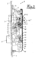
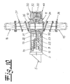
- ein Treibstangenschloss mit Panikfunktion und Mehrpunktverriegelung in schematischer Seitenansicht,
- Fig. 2
- einen Ausschnitt aus dem Gegenstand nach Fig. 1 im Bereich des Zentralschlosses mit abgenommenem Schlossdeckel und in der Grundstellung "offen",
- Fig. 3
- den Gegenstand nach Fig. 2 in der Stellung "Verriegeln von innen",
- Fig. 4
- den Gegenstand nach Fig. 3 in der Stellung "Drücker loslassen",
- Fig. 5
- den Gegenstand nach Fig. 4 in der Stellung "Schließzylinder abschließen",
- Fig. 6
- den Gegenstand nach Fig. 5 in der Stellung "Öffnungsversuch von außen",
- Fig. 7
- den Gegenstand nach Fig. 6 in der Stellung "Panikbetätigung von innen (4°)",
- Fig. 8
- den Gegenstand nach Fig. 7 in der Stellung "Panikbetätigung von innen (45°)",
- Fig. 9
- einen Querschnitt durch den Schlossnussbereich,
- Fig. 10
- den Gegenstand nach Fig. 9 mit umgesetzten Drückerbolzen,
- Fig. 11
- die Drückerbolzen für den Gegenstand nach Fig. 9,
- Fig. 12
- die mehrteilige Schlossnuss für den Gegenstand nach Fig. 9 in Explosivdarstellung,
- Fig. 13
- eine Draufsicht auf die zweite Schlossnusshälfte,
- Fig. 14
- eine Draufsicht auf die Schlossnuss mit Panikübersetzungshebel, Innenriegel und teilweise Schlossnusskette,
- Fig. 15
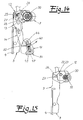
- eine Draufsicht auf den Kettenmitnehmer nach Fig. 12 mit eingestecktem längeren Mehrkantende des längeren Drückerbolzens,
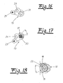
- Fig. 16
- eine Draufsicht auf den Panikmitnehmer nach Fig. 12,
- Fig. 17
- den Gegenstand nach Fig. 16 mit eingestecktem längeren Mehrkantende
des längeren Drückerbolzens im Zuge einer
Verschwenkung des Panikmitnehmers und Rückstellung des
Drückerbolzens unter Berücksichtigung eines
Freigangs von 45°, - Fig. 18
- eine Draufsicht auf die erste Schlossnusshälfte nach Fig. 12 mit darunter angedeutetem Kettenmitnehmer und 45°-Freigang.
- Fig. 1
- a espagnolette lock with panic function and multipoint locking in a schematic side view,
- Fig. 2
- a detail of the article according to FIG. 1 in the region of the central lock with the lock lid removed and in the basic position "open",
- Fig. 3
- the object according to FIG. 2 in the position "locking from inside",
- Fig. 4
- the object according to FIG. 3 in the position "release pusher",
- Fig. 5
- the object according to FIG. 4 in the position "lock cylinder",
- Fig. 6
- the article according to FIG. 5 in the position "opening attempt from outside",
- Fig. 7
- the object according to FIG. 6 in the position "panic actuation from the inside (4 °)",
- Fig. 8
- the object according to FIG. 7 in the position "panic actuation from the inside (45 °)",
- Fig. 9
- a cross section through the castle nut area,
- Fig. 10
- the article of FIG. 9 with translated pushers,
- Fig. 11
- the handle bolts for the article of Fig. 9,
- Fig. 12
- the multi-part lock nut for the article according to FIG. 9 in an exploded view,
- Fig. 13
- a plan view of the second lock nut half,
- Fig. 14
- a top view of the lock nut with Panikübersetzungshebel, inner bar and partially Schlossnusskette,
- Fig. 15
- a plan view of the Kettenmitnehmer of FIG. 12 with inserted longer multi-edge end of the longer presser pin,
- Fig. 16
- a plan view of the panic cam according to FIG. 12,
- Fig. 17
- the object according to FIG. 16 with inserted longer polygonal end of the longer pusher pin in the course of a pivoting of the panic pawl and return of the pusher bolt taking account of a clearance of 45 °,
- Fig. 18
- a plan view of the first lock nut half of FIG. 12 with underneath indicated Kettenmitnehmer and 45 ° -Freigang.
In den Figuren ist eine Schließanlage für Türen, und zwar ein Treibstangenschloss
mit Panikfunktion und Mehrpunktverriegelung dargestellt. Nach Fig. 1
besteht die Mehrpunktverriegelung aus einem Zentralschloss 1 und weiteren an
einer gemeinsamen Stulpe 2 angebrachten Zusatzverriegelungen 3, die von
hinter der Stulpe 2 angeordneten Treibstangen 4 betätigt werden. Die Zusatzverriegelungen
3 weisen nach dem Ausführungsbeispiel Schwenkriegel auf, es
können aber auch Bolzenriegel eingesetzt werden. Die Schließanlage weist ein
drücker- und schlüsselbetätigbares Zentralschloss 1 mit einer federbeaufschlagbaren
Schlossfalle 5 auf, ferner mit einem Zentralriegel 6, einer mehrteiligen
Schlossnuss 7 und einem Schließzylinder 8, der als Profilzylinder ausgeführt
sein kann. Die Schlossnuss 7 arbeitet über eine Schlosskette 9 auf den
Zentralriegel 6 und auf die die Zusatzverriegelungen 3 betätigenden Treibstangen
4. Zwischen einer ersten Schlossnusshälfte 10 und einer zweiten
Schlossnusshälfte 11 sind ein Kettenmitnehmer 12 und ein Panikmitnehmer 13
unter Bildung der Schlossnuss koaxial angeordnet. Der Kettenmitnehmer 12
wirkt mit der Schlosskette 9 zusammen, der Panikmitnehmer 13 wirkt mit einem
Panikübersetzungshebel 14 zusammen. In die erste Schlossnusshälfte 10 ist
ein längerer Drückerbolzen 15 einsetzbar, der bei Betätigung den Panikmitnehmer
13 sowie den Kettenmitnehmer 12 mit vorgegebenem Freigang
mitnimmt. In die zweite Schlossnusshälfte 11 ist ein kürzerer Drückerbolzen 16
eingesetzt, welcher den zugeordneten Kettenmitnehmer 12 mit vorgegebenem
Freigang betätigen kann. Ferner ist ein schwenkbar gelagerter Innenriegel 17
vorgesehen, der mittels des Schließzylinders 8 in eine die Schlosskette 9 bei
ausgefahrenem Zentralriegel 6 und in Verriegelungsstellung befindlichen
Zusatzverriegelungen 3 blockierende Totpunktstellung T verstellbar ist. Der
Panikübersetzungshebel 14 wirkt mit dem Innenriegel 17 bei türinnenseitiger
Drückerbetätigung des längeren Drückerbolzens 15 in schlossöffnendem Sinne
zusammen. Die erste Schlossnusshälfte 10 und die zweite Schlossnusshälfte
11 weisen zwei auf einem angedeuteten Drehkreis um einen vorgegebenen
Drehwinkel versetzte Mitnehmerarme 18, 19 bzw. 20, 21 auf, zwischen denen
jeweils ein Mitnehmernocken 22, 23 des Kettenmitnehmers 12 vorkragt, wobei
zwischen der ersten Schlossnusshälfte 10 und dem Kettenmitnehmer 12 ein
Freigang von 45° gebildet ist. Der Panikmitnehmer 13 weist eine von dem
zugeordneten Mitnehmernocken 22 des Kettenmitnehmers 12 mit vorgegebenem
Bewegungsspiel durchdrungene Durchbrechung 24 auf und ist teilweise
in einer bettartigen Vertiefung 25 des Kettenmitnehmers 12 gelagert. Der
Kettenmitnehmer 12 besitzt eine gabelförmige Aufnahme 26 für einen
Betätigungsnocken 27 an der Schlosskette 9 bzw. an einem zugeordneten
Kettenhebel der Schlosskette. Der Panikmitnehmer 13 weist einen auf eine
Steuerkurve 28 an dem schwenkbar gelagerten Panikübersetzungshebel 14
arbeitenden Steuerzapfen 29 auf. Der Panikmitnehmer 13 besitzt eine Bolzenaufnahme
für ein längeres Mehrkantende 30, z. B. Vierkantende am längeren
Drückerbolzen 15, die als ein 45°-Freigang-Gesperre 31 für den längeren
Drückerbolzen 15 bzw. sein eintauchendes Mehrkantende 30 ausgebildet ist.
Der längere Drückerbolzen 15 kann aber auch mit seinem längeren Mehrkantende
30 in die zweite Schlossnusshälfte 11 und der kürzere Drückerbolzen
16 mit seinem kürzeren Mehrkantende 32 in die erste Schlossnusshälfte 10
eingesetzt sein, wobei das längere Mehrkantende 30 des längeren Drückerbolzens
15 mit vorgegebenem Bewegungsspiel durch eine kreisrunde Durchbrechung
33 des Kettenmitnehmers 12 hindurch in das Freigang-Gesperre 31
des Panikmitnehmers 13 zu seiner Betätigung eindringt. Dabei wird die Türinnenseite
stets durch die Einsteckseite des längeren Drückerbolzens 15
definiert.In the figures is a locking system for doors, namely a drive rod lock
shown with panic function and multipoint locking. After Fig. 1
the multipoint interlock consists of a
Die Drückerbolzen 15, 16 weisen jeweils einen ihre Mehrkantenden 30, 32
begrenzenden Kragen 34, 35, z. B. eine Sicherungsscheibe auf und sind von
einer auf der Sicherungsscheibe aufstehenden Druckfeder 36, 37 umgeben. Die
beiden Schlossnusshälften 10, 11 weisen rückseitig auf der der Schlosskette 9
abgewandten Seite Anformungen 38, 39 bzw. Ansätze auf, die fallenseitig von
zumindest einem federbeaufschlagten Rückstellstößel 40 und auf der gegenüberliegenden
Seite getrennt von jeweils einem eigenen federbeaufschlagten
Rückstellstößel 41, 42 beaufschlagt sind. - Der schwenkbar gelagerte Panikübersetzungshebel
14 ist gegen einen Riegelnocken 43 am Innenriegel 17
unterhalb der Schwenkachse 44 des Innenriegels 17 zu dessen Betätigung
verschwenkbar. In dem Innenriegel 17 ist eine federbeaufschlagte Zuhaltung 45
auf der dem Schließzylinder 8 zugewandten Seite geführt, die einen mit einer
Steuerkurve 46 zusammenwirkenden Steuerzapfen 47 aufweist und von einer
Mitnehmernase 48 des Schließzylinders 8 betätigbar ist. Die Steuerkurve 46
befindet sich in dem angedeuteten Schlosskasten 49 mit Schlossdeckel 50. Die
Zuhaltung 45 weist eine der Mitnehmernase 48 des Schließzylinders 8 zugeordnete
V-förmige Gleitfläche 51 auf und steht gegenüber dem Innenriegel 17
vor.The
Nach Fig. 2 befindet sich der längere Drückerbolzen 15 mit dem längeren
Mehrkantende 30 in der ersten Schlossnusshälfte 10 und der kürzere Drückerbolzen
16 mit dem kürzeren Mehrkantende 32 in der zweiten Schlussnusshälfte
11. Die Schlossfalle 5 steht federkraftbeaufschlagt vor. - Nach Fig. 3 wird die
erste Schlossnusshälfte 10 durch Drückerbetätigung des längeren Drückerbolzens
15 um 45° gegen Uhrzeigersinn gedreht. Dabei werden der Kettenmitnehmer
12 und der Panikmitnehmer 13 mitgedreht. Der Steuerzapfen 29 des
Panikmitnehmers 13 verschwenkt den Panikübersetzungshebel 14 im
Uhrzeigersinn. Die Schlosskette 9 wird durch den Kettenmitnehmer 12 etwa
20 mm nach unten verschoben. Hierdurch werden die Zusatzverriegelungen 3
und der Zentralriegel 6 in Verriegelungsstellung ausgefahren. Die zweite
Schlossnusshälfte 11 dreht sich nicht mit. - Nach Fig. 4 wird der Türdrücker und
folglich längere Drückerbolzen 15 losgelassen, so dass sich die Schlossnuss 7
federkraftbeaufschlagt in ihre Ausgangsstellung zurückstellt. Der
Kettenmitnehmer 12 und der Panikmitnehmer 13 bewegen sich nicht mit
zurück. Aufgrund der Freigangbereiche bleiben diese in der zuvor
eingenommenen Stellung stehen. - Nach Fig. 5 wird durch Drehen des
Schließzylinders 8 bzw. seiner Mitnehmernase 48 gegen den Uhrzeigersinn die
im schwenkbar gelagerten Innenriegel 17 geführte Zuhaltung 45 zunächst
angehoben. Beim Weiterdrehen des Schließzylinders 8 greift seine
Mitnehmernase 48 in den Innenriegel 17 ein und dreht diesen im Uhrzeigersinn
in eine die Schlosskette 9 blockierende Totpunktstellung T. Danach senkt sich
die Zuhaltung 45 wieder ab. Der an der Zuhaltung 45 angebrachte
Steuerzapfen 47 sorgt in Verbindung mit der zugeordneten Steuerkurve 46 im
Schlosskasten 49 dafür, dass sich der Innenriegel 17 nicht unbeabsichtigt aus
der Sperrstellung in eine Öffnungsstellung verlagern kann. - Nach Fig. 6 taucht
der kürzere Drückerbolzen 16 mit seinem kürzeren Mehrkantende 32 lediglich
in die zweite Schlossnusshälfte 11 ein. Durch Drehen des kürzeren Drückerbolzens
16 über den Türdrücker im Uhrzeigersinn werden die zweite
Schlossnusshälfte 11 und damit auch der Kettenmitnehmer 12 mitgedreht. Die
Schlosskette 9 kann um circa 3 mm in Öffnungsrichtung verlagert werden.
Weiter kann die zweite Schlossnusshälfte 11 nicht gedreht werden, da der
Innenriegel 17 die Schlosskette 9 und damit auch den Kettenmitnehmer 12
sperrt. Ein Öffnen des Türschlosses ist durch den auf der Außenseite
verwendeten kürzeren Drückerbolzen 11 nicht möglich. Die erste Schlossnusshälfte
10 bleibt während des Öffnungsversuches federkraftbeaufschlagt in ihrer
Ausgangsstellung stehen. Ebenso wenig dreht sich der Panikmitnehmer 13 mit.
- Nach Fig. 7 taucht das längere Mehrkantende 30 des längeren Drückerbolzens
15 auf der Türinnenseite in die Schlossnuss 7 ein. Dabei werden
sowohl die erste Schlossnusshälfte 10 als auch der mittig im Nusspaket untergebrachte
Panikmitnehmer 13 von dem längeren Mehrkantende 30 durchdrungen.
Bei einer Drückerbetätigung auf der Türinnenseite wird neben der
ersten Schlossnusshälfte 10 und dem Kettenmitnehmer 12 auch der Panikmitnehmer
13 im Uhrzeigersinn verschwenkt. Durch die Verschwenkung des
Panikmitnehmers 13 wird der Panikübersetzungshebel 14 gegen Uhrzeigersinn
verschwenkt. Als Folge drückt eine untere Steuerfläche 52 des Panikübersetzungshebels
14 gegen den Innenriegel 17 bzw. seinen Riegelnocken
43. Der Innenriegel 17 wird entgegen Uhrzeigersinn in Öffnungsrichtung
geschwenkt. Die unter Federkraft stehende Zuhaltung 45 wird durch die
Steuerkurve 46 im Schlosskasten 49 angehoben. Bereits nach 4° Nussdrehung
gibt der Innenriegel 17 die Schlosskette 9 frei und ermöglicht durch Weiterdrehen
das Öffnen der Mehrpunktverriegelung. - Nach Fig. 8 werden durch
Weiterdrehen der ersten Schlossnusshälfte 10, des Panikmitnehmers 13 und
des Kettenmitnehmers 12 auf 45° sämtliche Zusatzverriegelungen 3, der
Zentralriegel 6 und zuletzt auch die Schlossfalle 5 vollständig eingefahren. According to Fig. 2 is the
Nach Loslassen des Türdrückers schwenkt die erste Schlossnusshälfte 10
federkraftbeaufschlagt in ihre Ausgangsstellung zurück, was nicht gezeigt ist.
Aufgrund der Freigangbereiche bleiben sowohl der Kettenmitnehmer 12 als
auch der Panikmitnehmer 13 dann stehen. Die Schließanlage befindet sich nun
wieder in der Grundstellung "offen".After releasing the door handle pivots the first half-castle nut 10th
Federkraftschlagt returned to their original position, which is not shown.
Due to the clearance areas remain both the
In den Fig. 9 und 10 ist das Umsetzen der Drückerbolzen 15, 16 und folglich der
Wechsel der Türinnenseite dargestellt, wodurch sich unschwer eine Tür DIN-Links
oder Tür DIN-Rechts verwirklichen lässt, wenn auch die Schlossfalle 5 in
herkömmlicher Weise umgesetzt wird.In Figs. 9 and 10, the reaction of the pusher pins 15, 16 and consequently the
Changing the inside of the door shown, which easily a door DIN links
or door DIN-right can be realized, although the
Durch das Hochziehen des Türdrückers bzw. Drückerbolzens fahren sowohl die
Zusatzverriegelungen 3 als auch der Zentralriegel 6 aus;
durch eintouriges Drehen des Türschlüssels in Verschlussrichtung wird die vorverriegelte
Panik-Mehrpunktverriegelung gegen Öffnungsversuche von außen
gesichert;
bei einem Öffnungsversuch von der Türaußenseite her ist der Türdrücker
gesperrt und lässt sich nicht herunterdrücken;
durch das Drehen des Türschlüssels bzw. Schließzylinders 8 in Öffnungsrichtung
wird die Sperrstellung der Panik-Mehrpunktverriegelung wieder aufgehoben;
durch das Herunterdrücken des Türdrückers bzw. Drückerbolzens werden
sowohl die Zusatzverriegelungen 3 als auch der Zentralriegel 6 und die
Schlossfalle 5 eingezogen. Die Tür kann geöffnet werden. By pulling up the door handle or pusher bolt drive both the
by turning the door key in one direction in the closing direction, the pre-locked panic multipoint lock is secured against opening attempts from the outside;
during an opening attempt from the outside of the door, the door handle is locked and can not be pressed down;
by turning the door key or lock
by pressing down the door handle or pusher bolt both the
Durch das Hochziehen des Türdrückers bzw. Drückerbolzens fahren sowohl die
Zusatzverriegelungen 3 als auch der Zentralriegel 6 aus;
durch eintouriges Drehen des Türschlüssels bzw. Schließzylinders 8 in
Verschlussrichtung wird die vorverriegelte Panik-Mehrpunktverriegelung gegen
Öffnungsversuche von außen gesichert;
durch das Herunterdrücken des Türdrückers bzw. Drückerbolzens wird die
Sperrstellung der Mehrpunktverriegelung aufgehoben, dadurch wird eine
Panikfunktion/Komfortöffnung erreicht. Gleichzeitig werden sowohl die Zusatzverriegelungen
3, der Zentralriegel 6 als auch die Schlossfalle 5 eingezogen.
Die Tür kann ohne Schlüssel geöffnet werden.By pulling up the door handle or pusher bolt drive both the
by eintouriges turning the door key or lock
by depressing the door handle or pusher bolt the locking position of the multipoint lock is released, thereby a panic function / comfort opening is achieved. At the same time, both the
Bei der erfindungsgemäßen Schließanlage sind Dornmaße von 35 bis 65 Dorn realisierbar. Die vorhandenen Stulpen und Treibstangen können ebenso wie sämtliche Schließteile übernommen werden. Die funktionsgerechte Konstruktion ermöglicht eine einfache Montage. Erhöhte Herstellungskosten und doppelte Lagerhaltung für Türen sowohl in DIN-Links als auch in DIN-Rechts entfallen. Anders als bei schlüsselbetätigten Panikverriegelungen sind die Treibstangen gegen Zurückdrücken gesichert, so dass auch Rollzapfen Verwendung finden können.In the locking system according to the invention mandrel dimensions of 35 to 65 mandrel realizable. The existing cuffs and rods can as well as all closing parts are taken over. The functional Construction allows easy installation. Increased production costs and double storage for doors in both DIN-links and DIN-law omitted. Unlike key-operated panic locks are the espagnolettes are secured against pushing back, so that also rolling pin Can be used.
Claims (12)
Applications Claiming Priority (2)
| Application Number | Priority Date | Filing Date | Title |
|---|---|---|---|
| DE200410012108 DE102004012108B4 (en) | 2004-03-12 | 2004-03-12 | Espagnolette lock for doors, windows or the like with panic function and multipoint locking |
| DE102004012108 | 2004-03-12 |
Publications (2)
| Publication Number | Publication Date |
|---|---|
| EP1574644A2 true EP1574644A2 (en) | 2005-09-14 |
| EP1574644A3 EP1574644A3 (en) | 2009-01-21 |
Family
ID=34813676
Family Applications (1)
| Application Number | Title | Priority Date | Filing Date |
|---|---|---|---|
| EP05000184A Withdrawn EP1574644A3 (en) | 2004-03-12 | 2005-01-07 | Locking system for doors, windows or similar, in particular espagnolette lock with anti-panic function and multiple lock points |
Country Status (2)
| Country | Link |
|---|---|
| EP (1) | EP1574644A3 (en) |
| DE (1) | DE102004012108B4 (en) |
Cited By (13)
| Publication number | Priority date | Publication date | Assignee | Title |
|---|---|---|---|---|
| US7526933B2 (en) | 2006-10-18 | 2009-05-05 | Master Lock Company Llc | Multipoint door lock |
| DE202009010618U1 (en) | 2009-08-05 | 2009-12-10 | Roto Frank Ag | Lock arrangement of a door, a window or the like. as well as door, window or the like. with a lock arrangement |
| RU2377378C1 (en) * | 2008-06-26 | 2009-12-27 | Михаил Юрьевич Рылеев | Multifunctional acrobat lock |
| EP2322744A1 (en) * | 2009-11-17 | 2011-05-18 | Glutz AG | Lock, rotatable clasp lock and locking system, in particular for multi-point locking for a door or window |
| EP2072725A3 (en) * | 2007-12-20 | 2011-07-13 | KFV Karl Fliether GmbH & Co. KG | Espagnolette locking device |
| US8146392B2 (en) | 2006-12-16 | 2012-04-03 | Carl Fuhr Gmbh & Co. Kg | Multipoint door/window lock with panic override |
| EP1932989A3 (en) * | 2006-12-16 | 2013-03-27 | Carl Fuhr GmbH & Co. KG | Locking device for doors, windows or similar, in particular an espagnolette lock with panic function and multi-point locking |
| EP2060714A3 (en) * | 2007-11-17 | 2014-07-23 | Carl Fuhr GmbH & Co. KG | Espagnolette lock |
| CN104929448A (en) * | 2015-07-08 | 2015-09-23 | 陈光次 | Silent lock |
| CN104937196A (en) * | 2013-01-30 | 2015-09-23 | Kfv卡尔弗利特有限责任两合公司 | Panic lock |
| CN104956018A (en) * | 2013-01-30 | 2015-09-30 | Kfv卡尔弗利特有限责任两合公司 | Panic lock |
| CN105064792A (en) * | 2015-07-28 | 2015-11-18 | 广西平果力保佳锁业有限责任公司 | Integrated panel lock cylinder |
| CN117432288A (en) * | 2023-11-23 | 2024-01-23 | 苏州琨山通用锁具有限公司 | Lock body square bar seat opening structure |
Families Citing this family (5)
| Publication number | Priority date | Publication date | Assignee | Title |
|---|---|---|---|---|
| DE102008001117A1 (en) | 2008-04-10 | 2009-10-15 | Aug. Winkhaus Gmbh & Co. Kg | mortise lock |
| DE202009016137U1 (en) | 2009-11-30 | 2010-04-08 | Carl Fuhr Gmbh & Co. Kg | Espagnolette lock with panic function and multiple locking |
| AT510033B1 (en) | 2010-07-07 | 2012-01-15 | Roto Frank Ag | LOCK |
| DE202012100133U1 (en) | 2012-01-13 | 2012-03-16 | Carl Fuhr Gmbh & Co. Kg | locking |
| US12560006B2 (en) * | 2022-03-29 | 2026-02-24 | Michael Reilly Design, Llc | Low profile multi-point lock drive |
Citations (1)
| Publication number | Priority date | Publication date | Assignee | Title |
|---|---|---|---|---|
| EP0987391A2 (en) | 1998-09-16 | 2000-03-22 | Carl Fuhr GmbH & Co. | Espagnolette lock with latch bolt having a convertible actuation mode |
Family Cites Families (5)
| Publication number | Priority date | Publication date | Assignee | Title |
|---|---|---|---|---|
| DE19651609B4 (en) * | 1996-12-12 | 2007-06-21 | Karl Fliether Gmbh & Co. Kg | Lock with latch and latch |
| DE19653611B4 (en) * | 1996-12-20 | 2007-08-02 | Karl Fliether Gmbh & Co. Kg | Lock with latch and latch |
| AT409397B (en) * | 2000-06-20 | 2002-07-25 | Grundmann Beschlagtechnik Gmbh | LOCK |
| CH694946A5 (en) * | 2001-01-19 | 2005-09-30 | Msl Schloss Und Beschlaegefabr | Three-point connecting rod lock. |
| DE20307120U1 (en) * | 2003-04-30 | 2003-07-10 | Gretsch-Unitas GmbH Baubeschläge, 71254 Ditzingen | Lock, releasable using coupling piece connectable to handle nut half section |
-
2004
- 2004-03-12 DE DE200410012108 patent/DE102004012108B4/en not_active Expired - Lifetime
-
2005
- 2005-01-07 EP EP05000184A patent/EP1574644A3/en not_active Withdrawn
Patent Citations (1)
| Publication number | Priority date | Publication date | Assignee | Title |
|---|---|---|---|---|
| EP0987391A2 (en) | 1998-09-16 | 2000-03-22 | Carl Fuhr GmbH & Co. | Espagnolette lock with latch bolt having a convertible actuation mode |
Cited By (17)
| Publication number | Priority date | Publication date | Assignee | Title |
|---|---|---|---|---|
| US7526933B2 (en) | 2006-10-18 | 2009-05-05 | Master Lock Company Llc | Multipoint door lock |
| US8146392B2 (en) | 2006-12-16 | 2012-04-03 | Carl Fuhr Gmbh & Co. Kg | Multipoint door/window lock with panic override |
| EP1932989A3 (en) * | 2006-12-16 | 2013-03-27 | Carl Fuhr GmbH & Co. KG | Locking device for doors, windows or similar, in particular an espagnolette lock with panic function and multi-point locking |
| EP1932990A3 (en) * | 2006-12-16 | 2013-04-03 | Carl Fuhr GmbH & Co. KG | Locking device for doors, windows or similar, in particular an espagnolette lock with a panic function and multi-point locking |
| EP2060714A3 (en) * | 2007-11-17 | 2014-07-23 | Carl Fuhr GmbH & Co. KG | Espagnolette lock |
| EP2072725A3 (en) * | 2007-12-20 | 2011-07-13 | KFV Karl Fliether GmbH & Co. KG | Espagnolette locking device |
| RU2377378C1 (en) * | 2008-06-26 | 2009-12-27 | Михаил Юрьевич Рылеев | Multifunctional acrobat lock |
| DE202009010618U1 (en) | 2009-08-05 | 2009-12-10 | Roto Frank Ag | Lock arrangement of a door, a window or the like. as well as door, window or the like. with a lock arrangement |
| EP2287426A1 (en) | 2009-08-05 | 2011-02-23 | Roto Frank Ag | Lock assembly of a door, a window or similar and door, window or same with a lock assembly |
| EP2322744A1 (en) * | 2009-11-17 | 2011-05-18 | Glutz AG | Lock, rotatable clasp lock and locking system, in particular for multi-point locking for a door or window |
| CN104937196A (en) * | 2013-01-30 | 2015-09-23 | Kfv卡尔弗利特有限责任两合公司 | Panic lock |
| CN104956018A (en) * | 2013-01-30 | 2015-09-30 | Kfv卡尔弗利特有限责任两合公司 | Panic lock |
| CN104937196B (en) * | 2013-01-30 | 2017-02-22 | Kfv卡尔弗利特有限责任两合公司 | Panic lock |
| CN104956018B (en) * | 2013-01-30 | 2017-08-01 | Kfv卡尔弗利特有限责任两合公司 | Urgent lock |
| CN104929448A (en) * | 2015-07-08 | 2015-09-23 | 陈光次 | Silent lock |
| CN105064792A (en) * | 2015-07-28 | 2015-11-18 | 广西平果力保佳锁业有限责任公司 | Integrated panel lock cylinder |
| CN117432288A (en) * | 2023-11-23 | 2024-01-23 | 苏州琨山通用锁具有限公司 | Lock body square bar seat opening structure |
Also Published As
| Publication number | Publication date |
|---|---|
| DE102004012108A1 (en) | 2005-09-29 |
| DE102004012108B4 (en) | 2006-02-23 |
| EP1574644A3 (en) | 2009-01-21 |
Similar Documents
| Publication | Publication Date | Title |
|---|---|---|
| EP1932989B1 (en) | Locking device for doors, windows or similar, in particular an espagnolette lock with panic function and multi-point locking | |
| DE102006059568B4 (en) | Locking system for doors, windows or the like, in particular espagnolette lock with panic function and multipoint locking | |
| EP0796968B1 (en) | Closure device | |
| DE3844849C2 (en) | Espagnolette lock | |
| DE102004012108B4 (en) | Espagnolette lock for doors, windows or the like with panic function and multipoint locking | |
| DE29500502U1 (en) | Multi-point locking | |
| EP2264268B2 (en) | Drive bar lock | |
| WO2014118017A1 (en) | Panic lock | |
| EP0945572B1 (en) | Door lock arrangement, preferably espagnolette lock | |
| EP2749721B1 (en) | Drive bolt lock | |
| EP0954667B1 (en) | Lock with catch bolt for door or window | |
| EP0454966B1 (en) | Lock with driving rod operated by locking cylinder | |
| EP1020597A1 (en) | Espagnolette lock with a main lock and an auxiliary lock | |
| EP0848124B1 (en) | Lock with latch and dead bolt | |
| DE4114007A1 (en) | Main rod lock operated by pushbutton - incorporates stop component preventing drive unit moving from closed to open positions | |
| DE202009016137U1 (en) | Espagnolette lock with panic function and multiple locking | |
| EP3144455B1 (en) | Locking device | |
| DE102015000606A1 (en) | Locking device for a pivotally mounted wing | |
| EP1234938A2 (en) | Espagnolette lock | |
| EP0454959B1 (en) | Plug actuated sliding bar lock | |
| DE2313611A1 (en) | DOOR LOCK | |
| EP0974721B1 (en) | Lock with several bolts | |
| EP0972900B1 (en) | Espagnolette lock | |
| CH671427A5 (en) | Door or window lock - locks catch also when bolt is locked | |
| DE3831529A1 (en) | Door or window lock with thrust rod |
Legal Events
| Date | Code | Title | Description |
|---|---|---|---|
| PUAI | Public reference made under article 153(3) epc to a published international application that has entered the european phase |
Free format text: ORIGINAL CODE: 0009012 |
|
| AK | Designated contracting states |
Kind code of ref document: A2 Designated state(s): AT BE BG CH CY CZ DE DK EE ES FI FR GB GR HU IE IS IT LI LT LU MC NL PL PT RO SE SI SK TR |
|
| AX | Request for extension of the european patent |
Extension state: AL BA HR LV MK YU |
|
| PUAL | Search report despatched |
Free format text: ORIGINAL CODE: 0009013 |
|
| AK | Designated contracting states |
Kind code of ref document: A3 Designated state(s): AT BE BG CH CY CZ DE DK EE ES FI FR GB GR HU IE IS IT LI LT LU MC NL PL PT RO SE SI SK TR |
|
| AX | Request for extension of the european patent |
Extension state: AL BA HR LV MK YU |
|
| 17P | Request for examination filed |
Effective date: 20090210 |
|
| AKX | Designation fees paid |
Designated state(s): AT DE FR IT |
|
| RBV | Designated contracting states (corrected) |
Designated state(s): AT BE BG CH CY CZ DE DK EE ES FI FR GB GR HU IE IS IT LI LT LU MC NL PL PT RO SE SI SK TR |
|
| 17Q | First examination report despatched |
Effective date: 20130322 |
|
| GRAP | Despatch of communication of intention to grant a patent |
Free format text: ORIGINAL CODE: EPIDOSNIGR1 |
|
| INTG | Intention to grant announced |
Effective date: 20170606 |
|
| STAA | Information on the status of an ep patent application or granted ep patent |
Free format text: STATUS: THE APPLICATION IS DEEMED TO BE WITHDRAWN |
|
| 18D | Application deemed to be withdrawn |
Effective date: 20171017 |
|
| RIC1 | Information provided on ipc code assigned before grant |
Ipc: E05B 65/10 20060101ALI20050705BHEP Ipc: E05B 59/00 20060101AFI20050705BHEP Ipc: E05C 9/00 20060101ALI20050705BHEP Ipc: E05B 63/16 20060101ALI20050705BHEP |