EP3371397B1 - Fitting assembly - Google Patents
Fitting assembly Download PDFInfo
- Publication number
- EP3371397B1 EP3371397B1 EP16805370.0A EP16805370A EP3371397B1 EP 3371397 B1 EP3371397 B1 EP 3371397B1 EP 16805370 A EP16805370 A EP 16805370A EP 3371397 B1 EP3371397 B1 EP 3371397B1
- Authority
- EP
- European Patent Office
- Prior art keywords
- latch element
- fitting arrangement
- accordance
- pivot
- hook
- Prior art date
- Legal status (The legal status is an assumption and is not a legal conclusion. Google has not performed a legal analysis and makes no representation as to the accuracy of the status listed.)
- Active
Links
- 230000033001 locomotion Effects 0.000 claims description 9
- 238000006243 chemical reaction Methods 0.000 claims description 5
- 238000003780 insertion Methods 0.000 claims description 4
- 230000037431 insertion Effects 0.000 claims description 4
- 238000006073 displacement reaction Methods 0.000 claims description 3
- 238000010276 construction Methods 0.000 description 3
- 238000013461 design Methods 0.000 description 2
- 238000004519 manufacturing process Methods 0.000 description 2
- 230000000712 assembly Effects 0.000 description 1
- 238000000429 assembly Methods 0.000 description 1
- 230000008878 coupling Effects 0.000 description 1
- 238000010168 coupling process Methods 0.000 description 1
- 238000005859 coupling reaction Methods 0.000 description 1
- 230000001419 dependent effect Effects 0.000 description 1
- 238000011161 development Methods 0.000 description 1
- 230000018109 developmental process Effects 0.000 description 1
- 230000004313 glare Effects 0.000 description 1
- 238000000034 method Methods 0.000 description 1
- 239000000203 mixture Substances 0.000 description 1
- 238000012546 transfer Methods 0.000 description 1
Images


Classifications
-
- E—FIXED CONSTRUCTIONS
- E05—LOCKS; KEYS; WINDOW OR DOOR FITTINGS; SAFES
- E05C—BOLTS OR FASTENING DEVICES FOR WINGS, SPECIALLY FOR DOORS OR WINDOWS
- E05C9/00—Arrangements of simultaneously actuated bolts or other securing devices at well-separated positions on the same wing
- E05C9/18—Details of fastening means or of fixed retaining means for the ends of bars
- E05C9/1825—Fastening means
- E05C9/1875—Fastening means performing pivoting movements
-
- E—FIXED CONSTRUCTIONS
- E05—LOCKS; KEYS; WINDOW OR DOOR FITTINGS; SAFES
- E05B—LOCKS; ACCESSORIES THEREFOR; HANDCUFFS
- E05B63/00—Locks or fastenings with special structural characteristics
- E05B63/14—Arrangement of several locks or locks with several bolts, e.g. arranged one behind the other
Definitions
- the present invention relates to a fitting assembly for a window, a door or the like, comprising a support portion adapted for direct or indirect attachment to a window sash or sash, door or the like, and a latch member pivotable about a pivot axis is stored at the storage section.
- Such hardware assemblies are commonly referred to as “closures” and are used to selectively lock a movable wing of a window, door or the like to another movable wing of the window, door or the like, or to a stationary member such as a frame or floor sill or release.
- the storage section can in particular be attached to a faceplate or be formed directly on this, which in turn is provided for attachment to a corresponding frame member. So it is not absolutely necessary to attach the storage section itself on the glare or sash.
- the locking element is pivoted such that it comes into engagement with a closing part which is arranged on or in another fitting part, a frame element, a threshold or the like.
- Locking parts which protrude from a fitting part surface or from the floor are generally perceived as disturbing. This is especially true for such closures, which are intended for horizontal mounting on the wing underside.
- the locking members protruding from the floor or from the threshold are also barrier-free opposite.
- Another problem is that common fittings with pivoting locking element define only a single locking position and therefore z. B. hardly suitable for turn-tilt closures.
- the DE 38 22 343 A1 discloses a locking device for a window closure, which has two swing-out lever with associated hook-shaped locking lugs. By turning the window handle both levers can be swung out at the same time.
- the one lever has a second engagement element, wherein in a first pivot position of the locking element designed as a lever, the hook-shaped locking lug is in a pivoted-out locking position, and wherein the second engagement element is in a pivoted-out locking position in a second pivot position of the locking element.
- In a third pivot position of the locking element are both the Verrieglungsnase, and the engagement element in a pivoted-release position.
- the locking element comprises a first and a second hook element for engaging behind a closing part and that the locking element is a double hook with two free hook tips, wherein in a first pivot position of the locking element, the first hook element is in a pivoted-out locking position, wherein in a second pivot position of the locking element, the second hook element is in a pivoted-out locking position, and wherein in a third pivot position of the locking element both hook elements are in a pivoted-release position.
- the term “swinging out” is to be understood in the sense that the relevant hook element is moved in the direction of the associated closing part in the outer space of the fitting assembly.
- the term “pivoting” is to be understood that the relevant hook element of the associated Closing part is moved away in a retracted position. Due to the two hook elements, there is a release arrangement according to the invention both a release position and two mutually independent locking positions.
- z. B a fixed point for a rotational position of the relevant wing and additionally a further fixed point for a tilted position of the wing can be realized.
- the locking element could also comprise more than two hook elements.
- the hook elements can be easily pivoted into respective hook receptacles and engage there behind suitable closing parts, so that no protruding closing parts are required.
- the hook intervention inter alia, a particularly reliable lifting of a window or door leaf is possible.
- first pivot position and the second pivot position define respective end positions of the pivotal range of the latch member and the third pivot position is between the first pivot position and the second pivot position.
- the locking element can be pivoted in one go from one of the locking positions on the release position to the other locking position.
- a closure designed in this way it is possible, in particular, to switch over from a closed position via a release position into a tilted position, the respective wing being secured against being lifted due to the hook engagement both in the closed position and in the tilted position.
- a fitting arrangement according to the invention can be designed in particular as a turn-tilt closure, wherein the first pivot position of the locking element of a closed position of the turn-tilt closure, the second pivot position of the locking element of a tilted position of the tilt and turn closure and the third pivot position of the locking element of an open position corresponds to the turn-tilt closure.
- a shaped closure can be operated in the usual way.
- the hook elements are curved in opposite directions, so that a symmetrical configuration of the locking element is possible.
- the free ends of the hook elements, so the hook tips can point away from each other.
- the free ends of the hook elements face each other, so in a sense opposite.
- the pivoting of the locking element from one to the other engagement position can be kept relatively short, for example at less than 90 °.
- the storage section can be arranged on a face-plate rail which has at least one opening through which the hook elements can be swung out.
- a common opening may be provided for both hook elements, or respective openings may be provided for each of the hook elements.
- the opening can be a rectangular recess in the face-plate rail.
- the storage section can be attached directly or indirectly to the faceplate or be made in one piece with this.
- no portion thereof projects through the at least one opening of the face-plate rail.
- This can be achieved, for example, by the fact that, upon a pivoting movement of the locking element from the first to the second pivot position, the passage of the second hook element through the associated opening only begins after the first hook element has been moved back at least to the front of the face plate, or vice versa.
- the underside of the fitting can thus run in the immediate vicinity of the floor, which, in conjunction with a bottom hook receptacle, enables barrier-free design.
- the pivot axis extends at right angles to a longitudinal axis of the faceplate rail. That is, it is a stulp workedes pivoting in and out of the locking element is preferred.
- a fitting arrangement according to the invention can have a control slide mounted linearly displaceably on the mounting section and a conversion device, wherein the conversion device is designed to convert a displacement movement of the control slide into a pivoting movement of the locking element.
- the control slide can be coupled to a drive rod, for example via suitable positive locking elements.
- the spool may be plate-shaped to allow a particularly simple production.
- the conversion device comprises a link control with a guide slot and a sliding block received in this, wherein the guide slot is formed on the locking element and the sliding block is arranged on the spool, or vice versa.
- the sliding block is spaced from the pivot axis. A movement of the spool is thus always converted into an acting on the locking element torque.
- the locking element can be designed as a one-piece, preferably plate-shaped, component in order to keep the manufacturing costs low.
- the storage portion is designed for insertion into a fitting groove of the window, the door or the like.
- the storage section is formed like a housing and the locking element is housed in the housing-like storage section.
- a box-like design of the storage section facilitates its insertion into a fitting groove and also protects the movable components.
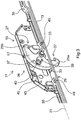
- fitting assembly 11 includes a faceplate 13 and attached to the faceplate 13 storage portion in the form of a closure box 15.
- the closure box 15 is designed specifically for insertion into a recess in a fold of a wing of a window, a door or the like.
- the front housing half 16 of the lock box 15 is omitted in order to illustrate the position of the components located in the lock box 15.
- a locking element 17 is housed in the closure box 15 and mounted by means of a pivot pin 19 about its longitudinal axis 20 pivotally mounted on the closure box 15.
- the longitudinal axis 20 of the pivot pin 19 in this case extends at right angles to the longitudinal axis 21 of the faceplate 13th
- the locking element 17 is executed in the illustrated embodiment of the invention as a plate-shaped component. As shown, it has two hook elements 25a, 25b, which are curved in opposite directions and arranged so that their free ends 27 face each other. In the in Fig. 4 shown pivot position of the locking element 17 are both hook elements 25a, 25b within the lock box 15, wherein no portion of the locking member 17 protrudes beyond the front side 29 of the faceplate 13. Therefore, the hook elements 25a, 25b are both in a release position here.
- each of the hook elements 25a, 25b are pivoted out through a corresponding opening 33 of the faceplate 13 from the closure box 15, as for the left hook member 25a in FIG Fig. 1-3 is shown.
- the hook element 25a an associated closing part (not shown) engage behind, which is arranged on another fitting part, a blend or sash profile or a threshold. That is, the hook element 25a pivoted out of the closure box 15 is in a locking position.
- the right in the image hook element 25b is pivotally in such a locking position and that due to the arrangement of the two hook elements 25a, 25b only one of them can be in the pivoted-out locking position.
- a transfer device 36 is provided with a slide control 37.
- a guide slot in the form of a slot 39 is formed, in which a sliding block 40 is added.
- the sliding block 40 is connected at one of the longitudinal axis 20 of the pivot pin 19 spaced location with a control slide 43 which is mounted along the longitudinal axis 21 of the faceplate 13 slidably in the closure box 15 and coupled to the drive rods 35.
- the spool 43 comprises two parallel control plates 45, between which the locking element 17 is arranged.
- the coupling of the control plates 45 with the drive rods 35 via formed on the end faces of the control plates 45 engagement lugs 47 which engage positively in matching recesses 49 of the drive rods 35.
- the fitting arrangement 11 described above can thus be carried out as a turn-tilt closure, wherein the in Fig. 1-3 shown pivot position of the locking element 17 a closed position of the turn-tilt closure, the in Fig. 4 shown pivot position of the locking element 17 an open position of the turn-tilt closure and that pivot position of the locking element 17, not shown, in which the right hook member 25b is pivoted out of the closure box 15, corresponds to a tilted position of the turn-tilt closure. Both in the closed position and in the tilted position of the corresponding window or door is reliably secured against digging.
Landscapes
- Engineering & Computer Science (AREA)
- Structural Engineering (AREA)
- Mechanical Engineering (AREA)
- Wing Frames And Configurations (AREA)
Description
Die vorliegende Erfindung betrifft eine Beschlaganordnung für ein Fenster, eine Tür oder dergleichen, mit einem Lagerungsabschnitt, der zur direkten oder indirekten Befestigung an einem Blend- oder Flügelrahmen des Fensters, der Tür oder dergleichen ausgebildet ist, und einem Riegelelement, das um eine Schwenkachse schwenkbar an dem Lagerungsabschnitt gelagert ist.The present invention relates to a fitting assembly for a window, a door or the like, comprising a support portion adapted for direct or indirect attachment to a window sash or sash, door or the like, and a latch member pivotable about a pivot axis is stored at the storage section.
Derartige Beschlaganordnungen werden im Allgemeinen als "Verschlüsse" bezeichnet und dazu verwendet, einen beweglichen Flügel eines Fensters, einer Tür oder dergleichen gegenüber einem weiteren beweglichen Flügel des Fensters, der Tür oder dergleichen oder gegenüber einem ortsfesten Element wie einem Blendrahmen oder einer Bodenschwelle wahlweise zu verriegeln oder freizugeben. Der Lagerungsabschnitt kann insbesondere an einer Stulpschiene angebracht oder direkt an dieser ausgebildet sein, welche ihrerseits zur Befestigung an einem entsprechenden Rahmenelement vorgesehen ist. Es ist also nicht zwingend notwendig, den Lagerungsabschnitt selbst am Blend- oder Flügelrahmen zu befestigen. Zum Verriegeln des Flügels wird das Riegelelement derart geschwenkt, dass es in Eingriff mit einem Schließteil gelangt, das an oder in einem anderen Beschlagteil, einem Rahmenelement, einer Bodenschwelle oder dergleichen angeordnet ist.Such hardware assemblies are commonly referred to as "closures" and are used to selectively lock a movable wing of a window, door or the like to another movable wing of the window, door or the like, or to a stationary member such as a frame or floor sill or release. The storage section can in particular be attached to a faceplate or be formed directly on this, which in turn is provided for attachment to a corresponding frame member. So it is not absolutely necessary to attach the storage section itself on the glare or sash. For locking the wing, the locking element is pivoted such that it comes into engagement with a closing part which is arranged on or in another fitting part, a frame element, a threshold or the like.
Schließteile, die von einer Beschlagteiloberfläche oder vom Boden abstehen, werden allgemein als störend empfunden. Dies gilt insbesondere bei solchen Verschlüssen, die für eine waagerechte Montage an der Flügelunterseite vorgesehen sind. Bei solchen Beschlaganordnungen stehen die vom Boden oder von der Bodenschwelle abstehenden Schließteile außerdem einer barrierefreien Konstruktion entgegen. Ein weiteres Problem besteht darin, dass gängige Beschläge mit schwenkbarem Riegelelement lediglich eine einzelne Verriegelungsstellung definieren und sich daher z. B. kaum für Dreh-Kipp-Verschlüsse eignen.Locking parts which protrude from a fitting part surface or from the floor are generally perceived as disturbing. This is especially true for such closures, which are intended for horizontal mounting on the wing underside. In such fitting arrangements, the locking members protruding from the floor or from the threshold are also barrier-free opposite. Another problem is that common fittings with pivoting locking element define only a single locking position and therefore z. B. hardly suitable for turn-tilt closures.
Die
Es ist eine Aufgabe der Erfindung, eine Beschlaganordnung der eingangs genannten Art anzugeben, welche flexibler einsetzbar ist und eine barrierefreie Konstruktion erlaubt.It is an object of the invention to provide a fitting arrangement of the type mentioned, which is more flexible and allows a barrier-free construction.
Die Lösung der Aufgabe erfolgt durch eine Beschlaganordnung mit den Merkmalen des Anspruchs 1.The object is achieved by a fitting arrangement with the features of claim 1.
Erfindungsgemäß ist vorgesehen, dass das Riegelelement ein erstes und ein zweites Hakenelement zum Hintergreifen eines Schließteils umfasst und dass das Riegelelement ein Doppelhaken mit zwei freien Hakenspitzen ist, wobei sich in einer ersten Schwenkstellung des Riegelelements das erste Hakenelement in einer ausgeschwenkten Verriegelungsstellung befindet, wobei sich in einer zweiten Schwenkstellung des Riegelelements das zweite Hakenelement in einer ausgeschwenkten Verriegelungsstellung befindet, und wobei sich in einer dritten Schwenkstellung des Riegelelements beide Hakenelemente in einer eingeschwenkten Freigabestellung befinden.According to the invention, it is provided that the locking element comprises a first and a second hook element for engaging behind a closing part and that the locking element is a double hook with two free hook tips, wherein in a first pivot position of the locking element, the first hook element is in a pivoted-out locking position, wherein in a second pivot position of the locking element, the second hook element is in a pivoted-out locking position, and wherein in a third pivot position of the locking element both hook elements are in a pivoted-release position.
Der Begriff "Ausschwenken" ist in dem Sinne zu verstehen, dass das betreffende Hakenelement in Richtung des zugehörigen Schließteils in den Außenraum der Beschlaganordnung bewegt wird. In analoger Weise ist der Begriff "Einschwenken" so zu verstehen, dass das betreffende Hakenelement von dem zugehörigen Schließteil weg in eine zurückgezogene Stellung bewegt wird. Aufgrund der beiden Hakenelemente gibt es bei einer erfindungsgemäßen Beschlaganordnung sowohl eine Freigabestellung als auch zwei voneinander unabhängige Verriegelungsstellungen. Somit kann z. B. ein Fixpunkt für eine Drehstellung des betreffenden Flügels und zusätzlich ein weiterer Fixpunkt für eine Kippstellung des Flügels realisiert werden. Grundsätzlich könnte das Riegelelement auch mehr als zwei Hakenelemente umfassen. Die Hakenelemente können in einfacher Weise in jeweilige Hakenaufnahmen hineingeschwenkt werden und dort geeignete Schließteile hintergreifen, so dass keine abstehenden Schließteile erforderlich sind. Durch den Hakeneingriff ist unter anderem eine besonders zuverlässige Aushebesicherung eines Fenster- oder Türflügels möglich.The term "swinging out" is to be understood in the sense that the relevant hook element is moved in the direction of the associated closing part in the outer space of the fitting assembly. Analogously, the term "pivoting" is to be understood that the relevant hook element of the associated Closing part is moved away in a retracted position. Due to the two hook elements, there is a release arrangement according to the invention both a release position and two mutually independent locking positions. Thus, z. B. a fixed point for a rotational position of the relevant wing and additionally a further fixed point for a tilted position of the wing can be realized. In principle, the locking element could also comprise more than two hook elements. The hook elements can be easily pivoted into respective hook receptacles and engage there behind suitable closing parts, so that no protruding closing parts are required. The hook intervention, inter alia, a particularly reliable lifting of a window or door leaf is possible.
Es ist bevorzugt, dass die erste Schwenkstellung und die zweite Schwenkstellung jeweilige Endlagen des Schwenkbereichs des Riegelelements definieren und sich die dritte Schwenkstellung zwischen der ersten Schwenkstellung und der zweiten Schwenkstellung befindet. Somit kann das Riegelelement in einem Zug von einer der Verriegelungsstellungen über die Freigabestellung bis in die andere Verriegelungsstellung geschwenkt werden. Bei einem derart gestalteten Verschluss ist insbesondere ein Umschalten von einer Schließstellung über eine Freigabestellung in eine Kippstellung möglich, wobei der betreffende Flügel aufgrund des Hakeneingriffs sowohl in der Schließstellung als auch in der Kippstellung gegen Ausheben gesichert ist.It is preferred that the first pivot position and the second pivot position define respective end positions of the pivotal range of the latch member and the third pivot position is between the first pivot position and the second pivot position. Thus, the locking element can be pivoted in one go from one of the locking positions on the release position to the other locking position. In a closure designed in this way, it is possible, in particular, to switch over from a closed position via a release position into a tilted position, the respective wing being secured against being lifted due to the hook engagement both in the closed position and in the tilted position.
Eine erfindungsgemäße Beschlaganordnung kann insbesondere als Dreh-Kipp-Verschluss ausgeführt sein, wobei die erste Schwenkstellung des Riegelelements einer Schließstellung des Dreh-Kipp-Verschlusses, die zweite Schwenkstellung des Riegelelements einer Kippstellung des Dreh-Kipp-Verschlusses und die dritte Schwenkstellung des Riegelelements einer Öffnungsstellung des Dreh-Kipp-Verschlusses entspricht. Ein solchermaßen gestalteter Verschluss kann in gewohnter Weise betätigt werden.A fitting arrangement according to the invention can be designed in particular as a turn-tilt closure, wherein the first pivot position of the locking element of a closed position of the turn-tilt closure, the second pivot position of the locking element of a tilted position of the tilt and turn closure and the third pivot position of the locking element of an open position corresponds to the turn-tilt closure. Such a shaped closure can be operated in the usual way.
Vorzugsweise sind die Hakenelemente gegensinnig gekrümmt, sodass eine symmetrische Ausgestaltung des Riegelelements möglich ist. Die freien Enden der Hakenelemente, also die Hakenspitzen, können voneinander weg weisen.Preferably, the hook elements are curved in opposite directions, so that a symmetrical configuration of the locking element is possible. The free ends of the hook elements, so the hook tips can point away from each other.
Bevorzugt ist jedoch vorgesehen, dass die freien Enden der Hakenelemente aufeinander zu weisen, sich also gewissermaßen gegenüberliegen. Dadurch kann nämlich der Schwenkweg des Riegelelements von der einen bis zur anderen Eingriffsstellung relativ kurz, beispielsweise bei weniger als 90°, gehalten werden.Preferably, however, it is provided that the free ends of the hook elements face each other, so in a sense opposite. As a result, namely, the pivoting of the locking element from one to the other engagement position can be kept relatively short, for example at less than 90 °.
Der Lagerungsabschnitt kann an einer Stulpschiene angeordnet sein, welche wenigstens eine Öffnung aufweist, durch welche die Hakenelemente ausschwenkbar sind. Je nach Anwendung kann eine gemeinsame Öffnung für beide Hakenelemente vorgesehen sein oder es können jeweilige Öffnungen für jedes der Hakenelemente vorgesehen sein. Bei der Öffnung kann es sich im einfachsten Fall um eine rechteckige Aussparung in der Stulpschiene handeln. Der Lagerungsabschnitt kann direkt oder indirekt an der Stulpschiene befestigt oder einstückig mit dieser ausgeführt sein.The storage section can be arranged on a face-plate rail which has at least one opening through which the hook elements can be swung out. Depending on the application, a common opening may be provided for both hook elements, or respective openings may be provided for each of the hook elements. In the simplest case, the opening can be a rectangular recess in the face-plate rail. The storage section can be attached directly or indirectly to the faceplate or be made in one piece with this.
Es ist bevorzugt, dass in der dritten Schwenkstellung des Riegelelements kein Abschnitt desselben durch die wenigstens eine Öffnung der Stulpschiene hindurchragt. Dies kann beispielsweise dadurch erreicht werden, dass bei einer Schwenkbewegung des Riegelelements von der ersten in die zweite Schwenkstellung das Hindurchtreten des zweiten Hakenelements durch die zugehörige Öffnung erst beginnt, nachdem das erste Hakenelement zumindest bis zur Vorderseite der Stulpschiene zurückbewegt ist, oder umgekehrt. Bei einer Montage des Verschlusses am unteren Rand des Flügels kann die Beschlagunterseite somit in unmittelbarer Bodennähe verlaufen, was in Verbindung mit einer bodenseitigen Hakenaufnahme eine barrierefreie Gestaltung ermöglicht.It is preferred that, in the third pivoting position of the locking element, no portion thereof projects through the at least one opening of the face-plate rail. This can be achieved, for example, by the fact that, upon a pivoting movement of the locking element from the first to the second pivot position, the passage of the second hook element through the associated opening only begins after the first hook element has been moved back at least to the front of the face plate, or vice versa. During assembly of the closure at the lower edge of the wing, the underside of the fitting can thus run in the immediate vicinity of the floor, which, in conjunction with a bottom hook receptacle, enables barrier-free design.
Es ist bevorzugt, dass die Schwenkachse rechtwinklig zu einer Längsachse der Stulpschiene verläuft. Das heißt es ist ein stulpseitiges Ein- und Ausschwenken des Riegelelements bevorzugt.It is preferred that the pivot axis extends at right angles to a longitudinal axis of the faceplate rail. That is, it is a stulpseitiges pivoting in and out of the locking element is preferred.
Eine erfindungsgemäße Beschlaganordnung kann einen an dem Lagerungsabschnitt linear verschiebbar gelagerten Steuerschieber und eine Umsetzeinrichtung aufweisen, wobei die Umsetzeinrichtung dazu ausgebildet ist, eine Verschiebebewegung des Steuerschiebers in eine Schwenkbewegung des Riegelelements umzusetzen. Eine solche Beschlaganordnung ist besonders gut in bestehende Treibstangensysteme integrierbar. Insbesondere kann der Steuerschieber mit einer Treibstange koppelbar sein, beispielsweise über geeignete Formschlusselemente. Weiterhin kann der Steuerschieber plattenförmig sein, um eine besonders einfache Fertigung zu ermöglichen.A fitting arrangement according to the invention can have a control slide mounted linearly displaceably on the mounting section and a conversion device, wherein the conversion device is designed to convert a displacement movement of the control slide into a pivoting movement of the locking element. Such a fitting arrangement is particularly well integrated into existing drive rod systems. In particular, the control slide can be coupled to a drive rod, for example via suitable positive locking elements. Furthermore, the spool may be plate-shaped to allow a particularly simple production.
Gemäß einer Ausgestaltung der Erfindung umfasst die Umsetzeinrichtung eine Kulissensteuerung mit einer Führungskulisse und einem in dieser aufgenommenen Kulissenstein, wobei die Führungskulisse an dem Riegelelement ausgebildet ist und der Kulissenstein an dem Steuerschieber angeordnet ist, oder umgekehrt. Dies ermöglicht eine besonders einfache und zuverlässige Konstruktion.According to one embodiment of the invention, the conversion device comprises a link control with a guide slot and a sliding block received in this, wherein the guide slot is formed on the locking element and the sliding block is arranged on the spool, or vice versa. This allows a particularly simple and reliable construction.
Vorzugsweise ist der Kulissenstein von der Schwenkachse beabstandet. Eine Bewegung des Steuerschiebers wird somit stets in ein auf das Riegelelement einwirkendes Drehmoment umgesetzt.Preferably, the sliding block is spaced from the pivot axis. A movement of the spool is thus always converted into an acting on the locking element torque.
Das Riegelelement kann als einstückiges, vorzugsweise plattenförmiges, Bauteil ausgeführt sein, um die Herstellungskosten gering zu halten.The locking element can be designed as a one-piece, preferably plate-shaped, component in order to keep the manufacturing costs low.
Gemäß einer speziellen Ausgestaltung der Erfindung ist der Lagerungsabschnitt zum Einsetzen in eine Beschlagnut des Fensters, der Tür oder dergleichen ausgebildet.According to a particular embodiment of the invention, the storage portion is designed for insertion into a fitting groove of the window, the door or the like.
Es kann vorgesehen sein, dass der Lagerungsabschnitt gehäuseartig ausgebildet ist und das Riegelelement in dem gehäuseartigen Lagerungsabschnitt untergebracht ist. Eine gehäuseartige Ausführung des Lagerungsabschnitts erleichtert dessen Einsetzen in eine Beschlagnut und schützt außerdem die beweglichen Komponenten.It can be provided that the storage section is formed like a housing and the locking element is housed in the housing-like storage section. A box-like design of the storage section facilitates its insertion into a fitting groove and also protects the movable components.
Weiterbildungen der Erfindung sind auch in den abhängigen Ansprüchen, der Beschreibung sowie den beigefügten Zeichnungen angegeben.Further developments of the invention are set forth in the dependent claims, the description and the accompanying drawings.
Die Erfindung wird nachfolgend beispielhaft unter Bezugnahme auf die Zeichnung beschrieben.
- Fig. 1
- ist eine Teildarstellung einer erfindungsgemäßen Beschlaganordnung für Fenster, Türen oder dergleichen, wobei sich ein Riegelelement der Beschlaganordnung in einer Verriegelungsstellung befindet.
- Fig. 2
- zeigt die Beschlaganordnung gemäß
Fig. 1 mit geöffnetem Verschlusskasten. - Fig. 3
- zeigt die Beschlaganordnung gemäß
Fig. 2 mit einer entfernten Steuerplatte. - Fig. 4
- zeigt die Beschlaganordnung gemäß
Fig. 3 , wobei sich das Riegelelement in einer Freigabestellung befindet.
- Fig. 1
- is a partial view of a fitting arrangement according to the invention for windows, doors or the like, wherein a locking element of the fitting arrangement is in a locking position.
- Fig. 2
- shows the fitting arrangement according to
Fig. 1 with open lock box. - Fig. 3
- shows the fitting arrangement according to
Fig. 2 with a remote control panel. - Fig. 4
- shows the fitting arrangement according to
Fig. 3 , wherein the locking element is in a release position.
Die in
Wie insbesondere aus
Das Riegelelement 17 ist bei der gezeigten Ausführungsform der Erfindung als plattenförmiges Bauteil ausgeführt. Wie dargestellt weist es zwei Hakenelemente 25a, 25b auf, die gegensinnig gekrümmt und derart angeordnet sind, dass ihre freien Enden 27 aufeinander zu weisen. In der in
Durch Schwenken des Riegelelements 17 ausgehend von der in
Das Umschalten des Riegelelements 17 zwischen den drei verschiedenen Funktionsstellungen erfolgt mittels einer Anordnung aus Treibstangen 35, die in grundsätzlich bekannter Weise an der Stulpschiene 13 verschiebbar geführt und mit einem betätigbaren Beschlaggetriebe (nicht dargestellt) gekoppelt sind. Zum Umsetzen der linearen Verschiebebewegung der Treibstangen 35 in eine Schwenkbewegung des Riegelelements 17 ist eine Umsetzeinrichtung 36 mit einer Kulissensteuerung 37 vorgesehen. Wie insbesondere aus
Wenn das Riegelelement 17 über die Kulissensteuerung 37 ausgehend von der in
Die vorstehend beschriebene Beschlaganordnung 11 kann somit als Dreh-Kipp-Verschluss ausgeführt werden, wobei die in
Es versteht sich, dass anstelle des gehäuseartigen Verschlusskastens 15 ein beliebig geformter Lagerungsabschnitt, beispielsweise in Form einer einfachen Platte, vorgesehen sein kann. Anstelle eines "Herausschwenkens" des Riegelelements 17 aus dem Verschlusskasten 15 bzw. eines "Hineinschwenkens" des Riegelelements 17 in den Verschlusskasten 15 würde in diesem Fall ein "Ausschwenken" des Riegelelements 17 aus dem bezüglich der Stulpschiene 13 rückwärtigen Raum bzw. ein "Einschwenken" des Riegelelements 17 in diesen rückwärtigen Raum erfolgen.It is understood that instead of the box-
Dadurch dass der Riegeleingriff des Dreh-Kipp-Verschlusses über schwenkbare Hakenelemente 25a, 25b erfolgt, die einerseits in versenkte Riegelaufnahmen eingreifen können und andererseits in der Öffnungsstellung des Dreh-Kipp-Verschlusses nicht über die Vorderseite 29 der Stulpschiene 13 hinausragen, kann bei einer Montage des Dreh-Kipp-Verschlusses an der Flügelunterseite die Stulpschiene 13 besonders nah über dem Boden geführt werden, um so zum Beispiel die Vorgaben eines "barrierefreien Bauens" zu erfüllen.The fact that the locking engagement of the tilt and turn closure via
- 1111
- Beschlaganordnungfitting assembly
- 1313
- Stulpschienefaceplate
- 1515
- Verschlusskastenlock box
- 1616
- vordere Gehäusehälftefront housing half
- 1717
- Riegelelementlocking element
- 1919
- Schwenkzapfenpivot pin
- 2020
- Längsachse des SchwenkzapfensLongitudinal axis of the pivot pin
- 2121
- Längsachse der StulpschieneLongitudinal axis of the faceplate
- 25a, 25b25a, 25b
- Hakenelementhook element
- 2727
- freies Endefree end
- 2929
- Vorderseite der StulpschieneFront of the faceplate
- 3333
- Öffnungopening
- 3535
- Treibstangedriving rod
- 3636
- UmsetzeinrichtungTranscriber
- 3737
- Kulissensteuerunglink motion
- 3939
- LanglochLong hole
- 4040
- Kulissensteinsliding block
- 4343
- Steuerschieberspool
- 4545
- Steuerplattecontrol plate
- 4747
- Eingriffsnaseengaging nose
- 4949
- Ausnehmungrecess
Claims (14)
- A fitting arrangement (11) for a window, for a door or the like, having a support section (15) which is configured for a direct or indirect fastening to a frame or leaf frame of the window, of the door or the like;
and having a latch element (17) which is pivotably supported about a pivot axis (20) at the support section (15),
wherein the latch element (17) comprises first and second hook elements (25a, 25b) for engaging behind a closure part, and wherein the latch element (17) is a double hook having two free hook tips (27);wherein the first hook element (25a) is located in an outwardly pivoted latched position in a first pivot position of the latch element (17);wherein the second hook element (25b) is located in an outwardly pivoted latched position in a second pivot position of the latch element (17);and wherein both hook elements (25a, 25b) are located in an inwardly pivoted release position in a third pivot position of the latch element (17). - A fitting arrangement in accordance with claim 1,
characterized in that
the first pivot position and the second pivot position define respective end positions of the pivot range of the latch element (17) and the third pivot position is located between the first pivot position and the second pivot position. - A fitting arrangement in accordance with claim 1 or claim 2,
characterized in that
the fitting arrangement (11) is configured as a turn and tilt closure, with the first pivot position of the latch element (17) corresponding to a closed position of the turn and tilt closure, the second pivot position of the latch element (17) corresponding to a tilt position of the turn and tilt closure and the third pivot position of the latch element (17) corresponding to an open position of the turn and tilt closure. - A fitting arrangement in accordance with any one of the preceding claims,
characterized in that
the hook elements (25a, 25b) are curved in opposite senses. - A fitting arrangement in accordance with any one of the preceding claims,
characterized in that
the free ends (27) of the hook elements (25a, 25b) face toward one another. - A fitting arrangement in accordance with any one of the preceding claims,
characterized in that
the support section (15) is arranged at a cover rail (13) which has at least one opening (33) through which the hook elements (25a, 25b) can be outwardly pivoted. - A fitting arrangement in accordance with claim 6,
characterized in that
no section of the latch element (17) projects through the at least one opening (33) of the cover rail (13) in the third pivot position of said latch element (17). - A fitting arrangement in accordance with claim 6 or claim 7,
characterized in that
the pivot axis (20) extends at a right angle to a longitudinal axis (21) of the cover rail (13). - A fitting arrangement in accordance with any one of the preceding claims,
characterized by
a control slide (43) linearly displaceably supported at the support section (15); and by a conversion device (36) which is configured to convert a displacement movement of the control slide (43) into a pivot movement of the latch element (17). - A fitting arrangement in accordance with claim 9,
characterized in that
the conversion device (36) comprises a slot control (37) having a guide slot (39) and having a sliding block (40) received therein, with the guide slot (39) being formed at the latch element (17) and the sliding block (40) being arranged at the control slide (43), or vice versa. - A fitting arrangement in accordance with claim 10,
characterized in that
the sliding block (40) is spaced apart from the pivot axis (20). - A fitting arrangement in accordance with any one of the preceding claims,
characterized in that
the latch element (17) is designed as a single-piece component which is preferably plate-shaped. - A fitting arrangement in accordance with any one of the preceding claims,
characterized in that
the support section (15) is configured for insertion into a fitting groove of the window, of the door or the like. - A fitting arrangement in accordance with any one of the preceding claims,
characterized in that
the support section (15) is formed in the manner of a housing and the latch element (17) is accommodated in the housing-like support section.
Applications Claiming Priority (2)
| Application Number | Priority Date | Filing Date | Title |
|---|---|---|---|
| DE102015120954.3A DE102015120954A1 (en) | 2015-12-02 | 2015-12-02 | fitting assembly |
| PCT/EP2016/079162 WO2017093268A1 (en) | 2015-12-02 | 2016-11-29 | Fitting assembly |
Publications (2)
| Publication Number | Publication Date |
|---|---|
| EP3371397A1 EP3371397A1 (en) | 2018-09-12 |
| EP3371397B1 true EP3371397B1 (en) | 2019-11-27 |
Family
ID=57471848
Family Applications (1)
| Application Number | Title | Priority Date | Filing Date |
|---|---|---|---|
| EP16805370.0A Active EP3371397B1 (en) | 2015-12-02 | 2016-11-29 | Fitting assembly |
Country Status (3)
| Country | Link |
|---|---|
| EP (1) | EP3371397B1 (en) |
| DE (1) | DE102015120954A1 (en) |
| WO (1) | WO2017093268A1 (en) |
Families Citing this family (2)
| Publication number | Priority date | Publication date | Assignee | Title |
|---|---|---|---|---|
| DE102017218071A1 (en) | 2017-10-11 | 2019-04-11 | Aug. Winkhaus Gmbh & Co. Kg | Closure for a drive rod fitting |
| CN109025576A (en) * | 2018-06-20 | 2018-12-18 | 亚萨合莱国强(山东)五金科技有限公司 | A kind of door and window hook-type lock point driver |
Family Cites Families (5)
| Publication number | Priority date | Publication date | Assignee | Title |
|---|---|---|---|---|
| DE3822343C2 (en) * | 1988-07-01 | 1995-03-16 | Boris Fipke | Additional safety device for windows |
| DE10134249A1 (en) * | 2001-07-18 | 2003-01-30 | Roto Frank Ag | Locking fitment for window casement or door leaf to fixed frame has bolt element and thrust piece, pivot axle with drive adjustment |
| DE202008009023U1 (en) * | 2008-07-07 | 2009-11-12 | Kfv Karl Fliether Gmbh & Co. Kg | Closure for windows or doors |
| DE102009000746A1 (en) * | 2009-02-10 | 2010-08-12 | Aug. Winkhaus Gmbh & Co. Kg | Closure for a drive rod fitting |
| DE202011102905U1 (en) * | 2011-07-06 | 2012-10-11 | Maco Technologie Gmbh | lock |
-
2015
- 2015-12-02 DE DE102015120954.3A patent/DE102015120954A1/en not_active Withdrawn
-
2016
- 2016-11-29 WO PCT/EP2016/079162 patent/WO2017093268A1/en active Application Filing
- 2016-11-29 EP EP16805370.0A patent/EP3371397B1/en active Active
Non-Patent Citations (1)
| Title |
|---|
| None * |
Also Published As
| Publication number | Publication date |
|---|---|
| DE102015120954A1 (en) | 2017-06-08 |
| EP3371397A1 (en) | 2018-09-12 |
| WO2017093268A1 (en) | 2017-06-08 |
Similar Documents
| Publication | Publication Date | Title |
|---|---|---|
| DE102017129427B3 (en) | hinge closure | |
| EP0119433B2 (en) | Fitting for a wing of a window, door or the like, which is at least tiltable and movable from one plane to a second parallel plane | |
| EP3371397B1 (en) | Fitting assembly | |
| DE102008062950A1 (en) | Fitting with retractable locking element | |
| DE3334298C3 (en) | Lock for windows, doors or the like | |
| DE8711496U1 (en) | Lock for double-leaf windows, doors, etc. | |
| EP4105416A1 (en) | Fixing device for door mounted on both sides | |
| DE102013203488A1 (en) | opening limiter | |
| EP3235988A1 (en) | Window system and/or door system | |
| DE102014226794A1 (en) | Fitting for installation between a wing and a fixed frame of a window, a door or the like and window, door or the like with such a fitting | |
| EP1790805B1 (en) | Drive with a lever gear for an espagnolette | |
| EP1590548B1 (en) | Pivoting tilting mounting | |
| DE102004060717B4 (en) | Lock for locking a wing in a frame of a window | |
| DE102014117419A1 (en) | Hardware for windows, doors and the like and gear unit for such a fitting | |
| EP3215696B1 (en) | Lock | |
| DE102014111131A1 (en) | Device for locking and unlocking a window sash, a ventilation flap or the like on a window frame | |
| EP2320013B1 (en) | Fitting with a reversing gear | |
| EP2754795B1 (en) | Strike box or mortise lock | |
| EP2182149B1 (en) | Pulling device for an espagnolette fitting | |
| DE2457169A1 (en) | Door or window edge lock - has path of motion of connecting rod or locking pin bounded by half path motion directions | |
| EP3647529B1 (en) | Actuator for a door seal with a liftable and retractable seal strip | |
| DE102004054979B4 (en) | Window, door or the like with a planar locking device | |
| DE2020240B2 (en) | LOCK FOR A TILTING-TILT SASH OF A WINDOW, A DOOR OR DGL. | |
| EP4174266A1 (en) | Wing assembly | |
| EP3194697B1 (en) | Fitting arrangement |
Legal Events
| Date | Code | Title | Description |
|---|---|---|---|
| STAA | Information on the status of an ep patent application or granted ep patent |
Free format text: STATUS: UNKNOWN |
|
| STAA | Information on the status of an ep patent application or granted ep patent |
Free format text: STATUS: THE INTERNATIONAL PUBLICATION HAS BEEN MADE |
|
| PUAI | Public reference made under article 153(3) epc to a published international application that has entered the european phase |
Free format text: ORIGINAL CODE: 0009012 |
|
| STAA | Information on the status of an ep patent application or granted ep patent |
Free format text: STATUS: REQUEST FOR EXAMINATION WAS MADE |
|
| 17P | Request for examination filed |
Effective date: 20180608 |
|
| AK | Designated contracting states |
Kind code of ref document: A1 Designated state(s): AL AT BE BG CH CY CZ DE DK EE ES FI FR GB GR HR HU IE IS IT LI LT LU LV MC MK MT NL NO PL PT RO RS SE SI SK SM TR |
|
| AX | Request for extension of the european patent |
Extension state: BA ME |
|
| DAV | Request for validation of the european patent (deleted) | ||
| DAX | Request for extension of the european patent (deleted) | ||
| GRAP | Despatch of communication of intention to grant a patent |
Free format text: ORIGINAL CODE: EPIDOSNIGR1 |
|
| STAA | Information on the status of an ep patent application or granted ep patent |
Free format text: STATUS: GRANT OF PATENT IS INTENDED |
|
| GRAJ | Information related to disapproval of communication of intention to grant by the applicant or resumption of examination proceedings by the epo deleted |
Free format text: ORIGINAL CODE: EPIDOSDIGR1 |
|
| STAA | Information on the status of an ep patent application or granted ep patent |
Free format text: STATUS: REQUEST FOR EXAMINATION WAS MADE |
|
| INTG | Intention to grant announced |
Effective date: 20190507 |
|
| GRAP | Despatch of communication of intention to grant a patent |
Free format text: ORIGINAL CODE: EPIDOSNIGR1 |
|
| STAA | Information on the status of an ep patent application or granted ep patent |
Free format text: STATUS: GRANT OF PATENT IS INTENDED |
|
| INTG | Intention to grant announced |
Effective date: 20190613 |
|
| GRAS | Grant fee paid |
Free format text: ORIGINAL CODE: EPIDOSNIGR3 |
|
| GRAA | (expected) grant |
Free format text: ORIGINAL CODE: 0009210 |
|
| STAA | Information on the status of an ep patent application or granted ep patent |
Free format text: STATUS: THE PATENT HAS BEEN GRANTED |
|
| AK | Designated contracting states |
Kind code of ref document: B1 Designated state(s): AL AT BE BG CH CY CZ DE DK EE ES FI FR GB GR HR HU IE IS IT LI LT LU LV MC MK MT NL NO PL PT RO RS SE SI SK SM TR |
|
| REG | Reference to a national code |
Ref country code: GB Ref legal event code: FG4D Free format text: NOT ENGLISH |
|
| REG | Reference to a national code |
Ref country code: CH Ref legal event code: EP |
|
| REG | Reference to a national code |
Ref country code: AT Ref legal event code: REF Ref document number: 1206827 Country of ref document: AT Kind code of ref document: T Effective date: 20191215 |
|
| REG | Reference to a national code |
Ref country code: DE Ref legal event code: R096 Ref document number: 502016007802 Country of ref document: DE |
|
| REG | Reference to a national code |
Ref country code: IE Ref legal event code: FG4D Free format text: LANGUAGE OF EP DOCUMENT: GERMAN |
|
| REG | Reference to a national code |
Ref country code: NL Ref legal event code: MP Effective date: 20191127 |
|
| REG | Reference to a national code |
Ref country code: LT Ref legal event code: MG4D |
|
| PG25 | Lapsed in a contracting state [announced via postgrant information from national office to epo] |
Ref country code: FI Free format text: LAPSE BECAUSE OF FAILURE TO SUBMIT A TRANSLATION OF THE DESCRIPTION OR TO PAY THE FEE WITHIN THE PRESCRIBED TIME-LIMIT Effective date: 20191127 Ref country code: BG Free format text: LAPSE BECAUSE OF FAILURE TO SUBMIT A TRANSLATION OF THE DESCRIPTION OR TO PAY THE FEE WITHIN THE PRESCRIBED TIME-LIMIT Effective date: 20200227 Ref country code: NO Free format text: LAPSE BECAUSE OF FAILURE TO SUBMIT A TRANSLATION OF THE DESCRIPTION OR TO PAY THE FEE WITHIN THE PRESCRIBED TIME-LIMIT Effective date: 20200227 Ref country code: GR Free format text: LAPSE BECAUSE OF FAILURE TO SUBMIT A TRANSLATION OF THE DESCRIPTION OR TO PAY THE FEE WITHIN THE PRESCRIBED TIME-LIMIT Effective date: 20200228 Ref country code: LV Free format text: LAPSE BECAUSE OF FAILURE TO SUBMIT A TRANSLATION OF THE DESCRIPTION OR TO PAY THE FEE WITHIN THE PRESCRIBED TIME-LIMIT Effective date: 20191127 Ref country code: NL Free format text: LAPSE BECAUSE OF FAILURE TO SUBMIT A TRANSLATION OF THE DESCRIPTION OR TO PAY THE FEE WITHIN THE PRESCRIBED TIME-LIMIT Effective date: 20191127 Ref country code: SE Free format text: LAPSE BECAUSE OF FAILURE TO SUBMIT A TRANSLATION OF THE DESCRIPTION OR TO PAY THE FEE WITHIN THE PRESCRIBED TIME-LIMIT Effective date: 20191127 Ref country code: LT Free format text: LAPSE BECAUSE OF FAILURE TO SUBMIT A TRANSLATION OF THE DESCRIPTION OR TO PAY THE FEE WITHIN THE PRESCRIBED TIME-LIMIT Effective date: 20191127 |
|
| PG25 | Lapsed in a contracting state [announced via postgrant information from national office to epo] |
Ref country code: HR Free format text: LAPSE BECAUSE OF FAILURE TO SUBMIT A TRANSLATION OF THE DESCRIPTION OR TO PAY THE FEE WITHIN THE PRESCRIBED TIME-LIMIT Effective date: 20191127 Ref country code: RS Free format text: LAPSE BECAUSE OF FAILURE TO SUBMIT A TRANSLATION OF THE DESCRIPTION OR TO PAY THE FEE WITHIN THE PRESCRIBED TIME-LIMIT Effective date: 20191127 Ref country code: IS Free format text: LAPSE BECAUSE OF FAILURE TO SUBMIT A TRANSLATION OF THE DESCRIPTION OR TO PAY THE FEE WITHIN THE PRESCRIBED TIME-LIMIT Effective date: 20200327 |
|
| PG25 | Lapsed in a contracting state [announced via postgrant information from national office to epo] |
Ref country code: AL Free format text: LAPSE BECAUSE OF FAILURE TO SUBMIT A TRANSLATION OF THE DESCRIPTION OR TO PAY THE FEE WITHIN THE PRESCRIBED TIME-LIMIT Effective date: 20191127 |
|
| REG | Reference to a national code |
Ref country code: CH Ref legal event code: PL |
|
| PG25 | Lapsed in a contracting state [announced via postgrant information from national office to epo] |
Ref country code: DK Free format text: LAPSE BECAUSE OF FAILURE TO SUBMIT A TRANSLATION OF THE DESCRIPTION OR TO PAY THE FEE WITHIN THE PRESCRIBED TIME-LIMIT Effective date: 20191127 Ref country code: CH Free format text: LAPSE BECAUSE OF NON-PAYMENT OF DUE FEES Effective date: 20191130 Ref country code: LI Free format text: LAPSE BECAUSE OF NON-PAYMENT OF DUE FEES Effective date: 20191130 Ref country code: EE Free format text: LAPSE BECAUSE OF FAILURE TO SUBMIT A TRANSLATION OF THE DESCRIPTION OR TO PAY THE FEE WITHIN THE PRESCRIBED TIME-LIMIT Effective date: 20191127 Ref country code: PT Free format text: LAPSE BECAUSE OF FAILURE TO SUBMIT A TRANSLATION OF THE DESCRIPTION OR TO PAY THE FEE WITHIN THE PRESCRIBED TIME-LIMIT Effective date: 20200419 Ref country code: CZ Free format text: LAPSE BECAUSE OF FAILURE TO SUBMIT A TRANSLATION OF THE DESCRIPTION OR TO PAY THE FEE WITHIN THE PRESCRIBED TIME-LIMIT Effective date: 20191127 Ref country code: LU Free format text: LAPSE BECAUSE OF NON-PAYMENT OF DUE FEES Effective date: 20191129 Ref country code: RO Free format text: LAPSE BECAUSE OF FAILURE TO SUBMIT A TRANSLATION OF THE DESCRIPTION OR TO PAY THE FEE WITHIN THE PRESCRIBED TIME-LIMIT Effective date: 20191127 Ref country code: ES Free format text: LAPSE BECAUSE OF FAILURE TO SUBMIT A TRANSLATION OF THE DESCRIPTION OR TO PAY THE FEE WITHIN THE PRESCRIBED TIME-LIMIT Effective date: 20191127 |
|
| REG | Reference to a national code |
Ref country code: BE Ref legal event code: MM Effective date: 20191130 |
|
| REG | Reference to a national code |
Ref country code: DE Ref legal event code: R097 Ref document number: 502016007802 Country of ref document: DE |
|
| PG25 | Lapsed in a contracting state [announced via postgrant information from national office to epo] |
Ref country code: MC Free format text: LAPSE BECAUSE OF FAILURE TO SUBMIT A TRANSLATION OF THE DESCRIPTION OR TO PAY THE FEE WITHIN THE PRESCRIBED TIME-LIMIT Effective date: 20191127 Ref country code: SM Free format text: LAPSE BECAUSE OF FAILURE TO SUBMIT A TRANSLATION OF THE DESCRIPTION OR TO PAY THE FEE WITHIN THE PRESCRIBED TIME-LIMIT Effective date: 20191127 Ref country code: SK Free format text: LAPSE BECAUSE OF FAILURE TO SUBMIT A TRANSLATION OF THE DESCRIPTION OR TO PAY THE FEE WITHIN THE PRESCRIBED TIME-LIMIT Effective date: 20191127 |
|
| PLBE | No opposition filed within time limit |
Free format text: ORIGINAL CODE: 0009261 |
|
| STAA | Information on the status of an ep patent application or granted ep patent |
Free format text: STATUS: NO OPPOSITION FILED WITHIN TIME LIMIT |
|
| PG25 | Lapsed in a contracting state [announced via postgrant information from national office to epo] |
Ref country code: IE Free format text: LAPSE BECAUSE OF NON-PAYMENT OF DUE FEES Effective date: 20191129 |
|
| 26N | No opposition filed |
Effective date: 20200828 |
|
| PG25 | Lapsed in a contracting state [announced via postgrant information from national office to epo] |
Ref country code: PL Free format text: LAPSE BECAUSE OF FAILURE TO SUBMIT A TRANSLATION OF THE DESCRIPTION OR TO PAY THE FEE WITHIN THE PRESCRIBED TIME-LIMIT Effective date: 20191127 Ref country code: BE Free format text: LAPSE BECAUSE OF NON-PAYMENT OF DUE FEES Effective date: 20191130 Ref country code: SI Free format text: LAPSE BECAUSE OF FAILURE TO SUBMIT A TRANSLATION OF THE DESCRIPTION OR TO PAY THE FEE WITHIN THE PRESCRIBED TIME-LIMIT Effective date: 20191127 |
|
| PG25 | Lapsed in a contracting state [announced via postgrant information from national office to epo] |
Ref country code: CY Free format text: LAPSE BECAUSE OF FAILURE TO SUBMIT A TRANSLATION OF THE DESCRIPTION OR TO PAY THE FEE WITHIN THE PRESCRIBED TIME-LIMIT Effective date: 20191127 |
|
| GBPC | Gb: european patent ceased through non-payment of renewal fee |
Effective date: 20201129 |
|
| PG25 | Lapsed in a contracting state [announced via postgrant information from national office to epo] |
Ref country code: HU Free format text: LAPSE BECAUSE OF FAILURE TO SUBMIT A TRANSLATION OF THE DESCRIPTION OR TO PAY THE FEE WITHIN THE PRESCRIBED TIME-LIMIT; INVALID AB INITIO Effective date: 20161129 Ref country code: MT Free format text: LAPSE BECAUSE OF FAILURE TO SUBMIT A TRANSLATION OF THE DESCRIPTION OR TO PAY THE FEE WITHIN THE PRESCRIBED TIME-LIMIT Effective date: 20191127 |
|
| PG25 | Lapsed in a contracting state [announced via postgrant information from national office to epo] |
Ref country code: GB Free format text: LAPSE BECAUSE OF NON-PAYMENT OF DUE FEES Effective date: 20201129 |
|
| PG25 | Lapsed in a contracting state [announced via postgrant information from national office to epo] |
Ref country code: TR Free format text: LAPSE BECAUSE OF FAILURE TO SUBMIT A TRANSLATION OF THE DESCRIPTION OR TO PAY THE FEE WITHIN THE PRESCRIBED TIME-LIMIT Effective date: 20191127 |
|
| PG25 | Lapsed in a contracting state [announced via postgrant information from national office to epo] |
Ref country code: MK Free format text: LAPSE BECAUSE OF FAILURE TO SUBMIT A TRANSLATION OF THE DESCRIPTION OR TO PAY THE FEE WITHIN THE PRESCRIBED TIME-LIMIT Effective date: 20191127 |
|
| PGFP | Annual fee paid to national office [announced via postgrant information from national office to epo] |
Ref country code: IT Payment date: 20231124 Year of fee payment: 8 Ref country code: FR Payment date: 20231120 Year of fee payment: 8 Ref country code: DE Payment date: 20231121 Year of fee payment: 8 Ref country code: AT Payment date: 20231121 Year of fee payment: 8 |