EP3194697B1 - Fitting arrangement - Google Patents
Fitting arrangement Download PDFInfo
- Publication number
- EP3194697B1 EP3194697B1 EP15781076.3A EP15781076A EP3194697B1 EP 3194697 B1 EP3194697 B1 EP 3194697B1 EP 15781076 A EP15781076 A EP 15781076A EP 3194697 B1 EP3194697 B1 EP 3194697B1
- Authority
- EP
- European Patent Office
- Prior art keywords
- rail
- fitting
- fitting groove
- closure element
- frame
- Prior art date
- Legal status (The legal status is an assumption and is not a legal conclusion. Google has not performed a legal analysis and makes no representation as to the accuracy of the status listed.)
- Active
Links
- 238000006073 displacement reaction Methods 0.000 claims description 18
- 235000001674 Agaricus brunnescens Nutrition 0.000 claims description 10
- 238000003780 insertion Methods 0.000 description 10
- 230000037431 insertion Effects 0.000 description 10
- 230000004313 glare Effects 0.000 description 6
- 238000004519 manufacturing process Methods 0.000 description 6
- 230000005540 biological transmission Effects 0.000 description 5
- 206010053648 Vascular occlusion Diseases 0.000 description 3
- 238000010276 construction Methods 0.000 description 2
- 230000003670 easy-to-clean Effects 0.000 description 2
- 239000000203 mixture Substances 0.000 description 2
- 235000003332 Ilex aquifolium Nutrition 0.000 description 1
- 241000209027 Ilex aquifolium Species 0.000 description 1
- 238000004140 cleaning Methods 0.000 description 1
- 230000001419 dependent effect Effects 0.000 description 1
- 238000011161 development Methods 0.000 description 1
- 230000018109 developmental process Effects 0.000 description 1
- 230000009977 dual effect Effects 0.000 description 1
- 230000007717 exclusion Effects 0.000 description 1
- 230000002349 favourable effect Effects 0.000 description 1
- 238000012423 maintenance Methods 0.000 description 1
- 238000004826 seaming Methods 0.000 description 1
Images


Classifications
-
- E—FIXED CONSTRUCTIONS
- E05—LOCKS; KEYS; WINDOW OR DOOR FITTINGS; SAFES
- E05C—BOLTS OR FASTENING DEVICES FOR WINGS, SPECIALLY FOR DOORS OR WINDOWS
- E05C9/00—Arrangements of simultaneously actuated bolts or other securing devices at well-separated positions on the same wing
- E05C9/18—Details of fastening means or of fixed retaining means for the ends of bars
- E05C9/1825—Fastening means
- E05C9/1833—Fastening means performing sliding movements
- E05C9/1841—Fastening means performing sliding movements perpendicular to actuating bar
-
- E—FIXED CONSTRUCTIONS
- E05—LOCKS; KEYS; WINDOW OR DOOR FITTINGS; SAFES
- E05B—LOCKS; ACCESSORIES THEREFOR; HANDCUFFS
- E05B15/00—Other details of locks; Parts for engagement by bolts of fastening devices
- E05B15/02—Striking-plates; Keepers; Bolt staples; Escutcheons
- E05B15/0205—Striking-plates, keepers, staples
- E05B15/029—Closures, e.g. preventing dirt or paint from entering into the striker
-
- E—FIXED CONSTRUCTIONS
- E05—LOCKS; KEYS; WINDOW OR DOOR FITTINGS; SAFES
- E05C—BOLTS OR FASTENING DEVICES FOR WINGS, SPECIALLY FOR DOORS OR WINDOWS
- E05C9/00—Arrangements of simultaneously actuated bolts or other securing devices at well-separated positions on the same wing
- E05C9/18—Details of fastening means or of fixed retaining means for the ends of bars
- E05C9/1808—Keepers
-
- E—FIXED CONSTRUCTIONS
- E05—LOCKS; KEYS; WINDOW OR DOOR FITTINGS; SAFES
- E05C—BOLTS OR FASTENING DEVICES FOR WINGS, SPECIALLY FOR DOORS OR WINDOWS
- E05C9/00—Arrangements of simultaneously actuated bolts or other securing devices at well-separated positions on the same wing
- E05C9/18—Details of fastening means or of fixed retaining means for the ends of bars
- E05C9/1825—Fastening means
- E05C9/1833—Fastening means performing sliding movements
- E05C9/185—Fastening means performing sliding movements parallel with actuating bar
-
- E—FIXED CONSTRUCTIONS
- E05—LOCKS; KEYS; WINDOW OR DOOR FITTINGS; SAFES
- E05C—BOLTS OR FASTENING DEVICES FOR WINGS, SPECIALLY FOR DOORS OR WINDOWS
- E05C5/00—Fastening devices with bolts moving otherwise than only rectilinearly and only pivotally or rotatively
Definitions
- the present invention relates to a fitting arrangement for windows, doors or the like, in particular for plastic windows or plastic doors, with at least one face plate for at least partially covering a fitting groove, which is formed in a glare or sash of the window, the door or the like, at least one closure Element which is movable along a longitudinal extent of the fitting groove between a release position and a locking position, and a transmission which is operable to move the closure element.
- edge closures are also referred to as edge closures and are used for setting the closed casement on demand associated with the frame.
- edge seals are based on the fact that by means of the transmission, the z. B. operable by a handle or lever, a plurality of the sash frame movably mounted closure elements are brought into engagement with associated, attached to the frame closing parts, or conversely on the frame movably mounted closure elements into engagement with associated, attached to the sash closing parts to be brought.
- the faceplate here serves in general as the outer end of the fitting groove.
- the closure elements may for example be attached to a coupled to the transmission drive or locking bar and be displaceable together with this.
- the faceplate must in this case a suitable recess such. B. have a slot through which the closure element protrude and within which it can be moved.
- the forend of the associated glare or sash frame is difficult to clean.
- the protruding closure element may encounter when closing the wing against another fitting component, if the seaming air is too low due to manufacturing tolerances.
- the EP 2 206 860 A2 discloses a fitting with an extendable locking element which is to be moved together with a drive rod.
- the drive rod is covered by a fixed faceplate.
- the faceplate for a displaceable along the longitudinal extension bearing in the fitting groove is formed and the at least one closure element is displaceably mounted in and against an extending transversely to the longitudinal direction of extension on the face-plate.
- a control mechanism of the fitting arrangement in its assembled state ensures that the closure element firstly actuates the drive section in the extension direction from a position retracted into the face-plate into a position extended from the face-plate and subsequently in the extended state is moved together with the faceplate along the longitudinal extent of the fitting groove to move from the release position to the locking position.
- the faceplate is therefore not fixed as usual in the fitting groove, but slidably mounted on this.
- the shutter element so z.
- This construction is advantageous in that no screwing the faceplate on the blind or casement is necessary. Since the closure element extends from the faceplate only just before closing, the faceplate of the open wing is free of protruding parts, which gives the window or door in the open state an attractive appearance. In addition, a forend without protruding parts is particularly easy to clean. Another advantage of the invention is that the functionality of the locking mechanism is hardly affected by tolerances of the folding air, since the closure element only extends when the wing is already closed.
- the closure element is mounted linearly displaceable on the faceplate, in particular by means of a sliding bearing.
- the closure element can be displaceable along a straight line which runs at right angles or at an angle to the longitudinal extent of the faceplate rail.
- the closure element may also be displaceably mounted on the cuff rail along a curved and / or angled path.
- the closure element can be recessed in the retracted position in the faceplate.
- the forend is then particularly easy to clean.
- the closure element In the retracted position, the closure element preferably does not protrude beyond an upper side of the face-plate rail which points outward relative to the fitting groove, so that the face-plate surface looks particularly attractive when the wing is open.
- the closure element has a flat end face, which is at least substantially flush with the top of the faceplate when the closure element is in the retracted position. In such an embodiment At the forend neither protruding parts nor exemptions or cavities can be recognized. Rather, there is a uniform, smooth surface.
- the faceplate is not covered by any other element of the fitting arrangement.
- the faceplate can at least largely cover a fitting groove of the glare or sash frame and form the outer end of the edge closure.
- the faceplate on lateral longitudinal edges which are at least partially engaging behind wall portions of the fitting, which protrude inwardly from two opposite side walls of the fitting groove, are formed.
- the faceplate may be provided at their longitudinal edges with corresponding longitudinal grooves, in which engage the inwardly projecting wall portions of the fitting groove.
- the faceplate can be inserted into the fitting groove in the manufacture of a window or door to be provided with a fitting arrangement according to the invention from the front side of the corresponding frame spar. From the outside then no screws or rivets on the forend can be seen, which is visually advantageous.
- the control mechanism may comprise a slotted guide, which is arranged in the assembled state of the fitting arrangement in the fitting groove and in which the closure element is guided, wherein the slotted guide comprises at least one Ausfumblerabites which extends obliquely in the mounted state of the fitting arrangement with respect to the longitudinal extent of the fitting groove ,
- the obliquely extending Ausfahrabites sets the sliding movement of the Stulpschiene along its longitudinal extent in a corresponding transverse movement of the closure element to.
- the obliquely extending Ausfahrabêt does not necessarily have to be rectilinear, but z. B. also be curved.
- a control of the retraction and extension movement of the closure element by means of a slotted guide is simple, robust and reliable.
- the slotted guide may comprise a subsequent to the Ausfuschrabrough sliding section, which runs parallel to the longitudinal extent of the fitting groove in the assembled state of the fitting arrangement.
- Such a displacement section ensures that the closure element travels in the extended state a predetermined path along the length of the faceplate so that z. B. a head of the closure element can retract into a receiving opening of the associated closing part.
- the link guide may be formed on a guide member which is formed for insertion into the fitting groove from the front side thereof. This simplifies the manufacture of a window or door to be equipped with a fitting arrangement according to the invention.
- the guide member can be fastened by means of a latching or clip connection in the fitting groove.
- the cover rail including the closure element mounted on it, is inserted from the end face of the fitting groove into it.
- the guide member is also nachgeschoben from the front side of the fitting groove ago and clipped.
- the guide member defining an end stop for the faceplate to secure it at least in an axial direction in the fitting groove.
- the closure element is designed as an elongated locking pin whose pin axis extends at least substantially in the extension direction.
- the locking pin can in this case have a mushroom head, which is designed for an undercut engagement with a retaining contour of an associated closing part.
- a further embodiment of the invention provides that the drive section is battingbetätigbar, wherein the closure element by rotating the drive section starting from a basic position by a first angle of rotation, for example by 45 °, from the retracted position to the extended position movable and by further rotation of the Drive section to a second angle of rotation, for example, by a further 45 °, from the release position into the locking position is movable.
- a first angle of rotation for example by 45 °
- the Drive section to a second angle of rotation, for example, by a further 45 °
- the invention also relates to a window, a door or the like, in particular a plastic window or a plastic door, in which at least one fitting groove is formed, which has two opposite side walls with respective inwardly projecting wall portions, wherein the face-plate inwardly projecting wall portions at least partially engages behind, so that leakage of the faceplate from the fitting groove is prevented in a direction transverse to the longitudinal extent of the fitting groove direction, and with a fitting arrangement as described above.
- a window, a door or the like with sliding in the fitting groove guided faceplate and retractable in the face plate locking element is insensitive to rabbet tolerances and beyond visually appealing.
- the invention relates to a closing part of a fitting arrangement for windows, doors or the like, in particular a fitting arrangement as described above, wherein the closing part is designed for attachment to a window frame or on a sash of the window, the door or the like and a receiving opening for receiving a closure -Elements such as a locking pin, which is slidably mounted on the other component of the frame and sash.
- a closure -Elements such as a locking pin
- Locking parts of window and door locks are usually designed as a compact blocks or plates, which define a retaining contour for engagement with the corresponding closure element and to be fixed on a side facing away from the retaining contour on the blind or wing frame.
- the closing part is designed as an elongated rail having a recess forming the receiving opening.
- An elongated rail blends harmoniously with a fitting groove or on a longitudinal edge of a glare or sash as z. B. a single block.
- the rail can serve in particular for at least partially covering a fitting groove of the frame or the sash. Since such a closing part on the one hand provides the bolt receptacle and on the other hand covers the fitting groove, it performs a dual function, which is particularly favorable in terms of manufacturing cost.
- the recess is opened exclusively to a front side of the rail, which is formed in the assembled state of the closing part on the side remote from a forend of the frame or the sash frame side of the rail.
- Such a configuration is particularly suitable for fitting arrangements with retractable and retractable closure elements, z. B. for fitting arrangements as described above.
- An exclusively forward facing recess, z. B. a simple hole in a flat front surface, has a more attractive appearance than z. B. a complex holding contour on a stulp vinegar projecting component.
- a special embodiment provides that the front side of the rail, apart from the recess, defines an at least substantially closed surface.
- the closed area may in particular be flat or slightly curved.
- the fitting groove is then covered in the maximum possible way.
- the rail in the assembled state extends over at least 50% and preferably over at least 75% of the total length of a fitting groove of the frame or sash and / or that the rail has a total length of at least 30 cm. Contrary to the common in the art principle to perform closing parts as a compact blocks or plates, it is therefore preferable to design the rail forming the closing part as long as possible, so as to give the forend a more attractive appearance.
- the recess has an insertion portion and a locking portion narrowed relative to the insertion portion.
- the recess may be shaped like a keyhole.
- the mushroom head of a mushroom-shaped closure element can pass through the insertion section transversely to the longitudinal extent of the rail and engage behind the closure part during a subsequent longitudinal displacement into the narrowed locking section. This allows a particularly reliable locking.
- the recess can be closed by a movable cover, in particular a pivotable flap.
- a cover improves that Appearance further and also prevents ingress of dirt into the receiving opening.
- the movable cover can be biased by a spring device into a closed position, so that the receiving opening is always covered with the wing open.
- the closure element can automatically press the cover against the spring force during extension.
- the closing part can also be divided along its rail longitudinal axis into several, in particular three, separate rail parts. This has proven to be particularly advantageous in terms of design.
- the closing part has a plurality of recesses which are distributed along its rail longitudinal axis.
- a single closure member serves to hold a plurality of fastener elements, thereby reducing manufacturing and assembly costs.
- the invention further relates to a window, a door or the like, in particular a plastic window or a plastic door, with a glare or wing frame and with a closing part as described above.
- the closing part extends over at least 50% and more preferably over at least 75% of the total length of a fitting groove of the blend or sash. In this way, a largely complete coverage of the fitting through the rail-shaped closing part is possible.
- the closing part extends over at least 50% and particularly preferably over at least 75% of one side of the glare or sash frame. Because the closing part is designed as a long rail, it extends in a harmonious manner along a side or a spar of a blind or wing frame.
- window frame 11 comprises two bars 12A, 12B, which abut to form a connecting corner 13 and are interconnected.
- the spars 12A, 12B can be made of plastic profiles and welded together.
- each have a fitting groove 14 is formed on the side walls 16 each formed as elongated lugs, inwardly projecting into the fitting grooves 14 wall portions 18 are formed. Due to the perspective view is in Fig. 1 and 2 only one side wall 16 with the associated wall portion 18 of the picture in the vertical beam 12A recognizable.
- the spars 12A, 12B and the fitting grooves 14 may in particular be designed as in the DE 10 2008 025 444 A1 disclosed.
- the fitting arrangement 19 comprises a cuff rail arrangement 21, which in the exemplary embodiment shown is subdivided into three separate cuff rails 23, 24, 25.
- the three cuff rails 23, 24, 25 are arranged one behind the other along the longitudinal extension L of the fitting groove 14 and form the outer end of the fitting groove 14. That is, on the window frame 11 is not the Stulpschienenan extract 21 superior or overlapping element of the fitting assembly 19 is mounted.
- the cuff rails 23, 24, 25 may each have lateral longitudinal edges, which are designed to at least partially engage behind the inwardly projecting wall sections 18 of the fitting groove 14. In this way, the cuff rails 23, 24, 25 along the longitudinal extent L slidably guided in the fitting groove 14, wherein a leakage of the cuff rails 23, 24, 25 is prevented from the fitting groove 14 transverse to the longitudinal extent L of the fitting groove 14.
- a displaceability is provided only for the two outer cuff rails 23, 25, while the middle cuff rail 24 is immovably seated in the fitting groove 14. A sunk in the window frame 11 arranged and therefore in Fig.
- a handle 26 gear operable by a handle 26 gear is coupled to the two outer cuff rails 23, 25 and serves to them in opposite directions between the in Fig. 1 shown release position and in Fig. 2 to move shown locking position.
- the handle 26 for actuating the transmission is rotatable about an axis of rotation R and coupled to an unrecognizable drive element of the transmission.
- closure elements 27 are slidably mounted.
- the direction of displacement V is in this case perpendicular to the longitudinal extent L of the fitting groove 14.
- two shutter elements are mounted in the same way, which in Fig. 1 and 2 however, is not visible. How out Fig. 2 It can be seen that the closure elements 27 are elongate locking pins, whose journal axes each extend in the direction of displacement V and which are further provided with mushroom heads 29.
- the fitting assembly 19 also includes a plurality of stationary in the fitting groove 14 arranged guide members 70, one of which in Figs. 5A-5C is shown.
- the guide components 70 are - separated or in a coupled state together - from the front side of the fitting groove 14 forth inserted into this.
- the guide components 70 are preferably secured in the fitting groove 14 by means of a latching or clip connection.
- At the guide members 70 respective guide slots 75 are formed, in which the closure elements 27 by means of in Figs. 5A-5C invisible projections are performed.
- the guide slots 75 each include a first slide portion 77, an extension portion 79 and a second slide portion 81, which are arranged immediately adjacent to each other in this order.
- the guide slots 75 of the guide components 70 form a control mechanism, which ensures that the closure elements 27 in an actuation of the handle 26 first in the direction of displacement V from a retracted into the face-plate 23 in a position extended from the face-plate 23 and then in the extended state together with the faceplate 23 along the longitudinal extent L of the fitting groove 14 are moved.
- Locking member 45 shown also belongs to the fitting assembly 19 and is designed for attachment to a frame, not shown, on which the window frame 11 is movably mounted.
- the closing part 45 is designed as an elongate rail, which comprises a substantially flat front side 47, two lateral longitudinal edges 48 and a profiled rear side 49. Under the front side 47, that side of the closing part 45 is closed understand, which faces away from the forend of the frame in the mounted state of the closing part 45.
- the closing part 45 can be inserted or clipped into a fitting groove of the window frame. In the inserted or clipped state, the closing part 45 covers the fitting groove practically completely.
- the closing part 45 could also be provided with fastening holes. In this case, it could be fastened directly to a sash or casement using screws or other fasteners, even if it has no fitting groove.
- the closure member 45 is designed in three parts in the embodiment shown.
- the two outer parts 53 each have two keyhole-like recesses 55 which serve as receiving openings for the closure elements 27 (FIG. Fig. 1 and 2 ) serve.
- the wider portion of the recesses 55 each forms an insertion portion 57
- the narrower portion of the recesses 55 each forms a locking portion 59.
- the front side 47 of the closing part 45 defines a uniform, closed surface.
- Fig. 5A-C shows, the recesses 55 are each closed by pivoting flaps 60.
- the flaps 60 are each in the in Fig. 5A biased shown closed position.
- Fig. 4A-4C and 5A-5C explains the operation of the formed by the fitting assembly 19 edge closure.
- the in Fig. 4A and 5A shown state corresponds to the initial state according to Fig. 1 , As described above, when a user rotates the handle in a clockwise direction from this state, extension of the shutter members 27 in the shift direction V is effected. When the closure elements 27 are extended, their mushroom heads 29 reach the insertion sections 57 of the recesses 55 by pressing the flaps 60 (FIG. Fig. 4B and 5B ).
- the closure elements 27 each move in the extended state from the insertion section 57 into the latching section 59 (FIGS. Fig. 4C and 5C ).
- the mushroom heads 29 engage behind the edges of the locking portions 59, so that as a result the window frame 11 is securely held on the frame.
- the user turns the handle 26 from the in Fig. 2 shown position counterclockwise, whereby the two outer cuff rails 23, 25 are pushed toward each other again to the middle faceplate 24 zoom.
- the mushroom heads 29 of the closure elements 27 initially move in the extended state from the locking position into the release position, wherein they respectively pass from the locking section 59 of the recess 55 into the insertion section 57.
- the relevant flap 60 pivots back into the closed position.
- the extendable closure elements 27 are mounted on the displaceable cuff rail 23, 25, the cuff of the window frame 11 can be made particularly appealing. Basically, that could be in Fig. 3 shown closing member 45 are also used with closure elements that extend from a drive rod and thereby protrude through a slot in the faceplate.
Landscapes
- Engineering & Computer Science (AREA)
- Mechanical Engineering (AREA)
- Specific Sealing Or Ventilating Devices For Doors And Windows (AREA)
- Wing Frames And Configurations (AREA)
- Operating, Guiding And Securing Of Roll- Type Closing Members (AREA)
Description
Die vorliegende Erfindung betrifft eine Beschlaganordnung für Fenster, Türen oder dergleichen, insbesondere für Kunststofffenster oder Kunststofftüren, mit wenigstens einer Stulpschiene zum zumindest bereichsweisen Abdecken einer Beschlagnut, die in einem Blend- oder Flügelrahmen des Fensters, der Tür oder dergleichen ausgebildet ist, wenigstens einem Verschluss-Element, das entlang einer Längserstreckung der Beschlagnut zwischen einer Freigabestellung und einer Verriegelungsstellung bewegbar ist, und einem Getriebe, das zum Bewegen des Verschluss-Elements betätigbar ist.The present invention relates to a fitting arrangement for windows, doors or the like, in particular for plastic windows or plastic doors, with at least one face plate for at least partially covering a fitting groove, which is formed in a glare or sash of the window, the door or the like, at least one closure Element which is movable along a longitudinal extent of the fitting groove between a release position and a locking position, and a transmission which is operable to move the closure element.
Derartige Beschlaganordnungen werden auch als Kantenverschlüsse bezeichnet und dienen zum bedarfsweisen Festlegen des geschlossenen Flügelrahmens am zugehörigen Blendrahmen. Üblicherweise beruhen Kantenverschlüsse darauf, dass mittels des Getriebes, das z. B. über einen Griff oder Hebel betätigbar ist, mehrere am Flügelrahmen beweglich gelagerte Verschluss-Elemente in einen Eingriff mit zugehörigen, am Blendrahmen befestigten Schließteilen gebracht werden, oder umgekehrt am Blendrahmen beweglich gelagerte Verschluss-Elemente in einen Eingriff mit zugehörigen, am Flügelrahmen befestigten Schließteilen gebracht werden. Die Stulpschiene dient hierbei im Allgemeinen als äußerer Abschluss der Beschlagnut.Such fitting arrangements are also referred to as edge closures and are used for setting the closed casement on demand associated with the frame. Usually, edge seals are based on the fact that by means of the transmission, the z. B. operable by a handle or lever, a plurality of the sash frame movably mounted closure elements are brought into engagement with associated, attached to the frame closing parts, or conversely on the frame movably mounted closure elements into engagement with associated, attached to the sash closing parts to be brought. The faceplate here serves in general as the outer end of the fitting groove.
Die Verschluss-Elemente können zum Beispiel an einer mit dem Getriebe gekoppelten Treib- oder Riegelstange befestigt und gemeinsam mit dieser verschiebbar sein. Die Stulpschiene muss in diesem Fall eine geeignete Aussparung wie z. B. ein Langloch aufweisen, durch welche das Verschluss-Element hindurchragen und innerhalb welcher es verschoben werden kann. Insbesondere im Bereich der Aussparung und des abstehenden Verschluss-Elements ist der Stulp des zugehörigen Blend- oder Flügelrahmens schlecht zu reinigen. Außerdem kann das abstehende Verschluss-Element beim Schließen des Flügels gegen eine andere Beschlagkomponente stoßen, falls die Falzluft aufgrund von Herstellungstoleranzen zu gering ist.The closure elements may for example be attached to a coupled to the transmission drive or locking bar and be displaceable together with this. The faceplate must in this case a suitable recess such. B. have a slot through which the closure element protrude and within which it can be moved. Especially in the area of the recess and the protruding closure element, the forend of the associated glare or sash frame is difficult to clean. In addition, the protruding closure element may encounter when closing the wing against another fitting component, if the seaming air is too low due to manufacturing tolerances.
Die
Es ist eine Aufgabe der Erfindung, leichter zu reinigende Fenster und Türen bereitzustellen und ein zuverlässigeres Schließen von Fenster- und Türflügeln zu ermöglichen.It is an object of the invention to provide windows and doors that are easier to clean and to enable more reliable closing of window and door panels.
Bei einer erfindungsgemäßen Beschlaganordnung ist die Stulpschiene für eine entlang der Längserstreckung verschiebbare Lagerung in der Beschlagnut ausgebildet und das wenigstens eine Verschluss-Element ist in und entgegen einer quer zu der Längserstreckung verlaufenden Ausfahrrichtung verschiebbar an der Stulpschiene gelagert. Erfindungsgemäß ist vorgesehen, dass ein Steuermechanismus der Beschlaganordnung in deren montiertem Zustand dafür sorgt, dass das Verschluss-Element bei einem Betätigen des Antriebsabschnitts zunächst in der Ausfahrrichtung aus einer in die Stulpschiene eingefahrenen Stellung in eine aus der Stulpschiene ausgefahrene Stellung und anschließend in dem ausgefahrenen Zustand gemeinsam mit der Stulpschiene entlang der Längserstreckung der Beschlagnut verschoben wird, um aus der Freigabestellung in die Verriegelungsstellung zu gelangen.In a fitting arrangement according to the invention, the faceplate for a displaceable along the longitudinal extension bearing in the fitting groove is formed and the at least one closure element is displaceably mounted in and against an extending transversely to the longitudinal direction of extension on the face-plate. According to the invention, a control mechanism of the fitting arrangement in its assembled state ensures that the closure element firstly actuates the drive section in the extension direction from a position retracted into the face-plate into a position extended from the face-plate and subsequently in the extended state is moved together with the faceplate along the longitudinal extent of the fitting groove to move from the release position to the locking position.
Die Stulpschiene ist also nicht wie üblich ortsfest in der Beschlagnut montiert, sondern verschiebbar an dieser gelagert. Ebenso ist das Verschluss-Element, also z. B. ein Riegelzapfen, nicht gemeinsam mit einer von der Stulpschiene überdeckten Riegelstange verschiebbar, sondern gemeinsam mit der verschiebbaren Stulpschiene. Diese Konstruktion ist insofern vorteilhaft, als keine Verschraubung der Stulpschiene am Blend- oder Flügelrahmen notwendig ist. Da das Verschluss-Element erst unmittelbar vor dem Schließen aus der Stulpschiene ausfährt, ist der Stulp des geöffneten Flügels frei von hervorstehenden Teilen, was dem Fenster oder der Tür in geöffnetem Zustand ein ansprechendes Erscheinungsbild verleiht. Zudem ist ein Stulp ohne hervorstehende Teile besonders leicht zu reinigen. Ein weiterer Vorteil der Erfindung besteht darin, dass die Funktionsfähigkeit des Schließmechanismus kaum durch Toleranzen der Falzluft beeinträchtigt wird, da das Verschluss-Element erst ausfährt, wenn der Flügel bereits geschlossen ist.The faceplate is therefore not fixed as usual in the fitting groove, but slidably mounted on this. Likewise, the shutter element, so z. As a locking pin, not together with a covered by the faceplate locking bar, but together with the sliding faceplate. This construction is advantageous in that no screwing the faceplate on the blind or casement is necessary. Since the closure element extends from the faceplate only just before closing, the faceplate of the open wing is free of protruding parts, which gives the window or door in the open state an attractive appearance. In addition, a forend without protruding parts is particularly easy to clean. Another advantage of the invention is that the functionality of the locking mechanism is hardly affected by tolerances of the folding air, since the closure element only extends when the wing is already closed.
Vorzugsweise ist das Verschluss-Element linear verschiebbar an der Stulpschiene gelagert, insbesondere mittels einer Gleitlagerung. Dies ermöglicht eine besonders einfache Konstruktion. Das Verschluss-Element kann entlang einer Geraden verschiebbar sein, die rechtwinklig oder schräg zu der Längserstreckung der Stulpschiene verläuft. Prinzipiell kann das Verschluss-Element jedoch auch entlang einer gekrümmten und/oder abgewinkelten Bahn verschiebbar an der Stulpschiene gelagert sein.Preferably, the closure element is mounted linearly displaceable on the faceplate, in particular by means of a sliding bearing. This allows a particularly simple construction. The closure element can be displaceable along a straight line which runs at right angles or at an angle to the longitudinal extent of the faceplate rail. In principle, however, the closure element may also be displaceably mounted on the cuff rail along a curved and / or angled path.
Das Verschluss-Element kann in der eingefahrenen Stellung in der Stulpschiene versenkt sein. Der Stulp ist dann besonders leicht zu reinigen.The closure element can be recessed in the retracted position in the faceplate. The forend is then particularly easy to clean.
Vorzugsweise ragt das Verschluss-Element in der eingefahrenen Stellung nicht über eine bezüglich der Beschlagnut nach außen weisende Oberseite der Stulpschiene hinaus, so dass die Stulpschienenoberfläche besonders ansprechend aussieht, wenn der Flügel geöffnet ist. Insbesondere kann vorgesehen sein, dass das Verschluss-Element eine ebene Stirnfläche aufweist, die mit der Oberseite der Stulpschiene zumindest im Wesentlichen bündig ist, wenn sich das Verschluss-Element in der eingefahrenen Stellung befindet. Bei einer solchen Ausgestaltung sind am Stulp weder vorstehende Teile noch Freistellungen oder Hohlräume zu erkennen. Vielmehr liegt eine einheitliche, glatte Fläche vor.In the retracted position, the closure element preferably does not protrude beyond an upper side of the face-plate rail which points outward relative to the fitting groove, so that the face-plate surface looks particularly attractive when the wing is open. In particular, it can be provided that the closure element has a flat end face, which is at least substantially flush with the top of the faceplate when the closure element is in the retracted position. In such an embodiment At the forend neither protruding parts nor exemptions or cavities can be recognized. Rather, there is a uniform, smooth surface.
Um das glatte Aussehen des Stulps nicht zu beeinträchtigen, ist es bevorzugt, dass die Stulpschiene von keinem weiteren Element der Beschlaganordnung überdeckt ist. Die Stulpschiene kann insbesondere eine Beschlagnut des Blend-oder Flügelrahmens zumindest weitgehend abdecken und den äußeren Abschluss des Kantenverschlusses bilden.In order not to impair the smooth appearance of the forend, it is preferred that the faceplate is not covered by any other element of the fitting arrangement. In particular, the faceplate can at least largely cover a fitting groove of the glare or sash frame and form the outer end of the edge closure.
Gemäß einer Ausgestaltung der Erfindung weist die Stulpschiene seitliche Längskanten auf, die zum zumindest bereichsweisen Hintergreifen von Wandabschnitten der Beschlagnut, welche von zwei gegenüberliegenden Seitenwänden der Beschlagnut nach innen ragen, ausgebildet sind. Durch das Hintergreifen der Wandabschnitte der Beschlagnut wird ein Austreten der Stulpschiene aus der Beschlagnut in einer Richtung quer zu ihrer Längserstreckung verhindert. Es sind dann keine separaten Befestigungsmittel zum Anbringen der Stulpschiene am Blend- oder Flügelrahmen erforderlich. Die Stulpschiene kann an ihren Längskanten mit entsprechenden Längsnuten versehen sein, in welche die nach innen ragenden Wandabschnitte der Beschlagnut eingreifen. Die Stulpschiene kann bei der Herstellung eines mit einer erfindungsgemäßen Beschlaganordnung zu versehenden Fensters oder einer Tür von der Stirnseite des entsprechenden Rahmenholms her in die Beschlagnut eingeschoben werden. Von außen sind dann keine Schrauben oder Nieten am Stulp zu sehen, was optisch vorteilhaft ist.According to one embodiment of the invention, the faceplate on lateral longitudinal edges, which are at least partially engaging behind wall portions of the fitting, which protrude inwardly from two opposite side walls of the fitting groove, are formed. By engaging behind the wall portions of the fitting groove leakage of the faceplate is prevented from the fitting groove in a direction transverse to its longitudinal extent. There are then no separate fasteners for attaching the faceplate on the blind or casement required. The faceplate may be provided at their longitudinal edges with corresponding longitudinal grooves, in which engage the inwardly projecting wall portions of the fitting groove. The faceplate can be inserted into the fitting groove in the manufacture of a window or door to be provided with a fitting arrangement according to the invention from the front side of the corresponding frame spar. From the outside then no screws or rivets on the forend can be seen, which is visually advantageous.
Der Steuermechanismus kann eine Kulissenführung umfassen, welche im montierten Zustand der Beschlaganordnung ortsfest in der Beschlagnut angeordnet ist und in welcher das Verschluss-Element geführt ist, wobei die Kulissenführung wenigstens einen Ausfahrabschnitt umfasst, der im montierten Zustand der Beschlaganordnung bezüglich der Längserstreckung der Beschlagnut schräg verläuft. Der schräg verlaufende Ausfahrabschnitt setzt die Verschiebebewegung der Stulpschiene entlang ihrer Längserstreckung in eine entsprechende Querbewegung des Verschluss-Elements um. Der schräg verlaufende Ausfahrabschnitt muss hierbei nicht zwingend geradlinig sein, sondern kann z. B. auch gekrümmt sein. Eine Steuerung der Ein- und Ausfahrbewegung des Verschluss-Elements mittels einer Kulissenführung ist einfach, robust und zuverlässig.The control mechanism may comprise a slotted guide, which is arranged in the assembled state of the fitting arrangement in the fitting groove and in which the closure element is guided, wherein the slotted guide comprises at least one Ausfährabschnitt which extends obliquely in the mounted state of the fitting arrangement with respect to the longitudinal extent of the fitting groove , The obliquely extending Ausfahrabschnitt sets the sliding movement of the Stulpschiene along its longitudinal extent in a corresponding transverse movement of the closure element to. The obliquely extending Ausfahrabschnitt does not necessarily have to be rectilinear, but z. B. also be curved. A control of the retraction and extension movement of the closure element by means of a slotted guide is simple, robust and reliable.
Die Kulissenführung kann einen sich an den Ausfahrabschnitt anschließenden Verschiebeabschnitt umfassen, welcher im montierten Zustand der Beschlaganordnung parallel zu der Längserstreckung der Beschlagnut verläuft. Ein solcher Verschiebeabschnitt sorgt dafür, dass das Verschluss-Element im ausgefahrenen Zustand einen vorgegebenen Weg entlang der Längserstreckung der Stulpschiene zurücklegt, damit z. B. ein Kopf des Verschluss-Elements in eine Aufnahmeöffnung des zugehörigen Schließteils einfahren kann.The slotted guide may comprise a subsequent to the Ausfährabschnitt sliding section, which runs parallel to the longitudinal extent of the fitting groove in the assembled state of the fitting arrangement. Such a displacement section ensures that the closure element travels in the extended state a predetermined path along the length of the faceplate so that z. B. a head of the closure element can retract into a receiving opening of the associated closing part.
Die Kulissenführung kann an einem Führungsbauteil ausgebildet sein, das zum Einführen in die Beschlagnut von deren Stirnseite her ausgebildet ist. Dies vereinfacht die Herstellung eines mit einer erfindungsgemäßen Beschlaganordnung auszustattenden Fensters oder einer Tür.The link guide may be formed on a guide member which is formed for insertion into the fitting groove from the front side thereof. This simplifies the manufacture of a window or door to be equipped with a fitting arrangement according to the invention.
Insbesondere kann das Führungsbauteil mittels einer Rast- oder Klips-Verbindung in der Beschlagnut befestigbar sein. Bei der Fenster- oder Türherstellung wird zunächst die Stulpschiene einschließlich des an ihr gelagerten Verschluss-Elements von der Stirnseite der Beschlagnut her in diese eingeschoben. Anschließend wird das Führungsbauteil ebenfalls von der Stirnseite der Beschlagnut her nachgeschoben und eingeklipst. Hierbei kann das Führungsbauteil einen endseitigen Anschlag für die Stulpschiene definieren, um diese zumindest in einer axialen Richtung in der Beschlagnut zu sichern.In particular, the guide member can be fastened by means of a latching or clip connection in the fitting groove. In the manufacture of windows or doors, first the cover rail, including the closure element mounted on it, is inserted from the end face of the fitting groove into it. Subsequently, the guide member is also nachgeschoben from the front side of the fitting groove ago and clipped. Here, the guide member defining an end stop for the faceplate to secure it at least in an axial direction in the fitting groove.
Gemäß einer speziellen Ausführungsform ist das Verschluss-Element als länglicher Riegelzapfen ausgeführt, dessen Zapfenachse sich zumindest im Wesentlichen in der Ausfahrrichtung erstreckt.According to a special embodiment, the closure element is designed as an elongated locking pin whose pin axis extends at least substantially in the extension direction.
Der Riegelzapfen kann hierbei einen Pilzkopf aufweisen, der für einen hinterschneidenden Eingriff mit einer Haltekontur eines zugehörigen Schließteils ausgebildet ist.The locking pin can in this case have a mushroom head, which is designed for an undercut engagement with a retaining contour of an associated closing part.
Eine weitere Ausgestaltung der Erfindung sieht vor, dass der Antriebsabschnitt drehbetätigbar ist, wobei das Verschluss-Element durch Drehen des Antriebsabschnitts ausgehend von einer Grundstellung um einen ersten Drehwinkel, beispielsweise um 45°, aus der eingefahrenen Stellung in die ausgefahrene Stellung bewegbar und durch Weiterdrehen des Antriebsabschnitts um einen zweiten Drehwinkel, beispielsweise um weitere 45°, aus der Freigabestellung in die Verriegelungsstellung bewegbar ist. Für einen Benutzer ist es somit bei Bedarf - z. B. im Wartungsfall - möglich, das Verschluss-Element lediglich auszufahren, aber noch nicht in die Verriegelungsstellung zu bewegen.A further embodiment of the invention provides that the drive section is drehbetätigbar, wherein the closure element by rotating the drive section starting from a basic position by a first angle of rotation, for example by 45 °, from the retracted position to the extended position movable and by further rotation of the Drive section to a second angle of rotation, for example, by a further 45 °, from the release position into the locking position is movable. For a user, it is thus on demand - z. B. in case of maintenance - possible to extend the shutter element only, but not yet to move into the locked position.
Die Erfindung betrifft auch ein Fenster, eine Tür oder dergleichen, insbesondere ein Kunststofffenster oder eine Kunststofftür, mit einem Blend- oder Flügelrahmen, in welchem wenigstens eine Beschlagnut ausgebildet ist, welche zwei gegenüberliegende Seitenwände mit jeweiligen nach innen ragenden Wandabschnitten aufweist, wobei die Stulpschiene die nach innen ragenden Wandabschnitte zumindest bereichsweise hintergreift, sodass ein Austreten der Stulpschiene aus der Beschlagnut in einer quer zu der Längserstreckung der Beschlagnut verlaufenden Richtung verhindert wird, und mit einer Beschlaganordnung wie vorstehend beschrieben. Ein Fenster, eine Tür oder dergleichen mit verschiebbar in der Beschlagnut geführter Stulpschiene und in die Stulpschiene einfahrbarem Verschluss-Element ist unempfindlich gegenüber Falzluft-Toleranzen und darüber hinaus optisch ansprechend.The invention also relates to a window, a door or the like, in particular a plastic window or a plastic door, in which at least one fitting groove is formed, which has two opposite side walls with respective inwardly projecting wall portions, wherein the face-plate inwardly projecting wall portions at least partially engages behind, so that leakage of the faceplate from the fitting groove is prevented in a direction transverse to the longitudinal extent of the fitting groove direction, and with a fitting arrangement as described above. A window, a door or the like with sliding in the fitting groove guided faceplate and retractable in the face plate locking element is insensitive to rabbet tolerances and beyond visually appealing.
Weiterhin betrifft die Erfindung ein Schließteil einer Beschlaganordnung für Fenster, Türen oder dergleichen, insbesondere einer Beschlaganordnung wie vorstehend beschrieben, wobei das Schließteil zur Befestigung an einem Blendrahmen oder an einem Flügelrahmen des Fensters, der Tür oder dergleichen ausgebildet ist und eine Aufnahmeöffnung zum Aufnehmen eines Verschluss-Elements wie eines Riegelzapfens aufweist, das an der anderen Komponente von Blendrahmen und Flügelrahmen verschiebbar gelagert ist.Furthermore, the invention relates to a closing part of a fitting arrangement for windows, doors or the like, in particular a fitting arrangement as described above, wherein the closing part is designed for attachment to a window frame or on a sash of the window, the door or the like and a receiving opening for receiving a closure -Elements such as a locking pin, which is slidably mounted on the other component of the frame and sash.
Schließteile von Fenster- und Türverschlüssen sind üblicher Weise als kompakte Klötze oder Plättchen ausgeführt, welche eine Haltekontur für einen Eingriff mit dem entsprechenden Verschluss-Element definieren und an einer der Haltekontur abgewandten Seite am Blend- oder Flügelrahmen zu befestigen sind.Locking parts of window and door locks are usually designed as a compact blocks or plates, which define a retaining contour for engagement with the corresponding closure element and to be fixed on a side facing away from the retaining contour on the blind or wing frame.
Solche hervorstehenden Schließteile sind optisch störend und erschweren die Reinigung des betreffenden Blend- oder Flügelrahmens.Such protruding closing parts are visually disturbing and complicate the cleaning of the respective blind or sash.
Erfindungsgemäß ist das Schließteil als längliche Schiene ausgeführt, die eine die Aufnahmeöffnung bildende Aussparung aufweist. Eine längliche Schiene fügt sich harmonischer an eine Beschlagnut bzw. an eine Längskante eines Blend- oder Flügelrahmens an als z. B. ein einzelner Klotz. Die Schiene kann insbesondere zum zumindest bereichsweisen Abdecken einer Beschlagnut des Blendrahmens oder des Flügelrahmens dienen. Da ein solches Schließteil einerseits die Riegelaufnahme bereitstellt und andererseits die Beschlagnut abdeckt, erfüllt es eine Doppelfunktion, was hinsichtlich des Herstellungsaufwands besonders günstig ist.According to the invention the closing part is designed as an elongated rail having a recess forming the receiving opening. An elongated rail blends harmoniously with a fitting groove or on a longitudinal edge of a glare or sash as z. B. a single block. The rail can serve in particular for at least partially covering a fitting groove of the frame or the sash. Since such a closing part on the one hand provides the bolt receptacle and on the other hand covers the fitting groove, it performs a dual function, which is particularly favorable in terms of manufacturing cost.
Vorzugsweise ist die Aussparung ausschließlich zu einer Vorderseite der Schiene hin geöffnet, welche im montierten Zustand des Schließteils auf der von einem Stulp des Blendrahmens oder des Flügelrahmens abgewandten Seite der Schiene ausgebildet ist. Eine derartige Ausgestaltung eignet sich insbesondere für Beschlaganordnungen mit ein- und ausfahrbaren Verschluss-Elementen, z. B. für Beschlaganordnungen wie eingangs beschrieben. Eine ausschließlich nach vorn weisende Aussparung, z. B. ein einfaches Loch in einer ebenen Vorderfläche, weist ein ansprechenderes Erscheinungsbild auf als z. B. eine komplexe Haltekontur an einem stulpseitig auskragenden Bauteil.Preferably, the recess is opened exclusively to a front side of the rail, which is formed in the assembled state of the closing part on the side remote from a forend of the frame or the sash frame side of the rail. Such a configuration is particularly suitable for fitting arrangements with retractable and retractable closure elements, z. B. for fitting arrangements as described above. An exclusively forward facing recess, z. B. a simple hole in a flat front surface, has a more attractive appearance than z. B. a complex holding contour on a stulpseitig projecting component.
Eine spezielle Ausgestaltung sieht vor, dass die Vorderseite der Schiene abgesehen von der Aussparung eine zumindest im Wesentlichen geschlossene Fläche definiert. Die geschlossene Fläche kann insbesondere eben oder geringfügig gewölbt sein. Die Beschlagnut ist dann in maximal möglicher Weise abgedeckt.A special embodiment provides that the front side of the rail, apart from the recess, defines an at least substantially closed surface. The closed area may in particular be flat or slightly curved. The fitting groove is then covered in the maximum possible way.
Es ist bevorzugt, dass sich die Schiene im montierten Zustand über wenigstens 50% und bevorzugt über wenigstens 75% der Gesamtlänge einer Beschlagnut des Blendrahmens oder Flügelrahmens erstreckt und/oder dass die Schiene eine Gesamtlänge von wenigstens 30 cm aufweist. Entgegen dem auf dem Fachgebiet gängigen Prinzip, Schließteile als kompakte Klötze oder Plättchen auszuführen, ist es also bevorzugt, die das Schließteil bildende Schiene möglichst lang auszugestalten, um so dem Stulp ein ansprechenderes Erscheinungsbild zu verleihen.It is preferred that the rail in the assembled state extends over at least 50% and preferably over at least 75% of the total length of a fitting groove of the frame or sash and / or that the rail has a total length of at least 30 cm. Contrary to the common in the art principle to perform closing parts as a compact blocks or plates, it is therefore preferable to design the rail forming the closing part as long as possible, so as to give the forend a more attractive appearance.
Gemäß einer weiteren Ausführungsform der Erfindung weist die Aussparung einen Einführungsabschnitt und einen gegenüber dem Einführungsabschnitt verschmälerten Verriegelungsabschnitt auf. Insbesondere kann die Aussparung schlüssellochartig geformt sein. Der Pilzkopf eines pilzkopfförmigen Verschluss-Elements kann quer zu der Längserstreckung der Schiene durch den Einführungsabschnitt hindurchtreten und bei einer anschließenden Längsverschiebung in den verschmälerten Verriegelungsabschnitt hinein das Schließteil hintergreifen. Dies ermöglicht eine besonders zuverlässige Verriegelung.According to a further embodiment of the invention, the recess has an insertion portion and a locking portion narrowed relative to the insertion portion. In particular, the recess may be shaped like a keyhole. The mushroom head of a mushroom-shaped closure element can pass through the insertion section transversely to the longitudinal extent of the rail and engage behind the closure part during a subsequent longitudinal displacement into the narrowed locking section. This allows a particularly reliable locking.
Die Aussparung kann durch eine bewegliche Abdeckung, insbesondere eine verschwenkbare Klappe, verschließbar sein. Eine solche Abdeckung verbessert das Erscheinungsbild weiter und verhindert außerdem ein Eindringen von Schmutz in die Aufnahmeöffnung.The recess can be closed by a movable cover, in particular a pivotable flap. Such a cover improves that Appearance further and also prevents ingress of dirt into the receiving opening.
Die bewegliche Abdeckung kann durch eine Federeinrichtung in eine Schließstellung vorgespannt sein, sodass die Aufnahmeöffnung bei geöffnetem Flügel stets abgedeckt ist. Das Verschluss-Element kann die Abdeckung beim Ausfahren automatisch gegen die Federkraft aufdrücken.The movable cover can be biased by a spring device into a closed position, so that the receiving opening is always covered with the wing open. The closure element can automatically press the cover against the spring force during extension.
Das Schließteil kann außerdem entlang seiner Schienenlängsachse in mehrere, insbesondere drei, separate Schienenteile geteilt sein. Dies hat sich in konstruktiver Hinsicht als besonders günstig erwiesen.The closing part can also be divided along its rail longitudinal axis into several, in particular three, separate rail parts. This has proven to be particularly advantageous in terms of design.
Vorzugsweise weist das Schließteil mehrere Aussparungen auf, die entlang seiner Schienenlängsachse verteilt angeordnet sind. Somit dient ein einzelnes Schließteil zum Halten mehrerer Verschluss-Elemente, wodurch der Herstellungs- und Montageaufwand verringert wird.Preferably, the closing part has a plurality of recesses which are distributed along its rail longitudinal axis. Thus, a single closure member serves to hold a plurality of fastener elements, thereby reducing manufacturing and assembly costs.
Die Erfindung betrifft ferner ein Fenster, eine Tür oder dergleichen, insbesondere ein Kunststofffenster oder eine Kunststofftür, mit einem Blend- oder Flügelrahmen und mit einem Schließteil wie vorstehend beschrieben.The invention further relates to a window, a door or the like, in particular a plastic window or a plastic door, with a glare or wing frame and with a closing part as described above.
Bevorzugt erstreckt sich das Schließteil über wenigstens 50% und besonders bevorzugt über wenigstens 75% der Gesamtlänge einer Beschlagnut des Blend-oder Flügelrahmens. Auf diese Weise ist eine weitgehend vollständige Abdeckung der Beschlagnut durch das schienenförmige Schließteil möglich.Preferably, the closing part extends over at least 50% and more preferably over at least 75% of the total length of a fitting groove of the blend or sash. In this way, a largely complete coverage of the fitting through the rail-shaped closing part is possible.
Ebenso ist es bevorzugt, dass sich das Schließteil über wenigstens 50% und besonders bevorzugt über wenigstens 75% einer Seite des Blend- oder Flügelrahmens erstreckt. Dadurch dass das Schließteil als lange Schiene ausgeführt ist, erstreckt es sich in harmonischer Weise entlang einer Seite bzw. eines Holms eines Blend- oder Flügelrahmens.It is likewise preferred that the closing part extends over at least 50% and particularly preferably over at least 75% of one side of the glare or sash frame. Because the closing part is designed as a long rail, it extends in a harmonious manner along a side or a spar of a blind or wing frame.
Weiterbildungen der Erfindung sind auch in den abhängigen Ansprüchen, der Beschreibung sowie den beigefügten Zeichnungen angegeben.Further developments of the invention are set forth in the dependent claims, the description and the accompanying drawings.
Die Erfindung wird nachfolgend beispielhaft anhand der Zeichnungen beschrieben.
- Fig. 1
- ist eine perspektivische Teilansicht eines Fensterrahmens, welcher mit einer erfindungsgemäßen Beschlaganordnung versehen ist, wobei sich ein durch die Beschlaganordnung gebildeter Kantenverschluss in einem Freigabezustand befindet.
- Fig. 2
- zeigt den Fensterrahmen gemäß
Fig. 1 , wobei sich der Kantenverschluss in einem Verriegelungszustand befindet. - Fig. 3
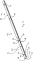
- ist eine perspektivische Ansicht eines Schließteils der in
Fig. 1 gezeigten Beschlaganordnung, das zur Befestigung an einem dem Fensterrahmen zugeordneten Blendrahmen ausgebildet ist. - Fig. 4A
- ist eine perspektivische Ansicht eines Verschluss-Elements der in
Fig. 1 gezeigten Beschlaganordnung unmittelbar vor einem Eingreifen in eine Aussparung des Schließteils gemäßFig. 3 . - Fig. 4B
- zeigt das Verschluss-Element gemäß
Fig. 4A beim Eingreifen in einen Einführungsabschnitt der Aussparung. - Fig. 4C
- zeigt das Verschluss-Element gemäß
Fig. 4A in Eingriff mit einem Verriegelungsabschnitt der Aussparung. - Fig. 5A
- zeigt die in
Fig. 4A dargestellte Anordnung zusammen mit einem Führungsbauteil in einer seitlichen Schnittansicht. - Fig. 5B
- zeigt die in
Fig. 4B dargestellte Anordnung zusammen mit einem Führungsbauteil in einer seitlichen Schnittansicht. - Fig. 5C
- zeigt die in
Fig. 4C dargestellte Anordnung zusammen mit einem Führungsbauteil in einer seitlichen Schnittansicht.
- Fig. 1
- is a partial perspective view of a window frame, which is provided with a fitting arrangement according to the invention, wherein an edge closure formed by the fitting arrangement is in a release state.
- Fig. 2
- shows the window frame according to
Fig. 1 , wherein the edge closure is in a locked state. - Fig. 3
- is a perspective view of a closing part of in
Fig. 1 shown fitting arrangement, which is designed for attachment to a window frame associated with the frame. - Fig. 4A
- is a perspective view of a closure element of in
Fig. 1 shown fitting arrangement immediately before engaging in a recess of the closing part according toFig. 3 , - Fig. 4B
- shows the closure element according to
Fig. 4A when engaging in an insertion portion of the recess. - Fig. 4C
- shows the closure element according to
Fig. 4A in engagement with a locking portion of the recess. - Fig. 5A
- shows the in
Fig. 4A illustrated arrangement together with a guide member in a side sectional view. - Fig. 5B
- shows the in
Fig. 4B illustrated arrangement together with a guide member in a side sectional view. - Fig. 5C
- shows the in
Fig. 4C illustrated arrangement together with a guide member in a side sectional view.
Der in
Im Stulp der Holme 12 ist jeweils eine Beschlagnut 14 ausgebildet, an deren Seitenwänden 16 jeweils als lang gestreckte Ansätze ausgebildete, nach innen in die Beschlagnuten 14 hineinragende Wandabschnitte 18 ausgebildet sind. Aufgrund der perspektivischen Darstellung ist in
In der Beschlagnut 14 des im Bild oberen Holms 12B ist ein Teil einer Beschlaganordnung 19 angebracht. Die Beschlaganordnung 19 umfasst eine Stulpschienenanordnung 21, die bei dem dargestellten Ausführungsbeispiel in drei separate Stulpschienen 23, 24, 25 unterteilt ist. Die drei Stulpschienen 23, 24, 25 sind entlang der Längserstreckung L der Beschlagnut 14 hintereinander angeordnet und bilden den äußeren Abschluss der Beschlagnut 14. Das heißt an dem Fensterrahmen 11 ist kein die Stulpschienenanordnung 21 überragendes oder überdeckendes Element der Beschlaganordnung 19 angebracht.In the
Die Stulpschienen 23, 24, 25 können jeweils seitliche Längskanten aufweisen, die zum zumindest bereichsweisen Hintergreifen der nach innen ragenden Wandabschnitte 18 der Beschlagnut 14 ausgebildet sind. Auf diese Weise sind die Stulpschienen 23, 24, 25 entlang der Längserstreckung L verschiebbar in der Beschlagnut 14 geführt, wobei ein Austreten der Stulpschienen 23, 24, 25 aus der Beschlagnut 14 quer zu der Längserstreckung L der Beschlagnut 14 unterbunden ist. Bei dem dargestellten Ausführungsbeispiel ist lediglich für die beiden äußeren Stulpschienen 23, 25 eine Verschiebbarkeit vorgesehen, während die mittlere Stulpschiene 24 unverschiebbar in der Beschlagnut 14 sitzt. Ein im Fensterrahmen 11 versenkt angeordnetes und daher in
An der im Bild linken Stulpschiene 23 sind zwei Verschluss-Elemente 27 gleitend verschiebbar gelagert. Die Verschieberichtung V verläuft hierbei rechtwinklig zu der Längserstreckung L der Beschlagnut 14. An der im Bild rechten Stulpschiene 25 sind in der gleichen Weise zwei Verschluss-Elemente gelagert, was in
Die Beschlaganordnung 19 umfasst außerdem mehrere ortsfest in der Beschlagnut 14 angeordnete Führungsbauteile 70, von denen eines in
In dem in
Wenn ein Benutzer ausgehend von dem in
Wenn sich die Stulpschienen 23, 25 in der Verriegelungsstellung gemäß
Insgesamt bilden die Führungskulissen 75 der Führungsbauteile 70 einen Steuermechanismus, welcher dafür sorgt, dass die Verschluss-Elemente 27 bei einem Betätigen des Griffs 26 zunächst in der Verschieberichtung V aus einer in die Stulpschiene 23 eingefahrenen Stellung in eine aus der Stulpschiene 23 ausgefahrene Stellung und anschließend in dem ausgefahrenen Zustand gemeinsam mit der Stulpschiene 23 entlang der Längserstreckung L der Beschlagnut 14 verschoben werden.Overall, the
Das in
Wie aus
Nachfolgend wird unter Bezugnahme auf die
Zum Öffnen des Fensterrahmens 11 dreht der Benutzer den Griff 26 ausgehend von der in
Dadurch dass die ausfahrbaren Verschluss-Elemente 27 an der verschiebbaren Stulpschiene 23, 25 gelagert sind, kann der Stulp des Fensterrahmens 11 besonders ansprechend gestaltet werden. Grundsätzlich könnte das in
- 1111
- Fensterrahmenwindow frame
- 12A, 12B12A, 12B
- HolmHolm
- 1313
- Verbindungseckejoint corner
- 1414
- Beschlagnutfitting groove
- 1616
- SeitenwandSide wall
- 1818
- Wandabschnittwall section
- 1919
- Beschlaganordnungfitting assembly
- 2121
- StulpschienenanordnungStulpschienenanordnung
- 2323
- äußere Stulpschieneouter faceplate
- 2424
- mittlere Stulpschienemiddle faceplate
- 2525
- äußere Stulpschieneouter faceplate
- 2626
- GriffHandle
- 2727
- Verschluss-ElementLock member
- 2929
- Pilzkopfmushroom head
- 3333
- Abschlussbauteilfinal part
- 3535
- Vorderseite des PilzkopfsFront side of the mushroom head
- 3737
- Oberseite der StulpschieneTop of the faceplate rail
- 3939
- Spaltgap
- 4141
- StangenausschlussRod-final
- 4545
- Schließteilclosing part
- 4747
- Vorderseitefront
- 4848
- Längskantelongitudinal edge
- 4949
- Rückseiteback
- 5151
- Profilelementprofile element
- 5353
- äußerer Teilouter part
- 5555
- Aussparungrecess
- 5757
- Einführungsabschnittintroduction section
- 5959
- Verriegelungsabschnittlocking section
- 6060
- Klappeflap
- 7070
- Führungsbauteilguiding member
- 7575
- Führungskulisseguide link
- 7777
- erster Verschiebeabschnittfirst displacement section
- 7979
- Ausfahrabschnittextension leg
- 8181
- zweiter Verschiebeabschnittsecond displacement section
- LL
- Längserstreckung der BeschlagnutLongitudinal extension of the fitting groove
- VV
- Verschieberichtungdisplacement direction
- RR
- Rotationsachseaxis of rotation
Claims (15)
- A fitting arrangement (19) for windows, doors or the like, in particular for plastic windows or plastic doors, having at least one cover rail (23, 25) for at least regionally covering a fitting groove (14) which is formed in a frame or in a leaf frame (11) of the window, of the door or the like; having at least one closure element (27) which is movable between a release position and a latched position along a longitudinal extent (L) of the fitting groove (14); and having a gear which can be actuated to move the closure element (27), wherein
the cover rail (23, 25) is configured for a support in the fitting groove (14) displaceable along the longitudinal extent (L) and the at least one closure element (27) is displaceably supported at the cover rail (23, 25) in and against an extension direction (V) running transversely to the longitudinal extent (L),
characterized in that
a control mechanism (75) of the fitting arrangement (19) in an assembled state thereof ensures that, on an actuation of a drive section, the closure element (27) is first displaced in the extension direction (V) from a position retracted into the cover rail (23, 25) into a position extended from the cover rail (23, 25) and is subsequently, in an extended state, displaced together with the cover rail (23, 25) along the longitudinal extent (L) of the fitting groove (14) in order to move from the release position into the latched position. - A fitting arrangement in accordance with claim 1,
characterized in that
the closure element (27) is linearly displaceably supported at the cover rail (23, 25), in particular by means of a sliding support. - A fitting arrangement in accordance with claim 1 or claim 2,
characterized in that
the closure element (27) is recessed in the cover rail (23, 25) in the retracted position, in particular with
the closure element (27) not projecting beyond an upper side (37) of the cover rail (23, 25) facing outwardly with respect to the fitting groove (14) in the retracted position, and in particular with the closure element (27) having a planar end face (35) which is at least substantially in alignment with the upper side (37) of the cover rail (23, 25) when the closure element (27) is located in the retracted position. - A fitting arrangement in accordance with any one of the preceding claims,
characterized in that
the cover rail (23, 25) is not covered by a further element of the fitting arrangement (19); and/or in that
the cover rail (23, 25) has lateral longitudinal edges which are configured for an at least regional engagement behind of wall sections (18) of the fitting groove (14) which project inwardly from two oppositely disposed side walls (16) of the fitting groove (14). - A fitting arrangement in accordance with any one of the preceding claims,
characterized in that
the control mechanism comprises a slot guide (75) which is arranged in a fixed position in the fitting groove (14) in the assembled state of the fitting arrangement (19) and in which the closure element (27) is guided, with the slot guide (75) comprising at least one extension section (79) which extends obliquely with respect to the longitudinal extent (L) of the fitting groove (14) in the assembled state of the fitting arrangement (19), and in particular with the slot guide (75) comprising a displacement section (81) which adjoins the extension section (79) and which extends in parallel with the longitudinal extent (L) of the fitting groove (14) in the assembled state of the fitting arrangement (19). - A fitting arrangement in accordance with claim 5,
characterized in that
the slot guide (75) is formed at a guide component (70) which is configured for introduction into the fitting groove (14) from its end side, in particular with the guide component (70) being fastenable in the fitting groove (14) by means of a latch connection or a clip connection. - A fitting arrangement in accordance with any one of the preceding claims,
characterized in that
the closure element (27) is configured as an elongate latch pin whose pin axis at least substantially extends in the extension direction (V), in particular with
the latch pin having a mushroom head (29); and/or in that the drive section is rotationally actuable, with the closure element (27) being movable from the retracted position into the extended position by a rotation of the drive section starting from a basic position about a first angle of rotation, for example about 45°, and being movable from the release position into the latched position by a further rotation of the drive section about a second angle of rotation, for example about a further 45°. - A window, a door or the like, in particular a plastic window or a plastic door, having a frame or a leaf frame (11) in which at least one fitting groove (14) is formed which has two oppositely disposed side walls (16) comprising respective inwardly projecting wall sections (18), wherein the cover rail (23, 24, 25) at least regionally engages behind the inwardly projecting wall sections (18) such that an escape of the cover rail (23, 24, 25) from the fitting groove (14) in a direction running transversely to the longitudinal extent (L) of the fitting groove (14) is prevented; and having a fitting arrangement (19) in accordance with any one of the preceding claims.
- A fitting arrangement (19) in accordance with any one of the claims 1 to 7,
characterized by
a striker plate (45) which is configured for fastening to a frame or to a leaf frame of the window, of the door or the like and which has a reception opening for receiving a closure element (27), such as a latch pin, which is displaceably supported at the other one of the frame and leaf frame, with the striker plate being configured as an elongate rail (45) which has a cut-out (55) forming the reception opening. - A fitting arrangement in accordance with claim 9,
characterized in that
the cut-out (55) is only open toward a front side of the rail (45) which, in an assembled state of the striker plate, is formed at the side of the rail (45) remote from a side surface of the frame or of the leaf frame, in particular with
the front side (47) of the rail (45) defining an at least substantially closed surface with the exception of the cut-out (55). - A fitting arrangement in accordance with claim 9 or claim 10,
characterized in that
the rail (45) extends over at least 50% and preferably over at least 75% of the total length of a fitting groove (14) of the frame or of the leaf frame in the assembled state; and/or in that the rail (45) has a total length of at least 30 cm; and/or in that the cut-out (55) has an introduction section (57) and a latching section (59) narrowed with respect to the introduction section (57), in particular with the cut-out (55) having the shape of a keyhole. - A fitting arrangement in accordance with any one of the claims 9 to 11,
characterized in that
the cut-out (55) can be closed by a movable cover (60), in particular by a pivotable flap, in particular with
the movable cover (60) being preloaded into a closed position by a spring device. - A fitting arrangement in accordance with any one of the claims 9 to 12,
characterized in that
the striker plate is divided into a plurality of separate rail parts, in particular three separate rail parts, along its rail longitudinal axis; and/or in that the striker plate has a plurality of cut-outs (55) which are arranged distributed along its rail longitudinal axis. - A window, a door or the like, in particular a plastic window or a plastic door, having a frame or a leaf frame; and having a fitting arrangement in accordance with any one of the claims 9 to 13.
- A window, a door or the like in accordance with claim 14,
characterized in that
the striker plate extends over at least 50% and preferably over at least 75% of the total length of a fitting groove (14) of the frame or of the leaf frame; and/or in that
the striker plate extends over at least 50% and preferably over at least 75% of a side of the frame or of the leaf frame.
Applications Claiming Priority (2)
| Application Number | Priority Date | Filing Date | Title |
|---|---|---|---|
| DE102014115447.9A DE102014115447A1 (en) | 2014-10-23 | 2014-10-23 | fitting assembly |
| PCT/EP2015/073803 WO2016062595A1 (en) | 2014-10-23 | 2015-10-14 | Fitting arrangement |
Publications (2)
| Publication Number | Publication Date |
|---|---|
| EP3194697A1 EP3194697A1 (en) | 2017-07-26 |
| EP3194697B1 true EP3194697B1 (en) | 2019-06-05 |
Family
ID=54325543
Family Applications (1)
| Application Number | Title | Priority Date | Filing Date |
|---|---|---|---|
| EP15781076.3A Active EP3194697B1 (en) | 2014-10-23 | 2015-10-14 | Fitting arrangement |
Country Status (3)
| Country | Link |
|---|---|
| EP (1) | EP3194697B1 (en) |
| DE (1) | DE102014115447A1 (en) |
| WO (1) | WO2016062595A1 (en) |
Family Cites Families (7)
| Publication number | Priority date | Publication date | Assignee | Title |
|---|---|---|---|---|
| FR320287A (en) * | 1902-04-08 | 1902-12-06 | Vegh Et Triay Soc | Automatic occluder for strikes of locks and bolts |
| AT7064U1 (en) * | 2003-01-16 | 2004-09-27 | Kaba Gege Gmbh | LOCKING PIECE FOR A MULTI-LOCK LOCK |
| EP1593807B1 (en) * | 2004-05-03 | 2016-12-07 | Buva Rationele Bouwprodukten Bv | Window assembly |
| DE102008025444A1 (en) | 2008-05-28 | 2009-12-03 | Mayer & Co. | Plastic window or door and method of making the same |
| DE202008015517U1 (en) * | 2008-11-22 | 2009-02-26 | Carl Fuhr Gmbh & Co. Kg | Locking strip for a locking system with multiple locking |
| DE102008062950A1 (en) * | 2008-12-23 | 2010-06-24 | Roto Frank Ag | Fitting with retractable locking element |
| US8939474B2 (en) * | 2011-06-03 | 2015-01-27 | Amesbury Group, Inc. | Lock with sliding locking elements |
-
2014
- 2014-10-23 DE DE102014115447.9A patent/DE102014115447A1/en not_active Withdrawn
-
2015
- 2015-10-14 WO PCT/EP2015/073803 patent/WO2016062595A1/en active Application Filing
- 2015-10-14 EP EP15781076.3A patent/EP3194697B1/en active Active
Non-Patent Citations (1)
| Title |
|---|
| None * |
Also Published As
| Publication number | Publication date |
|---|---|
| EP3194697A1 (en) | 2017-07-26 |
| WO2016062595A1 (en) | 2016-04-28 |
| DE102014115447A1 (en) | 2016-04-28 |
Similar Documents
| Publication | Publication Date | Title |
|---|---|---|
| EP1437471B1 (en) | Fitting for a lifting and sliding door or a lifting and sliding window | |
| EP2692969B1 (en) | Gear of a drive rod fixture, drive rod fixture with such a gear and window, door or similar with such a drive rod fixture | |
| DE202022100517U1 (en) | Profile arrangement of a window or a door with a casement profile, in particular a sliding casement profile | |
| DE10219692A1 (en) | Lock fitting on a window, eienr door or the like, with oppositely displaceable drive rods | |
| EP1462594B1 (en) | Gear mechanism, in particular mortise gear mechanism for a window or similar | |
| AT500183B1 (en) | REVERSIBLE CLOSURE FOR WINDOWS, DOORS OR THE LIKE | |
| EP0844348B1 (en) | Hinge for doors or windows | |
| EP1159502B1 (en) | Window or door | |
| EP3715578A1 (en) | Insect proof door | |
| EP3371397B1 (en) | Fitting assembly | |
| EP3194697B1 (en) | Fitting arrangement | |
| DE202022100516U1 (en) | Displacement device for forced displacement of a leaf, in particular a sliding leaf, a window or a door | |
| EP0945579A2 (en) | Ventilation device | |
| EP1076140B1 (en) | Closure actuator for the wings of windows, doors or the like, particularly for sliding wings | |
| EP3350394B1 (en) | Operating bar fitting | |
| EP0980951A2 (en) | Fitting for adjustable-in-parallel and subsequently slidable windows, doors or the like | |
| DE102006035416A1 (en) | Closure for drive rod fitting of flank of window locked in frame or window door, has stationary closing plate and closing pin, which is arranged on connecting rod guided in longitudinally displaced manner | |
| EP3018269B1 (en) | Handle assembly for a window or the like and window or the like with handle assembly | |
| EP1179110A1 (en) | Lock bar mounting for a window or door | |
| DE202013103537U1 (en) | Device for locking and unlocking a window sash, a ventilation flap or the like on a window frame | |
| EP1659241B1 (en) | Burglar-proof fitting for a multi-light window or multi-leaf door | |
| EP3189199B1 (en) | Fitting arrangement | |
| EP3444417B1 (en) | Load system for building openings | |
| DE202022104654U1 (en) | Profile arrangement of a window or a door with a casement profile, in particular a sliding casement profile | |
| DE29800306U1 (en) | Fitting for a casement of windows or doors |
Legal Events
| Date | Code | Title | Description |
|---|---|---|---|
| STAA | Information on the status of an ep patent application or granted ep patent |
Free format text: STATUS: THE INTERNATIONAL PUBLICATION HAS BEEN MADE |
|
| PUAI | Public reference made under article 153(3) epc to a published international application that has entered the european phase |
Free format text: ORIGINAL CODE: 0009012 |
|
| STAA | Information on the status of an ep patent application or granted ep patent |
Free format text: STATUS: REQUEST FOR EXAMINATION WAS MADE |
|
| 17P | Request for examination filed |
Effective date: 20170419 |
|
| AK | Designated contracting states |
Kind code of ref document: A1 Designated state(s): AL AT BE BG CH CY CZ DE DK EE ES FI FR GB GR HR HU IE IS IT LI LT LU LV MC MK MT NL NO PL PT RO RS SE SI SK SM TR |
|
| AX | Request for extension of the european patent |
Extension state: BA ME |
|
| DAV | Request for validation of the european patent (deleted) | ||
| DAX | Request for extension of the european patent (deleted) | ||
| GRAP | Despatch of communication of intention to grant a patent |
Free format text: ORIGINAL CODE: EPIDOSNIGR1 |
|
| STAA | Information on the status of an ep patent application or granted ep patent |
Free format text: STATUS: GRANT OF PATENT IS INTENDED |
|
| INTG | Intention to grant announced |
Effective date: 20181221 |
|
| GRAS | Grant fee paid |
Free format text: ORIGINAL CODE: EPIDOSNIGR3 |
|
| GRAA | (expected) grant |
Free format text: ORIGINAL CODE: 0009210 |
|
| STAA | Information on the status of an ep patent application or granted ep patent |
Free format text: STATUS: THE PATENT HAS BEEN GRANTED |
|
| AK | Designated contracting states |
Kind code of ref document: B1 Designated state(s): AL AT BE BG CH CY CZ DE DK EE ES FI FR GB GR HR HU IE IS IT LI LT LU LV MC MK MT NL NO PL PT RO RS SE SI SK SM TR |
|
| REG | Reference to a national code |
Ref country code: GB Ref legal event code: FG4D Free format text: NOT ENGLISH |
|
| REG | Reference to a national code |
Ref country code: CH Ref legal event code: EP |
|
| REG | Reference to a national code |
Ref country code: AT Ref legal event code: REF Ref document number: 1140130 Country of ref document: AT Kind code of ref document: T Effective date: 20190615 |
|
| REG | Reference to a national code |
Ref country code: IE Ref legal event code: FG4D Free format text: LANGUAGE OF EP DOCUMENT: GERMAN |
|
| REG | Reference to a national code |
Ref country code: DE Ref legal event code: R096 Ref document number: 502015009249 Country of ref document: DE |
|
| REG | Reference to a national code |
Ref country code: NL Ref legal event code: MP Effective date: 20190605 |
|
| REG | Reference to a national code |
Ref country code: LT Ref legal event code: MG4D |
|
| PG25 | Lapsed in a contracting state [announced via postgrant information from national office to epo] |
Ref country code: NO Free format text: LAPSE BECAUSE OF FAILURE TO SUBMIT A TRANSLATION OF THE DESCRIPTION OR TO PAY THE FEE WITHIN THE PRESCRIBED TIME-LIMIT Effective date: 20190905 Ref country code: ES Free format text: LAPSE BECAUSE OF FAILURE TO SUBMIT A TRANSLATION OF THE DESCRIPTION OR TO PAY THE FEE WITHIN THE PRESCRIBED TIME-LIMIT Effective date: 20190605 Ref country code: LT Free format text: LAPSE BECAUSE OF FAILURE TO SUBMIT A TRANSLATION OF THE DESCRIPTION OR TO PAY THE FEE WITHIN THE PRESCRIBED TIME-LIMIT Effective date: 20190605 Ref country code: SE Free format text: LAPSE BECAUSE OF FAILURE TO SUBMIT A TRANSLATION OF THE DESCRIPTION OR TO PAY THE FEE WITHIN THE PRESCRIBED TIME-LIMIT Effective date: 20190605 Ref country code: HR Free format text: LAPSE BECAUSE OF FAILURE TO SUBMIT A TRANSLATION OF THE DESCRIPTION OR TO PAY THE FEE WITHIN THE PRESCRIBED TIME-LIMIT Effective date: 20190605 Ref country code: AL Free format text: LAPSE BECAUSE OF FAILURE TO SUBMIT A TRANSLATION OF THE DESCRIPTION OR TO PAY THE FEE WITHIN THE PRESCRIBED TIME-LIMIT Effective date: 20190605 Ref country code: FI Free format text: LAPSE BECAUSE OF FAILURE TO SUBMIT A TRANSLATION OF THE DESCRIPTION OR TO PAY THE FEE WITHIN THE PRESCRIBED TIME-LIMIT Effective date: 20190605 |
|
| PG25 | Lapsed in a contracting state [announced via postgrant information from national office to epo] |
Ref country code: LV Free format text: LAPSE BECAUSE OF FAILURE TO SUBMIT A TRANSLATION OF THE DESCRIPTION OR TO PAY THE FEE WITHIN THE PRESCRIBED TIME-LIMIT Effective date: 20190605 Ref country code: GR Free format text: LAPSE BECAUSE OF FAILURE TO SUBMIT A TRANSLATION OF THE DESCRIPTION OR TO PAY THE FEE WITHIN THE PRESCRIBED TIME-LIMIT Effective date: 20190906 Ref country code: BG Free format text: LAPSE BECAUSE OF FAILURE TO SUBMIT A TRANSLATION OF THE DESCRIPTION OR TO PAY THE FEE WITHIN THE PRESCRIBED TIME-LIMIT Effective date: 20190905 Ref country code: RS Free format text: LAPSE BECAUSE OF FAILURE TO SUBMIT A TRANSLATION OF THE DESCRIPTION OR TO PAY THE FEE WITHIN THE PRESCRIBED TIME-LIMIT Effective date: 20190605 |
|
| PG25 | Lapsed in a contracting state [announced via postgrant information from national office to epo] |
Ref country code: CZ Free format text: LAPSE BECAUSE OF FAILURE TO SUBMIT A TRANSLATION OF THE DESCRIPTION OR TO PAY THE FEE WITHIN THE PRESCRIBED TIME-LIMIT Effective date: 20190605 Ref country code: SK Free format text: LAPSE BECAUSE OF FAILURE TO SUBMIT A TRANSLATION OF THE DESCRIPTION OR TO PAY THE FEE WITHIN THE PRESCRIBED TIME-LIMIT Effective date: 20190605 Ref country code: RO Free format text: LAPSE BECAUSE OF FAILURE TO SUBMIT A TRANSLATION OF THE DESCRIPTION OR TO PAY THE FEE WITHIN THE PRESCRIBED TIME-LIMIT Effective date: 20190605 Ref country code: PT Free format text: LAPSE BECAUSE OF FAILURE TO SUBMIT A TRANSLATION OF THE DESCRIPTION OR TO PAY THE FEE WITHIN THE PRESCRIBED TIME-LIMIT Effective date: 20191007 Ref country code: NL Free format text: LAPSE BECAUSE OF FAILURE TO SUBMIT A TRANSLATION OF THE DESCRIPTION OR TO PAY THE FEE WITHIN THE PRESCRIBED TIME-LIMIT Effective date: 20190605 Ref country code: EE Free format text: LAPSE BECAUSE OF FAILURE TO SUBMIT A TRANSLATION OF THE DESCRIPTION OR TO PAY THE FEE WITHIN THE PRESCRIBED TIME-LIMIT Effective date: 20190605 |
|
| PG25 | Lapsed in a contracting state [announced via postgrant information from national office to epo] |
Ref country code: IT Free format text: LAPSE BECAUSE OF FAILURE TO SUBMIT A TRANSLATION OF THE DESCRIPTION OR TO PAY THE FEE WITHIN THE PRESCRIBED TIME-LIMIT Effective date: 20190605 Ref country code: IS Free format text: LAPSE BECAUSE OF FAILURE TO SUBMIT A TRANSLATION OF THE DESCRIPTION OR TO PAY THE FEE WITHIN THE PRESCRIBED TIME-LIMIT Effective date: 20191005 Ref country code: SM Free format text: LAPSE BECAUSE OF FAILURE TO SUBMIT A TRANSLATION OF THE DESCRIPTION OR TO PAY THE FEE WITHIN THE PRESCRIBED TIME-LIMIT Effective date: 20190605 |
|
| REG | Reference to a national code |
Ref country code: DE Ref legal event code: R026 Ref document number: 502015009249 Country of ref document: DE |
|
| PLBI | Opposition filed |
Free format text: ORIGINAL CODE: 0009260 |
|
| PG25 | Lapsed in a contracting state [announced via postgrant information from national office to epo] |
Ref country code: TR Free format text: LAPSE BECAUSE OF FAILURE TO SUBMIT A TRANSLATION OF THE DESCRIPTION OR TO PAY THE FEE WITHIN THE PRESCRIBED TIME-LIMIT Effective date: 20190605 |
|
| 26 | Opposition filed |
Opponent name: GEZE GMBH Effective date: 20200305 |
|
| PG25 | Lapsed in a contracting state [announced via postgrant information from national office to epo] |
Ref country code: DK Free format text: LAPSE BECAUSE OF FAILURE TO SUBMIT A TRANSLATION OF THE DESCRIPTION OR TO PAY THE FEE WITHIN THE PRESCRIBED TIME-LIMIT Effective date: 20190605 Ref country code: PL Free format text: LAPSE BECAUSE OF FAILURE TO SUBMIT A TRANSLATION OF THE DESCRIPTION OR TO PAY THE FEE WITHIN THE PRESCRIBED TIME-LIMIT Effective date: 20190605 |
|
| PLAX | Notice of opposition and request to file observation + time limit sent |
Free format text: ORIGINAL CODE: EPIDOSNOBS2 |
|
| PG25 | Lapsed in a contracting state [announced via postgrant information from national office to epo] |
Ref country code: MC Free format text: LAPSE BECAUSE OF FAILURE TO SUBMIT A TRANSLATION OF THE DESCRIPTION OR TO PAY THE FEE WITHIN THE PRESCRIBED TIME-LIMIT Effective date: 20190605 Ref country code: SI Free format text: LAPSE BECAUSE OF FAILURE TO SUBMIT A TRANSLATION OF THE DESCRIPTION OR TO PAY THE FEE WITHIN THE PRESCRIBED TIME-LIMIT Effective date: 20190605 |
|
| REG | Reference to a national code |
Ref country code: CH Ref legal event code: PL |
|
| PLBB | Reply of patent proprietor to notice(s) of opposition received |
Free format text: ORIGINAL CODE: EPIDOSNOBS3 |
|
| PG25 | Lapsed in a contracting state [announced via postgrant information from national office to epo] |
Ref country code: LU Free format text: LAPSE BECAUSE OF NON-PAYMENT OF DUE FEES Effective date: 20191014 Ref country code: LI Free format text: LAPSE BECAUSE OF NON-PAYMENT OF DUE FEES Effective date: 20191031 Ref country code: CH Free format text: LAPSE BECAUSE OF NON-PAYMENT OF DUE FEES Effective date: 20191031 |
|
| REG | Reference to a national code |
Ref country code: BE Ref legal event code: MM Effective date: 20191031 |
|
| PG25 | Lapsed in a contracting state [announced via postgrant information from national office to epo] |
Ref country code: BE Free format text: LAPSE BECAUSE OF NON-PAYMENT OF DUE FEES Effective date: 20191031 |
|
| PG25 | Lapsed in a contracting state [announced via postgrant information from national office to epo] |
Ref country code: IE Free format text: LAPSE BECAUSE OF NON-PAYMENT OF DUE FEES Effective date: 20191014 Ref country code: FR Free format text: LAPSE BECAUSE OF NON-PAYMENT OF DUE FEES Effective date: 20191031 |
|
| PG25 | Lapsed in a contracting state [announced via postgrant information from national office to epo] |
Ref country code: CY Free format text: LAPSE BECAUSE OF FAILURE TO SUBMIT A TRANSLATION OF THE DESCRIPTION OR TO PAY THE FEE WITHIN THE PRESCRIBED TIME-LIMIT Effective date: 20190605 |
|
| PG25 | Lapsed in a contracting state [announced via postgrant information from national office to epo] |
Ref country code: MT Free format text: LAPSE BECAUSE OF FAILURE TO SUBMIT A TRANSLATION OF THE DESCRIPTION OR TO PAY THE FEE WITHIN THE PRESCRIBED TIME-LIMIT Effective date: 20190605 Ref country code: HU Free format text: LAPSE BECAUSE OF FAILURE TO SUBMIT A TRANSLATION OF THE DESCRIPTION OR TO PAY THE FEE WITHIN THE PRESCRIBED TIME-LIMIT; INVALID AB INITIO Effective date: 20151014 |
|
| REG | Reference to a national code |
Ref country code: DE Ref legal event code: R100 Ref document number: 502015009249 Country of ref document: DE |
|
| PLCK | Communication despatched that opposition was rejected |
Free format text: ORIGINAL CODE: EPIDOSNREJ1 |
|
| PLBN | Opposition rejected |
Free format text: ORIGINAL CODE: 0009273 |
|
| STAA | Information on the status of an ep patent application or granted ep patent |
Free format text: STATUS: OPPOSITION REJECTED |
|
| PG25 | Lapsed in a contracting state [announced via postgrant information from national office to epo] |
Ref country code: MK Free format text: LAPSE BECAUSE OF FAILURE TO SUBMIT A TRANSLATION OF THE DESCRIPTION OR TO PAY THE FEE WITHIN THE PRESCRIBED TIME-LIMIT Effective date: 20190605 |
|
| 27O | Opposition rejected |
Effective date: 20220127 |
|
| PGFP | Annual fee paid to national office [announced via postgrant information from national office to epo] |
Ref country code: GB Payment date: 20231020 Year of fee payment: 9 |
|
| PGFP | Annual fee paid to national office [announced via postgrant information from national office to epo] |
Ref country code: DE Payment date: 20231020 Year of fee payment: 9 Ref country code: AT Payment date: 20231020 Year of fee payment: 9 |