EP1437471B1 - Fitting for a lifting and sliding door or a lifting and sliding window - Google Patents
Fitting for a lifting and sliding door or a lifting and sliding window Download PDFInfo
- Publication number
- EP1437471B1 EP1437471B1 EP04000038A EP04000038A EP1437471B1 EP 1437471 B1 EP1437471 B1 EP 1437471B1 EP 04000038 A EP04000038 A EP 04000038A EP 04000038 A EP04000038 A EP 04000038A EP 1437471 B1 EP1437471 B1 EP 1437471B1
- Authority
- EP
- European Patent Office
- Prior art keywords
- runner
- leaf
- sash
- groove
- casement
- Prior art date
- Legal status (The legal status is an assumption and is not a legal conclusion. Google has not performed a legal analysis and makes no representation as to the accuracy of the status listed.)
- Expired - Lifetime
Links
- 230000008878 coupling Effects 0.000 claims description 49
- 238000010168 coupling process Methods 0.000 claims description 49
- 238000005859 coupling reaction Methods 0.000 claims description 49
- 230000033001 locomotion Effects 0.000 claims description 11
- 239000002184 metal Substances 0.000 claims description 9
- 229910052751 metal Inorganic materials 0.000 claims description 9
- 239000004033 plastic Substances 0.000 claims description 7
- 229920003023 plastic Polymers 0.000 claims description 7
- 239000002023 wood Substances 0.000 claims description 5
- HCHKCACWOHOZIP-UHFFFAOYSA-N Zinc Chemical compound [Zn] HCHKCACWOHOZIP-UHFFFAOYSA-N 0.000 claims description 3
- 229910052725 zinc Inorganic materials 0.000 claims description 3
- 239000011701 zinc Substances 0.000 claims description 3
- 238000002347 injection Methods 0.000 claims description 2
- 239000007924 injection Substances 0.000 claims description 2
- 230000007704 transition Effects 0.000 claims description 2
- 230000002093 peripheral effect Effects 0.000 claims 1
- 230000005540 biological transmission Effects 0.000 description 11
- 238000004519 manufacturing process Methods 0.000 description 7
- 238000009434 installation Methods 0.000 description 5
- 239000000463 material Substances 0.000 description 4
- 230000008901 benefit Effects 0.000 description 3
- 230000009467 reduction Effects 0.000 description 3
- 238000007789 sealing Methods 0.000 description 3
- 235000003332 Ilex aquifolium Nutrition 0.000 description 2
- 241000209027 Ilex aquifolium Species 0.000 description 2
- 230000001154 acute effect Effects 0.000 description 2
- 230000015572 biosynthetic process Effects 0.000 description 2
- 230000008859 change Effects 0.000 description 2
- 238000006073 displacement reaction Methods 0.000 description 2
- 238000003801 milling Methods 0.000 description 2
- 238000012986 modification Methods 0.000 description 2
- 230000004048 modification Effects 0.000 description 2
- 229920000642 polymer Polymers 0.000 description 2
- 230000002787 reinforcement Effects 0.000 description 2
- QBWKPGNFQQJGFY-QLFBSQMISA-N 3-[(1r)-1-[(2r,6s)-2,6-dimethylmorpholin-4-yl]ethyl]-n-[6-methyl-3-(1h-pyrazol-4-yl)imidazo[1,2-a]pyrazin-8-yl]-1,2-thiazol-5-amine Chemical compound N1([C@H](C)C2=NSC(NC=3C4=NC=C(N4C=C(C)N=3)C3=CNN=C3)=C2)C[C@H](C)O[C@H](C)C1 QBWKPGNFQQJGFY-QLFBSQMISA-N 0.000 description 1
- 241001295925 Gegenes Species 0.000 description 1
- 241001236294 Hebe Species 0.000 description 1
- 240000006240 Linum usitatissimum Species 0.000 description 1
- 229910001229 Pot metal Inorganic materials 0.000 description 1
- 229910000639 Spring steel Inorganic materials 0.000 description 1
- 229910000831 Steel Inorganic materials 0.000 description 1
- 229940125846 compound 25 Drugs 0.000 description 1
- 238000010276 construction Methods 0.000 description 1
- 238000003745 diagnosis Methods 0.000 description 1
- 238000001125 extrusion Methods 0.000 description 1
- -1 for example Inorganic materials 0.000 description 1
- 238000001746 injection moulding Methods 0.000 description 1
- 230000002441 reversible effect Effects 0.000 description 1
- 239000010959 steel Substances 0.000 description 1
- 230000003313 weakening effect Effects 0.000 description 1
Images


Classifications
-
- E—FIXED CONSTRUCTIONS
- E05—LOCKS; KEYS; WINDOW OR DOOR FITTINGS; SAFES
- E05D—HINGES OR SUSPENSION DEVICES FOR DOORS, WINDOWS OR WINGS
- E05D15/00—Suspension arrangements for wings
- E05D15/56—Suspension arrangements for wings with successive different movements
- E05D15/565—Suspension arrangements for wings with successive different movements for raising wings before sliding
-
- E—FIXED CONSTRUCTIONS
- E05—LOCKS; KEYS; WINDOW OR DOOR FITTINGS; SAFES
- E05Y—INDEXING SCHEME RELATING TO HINGES OR OTHER SUSPENSION DEVICES FOR DOORS, WINDOWS OR WINGS AND DEVICES FOR MOVING WINGS INTO OPEN OR CLOSED POSITION, CHECKS FOR WINGS AND WING FITTINGS NOT OTHERWISE PROVIDED FOR, CONCERNED WITH THE FUNCTIONING OF THE WING
- E05Y2800/00—Details, accessories and auxiliary operations not otherwise provided for
-
- E—FIXED CONSTRUCTIONS
- E05—LOCKS; KEYS; WINDOW OR DOOR FITTINGS; SAFES
- E05Y—INDEXING SCHEME RELATING TO HINGES OR OTHER SUSPENSION DEVICES FOR DOORS, WINDOWS OR WINGS AND DEVICES FOR MOVING WINGS INTO OPEN OR CLOSED POSITION, CHECKS FOR WINGS AND WING FITTINGS NOT OTHERWISE PROVIDED FOR, CONCERNED WITH THE FUNCTIONING OF THE WING
- E05Y2900/00—Application of doors, windows, wings or fittings thereof
- E05Y2900/10—Application of doors, windows, wings or fittings thereof for buildings or parts thereof
- E05Y2900/13—Application of doors, windows, wings or fittings thereof for buildings or parts thereof characterised by the type of wing
- E05Y2900/132—Doors
-
- E—FIXED CONSTRUCTIONS
- E05—LOCKS; KEYS; WINDOW OR DOOR FITTINGS; SAFES
- E05Y—INDEXING SCHEME RELATING TO HINGES OR OTHER SUSPENSION DEVICES FOR DOORS, WINDOWS OR WINGS AND DEVICES FOR MOVING WINGS INTO OPEN OR CLOSED POSITION, CHECKS FOR WINGS AND WING FITTINGS NOT OTHERWISE PROVIDED FOR, CONCERNED WITH THE FUNCTIONING OF THE WING
- E05Y2900/00—Application of doors, windows, wings or fittings thereof
- E05Y2900/10—Application of doors, windows, wings or fittings thereof for buildings or parts thereof
- E05Y2900/13—Application of doors, windows, wings or fittings thereof for buildings or parts thereof characterised by the type of wing
- E05Y2900/148—Windows
Definitions
- the invention relates to a fitting for lift-slide doors or windows according to the preamble of claim 1 and to a lift-slide door or a lift-slide window according to the preamble of claim 15.
- Lifting and sliding doors or lifting and sliding windows as well as suitable fittings for these doors are known.
- the basic function of such doors or windows is that the respective door or window sash is raised and lowered relative to an outer floor frame and at the same time is displaceable in the wing plane, so that, for example, to open the closed wing this first raised in the vertical direction and then is shifted in the horizontal direction. In the reverse manner, the closing of the wing.
- lifting and sliding doors can also have a tilt function.
- U-shaped cuff rails are generally used in lifting-sliding doors or windows so far, which lead the respective drive rod slidably between their legs and are supported by the free edges of their legs at the bottom of the groove.
- the disadvantage here is that such U-shaped cuff rails are bulky, heavy and expensive and also require in the rebate a groove (Einbaunut) with a relatively large width, and that conditionally on the one hand by the additional material thickness of the legs and in particular also due to the fact that when using the manually operable transmission, the U-shaped face-plate has to overlap the housing of this transmission.
- Fittings are also known in which the corner drive consists of several lamellar spring steel strips arranged one above the other ( DE 34 40 505 ) or is formed by a chain ( DE 72 44 800 ).
- These embodiments have the disadvantage that the transmission of shear or compressive forces is insufficient and therefore the lowering of the door leaf must be supported by the weight of this wing at least for this reason. The latter affects, inter alia, the free design possibility of acting between the running shoe and the associated bearing element lifting curve.
- the object of the invention is to show a fitting (espagnolette fitting), which can be made particularly inexpensive in a reliable operation and also allows a reduction in the width and / or depth of the installation groove.
- a lift-slide door or a lift-and-slide window is designed according to claim 15.
- the faceplate of a fitting for lifting-sliding doors or windows is flat or flat-band-like design.
- the Eckumlenkung is formed by a rigid, rod-like or pressure and Switzerland Swissianon coupling piece, which is guided displaceably in the bearing element.
- a bell-like, two-armed lever and the associated disadvantages, in particular an additional manufacturing effort and a relatively large space requirement during installation, are thus avoided.
- rod-like or pressure and Switzerland Glanite training of the clutch gap this is able to transmit both tensile forces and compressive forces reliably on the running shoe.
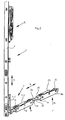
- FIG. 1 shows a building door, which consists in a conventional manner from the floor or window frame 1 and from the door provided in this frame 2, which formed as a lift-slide-wings, for example, with additional tilting function is, that can be raised or lowered for opening and closing in the vertical direction and is displaceable and tiltable.
- wing 2 or on the sash of the lifting and sliding fitting is provided in a known manner, which is generally denoted by 3 in the figures and, inter alia, attached to a vertical fold of the sash 2.1 faceplate 4, which there with a not shown Handle operable lifting gear 5 and on the face plate 4 axially displaceable (double arrow V) and driven by the transmission 5 drive rod 6 has. That in the Figures 2 . 3 and 4 lower end of the faceplate 4 is connected to a leg 7.1 of an angular bearing element 7, which is made of a suitable material, for example of plastic or metal.
- the bearing element 7 is connected to the leg 7.1, which is oriented in the mounted state of the fitting 3 in the vertical direction, with the face plate 4, for example by screws or rivets.
- the housing 8 is in the illustrated embodiment in one piece of a suitable material, for example of metal, e.g. manufactured as a metal injection molding (zinc injection molded part), with two extending in the longitudinal direction of the running shoe 2 parallel housing walls 10, which are connected to each other at the two ends of the housing by corresponding walls 11. Between the two ends, the walls 10 are still connected by additional stiffening walls 11.1.
- a suitable material for example of metal, e.g. manufactured as a metal injection molding (zinc injection molded part)
- rollers 12 are freely rotatably supported in the darg Congressen embodiment, namely about axes perpendicular to the plane of the door leaf 2.
- the rollers 12 are in a known manner with a at the bottom of the element Stock frame 1 provided rail 13 in engagement, which is also made of metal, for example.
- an oblique lifting cam is provided on the leg 7.2, in the form of an oblique, slot-like opening 14, which encloses an acute angle with the longitudinal extent of the leg 7.2.
- the opening 14 is provided on a projection 15 which is received between the walls 10, projects from the Matfl ügel adjacent side of the leg 7.2 in the housing 8 of the running shoe and lateral guide surfaces for the inner surfaces of the longitudinal walls 10 forms.
- a coupling piece 17 is provided which is rigidly designed as a pressure and Switzerland and formed in the illustrated embodiment as part of a ring.
- a circular arc-shaped guide is formed in the bearing element 7 in the region of the corner between the legs 7.1 and 7.2 of wall sections 18 and 19, a circular arc-shaped guide, in such a way that the coupling piece 17 in this guide on a circular arc about an axis perpendicular to the plane of the door leaf is movable (double arrow K).
- the coupling piece 17 is provided on its outer, ie convexly curved side with a plurality of teeth 20 forming a toothing.
- This gearing engages in openings 6.1 at the lower end of the drive rod 6, so that the axial movement of the drive rod 6 (double arrow V) the coupling piece 17th corresponding to the double arrow K performs a longitudinal movement in the form of a circular motion.
- the teeth 20 remote from the end of the coupling piece 17 is pivotally connected to the coupling piece adjacent this end of the running shoe 6, and in fact that the relevant end engages with a hook-like portion 21 in an opening 22.1 provided on the end wall 11 ⁇ senabitess 22.
- the coupling piece 17 engages with its portion 21 from above into the recess 22.1 of the eyelet portion 22 and engages behind an edge of the eyelet portion 22 with a rounded surface 21.1 formed on the portion 21.
- the training is further made such that the section 21 is guided at two in an axial direction perpendicular to the wing plane or parallel to the axis of rotation of the rollers 12 staggered side surfaces of surfaces within the recess 22.1, whereby the movements of the coupling piece 17 and the running shoe. 9 are stabilized when raising and lowering the door leaf 2.
- FIG. 4 shows the axis of the circular arc movement of the coupling piece 17 is within the angular space formed by the legs 7.1 and 7.2, and perpendicular to a plane which is defined by the longitudinal axes of these legs.
- the coupling piece 17 of the illustrated fitting 3 avoids the usual in lifting and sliding fittings pivotable deflection bell. This results in a very simple and reliable construction. Due to the formation of the coupling piece 17 at the one end as a circular arc-shaped toothed rack reliable drive connection between the drive rod 6 and the coupling piece 17 and the running shoe 9 is ensured, namely a driving connection through which both tensile forces for lifting the door, as Also shear forces for lowering the door leaf 2 can be effectively transferred. Another advantage of the deflection using the coupling piece 17 is that the bearing element 7 can be formed very small volume in the region of this deflection, which is therefore kept small for the installation in the door 2 required space.
- a further running shoe 24 is provided, in the region of the bearing element 7 remote second lower corner of the sash 2.1.
- the bearing element 23 is similar to the leg 7.2 of the bearing element 7 is formed.
- the running shoe 24 corresponds to the running shoe 9. Both running shoe 9 and 24 are connected in a known manner via a connecting member 25 with each other, which is suitable for the transmission of compressive and tensile forces.
- This connecting member 25 is, for example, a connecting rod, which is fastened at its ends to the running shoes 9 and 24, by engaging in sleeve-like coupling or connecting portions 26, the front of the respective shoe housing 8 and 8a, ie in the region of the end wall 11th are formed.
- the running shoe housing 8a of the running shoe 24 differs from the running shoe housing 8 only in that a coupling section 26 is located on both end walls 11 of the running shoe housing 8a.
- FIG. 7 shows the installation state of the bearing element 7 and the leg 7.2. This is taken up together with the running shoe 9 in a groove 27 provided on the underside of the door leaf. On both sides of the groove two extending over the entire width of this door leaf seals 28 are provided on the underside of the door, which bear against a sealing surface 13.1 of the track rail 13 when lowered, ie closed door 2.
- FIG. 8 shows in cross-section a connection 25 or connecting rod 25.1 with a circular cross-section and a connecting rod 25.2 with a square cross section, which can be used optionally as a compound 25.
- the cross sections of the two connecting rods are coordinated so that the diagnosis of the cross section of the square connecting rod 25.2 is slightly larger than the Druchmesser or twice the radius of the cross section of the connecting rod 25.1.
- the coupling section 26 integrally formed on the respective end of the running shoe housing 8 or 8a has an opening 29 whose cross-sectional shape initially corresponds to a square cross section, combined with a circular cross section in such a way that in that each of the four sides of the cross section has a circular cylindrical curved portion 30 corresponding to the circular cross section, and those portions 30 curved about the common center axis of the sleeve opening 29 are formed so as to obtain the corner portions 31 of the square cross section, ie there are perpendicular to adjacent surfaces.
- This means that the radius of curvature of the curved regions 30 is again smaller than half the distance between two diagonally opposite corner regions 31.
- the respective connecting rod 25.1 or 25.2 is inserted with one end into the opening 29 of a sleeve-like coupling portion 26 on the running shoe housing 8 and 8a and then provided with this coupling portion 26 locking means, for example Clamping screws 32 clamped.
- connecting rods 25.1 and 25.2 can be used on the market inexpensively available rod profiles made of metal, for example steel.
- the total cross section of these connecting rods can be kept relatively small, since in the case of use, the respective connection 25 or connecting rod 25.1 or 25.2 is essentially claimed only to train.
- the longitudinal extent of the respective lifting curve closes with the horizontal (axial direction of the double arrow H). an acute angle ⁇ , ie an angle ⁇ less than 90 ° ( Fig. 4 ), which opens in the running shoe 9 to the corner 7 and in the running shoe 24 from the running shoe 9 out.
- This course of the lift curve results in the tensile load in the connection 25 due to the weight of the door leaf 3. Compressive forces do not occur in this connection.
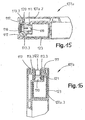
- FIG. 10-16 is designated 101 building door, which in turn has an outer floor or frame 102, provided in this frame fixed space 103 with the associated frame 104 and the associated glazing 105 and a wing 106 which is formed as a lifting and sliding wings.
- the wing 106 in turn, consists of the wing frame 107, which has the glazing 108 and is composed of four wing frame elements, which adjoin one another at right angles, from a sash profile, e.g. is made of wood, namely from the lower horizontal sash member 107.1, the opening or transmission side of the wing 106 forming vertical sash member 107.2, the upper horizontal sash member 107.3 and the other vertical sash member 107.4.
- a sash profile e.g. is made of wood
- the hand lever 109 having a gear 110 is provided, with which a provided in the fold of the sash frame 107 espagnolette u.a. a locking or unlocking of the wing 106 moved to the closed position is also possible on the frame 102 as well as the raising and lowering of the wing 106 for opening or closing.
- the wing 106 can be moved in the raised state parallel to its wing plane or parallel to the plane of the fixed field 103 in the horizontal direction.
- two running shoes or carriages 111 are provided in the illustrated embodiment at the lower horizontal sash member 107.1, which in the FIG. 10 only with their carriage rollers 112 schematically are indicated and which are guided with these rollers 112 in a horizontal guide rail.
- the two carriages 111 are formed with corresponding actuatable via the espagnolette lifting means.
- FIG. 11 shows a simplified representation of the lower, horizontal sash element 107.1 in a sash frame 107 made of wood.
- a groove 113 is introduced, which is open to the bottom of the sash member 107.1 out and lies in the illustrated embodiment with its center plane in the vertical center plane of the sash member 107.1.
- the groove 113 serves to receive the carriages 111, which are provided offset in this groove in the longitudinal direction of the sash member 107.1 against each other, but for the raising and lowering of the wing 106 are drivingly connected to each other.
- Each carriage 111 is attached to a carriage carrier 114 at the bottom 113.1 of the groove 113 in a suitable manner, for example by screwing.
- the carriage rollers 112 are freely rotatably mounted on a carriage or running shoe housing 115.
- the carriage housing 115 is connected for lifting and lowering of the wing 106 with the carriage carrier on the lifting means, which are formed in the simplest case of a lifting cam on the carriage carrier 114 and a cooperating with this lifting cam guide or sliding pin on the carriage housing 115.
- the depth of the groove 113 is selected so that, at least when the wing 106 is lowered, the carriages 111 with all their elements, including their carriage rollers 112, are almost completely received in the groove 113.
- the groove 113 is slightly widened, ie provided on both sides with a recess 116 so that each side surface 113.2 of the groove in the region of these recesses each forms a step with a surface 113.3, which lies in a plane perpendicular to the median plane of the groove 113 ,
- FIG. 12 shows a section through the vertical sash frame element 107.2 of the sash made of wood frame 107. Also in the sash member 107.2 is at the fold or at the closed wing 106 of the frame 102 adjacent outer side of the sash 107 again the groove 113 with the two recesses 116th and introduced with the additional grooves 117 for the seals.
- the groove 113 serves to attach the faceplate 118 of the aforementioned espagnolette fitting.
- the faceplate 118 is formed as a flat, band or strip-like (flat-band-like) rail and anchored via suitable fasteners 119 in the groove 113, in such a way that the faceplate 118 on its groove 113 facing side in an edge region of its longitudinal sides against the The recesses 116 formed surfaces 113.3 rests and covers the groove 113 to the outside.
- a likewise flat band-like drive rod 120 is slidably guided on the face plate 118 in the longitudinal direction.
- the drive rod 120 is drivingly connected to the gear 110 and controls, inter alia, via a not shown Eckumlenkung, as for example, those skilled in the DE 203 04 001 U is known, the carriage 111 for raising and lowering the wing 106th
- the flat band-like design of the faceplate 118 has, in addition to, in particular, a material and cost saving in particular also the advantage that the groove 113 at least outside of the recesses 116, ie over the greater part of their depth can be made relatively narrow, ie the groove width can be reduced from the current standard width of about 22 mm to about 16 mm, which at the same outer dimensions of the wood frame used for the sash 107 to a substantial increase in the strength of the sash 107 and thus u , a leads to an increase in burglar resistance, or allows a more compact design, in particular by reducing the dimensions of the profile used for the casement 107.
- FIG. 13 shows a section through the upper horizontal sash element.
- the groove 113 is provided with the two recesses 116, together with the provided on both sides of the groove 113 grooves 117 for the seal.
- an H-shaped profile 121 is inserted on the casement element 107.3 and secured in a suitable manner.
- a guide piece 122 is resiliently mounted in one piece, with which the wing 106 is guided on its upper side, ie with its sash element 107.3 on the frame 102 for raising and lowering and for moving.
- FIGS. 11-13 show is in all sash elements 107.1, 107.2 and 107.3 the local, necessary to accommodate the functional elements groove 113 formed identically, which also means a significant simplification and cost savings in manufacturing, since each same tools for the grooves 113 on all sash elements 107.1, 107.2 and 107.3 can be used.
- each groove 117 is located on a sash element 107.1 - 107.3 in a common plane with the corresponding groove on the other sash elements, so that the recorded in the grooves 117 of the sash elements 107.1 - 107.2 seals performed as a continuous seals can be and thus optimal sealing is achieved with the wing closed 106.
- FIGS. 14-16 show cuts similar to the FIGS. 12-13
- the sash elements 107a.1, 107a.2 and 107a.3 are each formed by a multi-chamber plastic profile with an internal metal reinforcement 123.
- the groove 113 with the two recesses 116 and with the contact surfaces 113.3 formed by these recesses and with the additional grooves 117 is again provided in all casement elements 107a.1, 107a.2 and 107a.3.
- the groove 113 again essentially serves to receive the two carriages 111, the casement element 107a.2 for receiving and fastening the flat-band-shaped cuff rail 118 with the drive rod 118 and the casement element 107a.3 for receiving the H profile 121 the guide piece 122.
Description
Die Erfindung bezieht sich auf einen Beschlag für Hebe-Schiebe-Türen oder -Fenster gemäß Oberbegriff Patentanspruch 1 sowie auf eine Hebe-Schiebe-Tür oder ein Hebe-Schiebe-Fenster gemäß Oberbegriff Patentanspruch 15.The invention relates to a fitting for lift-slide doors or windows according to the preamble of claim 1 and to a lift-slide door or a lift-slide window according to the preamble of
Hebe- und Schiebetüren oder Hebe- und Schiebefenster sowie geeignete Beschläge für diese Türen sind bekannt. Die grundsätzliche Funktion derartiger Türen oder Fenster ist, dass der jeweilige Tür- oder Fensterflügel relativ zu einem äußeren Stockrahmen anhebbar und absenkbar ist sowie zugleich auch in der Flügelebene verschiebbar ist, so dass beispielsweise zum Öffnen des geschlossenen Flügels dieser zunächst in vertikaler Richtung angehoben und dann in horizontaler Richtung verschoben wird. In umgekehrter Weise erfolgt das Schließen des Flügels. Als weitere Funktion können insbesondere Hebe- und Schiebetüren auch eine Kippfunktion haben.Lifting and sliding doors or lifting and sliding windows as well as suitable fittings for these doors are known. The basic function of such doors or windows is that the respective door or window sash is raised and lowered relative to an outer floor frame and at the same time is displaceable in the wing plane, so that, for example, to open the closed wing this first raised in the vertical direction and then is shifted in the horizontal direction. In the reverse manner, the closing of the wing. As a further function in particular lifting and sliding doors can also have a tilt function.
Bekannt ist auch, für das Anheben und Absenken an einem die Öffnungs- bzw. Schließseite des Flügels bildenden vertikalen Flügelrahmenelement ein manuell betätigbares Getriebe vorzusehen (
Zur Befestigung der Stulpschiene mit ihrer Treibstange sowie zur Aufnahme der Eckumlenkung und der Laufwagen, aber auch zur Unterbringung anderer Führungs- und Beschlagelemente sind am Umfang bzw, im Falz des Flügelrahmens Nuten (Einhaunuten) vorgesehen, die aber an den einzelnen Flügelrahmenelementen unterschiedlich ausgebildet sind.To attach the faceplate with its drive rod and to accommodate the corner and the carriage, but also to accommodate other management and fitting elements grooves (Einhaunuten) are provided on the periphery or in the fold of the sash, but which are formed differently on the individual sash elements.
Ein weiterer Nachteil dieses bekannten Beschlages ist aber, dass die von dem zweiarmigen Hebel gebildete Umlenkung einen relativ großen Einbauraum im Flügel erfordert, der durch eine entsprechend große Tiefe der Nut im Falzbereich (Einbaunut) geschaffen werden muss. Diese tiefe Einfräsung bedeutet u.a. eine Schwächung des Flügels und steht damit zumindest dem Erfordernis einer möglichst hohen Einbruchssicherheit entgegen.Another disadvantage of this known fitting is that the deflector formed by the two-armed lever requires a relatively large installation space in the wing, which must be created by a correspondingly large depth of the groove in the rebate (Einbaunut). This deep milling means i.a. a weakening of the wing and thus at least counteracts the requirement of the highest possible security against burglary.
Die unterschiedliche Ausbildung der Nuten an den Flügelrahmenelementen erfordert bei Flügelrahmen aus Holz die Verwendung unterschiedlicher Fräswerkzeuge bzw. einen entsprechenden Werkzeugwechsel, während bei Flügelrahmen aus Kunststoff für die Herstellung der Flügelrahmenprofile unterschiedliche Extrudierwerkzeuge notwendig sind, was den Herstellungsaufwand und die Herstellungskosten erhöht.The different design of the grooves on the wing frame elements requires the use of different milling tools or a corresponding tool change in wooden sash, while plastic sash for the production of sash profiles different extrusion tools are necessary, which increases the manufacturing cost and manufacturing costs.
Weiterhin werden bei Hebe-Schiebe-Türen oder -Fenstern bisher grundsätzlich im Querschnitt U-förmige Stulpschienen verwendet, die zwischen ihren Schenkeln die jeweilige Treibstange verschiebbar führen und sich mit den freien Rändern ihrer Schenkel am Boden der Nut abstützen. Nachteilig hierbei ist, dass derartige U-förmige Stulpschienen voluminös, schwer und teuer sind und darüber hinaus im Falzbereich eine Nut (Einbaunut) mit einer relativ großen Breite erfordern, und zwar bedingt einerseits durch die zusätzliche Materialstärke der Schenkel sowie insbesondere auch dadurch bedingt, dass bei Verwendung des manuell betätigbaren Getriebes die U-förmige Stulpschiene das Gehäuse dieses Getriebes übergreifen muss.Furthermore, U-shaped cuff rails are generally used in lifting-sliding doors or windows so far, which lead the respective drive rod slidably between their legs and are supported by the free edges of their legs at the bottom of the groove. The disadvantage here is that such U-shaped cuff rails are bulky, heavy and expensive and also require in the rebate a groove (Einbaunut) with a relatively large width, and that conditionally on the one hand by the additional material thickness of the legs and in particular also due to the fact that when using the manually operable transmission, the U-shaped face-plate has to overlap the housing of this transmission.
Bekannt sind weiterhin Beschläge, bei denen die Eckumlenkung aus mehreren lamellenartig übereinander angeordneten Federstahlbändern besteht (
Bekannt ist weiterhin, bei Hebe-Schiebe-Beschlägen das Laufwagen- oder Laufschuhgehäuse mehrteilig herzustellen, und zwar mit zwei Seitenblechen, wischen denen die Laufrollen des Laufschuhs drehbar gelagert sind. Diese Ausbildung bedeutet ebenfalls einen relativ großen Aufwand bei der Herstellung.It is also known in Hebe sliding fittings to make the carriage or running shoe housing in several parts, with two side plates, wipe which the rollers of the running shoe are rotatably mounted. This training also means a relatively large effort in the production.
Bekannt ist weiterhin ein Treibstangenbeschlag für Fenster oder Türen (
Aufgabe der Erfindung ist es, einen Beschlag (Treibstangenbeschlag) aufzuzeigen, der bei einer zuverlässigen Arbeitsweise besonders preiswert gefertigt werden kann und darüber hinaus eine Reduzierung der Breite und/oder Tiefe der Einbaunut ermöglicht.The object of the invention is to show a fitting (espagnolette fitting), which can be made particularly inexpensive in a reliable operation and also allows a reduction in the width and / or depth of the installation groove.
Zur Lösung dieser Aufgabe ist ein Beschlag entsprechend dem Patentanspruch 1 ausgebildet. Eine Hebe-Schiebe-Tür oder ein Hebe-Schiebe-Fenster ist entsprechend dem Patentanspruch 15 ausgeführt.To solve this problem, a fitting according to the patent claim 1 is formed. A lift-slide door or a lift-and-slide window is designed according to
Bei der Erfindung ist die Stulpschiene eines Beschlage für Hebe-Schiebe-Türen oder - Fenster flach bzw. flachbandartig ausgebildet.In the invention, the faceplate of a fitting for lifting-sliding doors or windows is flat or flat-band-like design.
Bei einer Ausführungsform der Erfindung ist die Eckumlenkung von einem starren, stangenartigen oder druck- und zugstückartigen Kupplungsstück gebildet, welches verschiebbar in dem Lagerelement geführt ist. Ein glockenartiger, zweiarmiger Hebel und die damit verbundenen Nachteile, insbesondere auch eines zusätzlichen Herstellungsaufwandes und eines relativ großen Platzbedarfes beim Einbau, sind somit vermieden. Durch die stangenartige oder druck- und zugstückartige Ausbildung des Kupplungsslückes ist dieses in der Lage sowohl Zugkräfte als auch Druckkräfte zuverlässig auf den Laufschuh zu übertragen.In one embodiment of the invention, the Eckumlenkung is formed by a rigid, rod-like or pressure and Zugstückartigen coupling piece, which is guided displaceably in the bearing element. A bell-like, two-armed lever and the associated disadvantages, in particular an additional manufacturing effort and a relatively large space requirement during installation, are thus avoided. By rod-like or pressure and Zugstückartige training of the clutch gap this is able to transmit both tensile forces and compressive forces reliably on the running shoe.
Zahlreiche weitere Ausführungen und Abwandlungen des Beschlages sind möglich, so ist es beispielweise möglich,
- dass das Kupplungsstück die Form eines Teilrings aufweist und derart im Lagerelement gelagert ist, dass die Ringsachse in einer Ebene senkrecht zur Türflügelebene liegt;
und/oder - dass das Kupplungsstück an seinem ersten Ende zahnstangenartig ausgebildet ist und mit diesem Ende mit einem gezahnten oder gelochten Abschnitt des Antriebselementes zusammenwirkt;
und/oder - dass das zweite Ende des Kupplungsstücks gelenkig mit dem Laufschuh oder einem Gehäuse des Laufschuhs verbunden ist;
und/oder - dass das Kupplungsstück mit seinem anderen Ende in eine Kupplungsöffnung des Laufschuhs oder des Laufschuhgehäuses eingreift; und/oder
- dass eine kreisbogenförmige Führung im Lagerelement für das Kupplungsstück vorgesehen ist,
und/oder - dass das Kupplungsstück als Formteil aus Metall oder Kunststoff gefertigt ist; und/oder
- daß das Kupplungsstück zumindest zwischen seinen beiden Enden einen von der Kreisform abweichenden Querschnitt, beispielsweise einen rechteckförmigen oder quadratischen Querschnitt aufweist;
und/oder - daß das Lagerelement als Winkelstück ausgebildet ist, und zwar mit zwei Schenkeln;
und/oder - daß an einem Schenkel das Antriebselement geführt ist und am anderen Ende der Laufschuh gelagert ist;
und/oder - daß das Kupplungsstück im Bereich des Übergangs zwischen beiden Schenkeln im Lagerelement vorgesehen ist;
und/oder - daß das Laufschuhgehäuse zwei sich in Laufschuhlängsrichtung erstreckende und voneinander beabstandete Wände aufweist, und daß zwischen den Wänden wenigstens zwei Laufrollen drehbar gelagert sind;
und/oder - daß die Längswände des Laufschuhgehäuses zumindest an den Enden des Laufschuhs durch stirnseitige Wände miteinander verbunden sind;
und/oder - daß am Lagerelement wenigstens ein eine Führung für den Laufschuh bildender Vorsprung vorgesehen ist;
und/oder - daß der wenigstens eine Vorsprung in das Laufschuhgehäuse hineinreicht und seitliche Führungsflächen für Innenflächen des Laufschuhgehäuses bildet;
und/oder - daß am Vorsprung wenigstens eine Hubkurve gebildet ist, mit der ein Führungsoder Gleitelement des Laufschuhs zusammenwirkt;
und/oder - daß die Hubkurve von einer Ausnehmung gebildet ist;
und/oder - daß das Gleitelement ein Führungsbolzen ist.
- that the coupling piece has the shape of a partial ring and is mounted in the bearing element such that the ring axis lies in a plane perpendicular to the door leaf level;
and or - that the coupling piece is formed at its first end rack-like and cooperates with this end with a toothed or perforated portion of the drive element;
and or - that the second end of the coupling piece is pivotally connected to the running shoe or a housing of the running shoe;
and or - that the coupling piece engages with its other end in a coupling opening of the running shoe or the running shoe housing; and or
- a circular-arc-shaped guide is provided in the bearing element for the coupling piece,
and or - that the coupling piece is made as a molded part made of metal or plastic; and or
- that the coupling piece has at least between its two ends a deviating from the circular cross-section, for example a rectangular or square cross-section;
and or - that the bearing element is formed as an angle piece, with two legs;
and or - that the drive element is guided on one leg and the running shoe is mounted on the other end;
and or - that the coupling piece is provided in the region of the transition between the two legs in the bearing element;
and or - that the running shoe housing has two extending in the longitudinal direction of the running and spaced walls, and that between the walls at least two rollers are rotatably mounted;
and or - that the longitudinal walls of the running shoe housing are connected to each other at least at the ends of the running shoe by frontal walls;
and or - that at least one guide for the running shoe forming projection is provided on the bearing element;
and or - that the at least one projection extends into the running shoe housing and forms lateral guide surfaces for inner surfaces of the running shoe housing;
and or - that at least one lift cam is formed on the projection, with which cooperates a guide or sliding element of the running shoe;
and or - that the lift curve is formed by a recess;
and or - that the sliding element is a guide pin.
Bei einer weiteren generellen Ausbildung der Erfindung ist das Gehäuse des jeweiligen Laufschuhs einstückig hergestellt, und zwar vorzugsweise aus einem Metalldruckguß, beispielsweise aus Zinkdruckguß. Hierdurch ergeben sich eine Reduzierung der Anzahl der Einzelteile des Beschlages sowie eine ganz erhebliche Reduzierung der Herstellungskosten. Bei dieser Ausführung ist das Gehäuse des Laufschuhs zusammen mit wenigstens einem an einem Ende des Laufschuhs vorgesehenen hülsenartiger Kupplungsabschnitt einstückig hergestellt, wobei. weitere möglichen Abwandlungen oder Ausführungsformen z.B. darin bestehen,
- daß der hülsenartige Kupplungsabschnitt eine Hülsenöffnung mit einem Querschnitt aufweist, der sich aus einer quadratischen Querschnittsform und einer kreisförmigen Querschnittsform derart zusammensetzt, daß er vier Seiten mit jeweils einem kreiszylinderförmigen Abschnitt und vier Eckbereiche mit rechtwinklig aneinander anschließenden Flächen bildet, wobei die kreiszylinderförmigen Abschnitte auf einer gemeinsamen, gedachten Kreiszylinderfläche um die Mitteilachse der Hülsenöffnung vorgesehen sind und der Radius der kreiszylinderförmigen Abschnitte etwas kleiner ist als der halbe Abstand zweier sich diagonal gegenüberliegender Eckbereiche, so daß der jeweilige hülsenartige Kupplungsabschnitt wahlweise für eine Verbindungsstange mit kreisförmigem oder quadratischem Querschnitt verwendbar ist;
und/oder - Mittel zum Fixieren der jeweiligen Verbindungsstange in der Hülsenöffnung
vorgesehen sind.
- that the sleeve-like coupling portion has a sleeve opening with a cross section which is composed of a square cross-sectional shape and a circular cross-sectional shape such that it forms four sides, each with a circular cylindrical portion and four corner regions with perpendicular adjoining surfaces, wherein the circular cylindrical portions on a common imaginary circular cylindrical surface are provided around the Mitteilachse the sleeve opening and the radius of the circular cylindrical portions is slightly smaller than half the distance between two diagonally opposite corner regions, so that the respective sleeve-like coupling portion is selectively usable for a connecting rod with a circular or square cross-section;
and or - Means for fixing the respective connecting rod in the sleeve opening
are provided.
Eine Hebe-Schiebe-Tür oder ein Hebe-Schiebe -Fenster gemäß der Erfindung, bei der bzw. bei dem die Stulpschiene als flache bzw. flachbandartige Schiene ausgebildet ist, ist z.B. so ausgeführt,
- daß die Treibstange flach bzw. flachbandartig ausgebildet ist;
und/oder - daß die Breite der Stulpschiene etwas größer ist als die Breite der Treibstange;
und/oder - daß die Nut zur Befestigung der Stulpschiene an ihrer Öffnung oder an ihrem Öffnungsrand beidseitig mit jeweils einer Aussparung versehen ist, die eine Anlagefläche bildet, gegen die die Stulpschiene mit Randbereichen anliegt, und daß die Treibstange in der Nut aufgenommen ist;
und/oder - daß die Nut eine Breite aufweist, die gleich oder annähernd gleich der Breite der Treibstange ist;
und/oder - daß zumindest die Nut zur Aufnahme der Laufwagen oder Laufschuhe und die Nut zur Befestigung der Stulpschiene mit Treibstange identisch ausgebildet sind;
und/oder - daß zumindest ein weiteres den Flügelrahmen bildendes Flügelrahmenelement, vorzugsweise ein die Oberseite des Flügels bildendes Flügelrahmenelement ebenfalls eine Nut aufweist, die identisch mit der Nut zur Aufnahme der Laufwagen oder Laufschuhe und mit der Nut zur Befestigung der Stulpschiene mit Treibstange ausgebildet ist;
und/oder - daß in der Nut des die Oberseite des Flügelrahmens bildenden Flügelrahmenelementes ein Profil mit Führungselement oder Führungsstück vorgesehen ist;
und/oder - daß die den Flügelrahmen bildenden Flügelrahmenelemente Profile aus Holz sind;
und/oder - daß die den Flügelrahmen bildenden Flügelrahmenelemente Profile aus Kunststoff sind.
- that the drive rod is flat or flat band-like;
and or - that the width of the faceplate rail is slightly larger than the width of the drive rod;
and or - that the groove for fixing the face-plate at its opening or at its opening edge is provided on both sides with a respective recess which forms a contact surface against which the face-plate abuts with edge regions, and that the drive rod is received in the groove;
and or - that the groove has a width which is equal to or approximately equal to the width of the drive rod;
and or - that at least the groove for receiving the carriage or running shoes and the groove for fixing the face plate with drive rod are identical;
and or - that at least one further sash frame element forming the sash frame, preferably a sash frame element forming the upper side of the sash, likewise has a groove which is identical to the groove for receiving the carriages or running shoes and to the groove for fastening the face plate with drive rod;
and or - that in the groove of the top of the sash frame forming sash element a profile with guide element or guide piece is provided;
and or - that the wing frame forming wing frame elements are wooden profiles;
and or - in that the sash frames forming wing frame elements are made of plastic.
Die Erfindung wird im Folgenden anhand der Figuren an einem Ausführungsbeispiel erläutert. Es zeigen:
- Fig. 1
- in Teildarstellung und in Frontansicht eine Hebe-Schiebe-Tür;
- Fig. 2
- in Einzeldarstellung den Hebe-Schiebe-Beschlag für die Tür der
Figur 1 ; - Fig. 3
- in perspektivischer Darstellung den
Beschlag der Figur 2 im Bereich der Eckumlenkung; - Fig. 4
- den
Beschlag der Figur 2 im Bereich der Eckumlenkung allerdings im Schnitt; - Fig. 5 und 6
- in verschiedener perspektivischer Ansicht das einstückig aus Zinkdruckguß hergestellte Laufschuhgehäuse der Laufschuhe des Beschlages der
Figur 1 ; - Fig. 7
- einen Schnitt durch den unteren Holm eines Flügelrahmens im Bereich eines Laufwagens;
- Fig. 8
- Querschnitte von Verbindungsstangen zum Verbinden zweier Lauffschuhe, und zwar mit kreisförmiger bzw. quadratischer Querschnittsform;
- Fig. 9
- einen Schnitt durch ein an einem Laufschuhgehäuse angeformten Kupplungsabschnitt zur wahlweisen Verwendung einer Verbindungsstange mit kreisförmiger oder quadratischer Querschnittsform;
- Fig. 10
- in vereinfachter Darstellung nochmals eine Gebäudetür mit einem Hebe- Schiebe-Flügel und einem Festfeld;
- Fig. 11
- einen Teilschnitt durch den unteren, horizontalen Holm bzw. das untere Flügelrahmenelement des Flügels entsprechend der Schnittlinie I -
I der Figur 10 bei einem Flügelrahmen aus Holz; - Fig. 12
- einen Schnitt durch das getriebeseitige vertikale Flügelrahmenelement des Flügels entsprechend der Linie II -
II der Figur 10 bei einem Flügelrahmen aus Holz; - Fig. 13
- einen Schnitt durch das obere horizontale Flügelrahmenelement des Flügels entsprechend der Linie III -
III der Figur 10 bei einem Flügelrahmen aus Holz; - Fig. 14 - 16
- Schnitte entsprechend den
Figuren 11 - 13 , jedoch bei einem Flügelrahmen aus einem Kunststoffprofil.
- Fig. 1
- in partial view and in front view of a lift-slide door;
- Fig. 2
- in a separate view the lifting-sliding fitting for the door of the
FIG. 1 ; - Fig. 3
- in perspective view of the fitting of
FIG. 2 in the field of cornering; - Fig. 4
- the fitting of the
FIG. 2 in the area of the corner deflection, however, on average; - FIGS. 5 and 6
- in a different perspective view, the one piece made of zinc die-cast running shoe housing of the running shoes of the fitting
FIG. 1 ; - Fig. 7
- a section through the lower spar of a sash in the area of a carriage;
- Fig. 8
- Cross sections of connecting rods for connecting two Lauffschuhe, with a circular or square cross-sectional shape;
- Fig. 9
- a section through an integrally formed on a shoe housing coupling portion for selectively using a connecting rod with a circular or square cross-sectional shape;
- Fig. 10
- in a simplified representation again a building door with a lift-slide wing and a fixed field;
- Fig. 11
- a partial section through the lower, horizontal spar or the lower sash element of the wing according to the section line I - I of
FIG. 10 in a wooden sash; - Fig. 12
- a section through the transmission-side vertical wing frame element of the wing according to the line II - II of
FIG. 10 in a wooden sash; - Fig. 13
- a section through the upper horizontal sash element of the wing according to the line III - III of
FIG. 10 in a wooden sash; - Fig. 14 - 16
- Cuts according to the
FIGS. 11-13 , but in a sash made of a plastic profile.
Die
Am Flügel 2 bzw. an dessen Flügelrahmen ist in bekannter Weise der Hebe- und Schiebe-Beschlag vorgesehen, der in den Figuren allgemein mit 3 bezeichnet ist und u.a. die an einem vertikalen Falz des Flügelrahmens 2.1 befestigte Stulpschiene 4, das dortige mit einem nicht dargestellten Handgriff betätigbare Hebegetriebe 5 und die an der Stulpschiene 4 axial verschiebbare (Doppelpfeil V) und von dem Getriebe 5 angetriebene Treibstange 6 aufweist. Das in den
Das Lagerelement 7 ist an dem Schenkel 7.1, der im montierten Zustand des Beschlages 3 in vertikaler Richtung orientiert ist, mit der Stulpschiene 4 verbunden, und zwar beispielsweise durch Schrauben oder Nieten. Ein weiterer Schenkel 7.2 des Lagerelementes 7, der bei montiertem Beschlag 3 am unteren horzontalen Holm des Türflügelrahmens 2.1 vorgesehen ist, bildet das Lager für das Gehäuse 8 eines Laufschuhs 9.The
Das Gehäuse 8 ist bei der dargestellten Ausführungsform einstückig aus einem geeigneten Material, beispielsweise aus Metall, z.B. als Metallspritzgußteil (Zinkspritzgußteil) hergestellt, und zwar mit zwei sich in Längsrichtung des Laufschuhs 2 erstreckenden parallelen Gehäusewänden 10, die an den beiden Enden des Gehäuses durch entsprechende Wandungen 11 miteinander verbunden sind. Zwischen den beiden Enden sind die Wände 10 noch durch zusätzliche Versteifungswände 11.1 miteinander verbunden.The
Im Gehäuse 8 sind bei der dargstellten Ausführungsform zwei Laufrollen 12 frei drehbar gelagert, und zwar um Achsen senkrecht zur Ebene des Türflügels 2. Die Laufrollen 12 stehen in bekannter Weise mit einer am unteren Element des Stockrahmens 1 vorgesehenen Laufschiene 13 in Eingriff, die beispielsweise ebenfalls aus Metall gefertigt ist.In the
Für das Anheben und Absenken des Türflügels 2 ist am Schenkel 7.2 eine schräge Hubkurve vorgesehen, und zwar in Form einer schräg verlaufenden, langlochartigen Öffnung 14, die mit der Längserstreckung des Schenkels 7.2 einen spitzen Winkel einschließt. Die Öffnung 14 ist an einem Vorsprung 15 vorgesehen, der zwischen den Wänden 10 aufgenommen ist, von der dem Türfl ügel benachbarten Seite des Schenkels 7.2 in das Gehäuse 8 des Laufschuhs hineinragt und seitliche Führungsflächen für die Innenflächen der Längswände 10 bildet. Durch den zwischen den beiden Wänden 10 aufgenommenen Vorsprung 15 ist der Laufschuh 9 eindeutig an dem Lagerelement 7 geführt. In die Öffnung 14 greift ein diese Wände 10 verbindender Führungsbolzen 16 ein.For raising and lowering the
Durch axiales Verschieben (Doppelpfeil H) des Laufschuhs 8 relativ zu dem Lagerelement 7 erfolgt das Anheben und Absenken des Türflügels 2. Dieses Verschieben erfolgt über die Treibstange 6 durch manuelles Betätigen des Getriebes 5. Für die antriebsmäßige Verbindung zwischen der Treibstange 6 und dem Laufschuh 9 ist ein Kupplungsstück 17 vorgesehen, welches starr als Druck- und Zugstück ausgeführt und bei der dargestellten Ausführungsform als Teil eines Ringes ausgebildet ist. Für das Kupplungsstück 17 ist im Lagerelement 7 im Bereich der Ecke zwischen den Schenkeln 7.1 und 7.2 von Wandabschnitten 18 und 19 eine kreisbogenförmige Führung gebildet, und zwar derart, daß das Kupplungsstück 17 in dieser Führung auf einen Kreisbogen um eine Achse senkrecht zur Ebene des Türflügels bewegbar ist (Doppelpfeil K).By axial displacement (double arrow H) of the running
An einem Ende ist das Kupplungsstück 17 an seiner außenliegenden, d.h. konvex gekrümmten Seite mit mehreren, eine Verzahnung bildenden Zähnen 20 versehen. Diese Verzahnung greift in Öffnungen 6.1 am unteren Ende der Treibstange 6 ein, so daß beim axialen Bewegen der Treibstange 6 (Doppelpfeil V) das Kupplungsstück 17 entsprechend dem Doppelpfeil K eine Längsbewegung in Form einer Kreisbewegung ausführt.At one end, the
Das den Zähnen 20 entfernt liegende Ende des Kupplungsstückes 17 ist gelenkig mit dem diesem Kupplungsstück benachbarten Ende des Laufschuhs 6 verbunden, und zwar dadurch, daß das betreffende Ende mit einem hakenartigen Abschnitt 21 in eine Öffnung 22.1 eines an der Stirnwand 11 vorgesehenen Ösenabschnitts 22 eingreift. Wie insbesondere auch die
Wie insbesondere die
Mit dem Kupplungsstück 17 vermeidet der dargestellte Beschlag 3 die bei Hebe- und Schiebebeschläge übliche schwenkbare Umlenkglocke. Hierdurch ergibt sich eine sehr einfache und zuverlässige Konstruktion. Durch die Ausbildung des Kupplungsstückes 17 an dem einen Ende als kreisbogenförmig gekrümmte Zahnstange ist eine zuverlässige antriebsmäßige Verbindung zwischen der Treibstange 6 und dem Kupplungsstück 17 bzw. dem Laufschuh 9 gewährleistet, und zwar eine antriebsmäßige Verbindung, über die sowohl Zugkräfte zum Anheben des Türflügels, als auch Schubkräfte zum Absenken des Türflügels 2 wirksam übertragen werden können. Ein weiterer Vorteil der Umlenkung unter Verwendung des Kupplungsstückes 17 besteht darin, daß das Lagerelement 7 auch im Bereich dieser Umlenkung sehr kleinvolumig ausgebildet werden kann, der für den Einbau im Türflügel 2 benötigte Raum also klein gehalten wird.With the
Wie in der
Das Laufschuhgehäuse 8a des Laufschuhs 24 unterscheidet sich vom Laufschuhgehäuse 8 lediglich dadurch, daß an beiden Stirnwänden 11 des Laufschuhgehäuses 8a sich ein Kupplungsabschnitt 26 befindet.The running
Die
Die
Um beide Verbindungsstangen 25.1 und 25.2 wahlweise verwenden zu können, weist der an das jeweilige Ende des Laufschuhgehäuses 8 bzw. 8a angeformte Kupplungsabschnitt 26 eine Öffnung 29 auf, deren Querschnittsform zunächst einem quadratischen Querschnitt entspricht, und zwar kombiniert mit einem kreisförmigen Querschnitt in der Weise, daß jede der vier Seiten des Querschnitts jeweils einem dem kreisrunden Querschnitt entsprechenden kreiszylinderförmigen gekrümmten Bereich 30 aufweist und diese Bereiche 30, die um die gemeinsame Mittelachse der Hülsenöffnung 29 gekrümmt sind, derart ausgebildet sind, daß die Eckbereiche 31 des quadratischen Querschnitts erhalten, d.h. dort rechtwinklig an einander anschließende Flächen vorhanden sind. Dies bedeutet, daß der Krümmungsradius der gekrümmten Bereiche 30 wiederum kleiner ist als der halbe Abstand zwischen zwei sich diagonal gegenüberliegenden Eckbereichen 31.In order to be able to use both connecting rods 25.1 and 25.2 optionally, the
Zum Verbinden zweier Laufschuhe, beispielsweise der Laufschuhe 9 und 24 wird die jeweilige Verbindungsstange 25.1 oder 25.2 mit jeweils einem Ende in die Öffnung 29 eines hülsenartigen Kupplungsabschnitts 26 an dem Laufschuhgehäuse 8 bzw. 8a eingeschoben und dann mit an diesem Kupplungsabschnitt 26 vorgesehenen Arretiermitteln, beispielsweise mit Klemmschrauben 32 festgeklemmt.To connect two running shoes, for example, the running
Für die Verbindungsstangen 25.1 und 25.2 können auf dem Markt preiswert erhältliche Stangenprofile aus Metall, beispielsweise aus Stahl verwendet werden. Der Gesamtquerschnitt dieser Verbindungsstangen kann relativ klein gehalten werden, da im Verwendungsfall die jeweilige Verbindung 25 bzw. Verbindungsstange 25.1 oder 25.2 im Wesentlichen nur auf Zug beansprucht ist. Dies ergibt sich aus der Ausbildung der Hubkurven 16 an den Lagerelementen 7 bzw. 23. Die Längserstreckung der jeweiligen Hubkurve schließt mit der Horizontalen (Achsrichtung des Doppelpfeiles H) einen spitzen Winkel α, d.h. einen Winkel α kleiner als 90° ein (
In den
Der Flügel 106 besteht seinerseits aus dem Flügelrahmen 107, der die Verglasung 108 aufweist und von vier rechtwinklig aneinander anschließenden Flügelrahmenelementen aus einem Flügelrahmenprofil z.B. aus Holz hergestellt ist, und zwar aus dem unteren, horizontalen Flügelrahmenelement 107.1, dem die Öffnungs- oder Getriebeseite des Flügels 106 bildenden vertikalen Flügelrahmenelement 107.2, dem oberen horizontalen Flügelrahmenelement 107.3 und dem weiteren vertikalen Flügelrahmenelement 107.4.The
In dem Flügelrahmenelement 107.2 ist das einen Handhebel 109 aufweisende Getriebe 110 vorgesehen, mit welchem über einen im Falz des Flügelrahmens 107 vorgesehenen Treibstangenbeschlag u.a. ein Ver- bzw. Entriegeln des in die geschlossene Stellung bewegten Flügels 106 auch am Blendrahmen 102 sowie auch das Anheben und Absenken des Flügels 106 zum Öffnen bzw. zum Schließen möglich ist.In the sash member 107.2 the
Zum Öffnen der Tür 101 kann der Flügel 106 im angehobenen Zustand parallel zu seiner Flügelebene bzw. parallel zur Ebene des Festfeldes 103 in horizontaler Richtung verschoben werden. Hierfür sind bei der dargestellten Ausführungsform am unteren horizontalen Flügelrahmenelement 107.1 zwei Laufschuhe oder Laufwagen 111 vorgesehen, die in der
Die
Die Tiefe der Nut 113 ist so gewählt, daß zumindest bei abgesenktem Flügel 106 die Laufwagen 111 mit allen ihren Elementen, einschließlich ihrer Laufwagenrollen 112 nahezu vollständig in der Nut 113 aufgenommen sind. An ihrer offenen Seite ist die Nut 113 etwas verbreitert, d.h. beidseitig mit einer Aussparung 116 versehen, so daß jede Seitenfläche 113.2 der Nut im Bereich dieser Aussparungen jeweils eine Stufe mit einer Fläche 113.3 bildet, die in einer Ebene senkrecht zur Mittelebene der Nut 113 liegt.The depth of the
Beidseitig von der Nut 113 sind noch zwei zusätzliche Nuten 117 in das Flügelrahmenelement 107.1 bzw. in das entsprechende Holzprofil eingebracht, und zwar zur Aufnahme von nicht dargestellten Dichtungen, die den geschlossenen Flügel 106 gegenüber dem Blendrahmen 102 abdichten.On both sides of the
Die
Durch die beiden Aussparungen 116 und durch die von diesen Aussparungen gebildeten Anlageflächen 113.3 ist es möglich, die Stulpschiene 118 flachbandartig auszubilden und dennoch zuverlässig und lagegenau an dem Flügelrahmen 107 im Bereich der Nut 113 zu befestigen.By the two
Die flachbandartige Ausbildung der Stulpschiene 118 hat u.a. zusätzlich zu einer Material- und Kosteneinsparung insbesondere auch den Vorteil, daß die Nut 113 zumindest außerhalb der Aussparungen 116, d.h. über den größeren Teil ihrer Tiefe relativ schmal ausgebildet werden kann, d.h. die Nutenbreite von der derzeit üblichen Breite von etwa 22 mm auf etwa 16 mm reduziert werden kann, was bei gleichen äußeren Abmessungen des für den Flügelrahmens 107 verwendeten Holzprofils zu einer wesentlichen Erhöhung der Festigkeit des Flügelrahmens 107 und damit u. a zu einer Erhöhung der Einbruchsicherheit führt, oder aber eine kompaktere Bauweise, insbesondere auch durch Reduzierung der Abmessungen des für den Flügelrahmen 107 verwendeten Profils ermöglicht.The flat band-like design of the
Die
Wie die
Ein weiterer wesentlicher Vorteil besteht auch darin, daß jede Nut 117 an einem Flügelrahmenelement 107.1 - 107.3 in einer gemeinsamen Ebene mit der entsprechenden Nut an den anderen Flügelrahmenelementen liegt, so daß die in den Nuten 117 der Flügelrahmenelemente 107.1 - 107.2 aufgenommenen Dichtungen als durchgehende Dichtungen ausgeführt werden können und damit eine optimale Abdichtung bei geschlossenem Flügel 106 erreicht ist.Another significant advantage consists in the fact that each
Die
So ist es selbstverständlich möglich, daß mit der Treibstange 118 Verschließelemente oder Verriegelungen betätigt werden bzw. derartige Verschließelemente oder Verriegelungen an der Treibstange 118 vorgesehen sind.Thus, it is of course possible that with the
- 11
- Stock- oder BlendrahmenStock or frame
- 22
- Türflügeldoor
- 2.12.1
- Flügelrahmencasement
- 33
- Hebe- und SchiebebeschlagLifting and sliding fitting
- 44
- Stulpschienefaceplate
- 55
- Getriebetransmission
- 66
- Treibstangedriving rod
- 6.16.1
- Öffnung oder LochOpening or hole
- 77
- Lagerelement mit EckumlenkungBearing element with corner drive
- 8, 8a8, 8a
- LaufschuhgehäuseRunning shoe housing
- 99
- Laufschuhrunning Shoe
- 10, 1110, 11
- Wand des LaufschuhgehäusesWall of the running shoe housing
- 11.111.1
- Versteifungswandstiffening wall
- 1212
- Laufrollecaster
- 1313
- Lauf- oder FührungsschieneRunning or guide rail
- 13.113.1
- Dichtungsflächesealing surface
- 1414
- Hubkurve bzw. ÖffnungLifting curve or opening
- 1515
- Vorsprunghead Start
- 1616
- Führungs- oder GleitbolzenGuide or sliding pin
- 1717
- Kupplungsstückcoupling
- 18, 1918, 19
-
Führungsflächen für Kupplungselement 17Guide surfaces for
coupling element 17 - 2020
- Zahntooth
- 2121
- Verbindungsabschnittconnecting portion
- 21.121.1
- abgerundete Flächerounded surface
- 2222
- Ösenabschnitteye portion
- 22.122.1
- Öffnungopening
- 2323
- Lagerelement für zweiten LaufschuhBearing element for second running shoe
- 2424
- zweiter Laufschuhsecond running shoe
- 2525
- Verbindungconnection
- 25.1, 25.225.1, 25.2
- Verbindungsstangeconnecting rod
- 2626
- Kupplungsabschnittcoupling section
- 2727
- Nutgroove
- 2828
- Dichtungpoetry
- 2929
- Hülsenöffnungsleeve opening
- 3030
- gekrümmte Seitenabschnittecurved side sections
- 3131
- Eckbereichecorner areas
- 3232
- Fixierelementfixing
- 101101
- Gebäudetürbuilding door
- 102102
- Blendrahmenframe
- 103103
- Festfeldfixed panel
- 104104
- FestfeldrahmenFixed panel frame
- 105105
- FestfeldverglasungFixed panel glazing
- 106106
- Flügelwing
- 107107
- Flügelrahmencasement
- 107.1, 107.2107.1, 107.2
- Flügelrahmencasement
- 107.3, 107.4107.3, 107.4
- FlügelrahmenelementSash member
- 107a.1, 107a.2107a.1, 107a.2
- FlügelrahmenelementSash member
- 107a.3, 107a.4107a.3, 107a.4
- FlügelrahmenelementSash member
- 108108
- FlügelrahmenverglasungCasement windows
- 109109
- Handhebelhand lever
- 110110
- Getriebetransmission
- 111111
- Laufwagencarriage
- 112112
- LaufwagenrolleCarriage role
- 113113
- Nutgroove
- 113.1113.1
- Boden der NutBottom of the groove
- 113.2113.2
- Seitenfläche der NutSide surface of the groove
- 113.3113.3
- Anlageflächecontact surface
- 114114
- LaufwagenträgerCarriage carrier
- 115115
- LaufwagengehäuseCarriage housing
- 116116
- Aussparungrecess
- 117117
- Nutgroove
- 118118
- Stulpschienefaceplate
- 119119
- Befestigungsmittel oder BefestigungsclipFastener or clip
- 120120
- Treibstangedriving rod
- 121121
- H-ProfilH-profile
- 122122
- Führungsstückguide piece
- 123123
- Verstärkungreinforcement
- VV
- Vertikalhubvertical stroke
- HH
- Horizontalhubhorizontal stroke
- KK
- Kreisbewegungcircular motion
- αα
- Winkelangle
Claims (20)
- Fitting for lift and slide doors or windows with at least one casement track (4, 118) fixable in a leaf-side groove (113) of a door or window leaf (2), and a drive rod axially displaceable on the casement track, with at least one runner (9, 24, 111) which is provided on a bearing element (7, 114) mountable in the leaf-side groove (113) and which for lifting and lowering the door or window leaf (2) is movable in a runner longitudinal axis relative to the bearing element (7, 114), as well as with a coupling element (17) which connects at least one runner (9, 24, 111) for this movement to the drive rod which is to be provided on a vertical section of a sash frame (2.1), characterised in that the casement track (4, 118) is designed as a flat strip, that the width of the casement track is greater than the width of the drive rod, and that the casement track (4, 118) forms on both sides with the edge zones contact bearing faces for bearing against support faces on the leaf side which are formed by recesses (116) on the opening edge of the groove (113) wherein the groove (113) has the same width around the periphery.
- Fitting according to claim 1 characterised in that the coupling element (17) is a rigid rod-like and/or push-pull member type coupling member (17) which is guided displaceable in the bearing element (7) and is connected by a first end to the drive rod (6) and by a second end with articulated movement to the runner (9).
- Fitting according to claim 1 or 2 characterised in that the coupling member (17) has a partial ring shape and is mounted in the bearing element (7) in such a way that the ring axis lies in a plane perpendicular to the plane of the door leaf.
- Fitting according to one of the preceding claims characterised in that the coupling member (17) is formed at its first end like a gear rod with several teeth (20) and interacts by this end with a toothed or perforated section (6.1) of the drive element (6).
- Fitting according to one of the preceding claims characterised in that the coupling member (17) engages by its other end in a coupling opening (22., 1) of the runner (9) or of the runner housing (8).
- Fitting according to one of the preceding claims characterised in that the coupling member (17) has at least between its two ends a cross-section which is other than circular, more particularly a rectangular or square cross-section.
- Fitting according to one of the preceding claims characterised by a circular arc-shaped guide (18, 19) in the bearing element (7) for the coupling member (17).
- Fitting according to one of the preceding claims characterised in that the bearing element (7) is designed as an angled member with two arms (7.1, 7.2) and that the coupling member (17) is provided in the region of the transition between the two arms (7.1, 7.2) in the bearing element (7).
- Fitment according to claim 8 characterised in that the drive rod (6, 120) is guided on one arm and is mounted on the other end of the runner (9).
- Fitting according to one of the preceding claims characterised in that the runner housing (8) has two longitudinal walls (10) extending in the longitudinal direction of the runner and spaced from one another, and that at least two rollers (12) are mounted rotatable between the walls (10), and that the longitudinal walls (10) of the runner housing (8) are connected to one another at least at the ends of the runner by end walls (11).
- Fitting according to one of the preceding claims characterised in that on the bearing element (7) there is at least one projection (15) forming a guide for the runner (9) and that on the projection (15) there is at least one lift cam (14) with which a guide or sliding element of the runner (9) interacts for lifting and lowering.
- Fitting according to claim 11 characterised in that the at least one projection (15) projects into the runner housing (8) and forms side guide surfaces for the internal faces of the runner housing (8).
- Fitting according to one of the preceding claims characterised in that the housing (8) of the runner (9, 24, 111) is made in one piece together with at least one sleeve-like coupling section (26) provided at one end of the runner, namely by way of example from metal, preferably from injection cast zinc.
- Fitting according to claim 13 characterised in that the sleeve-like coupling section (26) has a sleeve opening (29) with a cross-section which is comprised of a square cross-sectional shape and a circular cross-sectional shape in such a way that it forms four sides each with a circular cylinder shaped section (30) and four corner areas (31) with faces adjoining one another at right angles, that the circular cylinder shaped sections (30) are provided on a common imaginary circular cylinder surface around the centre axis of the sleeve opening (29) and the radius of the circular cylinder shaped sections (30) is slightly smaller than half the distance of two diagonally opposing corner areas (31) so that the relevant sleeve-like coupling section (26) can be used selectively for a connecting rod (25.1, 25.2) with circular or square cross-section, and that the means (32) for fixing each connecting rod (25.1, 25.2) are provided in the sleeve opening (29).
- Lift and slide door or window having at least one door or window leaf (2, 106) mounted in a post or door frame (1, 102), with runners (9, 24, 111) provided in a leaf-side groove (113) on a lower horizontal sash element (107.1, 107a.1) for lifting and lowering as well as for sliding the leaf (2, 106), with a gearing (5, 110) which is provided on a vertical frame element (107.2, 107a.2) and is in driving connection with the runners (9, 24, 111) by way of a drive rod (6, 120) which is guided on a casement track (4, 118), wherein the casement track (4, 118) is fixed to the drive rod (6, 120) in the area of the leaf-side groove (113) on the vertical frame element (107.2, 107a.2), and wherein the casement track (4, 118), the drive rod (120) as well as the runner (9, 24, 111) are part of a fitting,
characterised in that the peripheral groove (113) on the leaf side is provided on its opening edge on each side with a recess (116) which form the supporting faces (113.3) on the leaf sides for the casement track, and that the fitting is designed according to one of the preceding claims, wherein the groove (113) has the same width around the periphery. - Lift and slide door or window according to one of the preceding claims characterised in that the groove (113) has a width which is the same or approximately the same as the width of the drive rod (120).
- Lift and slide door or window according to one of the preceding claims, characterised in that at least one further sash element forming the sash frame (107, 107a), preferably a sash element (107.3, 107a.3) forming the top of the leaf (106) likewise has the leaf-side groove (113) which is formed identical in all areas.
- Lift and slide door or window according to one of the preceding claims characterised in that a profile (121) with guide element or guide member (122) is provided in the leaf-side groove (113) on the sash element (107.3, 107a.3) which forms the top of the sash frame (107, 107a).
- Lift and slide door or window according to one of the preceding claims characterised in that the sash elements (107.1, 107.2, 107.3, 107.4; 107a.1, 107a.2, 107a.3, 107a.4) are profiles of wood and/or plastics.
- Lift and slide door or window according to one of the preceding claims characterised in that the width of the casement track (4, 118) is greater than the width of the drive rod (6, 120) as well as also greater than the width of the leaf-side groove (113) in the area of the at least one runner (9, 24, 111) and thus is also greater than the width of the runner (9, 24, 111).
Applications Claiming Priority (6)
| Application Number | Priority Date | Filing Date | Title |
|---|---|---|---|
| DE20300403U | 2003-01-10 | ||
| DE20300403 | 2003-01-10 | ||
| DE20304001U DE20304001U1 (en) | 2003-01-10 | 2003-03-13 | Locking lever mechanism for sliding/swinging door or window |
| DE20304001U | 2003-03-13 | ||
| DE20313145U DE20313145U1 (en) | 2003-08-22 | 2003-08-22 | Window or door has surrounding inner frame incorporating a groove for a flat metal sliding rod forming part of lift/lowering locking mechanism |
| DE20313145U | 2003-08-22 |
Publications (3)
| Publication Number | Publication Date |
|---|---|
| EP1437471A2 EP1437471A2 (en) | 2004-07-14 |
| EP1437471A3 EP1437471A3 (en) | 2005-01-12 |
| EP1437471B1 true EP1437471B1 (en) | 2008-12-24 |
Family
ID=32511974
Family Applications (1)
| Application Number | Title | Priority Date | Filing Date |
|---|---|---|---|
| EP04000038A Expired - Lifetime EP1437471B1 (en) | 2003-01-10 | 2004-01-03 | Fitting for a lifting and sliding door or a lifting and sliding window |
Country Status (2)
| Country | Link |
|---|---|
| US (1) | US20040163317A1 (en) |
| EP (1) | EP1437471B1 (en) |
Cited By (1)
| Publication number | Priority date | Publication date | Assignee | Title |
|---|---|---|---|---|
| DE102015011292A1 (en) | 2015-09-01 | 2017-03-02 | Siegenia-Aubi Kg | Coupling device for lift-slide doors or windows and method |
Families Citing this family (27)
| Publication number | Priority date | Publication date | Assignee | Title |
|---|---|---|---|---|
| KR100721455B1 (en) * | 2005-12-21 | 2007-05-23 | 주식회사 엘지화학 | Opening and closing device of window system |
| WO2007073027A1 (en) * | 2005-12-21 | 2007-06-28 | Lg Chem, Ltd. | Opening and closing device for lift-up sliding doors and windows |
| US20070271850A1 (en) * | 2006-05-02 | 2007-11-29 | Brad Mickelson | Self-contained motorized lift-slide panel |
| US9458656B2 (en) * | 2007-06-13 | 2016-10-04 | Andersen Corporation | Internally power slider with high torque drive system |
| ITBO20070842A1 (en) * | 2007-12-21 | 2009-06-22 | Gsg Int Spa | TROLLEY FOR SLIDING DOORS. |
| ITBO20080381A1 (en) * | 2008-06-17 | 2009-12-18 | Gsg Int Spa | SLIDING JOINT. |
| US8533997B2 (en) * | 2009-07-01 | 2013-09-17 | Marvin Lumber And Cedar Company | Operating assembly for a lifting and sliding fenestration assembly and related methods |
| KR101211877B1 (en) * | 2009-07-10 | 2012-12-13 | (주)엘지하우시스 | System Window |
| US20120124909A1 (en) * | 2010-11-24 | 2012-05-24 | Marvin Lumber and Cedar Company, d/b/a | Flush panel adjustment assembly for a lift and slide door |
| ITBO20110474A1 (en) * | 2011-07-29 | 2013-01-30 | Gsg Int Spa | WINDOW TO FILTER. |
| CN102704802B (en) * | 2012-06-04 | 2014-09-10 | 长治市生华商贸有限公司 | Novel single-leaf push-pull sealing window with welded mullion and manufacturing method of novel single-leaf push-pull sealing window |
| ITBO20120524A1 (en) | 2012-09-26 | 2014-03-27 | Gsg Int Spa | TROLLEY GROUP FOR SLIDING DOORS OR WINDOWS UP AND SLIDE. |
| ITBO20120521A1 (en) | 2012-09-26 | 2014-03-27 | Gsg Int Spa | TROLLEY GROUP FOR SLIDING DOORS OR WINDOWS UP AND SLIDE. |
| ITBO20120523A1 (en) | 2012-09-26 | 2014-03-27 | Gsg Int Spa | TROLLEY GROUP FOR SLIDING DOORS OR WINDOWS UP AND SLIDE. |
| US9097059B1 (en) | 2014-05-01 | 2015-08-04 | Andersen Corporation | Draining sill and frame assembly incorporating the same |
| DE102014114137A1 (en) * | 2014-09-29 | 2016-03-31 | Maco Technologie Gmbh | Corner transmission |
| PT3365521T (en) * | 2015-10-23 | 2022-02-28 | Savio Spa | A guide for a liftable sliding leaf |
| US11008775B2 (en) * | 2015-12-03 | 2021-05-18 | Lawrence E Chaffin | Lift glide door lock assembly and lift glide window lock assembly and dual lift glide door lock assembly and dual lift glide window lock assembly |
| US20170275916A1 (en) * | 2015-12-03 | 2017-09-28 | Lawrence E. Chaffin | Lift glide door lock assembly & lift glide window lock assembly & dual lift glide door lock assembly & dual lift glide window lock assembly |
| ITUA20161648A1 (en) * | 2016-03-14 | 2017-09-14 | Alban Giacomo Spa | Drive device for sliding window shutter, sliding door and window frame |
| DE102016212449A1 (en) * | 2016-07-07 | 2018-01-11 | Roto Frank Ag | Carriage arrangement for a door or a window of a building with a fixed frame and a relative to the fixed frame sliding wings |
| US10851572B1 (en) * | 2016-12-14 | 2020-12-01 | Andersen Corporation | Height compensating sliding fenestration systems and methods |
| US10422173B1 (en) * | 2017-01-06 | 2019-09-24 | Andersen Corporation | Interlock assemblies for fenestration systems and methods |
| US10648206B2 (en) * | 2017-08-22 | 2020-05-12 | Caldwell Manufacturing Company North America, LLC | Corner drive assembly for window locking system |
| DE102018111201A1 (en) * | 2018-05-09 | 2019-11-14 | Roto Frank Ag | Fitting arrangement for a sliding window or a sliding door |
| DE102018114997A1 (en) * | 2018-06-21 | 2019-12-24 | Maco Technologie Gmbh | fitting assembly |
| US11959322B2 (en) * | 2021-08-06 | 2024-04-16 | Anthony Innovations Pty Ltd. | Sealing assembly |
Family Cites Families (16)
| Publication number | Priority date | Publication date | Assignee | Title |
|---|---|---|---|---|
| DE1888103U (en) * | 1964-02-20 | Gretsch-Unitas G.m. b.H., Stuttgart-Feuerbach | Lift & slide door fitting for warehouse design | |
| US1357771A (en) * | 1920-11-02 | Releasable door-hanger | ||
| US1226548A (en) * | 1915-07-22 | 1917-05-15 | Robert C Mcintosh | Door-hanger. |
| US2124040A (en) * | 1934-10-13 | 1938-07-19 | Miner Inc W H | Door construction |
| US2286974A (en) * | 1939-11-01 | 1942-06-16 | American Car & Foundry Co | Balanced door roller lift mechanism |
| DE944660C (en) * | 1953-09-03 | 1956-06-21 | Hans Bilstein | Deflection device for window gear |
| US2827957A (en) * | 1954-07-21 | 1958-03-25 | Robert Haws Co | Foldable partition |
| DE1559925C3 (en) * | 1966-03-19 | 1975-10-02 | Siegenia-Frank Kg, 5900 Siegen- Kaan-Marienborn | Corner gearbox for the sash of tilt and turn windows or the like |
| DE7816563U1 (en) * | 1978-06-02 | 1980-12-04 | Gretsch-Unitas Gmbh Baubeschlagfabrik, 7257 Ditzingen | SLIDING TILT DOOR OR WINDOW |
| CA1108475A (en) * | 1979-03-16 | 1981-09-08 | P.H.- Tech Inc. | Roller assembly for a sliding frame closure |
| US4353186A (en) * | 1979-07-19 | 1982-10-12 | Offterdinger Hermoff F | Runner wheel assembly |
| DE3139077A1 (en) * | 1981-10-01 | 1983-04-21 | Siegenia-Frank Kg, 5900 Siegen | Corner deflection for espagnolette fittings |
| DE3310020C3 (en) * | 1983-03-19 | 1997-09-04 | Gretsch Unitas Gmbh | Fitting for an at least tiltable and parallel-adjustable sash of a window, a door or the like. |
| DE3545860A1 (en) * | 1985-12-23 | 1987-07-02 | Schuermann & Co Heinz | CORNER DEVICE OF A LATCH FITTING OF A WINDOW OR DOOR |
| DE9100033U1 (en) * | 1991-01-03 | 1992-04-30 | Siegenia-Frank Kg, 5900 Siegen, De | |
| DE20115938U1 (en) * | 2001-09-27 | 2002-01-03 | Gretsch Unitas Gmbh | Carriage arrangement of a fitting for lift-slide doors or windows and fitting with such a carriage arrangement |
-
2003
- 2003-10-23 US US10/690,846 patent/US20040163317A1/en not_active Abandoned
-
2004
- 2004-01-03 EP EP04000038A patent/EP1437471B1/en not_active Expired - Lifetime
Cited By (1)
| Publication number | Priority date | Publication date | Assignee | Title |
|---|---|---|---|---|
| DE102015011292A1 (en) | 2015-09-01 | 2017-03-02 | Siegenia-Aubi Kg | Coupling device for lift-slide doors or windows and method |
Also Published As
| Publication number | Publication date |
|---|---|
| EP1437471A2 (en) | 2004-07-14 |
| US20040163317A1 (en) | 2004-08-26 |
| EP1437471A3 (en) | 2005-01-12 |
Similar Documents
| Publication | Publication Date | Title |
|---|---|---|
| EP1437471B1 (en) | Fitting for a lifting and sliding door or a lifting and sliding window | |
| CH624729A5 (en) | ||
| EP0945582A2 (en) | Window or door | |
| EP1286012B1 (en) | Lock fitting with a rotatable lock element | |
| WO1995020712A1 (en) | Horizontally sliding window with at least one wing which can move perpendicularly to the plane of the window frame | |
| EP1681417A2 (en) | Fitting | |
| DE202022100517U1 (en) | Profile arrangement of a window or a door with a casement profile, in particular a sliding casement profile | |
| EP2504505B1 (en) | Fitting for a slidable wing of windows or doors | |
| EP0492341A1 (en) | Locking device for two-winged window, or similar | |
| DE3718173C2 (en) | ||
| EP1312743B1 (en) | Blocking device for a liftable and sliding wing; espagnolette fitting with such a device; liftable and sliding door or window with such a device | |
| EP2252751B1 (en) | Espagnolette fitting for window or door | |
| DE3033751A1 (en) | FITTING FOR THE SLIDING WING OF WINDOWS, DOORS OR THE LIKE | |
| EP1159502A1 (en) | Window or door | |
| EP1503015B1 (en) | Tilt-locking device for window | |
| DE19806727A1 (en) | Lock for windows or doors | |
| EP0945579A2 (en) | Ventilation device | |
| EP1522666B1 (en) | Fitting for lifting and sliding doors or windows and carriage for such a fitting | |
| DE102015206908A1 (en) | Window, door or the like with a fitting | |
| DE2116144B2 (en) | Bolt lock fitting for doors or windows - has extended wedge surfaces with projection to enlarge width of lock shaft | |
| DE19736934C2 (en) | Locking fitting | |
| DE202006010313U1 (en) | Fitting for lifting panel doors has bearing element with at least one supporting surface supporting on running and/or guide rails or on part of door or window with rails | |
| EP1031692B1 (en) | Closure plate for closures on windows and/or doors of buildings | |
| EP1091065A2 (en) | Locking element for a lock-fitting of a movable door- or window-wing | |
| DE20313145U1 (en) | Window or door has surrounding inner frame incorporating a groove for a flat metal sliding rod forming part of lift/lowering locking mechanism |
Legal Events
| Date | Code | Title | Description |
|---|---|---|---|
| PUAI | Public reference made under article 153(3) epc to a published international application that has entered the european phase |
Free format text: ORIGINAL CODE: 0009012 |
|
| AK | Designated contracting states |
Kind code of ref document: A2 Designated state(s): AT BE BG CH CY CZ DE DK EE ES FI FR GB GR HU IE IT LI LU MC NL PT RO SE SI SK TR |
|
| AX | Request for extension of the european patent |
Extension state: AL LT LV MK |
|
| PUAL | Search report despatched |
Free format text: ORIGINAL CODE: 0009013 |
|
| AK | Designated contracting states |
Kind code of ref document: A3 Designated state(s): AT BE BG CH CY CZ DE DK EE ES FI FR GB GR HU IE IT LI LU MC NL PT RO SE SI SK TR |
|
| AX | Request for extension of the european patent |
Extension state: AL LT LV MK |
|
| 17P | Request for examination filed |
Effective date: 20050218 |
|
| 17Q | First examination report despatched |
Effective date: 20050322 |
|
| AKX | Designation fees paid |
Designated state(s): AT BE BG CH CY CZ DE DK EE ES FI FR GB GR HU IE IT LI LU MC NL PT RO SE SI SK TR |
|
| 17Q | First examination report despatched |
Effective date: 20050322 |
|
| GRAP | Despatch of communication of intention to grant a patent |
Free format text: ORIGINAL CODE: EPIDOSNIGR1 |
|
| GRAS | Grant fee paid |
Free format text: ORIGINAL CODE: EPIDOSNIGR3 |
|
| GRAA | (expected) grant |
Free format text: ORIGINAL CODE: 0009210 |
|
| AK | Designated contracting states |
Kind code of ref document: B1 Designated state(s): AT BE BG CH CY CZ DE DK EE ES FI FR GB GR HU IE IT LI LU MC NL PT RO SE SI SK TR |
|
| REG | Reference to a national code |
Ref country code: GB Ref legal event code: FG4D Free format text: NOT ENGLISH |
|
| REG | Reference to a national code |
Ref country code: CH Ref legal event code: EP |
|
| REG | Reference to a national code |
Ref country code: IE Ref legal event code: FG4D Free format text: LANGUAGE OF EP DOCUMENT: GERMAN |
|
| REF | Corresponds to: |
Ref document number: 502004008714 Country of ref document: DE Date of ref document: 20090205 Kind code of ref document: P |
|
| REG | Reference to a national code |
Ref country code: GR Ref legal event code: EP Ref document number: 20090400829 Country of ref document: GR |
|
| PG25 | Lapsed in a contracting state [announced via postgrant information from national office to epo] |
Ref country code: SI Free format text: LAPSE BECAUSE OF FAILURE TO SUBMIT A TRANSLATION OF THE DESCRIPTION OR TO PAY THE FEE WITHIN THE PRESCRIBED TIME-LIMIT Effective date: 20081224 Ref country code: NL Free format text: LAPSE BECAUSE OF FAILURE TO SUBMIT A TRANSLATION OF THE DESCRIPTION OR TO PAY THE FEE WITHIN THE PRESCRIBED TIME-LIMIT Effective date: 20081224 Ref country code: FI Free format text: LAPSE BECAUSE OF FAILURE TO SUBMIT A TRANSLATION OF THE DESCRIPTION OR TO PAY THE FEE WITHIN THE PRESCRIBED TIME-LIMIT Effective date: 20081224 |
|
| NLV1 | Nl: lapsed or annulled due to failure to fulfill the requirements of art. 29p and 29m of the patents act | ||
| REG | Reference to a national code |
Ref country code: IE Ref legal event code: FD4D |
|
| PG25 | Lapsed in a contracting state [announced via postgrant information from national office to epo] |
Ref country code: EE Free format text: LAPSE BECAUSE OF FAILURE TO SUBMIT A TRANSLATION OF THE DESCRIPTION OR TO PAY THE FEE WITHIN THE PRESCRIBED TIME-LIMIT Effective date: 20081224 Ref country code: ES Free format text: LAPSE BECAUSE OF FAILURE TO SUBMIT A TRANSLATION OF THE DESCRIPTION OR TO PAY THE FEE WITHIN THE PRESCRIBED TIME-LIMIT Effective date: 20090404 Ref country code: RO Free format text: LAPSE BECAUSE OF FAILURE TO SUBMIT A TRANSLATION OF THE DESCRIPTION OR TO PAY THE FEE WITHIN THE PRESCRIBED TIME-LIMIT Effective date: 20081224 Ref country code: IE Free format text: LAPSE BECAUSE OF FAILURE TO SUBMIT A TRANSLATION OF THE DESCRIPTION OR TO PAY THE FEE WITHIN THE PRESCRIBED TIME-LIMIT Effective date: 20081224 Ref country code: BG Free format text: LAPSE BECAUSE OF FAILURE TO SUBMIT A TRANSLATION OF THE DESCRIPTION OR TO PAY THE FEE WITHIN THE PRESCRIBED TIME-LIMIT Effective date: 20090324 |
|
| PG25 | Lapsed in a contracting state [announced via postgrant information from national office to epo] |
Ref country code: SE Free format text: LAPSE BECAUSE OF FAILURE TO SUBMIT A TRANSLATION OF THE DESCRIPTION OR TO PAY THE FEE WITHIN THE PRESCRIBED TIME-LIMIT Effective date: 20090324 Ref country code: CZ Free format text: LAPSE BECAUSE OF FAILURE TO SUBMIT A TRANSLATION OF THE DESCRIPTION OR TO PAY THE FEE WITHIN THE PRESCRIBED TIME-LIMIT Effective date: 20081224 Ref country code: MC Free format text: LAPSE BECAUSE OF NON-PAYMENT OF DUE FEES Effective date: 20090131 Ref country code: PT Free format text: LAPSE BECAUSE OF FAILURE TO SUBMIT A TRANSLATION OF THE DESCRIPTION OR TO PAY THE FEE WITHIN THE PRESCRIBED TIME-LIMIT Effective date: 20090525 |
|
| REG | Reference to a national code |
Ref country code: CH Ref legal event code: PL |
|
| PLBI | Opposition filed |
Free format text: ORIGINAL CODE: 0009260 |
|
| PG25 | Lapsed in a contracting state [announced via postgrant information from national office to epo] |
Ref country code: SK Free format text: LAPSE BECAUSE OF FAILURE TO SUBMIT A TRANSLATION OF THE DESCRIPTION OR TO PAY THE FEE WITHIN THE PRESCRIBED TIME-LIMIT Effective date: 20081224 |
|
| 26 | Opposition filed |
Opponent name: SIEGENIA-AUBI KG Effective date: 20090922 |
|
| PG25 | Lapsed in a contracting state [announced via postgrant information from national office to epo] |
Ref country code: LI Free format text: LAPSE BECAUSE OF NON-PAYMENT OF DUE FEES Effective date: 20090131 Ref country code: CH Free format text: LAPSE BECAUSE OF NON-PAYMENT OF DUE FEES Effective date: 20090131 Ref country code: DK Free format text: LAPSE BECAUSE OF FAILURE TO SUBMIT A TRANSLATION OF THE DESCRIPTION OR TO PAY THE FEE WITHIN THE PRESCRIBED TIME-LIMIT Effective date: 20081224 |
|
| PLAX | Notice of opposition and request to file observation + time limit sent |
Free format text: ORIGINAL CODE: EPIDOSNOBS2 |
|
| GBPC | Gb: european patent ceased through non-payment of renewal fee |
Effective date: 20090324 |
|
| REG | Reference to a national code |
Ref country code: FR Ref legal event code: ST Effective date: 20091030 |
|
| PG25 | Lapsed in a contracting state [announced via postgrant information from national office to epo] |
Ref country code: BE Free format text: LAPSE BECAUSE OF NON-PAYMENT OF DUE FEES Effective date: 20090131 |
|
| PLBB | Reply of patent proprietor to notice(s) of opposition received |
Free format text: ORIGINAL CODE: EPIDOSNOBS3 |
|
| PG25 | Lapsed in a contracting state [announced via postgrant information from national office to epo] |
Ref country code: FR Free format text: LAPSE BECAUSE OF NON-PAYMENT OF DUE FEES Effective date: 20090224 Ref country code: GB Free format text: LAPSE BECAUSE OF NON-PAYMENT OF DUE FEES Effective date: 20090324 |
|
| PG25 | Lapsed in a contracting state [announced via postgrant information from national office to epo] |
Ref country code: IT Free format text: LAPSE BECAUSE OF FAILURE TO SUBMIT A TRANSLATION OF THE DESCRIPTION OR TO PAY THE FEE WITHIN THE PRESCRIBED TIME-LIMIT Effective date: 20081224 |
|
| PG25 | Lapsed in a contracting state [announced via postgrant information from national office to epo] |
Ref country code: LU Free format text: LAPSE BECAUSE OF NON-PAYMENT OF DUE FEES Effective date: 20090103 |
|
| PG25 | Lapsed in a contracting state [announced via postgrant information from national office to epo] |
Ref country code: HU Free format text: LAPSE BECAUSE OF FAILURE TO SUBMIT A TRANSLATION OF THE DESCRIPTION OR TO PAY THE FEE WITHIN THE PRESCRIBED TIME-LIMIT Effective date: 20090625 |
|
| PG25 | Lapsed in a contracting state [announced via postgrant information from national office to epo] |
Ref country code: TR Free format text: LAPSE BECAUSE OF FAILURE TO SUBMIT A TRANSLATION OF THE DESCRIPTION OR TO PAY THE FEE WITHIN THE PRESCRIBED TIME-LIMIT Effective date: 20081224 |
|
| PG25 | Lapsed in a contracting state [announced via postgrant information from national office to epo] |
Ref country code: CY Free format text: LAPSE BECAUSE OF FAILURE TO SUBMIT A TRANSLATION OF THE DESCRIPTION OR TO PAY THE FEE WITHIN THE PRESCRIBED TIME-LIMIT Effective date: 20081224 |
|
| PLCK | Communication despatched that opposition was rejected |
Free format text: ORIGINAL CODE: EPIDOSNREJ1 |
|
| REG | Reference to a national code |
Ref country code: DE Ref legal event code: R100 Ref document number: 502004008714 Country of ref document: DE |
|
| PLBN | Opposition rejected |
Free format text: ORIGINAL CODE: 0009273 |
|
| STAA | Information on the status of an ep patent application or granted ep patent |
Free format text: STATUS: OPPOSITION REJECTED |
|
| 27O | Opposition rejected |
Effective date: 20141201 |
|
| REG | Reference to a national code |
Ref country code: DE Ref legal event code: R100 Ref document number: 502004008714 Country of ref document: DE Effective date: 20141201 |
|
| PGFP | Annual fee paid to national office [announced via postgrant information from national office to epo] |
Ref country code: DE Payment date: 20160120 Year of fee payment: 13 |
|
| PGFP | Annual fee paid to national office [announced via postgrant information from national office to epo] |
Ref country code: AT Payment date: 20160121 Year of fee payment: 13 Ref country code: GR Payment date: 20160121 Year of fee payment: 13 |
|
| REG | Reference to a national code |
Ref country code: DE Ref legal event code: R119 Ref document number: 502004008714 Country of ref document: DE |
|
| REG | Reference to a national code |
Ref country code: AT Ref legal event code: MM01 Ref document number: 418663 Country of ref document: AT Kind code of ref document: T Effective date: 20170103 |
|
| PG25 | Lapsed in a contracting state [announced via postgrant information from national office to epo] |
Ref country code: AT Free format text: LAPSE BECAUSE OF NON-PAYMENT OF DUE FEES Effective date: 20170103 Ref country code: GR Free format text: LAPSE BECAUSE OF NON-PAYMENT OF DUE FEES Effective date: 20170811 |
|
| PG25 | Lapsed in a contracting state [announced via postgrant information from national office to epo] |
Ref country code: DE Free format text: LAPSE BECAUSE OF NON-PAYMENT OF DUE FEES Effective date: 20170801 |