EP1091065A2 - Locking element for a lock-fitting of a movable door- or window-wing - Google Patents
Locking element for a lock-fitting of a movable door- or window-wing Download PDFInfo
- Publication number
- EP1091065A2 EP1091065A2 EP00121749A EP00121749A EP1091065A2 EP 1091065 A2 EP1091065 A2 EP 1091065A2 EP 00121749 A EP00121749 A EP 00121749A EP 00121749 A EP00121749 A EP 00121749A EP 1091065 A2 EP1091065 A2 EP 1091065A2
- Authority
- EP
- European Patent Office
- Prior art keywords
- locking
- locking device
- guide plate
- slide
- groove
- Prior art date
- Legal status (The legal status is an assumption and is not a legal conclusion. Google has not performed a legal analysis and makes no representation as to the accuracy of the status listed.)
- Withdrawn
Links
Images


Classifications
-
- E—FIXED CONSTRUCTIONS
- E05—LOCKS; KEYS; WINDOW OR DOOR FITTINGS; SAFES
- E05C—BOLTS OR FASTENING DEVICES FOR WINGS, SPECIALLY FOR DOORS OR WINDOWS
- E05C9/00—Arrangements of simultaneously actuated bolts or other securing devices at well-separated positions on the same wing
- E05C9/18—Details of fastening means or of fixed retaining means for the ends of bars
- E05C9/1825—Fastening means
- E05C9/1833—Fastening means performing sliding movements
- E05C9/185—Fastening means performing sliding movements parallel with actuating bar
-
- E—FIXED CONSTRUCTIONS
- E05—LOCKS; KEYS; WINDOW OR DOOR FITTINGS; SAFES
- E05C—BOLTS OR FASTENING DEVICES FOR WINGS, SPECIALLY FOR DOORS OR WINDOWS
- E05C9/00—Arrangements of simultaneously actuated bolts or other securing devices at well-separated positions on the same wing
- E05C9/22—Guides for sliding bars, rods or cables
Definitions
- the invention relates to a locking device for a fitting - in particular one Locking bar fitting - for locking a movable frame part of a window or a door on a fixed frame part, the locking device in the movable frame part is arranged and has a locking pin which coupled with a locking or drive rod and with this on the movable frame part is slidably guided in a frame groove.
- a steel fitting and a plastic locking bar fitting are from the prior art of DE 35 45 861 known.
- the steel fitting has a faceplate that is screwed onto a frame profile groove is and under which a drive rod is arranged to be longitudinally movable.
- This Movable drive rod is guided under the faceplate and is among other things with Provide locking parts through elongated holes from the surface level of the faceplate protrude and to lock the casement in the frame or in corresponding frame components are used.
- the generic locking bar fitting of DE 35 45 861 lies in a form-fitting manner a specially designed frame profile groove of the movable frame part, with this locking bar the locking pins, similar to the drive rod of the steel fitting, are directly coupled to the locking bar in order to in turn move Lock wing on fixed wing.
- the invention sets in recognizing the problem, one separate from the locking bar To create a locking device which is designed such that the assembly of the fitting is simplified with increased functionality.
- the invention addresses this problem and solves it by the subject of Claim 1, according to which the locking device separately directly from the outside into the frame groove of the movable frame part or a single frame spar (if the Spars have not yet been assembled into the frame part) for the movable Frame part can be used.
- the inventive design of the locking device makes it possible to To anchor the locking device directly from the outside in the frame groove of the frame part, for example to screw.
- both fittings disadvantageous that due to a load on the locking pin the required large tolerance of the drive or locking bar in their guides can be easily rotated so that the locking pin engages behind do not absorb large forces with a corresponding locking piece of the frame can.
- the invention provides a locking device that - particularly advantageous vertically from above - can be inserted into the locking bar groove and thus for fully automatic assembly is suitable.
- the one that can be moved by the locking bar Locking device has a perfect guide, so that the locking device is exposed to only slight tolerances, causing undesirable tilting movements prevented and a lock ensures that even larger loads easily withstands.
- the locking device is preferably independent of the Latch or drive rod can be inserted into the frame groove (and preferably locked there) and / or with a bore for receiving the locking pin Provide locking device.
- the locking device particularly preferably comprises a in the frame groove of the frame part lockable guide element - preferably designed as a guide plate - And a sliding carriage guided on or in the guide element with the locking pin.
- a particular advantage of these can also be viewed independently Variant of the invention can be seen in the fact that the locking device or The locking unit can be positioned in the locking bar groove independently of the locking bar and can be locked.
- the locking bar serves only as a moving element. she does not have to absorb lateral forces transverse to the profile extension, which over the Locking device can be derived easily.
- the locking bars 4, 6, 8 have groove-shaped receptacles 20 for the edge strips 22 of a frame groove 24 on the groove-shaped receptacles 20 are bounded here by resilient webs (not visible here), which be elastically deformed when inserting the locking bars into the frame groove until Undercut surfaces (also not visible here) reach behind the edge strips 22. Since the locking bars 4, 6, 8 on the finished sash frame from the outside can be installed and also the other components of the locking bar fitting can be mounted on the sash frame from the outside, can be fully automatic of the components of the locking bar fitting. This is done preferably the coupling of the respective locking bar cut to its desired length 4, 6, 8 - which e.g.
- the locking bars can 4, 6, 8 can be fixed with clamping screws 26, for example lower ones Crosspieces (not visible here) on the groove-shaped receptacles 20 on the edge strips 22 press the frame groove 24 (also not shown here).
- the locking device 18 has a width that is not greater than the width of the opening of the locking bar groove 24, and - as indicated in FIG. 7 - can also from above "into the frame groove 24 and positioned and screwed independently of the locking bar 4, 6, 8 in the sash profile.
- the locking device 18 is therefore also suitable for fully automatic assembly.
- the locking device 18 has a locking pin 28 which is separated by a locking pin Bore 29 of the locking bar 4, 6, 8 is guided so that the locking pin 28 of the locking device 18 can be moved together with the locking bar 4, 6, 8.
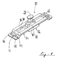
- the locking device 18 shown in FIG. 1 essentially consists of three components: a relative to the bottom of the frame groove 24 upper guide plate 30, a in / "under” the guide plate slidably guided locking slide 32 and one advantageous (but purely optional) lower retaining tab 34.
- the closing device 18 can e.g. be designed as a zinc / die-cast version (especially the locking slide 32) and / or at least partially also consist of reinforced plastic.
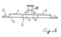
- the guide plate 30 essentially has a strip shape in a plan view and consists e.g. from a steel sheet, which in a hat rail-like in the side view Contour was formed (see also Fig. 2).
- a middle management section 36 with a central slot 38 is at its two opposite ends first bent vertically downwards and then again vertically outwards, so that the end portions of the guide portion are substantially stepped Connect mounting straps 40.
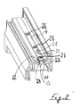
- the mounting tabs 40 are each with two outer recesses 44 for receiving locking cams 42 of the retaining tab 34 and bores 46 provided for receiving screws 47 (see Fig. 3) for screwing the locking device 18 in the groove base of the locking bar groove 24 serve.
- the slot 38 of the sturdy steel or aluminum sheet simple and straightforward producible guide plate 30 is used to guide the locking pin 28 of the closing slide 32. With this pairing, the tolerances can advantageously be narrow be interpreted.
- the locking slide 32 has a lower base area 48 which is larger Has width than the slot 38 and for guiding the locking slide 32 below the Guide plate 30 and for stable engagement behind the guide plate 30 is used.
- the base region 48 of the closing slide 32 is opened by the guide plate 30 the groove bottom of the frame groove 24 held.
- the tilting forces are derived by the guide plate 30 directly onto the frame profile 2. This ensures a very high level of stability and thus a high level of security against break-ins achieved with windows and doors, which with the invention Locking device are provided.
- a base area 50 is molded onto the base area 48 of the closing slide 32, which reaches through the elongated hole 38 of the guide plate 30 and from the locking bar 4, which generates the movement of the closing slide 32.
- the locking pin 28 is in turn molded / attached, the protrudes beyond the level of the locking bar 4 and from the level of the profile surface protrudes.
- the locking pin 28 is advantageous in the embodiment shown shaped as a so-called mushroom head; other variants are also conceivable, e.g. B. cylindrical Locking pin with and without rollers. The mushroom head can be used for this closing edges to increase the locking security of the construction to reach behind a security striker on the window frame (not shown here).
- the locking slide 32 is by the retaining tab 34 under the guide plate 32 held or secured.
- the function of the retaining tab 4 can also through other holding mechanisms - e.g. B. by undercuts on the locking slide - fulfilled become.
- the holding tab 34 is provided with locking cams 42 (or locking hooks) which in the Engage recesses 44 of the guide plate 30.
- the retaining tab 34 is preferred Made of a plastic, which also gives the sliding properties can be improved on the ground, especially if this construction is built into a metal profile.
- the locking bar lock with the clamping screws 26 is in the area of the screw connection performed with the screw 47 (see FIG. 3) for the guide plate 30, so that the guide plate 30 through the openings of the locking bar for the clamping screws 26 can be solved for disassembly, so that both the Locking device 18 and the locking bars in the groove direction from the locking bar / frame groove 24 can be pushed out.
- the locking device 18 and the locking bars 4, 6, 8 are from above inserted into the frame groove 24. Disassembly in this direction, however, is without destruction of the bolt undercuts is not possible.
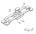
- FIG. 4 shows a variant of the locking device 18 without the optional lower retaining tab 34 shown.
- the closing slide 32 is in a simple manner at the top by cams 52, which each protrude laterally over the edge of the elongated hole 38, on the sides of the base area 50 and down through the base area 48 held on the guide plate 30.
- the locking slide is installed via the recesses 54 in the side areas at one end of the elongated hole 38, which are adapted to the geometry of the cams 52 so that it is possible to At this point, insert the slide carriage into the guide plate 30 from below and then screwed into the frame groove 24. As a result, the retaining tab 34 can be saved become.
- the retaining tab is saved in an even simpler way.
- the locking slide 32 is on the sides of the base area 50 provided smaller projections 56, which form a slight undercut.
- the locking slide 32 is in this variant of the invention when installed in the Guide plate 3 with so much pressure inserted into the slot 38 that the projections 56 snap onto the surface of the guide section 36. It is not because of this once again necessary, the recesses at the end of the elongated hole 38 in the manner of FIG. 4 to provide.
- Fig. 6 finally shows a variant of the invention, in which a locking of the Closing slide 32 by means of shear pins 58 formed / attached to the retaining tab 34 takes place, which in the assembly of the locking device 18 in corresponding bores / openings 60 engage in the bottom of the base area 48.
- the locking slide 32 is positioned in its assembly in the frame groove 24 so that the holes the locking bars 4, 6, 8 always with the locking pins during their subsequent assembly 28 are aligned without the locking slide 32 being carefully positioned first and / or would have to be locked.
- pins 58 are sheared off.
- the closing slide 32 can then move freely.
- the shear pins 56 can also be on the guide plate 34 for the closing slide 32 (not shown here). Is conceivable finally, positioning the shear pins 56 laterally to the locking slide 32 and shear off these side shear pins 56 upon the first actuation of the locking bar 2, 4, 6 with the locking slide 32 (also not shown here).
Abstract
Description
Die Erfindung betrifft eine Schließeinrichtung für einen Beschlag ― insbesondere einen Riegelstangenbeschlag - zur Verriegelung eines beweglichen Rahmenteils eines Fensters oder einer Tür an einem festen Rahmenteil, wobei die Schließeinrichtung in dem beweglichen Rahmenteil angeordnet ist und einen Verriegelungszapfen aufweist, der mit einer Riegel- oder Treibstange gekoppelt und mit dieser am beweglichen Rahmenteil in einer Rahmennut verschiebbar geführt ist.The invention relates to a locking device for a fitting - in particular one Locking bar fitting - for locking a movable frame part of a window or a door on a fixed frame part, the locking device in the movable frame part is arranged and has a locking pin which coupled with a locking or drive rod and with this on the movable frame part is slidably guided in a frame groove.
Aus dem Stand der Technik der DE 35 45 861 sind ein Stahlbeschlag und ein Kunststoff-Riegelstangenbeschlag bekannt.A steel fitting and a plastic locking bar fitting are from the prior art of DE 35 45 861 known.
Der Stahlbeschlag weist eine Stulpschiene auf, die auf eine Rahmenprofilnut geschraubt wird und unter der eine Treibstange längs verfahrbar angeordnet ist. Diese verfahrbare Treibstange wird unter der Stulpschiene geführt und ist unter anderem mit Schließteilen versehen, die durch Langlöcher aus der Oberflächenebene der Stulpschiene herausragen und zum Verriegeln des Flügelrahmens im Blendrahmen bzw. in entsprechenden Blendrahmen Bauteilen dienen.The steel fitting has a faceplate that is screwed onto a frame profile groove is and under which a drive rod is arranged to be longitudinally movable. This Movable drive rod is guided under the faceplate and is among other things with Provide locking parts through elongated holes from the surface level of the faceplate protrude and to lock the casement in the frame or in corresponding frame components are used.
Der gattungsgemäße Riegelstangenbeschlag der DE 35 45 861 liegt formschlüssig in einer speziell ausgebildeten Rahmenprofilnut des beweglichen Rahmenteils, wobei bei dieser Riegelstange die Verriegelungszapfen, ähnlich zur Treibstange des Stahlbeschlages, direkt mit der Riegelstange gekoppelt sind, um ihrerseits den beweglichen Flügel am festen Flügel zu verriegeln.The generic locking bar fitting of DE 35 45 861 lies in a form-fitting manner a specially designed frame profile groove of the movable frame part, with this locking bar the locking pins, similar to the drive rod of the steel fitting, are directly coupled to the locking bar in order to in turn move Lock wing on fixed wing.
Die Kräfte, die auf die Schließelemente einwirken, werden bei beiden Beschlägen über die Treib- bzw. Riegelstange auf die Rahmenprofile übertragen.The forces acting on the locking elements are over with both fittings transfer the drive or locking bar to the frame profiles.
Ausgehend von dem bekannten Riegelstangenbeschlag, der sich an sich bewährt hat, setzt die Erfindung beim Erkennen des Problems an, eine zur Riegelstange separate Schließeinrichtung zu schaffen, die derart ausgestaltet ist, daß die Montage des Beschlages bei erhöhter Funktionalität vereinfacht wird.Based on the well-known locking bar fitting, which has proven itself, the invention sets in recognizing the problem, one separate from the locking bar To create a locking device which is designed such that the assembly of the fitting is simplified with increased functionality.
Die Erfindung nimmt sich dieses Problems an und löst es durch den Gegenstand des Anspruches 1, wonach die Schließeinrichtung separat direkt von außen in die Rahmennut des beweglichen Rahmenteils oder eines einzelnen Rahmenholmes (falls die Holme noch nicht zum Rahmenteil zusammengesetzt wurden) für das bewegliche Rahmenteil einsetzbar ist.The invention addresses this problem and solves it by the subject of Claim 1, according to which the locking device separately directly from the outside into the frame groove of the movable frame part or a single frame spar (if the Spars have not yet been assembled into the frame part) for the movable Frame part can be used.
Durch die erfindungsgemäße Ausgestaltung der Schließeinrichtung ist es möglich, die Schließeinrichtung direkt von außen in der Rahmennut des Rahmenteils zu verankern, beispielsweise zu verschrauben. Nachteilig bei dem gattungsgemäßen Stahlbeschlag wie auch bei dem Riegelstangenbeschlag ist nämlich nach einer Erkenntnis der Erfindung, daß beide Beschläge nicht komplett von außen eingesetzt werden können, so daß eine automatische Montage hierdurch behindert wird. Weiterhin ist bei beiden Beschlägen nachteilig, daß bei einer Belastung der Verriegelungszapfen diese aufgrund der erforderlichen großen Toleranz der Treib- bzw. Riegelstange in ihren Führungen leicht verdreht werden können, so daß ein Hintergreifen der Verriegelungszapfen an einem entsprechenden Riegelstück des Blendrahmens keine großen Kräfte aufnehmen kann.The inventive design of the locking device makes it possible to To anchor the locking device directly from the outside in the frame groove of the frame part, for example to screw. A disadvantage of the generic steel fitting as with the locking bar fitting, according to one finding of the invention, that both fittings can not be used completely from the outside, so that an automatic assembly is hindered by this. Furthermore, with both fittings disadvantageous that due to a load on the locking pin the required large tolerance of the drive or locking bar in their guides can be easily rotated so that the locking pin engages behind do not absorb large forces with a corresponding locking piece of the frame can.
Dagegen schafft die Erfindung eine Schließeinrichtung, die ― besonders vorteilhaft senkrecht von oben - in die Riegelstangennut eingeführt werden kann und somit für eine vollautomatische Montage geeignet ist. Die durch die Riegelstange verfahrbare Schließeinrichtung verfügt über eine einwandfreie Führung, so daß die Schließeinrichtung nur geringen Toleranzen ausgesetzt ist, was unerwünschte Kippbewegungen verhindert und eine Verriegelung sicherstellt, die auch größeren Belastungen problemlos standhält.In contrast, the invention provides a locking device that - particularly advantageous vertically from above - can be inserted into the locking bar groove and thus for fully automatic assembly is suitable. The one that can be moved by the locking bar Locking device has a perfect guide, so that the locking device is exposed to only slight tolerances, causing undesirable tilting movements prevented and a lock ensures that even larger loads easily withstands.
Vorzugsweise ist die Schließeinrichtung als separate Baueinheit unabhängig von der Riegel- oder Treibstange in die Rahmennut einsetzbar (und vorzugsweise dort verrastbar) und/oder mit einer Bohrung zur Aufnahme des Verriegelungszapfens der Schließeinrichtung versehen. Durch diese Maßnahmen wird die Montage des Fensters oder der Tür weiter vereinfacht.As a separate structural unit, the locking device is preferably independent of the Latch or drive rod can be inserted into the frame groove (and preferably locked there) and / or with a bore for receiving the locking pin Provide locking device. Through these measures, the assembly of the window or the door further simplified.
Besonders bevorzugt umfaßt die Schließeinrichtung ein in der Rahmennut des Rahmenteils arretierbares Führungselement ― vorzugsweise als Führungsblech ausgebildet - sowie einen am oder im Führungselement verschiebbar geführten Schließschlitten mit dem Verriegelungszapfen. Ein besonderer Vorteil dieser auch unabhängig zu betrachtenden Variante der Erfindung ist darin zu sehen, daß die Schließeinrichtung oder Schließeinheit unabhängig von der Riegelstange in der Riegelstangennut positionierbar und arretierbar ist. Dabei dient die Riegelstange lediglich als Bewegungselement. Sie muß keine seitlichen Kräfte quer zur Profilerstreckung aufnehmen, welche über die Schließeinrichtung ohne weiteres abgeleitet werden.The locking device particularly preferably comprises a in the frame groove of the frame part lockable guide element - preferably designed as a guide plate - And a sliding carriage guided on or in the guide element with the locking pin. A particular advantage of these can also be viewed independently Variant of the invention can be seen in the fact that the locking device or The locking unit can be positioned in the locking bar groove independently of the locking bar and can be locked. The locking bar serves only as a moving element. she does not have to absorb lateral forces transverse to the profile extension, which over the Locking device can be derived easily.
Hervorzuheben ist noch, daß sich die erfindungsgemäßen Schließeinrichtungen für Rahmen aus verschiedensten Materialien wie Aluminium, Stahl, Holz oder insbesondere auch Kunststoff eignet.It should also be emphasized that the locking devices according to the invention for Frame made of various materials such as aluminum, steel, wood or in particular plastic is also suitable.
Weitere vorteilhafte Ausgestaltungen der Erfindung sind den übrigen Unteransprüchen zu entnehmen.Further advantageous embodiments of the invention are the other subclaims refer to.
Nachfolgend wird die Erfindung unter Bezug auf die Zeichnung anhand von Ausführungsbeispielen
näher beschrieben. Es zeigt:
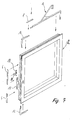
Der in Fig. 7 dargestellte Flügelrahmen 2, dessen Holme aus Metall, Holz oder Kunststoff
gefertigt sein können, weist einen Riegelstangenbeschlag auf, bei dem Riegelstangen
4, 6, 8 mit unterschiedlichen Längen zum Einsatz kommen.The casement 2 shown in Fig. 7, the spars made of metal, wood or plastic
can be manufactured, has a locking bar fitting, in the
Der Riegelstangenbeschlag der Fig. 7 ist ferner mit einem Kammergetriebe 10, mit
Eckumlenkungen 12, 14, einer Ausstellschere 16 sowie einer Schließeinrichtung 18
versehen.7 is also with a
Aus der Darstellung der Fig. 7 und den aufgezeigten Montagepfeilen ist ersichtlich, daß sämtliche Bauteile des Riegelstangenbeschlags von außen auf den zuvor fertiggestellten Flügelrahmen 2 montiert werden.From the illustration in FIG. 7 and the assembly arrows shown, it can be seen that all components of the locking bar fitting from the outside to the previously completed Sash frame 2 can be mounted.
Wie in Fig. 3 zu erkennen, weisen die Riegelstangen 4, 6, 8 nutenförmige Aufnahmen
20 für die Randleisten 22 einer Rahmennut 24 auf Die nutförmige Aufnahmen 20
werden hier von federelastischen Stegen (hier nicht zu erkennen) begrenzt, welche
beim Einsetzen der Riegelstangen in die Rahmennut elastisch verformt werden, bis
Hinterschnittflächen (hier ebenfalls nicht zu erkennen) die Randleisten 22 hintergreifen.
Da somit die Riegelstangen 4, 6, 8 auf den fertigen Flügelrahmen von außen
montiert werden können und auch die übrigen Bauteile des Riegelstangenbeschlages
von außen auf den Flügelrahmen montierbar sind, kann eine vollautomatischen Montage
der Bauteile des Riegelstangenbeschlages vorgenommen werden. Hierbei erfolgt
vorzugsweise die Kopplung der jeweiligen auf ihre Sollänge zugeschnittenen Riegelstange
4, 6, 8 ― die z.B. aus einem flexiblen Kunststoff bestehen kann - mit den zugeordneten
Beschlagteilen. In ihrer Endlage in der Rahmennut 24 können die Riegelstangen
4, 6, 8 mit Klemmschrauben 26 fixiert werden, welche beispielsweise untere
Stege (hier nicht zu erkennen) an den nutförmigen Aufnahmen 20 an die Randleisten
22 der Rahmennut 24 pressen (hier ebenfalls nicht dargestellt).As can be seen in Fig. 3, the
Die Schließeinrichtung 18 weist eine Breite auf, die nicht größer ist als die Breite der
Öffnung der Riegelstangennut 24, und kann ― wie in Fig. 7 angedeutet ― ebenfalls
![]()
![]()
Die in Fig. 1 dargestellte Schließeinrichtung 18 besteht im wesentlichen aus drei Bauteilen:
einem relativ zum Boden der Rahmennut 24 oberen Führungsblech 30, einem
im/"unter" dem Führungsblech verschiebbar geführten Schließschlitten 32 und einer
vorteilhaften (aber rein optionalen) unteren Haltelasche 34. Die Schließeinrichtung 18
kann z.B. als Zink-/Druckgußausführung ausgebildet sein (insbesondere der Schließschlitten
32) und/oder zumindest teilweise auch aus verstärktem Kunststoff bestehen.The
Das Führungsblech 30 weist in einer Draufsicht im wesentlichen eine Streifenform auf
und besteht z.B. aus einem Stahlblech, welches in eine in der Seitenansicht hutschienenartige
Kontur geformt wurde (siehe auch Fig. 2). Ein mittlerer Führungsabschnitt
36 mit einem zentralen Langloch 38 wird an seinen beiden gegenüberliegenden Enden
zunächst jeweils senkrecht nach unten und dann nochmals senkrecht nach außen abgebogen,
so daß sich an die Endabschnitte des Führungsabschnittes im wesentlichen abgestufte
Befestigungslaschen 40 anschließen. Die Befestigungslaschen 40 sind jeweils
mit zwei äußeren Ausnehmungen 44 zur Aufnahme von Rastnocken 42 der Haltelasche
34 und Bohrungen 46 versehen, die zur Aufnahme von Schrauben 47 (siehe Fig.
3) zum Verschrauben der Schließeinrichtung 18 im Nutgrund der Riegelstangennut 24
dienen.The
Das Langloch 38 des aus stabilem Stahl- oder Aluminiumblech einfach und unkompliziert
fertigbaren Führungsbleches 30 dient zur Führung des Verriegelungszapfens 28
des Schließschlittens 32. Bei dieser Paarung können die Toleranzen vorteilhaft eng
ausgelegt werden.The
Der Schließschlitten 32 weist einen unteren Basisbereich 48 auf, der eine größere
Breite als das Langloch 38 hat und zur Führung des Schließschlittens 32 unterhalb des
Führungsbleches 30 sowie zum stabilen Hintergreifen des Führungsbleches 30 dient.
Der Basisbereich 48 des Schließschlittens 32 wird durch das Führungsblech 30 auf
dem Nutgrund der Rahmennut 24 gehalten. Bei Belastung des Schließschlittens 32
werden die Kippkräfte durch das Führungsblech 30 direkt auf das Rahmenprofil 2 abgeleitet.
Hierdurch wird eine sehr hohe Standfestigkeit und damit auch eine hohe Einbruchsicherheit
bei Fenstern und Türen erreicht, welche mit der erfindungsgemäßen
Schließeinrichtung versehen sind.The
Auf den Basisbereich 48 des Schließschlittens 32 ist ein Sockelbereich 50 aufgeformt,
der durch das Langloch 38 des Führungsbleches 30 greift und von der Riegelstange 4,
welche die Bewegung des Schließschlittens 32 erzeugt, umgriffen wird. Auf den Sockelbereich
50 ist wiederum der Verriegelungszapfen 28 aufgeformt/aufgesetzt, der
über die Ebene der Riegelstange 4 vorsteht und aus der Ebene der Profiloberfläche
heraus ragt. Der Verriegelungszapfen 28 ist in der dargestellten Ausführung vorteilhaft
als sogenannter Pilzkopf ausgeformt; andere Varianten sind ebenso denkbar, z. B. zylindrische
Verriegelungszapfen mit und ohne Rollen. Der Pilzkopf kann dazu genutzt
werden, zur Erhöhung der Verriegelungssicherheit der Konstruktion Schließkanten
eines Sicherheitsschließstücks am Fensterrahmen zu hintergreifen (hier nicht dargestellt).A
Zur besseren Montage bzw. damit der Schließschlitten mit dem Führungsblech eine
Einheit bildet, wird der Schließschlitten 32 durch die Haltelasche 34 unter dem Führungsblech
32 gehalten bzw. gesichert. Die Funktion der Haltelasche 4 kann auch
durch andere Haltemechanismen - z. B. durch Hinterschnitte am Schließschlitten - erfüllt
werden.For better assembly and thus the locking slide with the guide plate
Forms unit, the
Die Haltelasche 34 ist mit Rastnocken 42 versehen (bzw. Rasthaken) welche in die
Ausnehmungen 44 des Führungsblechs 30 eingreifen. Die Haltelasche 34 wird vorzugsweise
aus einem Kunststoff hergestellt, wodurch auch noch die Gleiteigenschaften
auf dem Untergrund verbessert werden können, insbesondere wenn diese Konstruktion
in ein Metallprofil eingebaut wird.The
An der Schließeinrichtung treten einerseits Verriegelungskräfte auf, die in der Richtung
der Längsachse, d.h. beim Verschließen oder Öffnen in Bewegungsrichtung bzw.
in der Erstreckungsrichtung des Langlochs 38 auftreten. Andererseits wirken auf den
Flügel - z. B. durch Windlasten oder aber auch Einbruchversuche ― Kräfte quer zur
Erstreckung des Langlochs 38. Es hat sich bei Tests ― insbesondere der Simulation von
Einbruchsversuchen - gezeigt, daß die Verschraubung des Führungsbleches in der
Rahmenprofilnut sehr hohe Widerstandswerte erreicht. In diesem Zusammenhang ist
noch anzumerken, daß die Rahmenprofile aus unterschiedlichen Werkstoffen bestehen
können. Kunststoffprofile weisen in der Regel Stahlarmierungen auf, welche aufgrund
ihrer Stabilität an sich zur Aufnahme der Verschraubung am besten geeignet erscheinen.
Versuche haben aber ergeben, daß es nicht einmal unbedingt erforderlich ist, die
Verschraubung in die Stahlarmierung des Rahmenprofils zu setzen. Die Verschraubungen
können vielmehr auch direkt in den Kunststoff geschraubt werden, ohne daß
die Stabilität der Konstruktion zu sehr nachläßt.On the one hand, locking forces occur in the locking device in the direction
the longitudinal axis, i.e. when closing or opening in the direction of movement or
occur in the direction of extension of the
Die Riegelstangenarretierung mit den Klemmschrauben 26 wird im Bereich der Verschraubung
mit der Schraube 47 (siehe Fig. 3) für das Führungsblech 30 durchgeführt,
damit das Führungsblech 30 durch die Öffnungen der Riegelstange für die Klemmschrauben
26 hindurch zur Demontage gelöst werden kann, so daß sowohl die
Schließeinrichtung 18 als auch die Riegelstangen in Nutrichtung aus der Riegelstangen-/Rahmennut
24 herausgeschoben werden können.The locking bar lock with the clamping screws 26 is in the area of the screw connection
performed with the screw 47 (see FIG. 3) for the
Zur Montage werden die Schließeinrichtung 18 und die Riegelstangen 4, 6, 8 von oben
in die Rahmennut 24 eingesetzt. Eine Demontage in dieser Richtung ist dagegen ohne
eine Zerstörung der Riegelstangenhinterschnitte nicht möglich.For assembly, the locking
In Figur 4 ist eine Variante der Schließeinrichtung 18 ohne die optionale untere Haltelasche
34 dargestellt. Der Schließschlitten 32 wird hierbei in einfacher Weise nach
oben hin durch Nocken 52, die jeweils seitlich über den Rand des Langloches 38 vorstehen,
an den Seiten des Sockelbereiches 50 und nach unten hin durch den Basisbereich
48 am Führungsblech 30 gehalten. Die Montage des Schließschlittens erfolgt
über die Ausnehmungen 54 in den Seitenbereichen an einem Ende des Langloches 38,
welche der Geometrie der Nocken 52 derart angepaßt sind, so daß es möglich ist, den
Schließschlitten an dieser Stelle von unten in das Führungsblech 30 einzuschieben und
dann in der Rahmennut 24 zu verschrauben. Hierdurch kann die Haltelasche 34 eingespart
werden. FIG. 4 shows a variant of the
In Figur 5 wird die Haltelasche auf noch einfachere Weise eingespart. Bei dieser Ausführungsvariante
ist der Schließschlitten 32 an den Seiten des Sockelbereiches 50 mit
kleineren Vorsprüngen 56 versehen, welche einen leichten Hinterschnitt ausbilden.
Der Schließschlitten 32 wird bei dieser Variante der Erfindung bei der Montage in das
Führungsblech 3 mit soviel Druck in das Langloch 38 eingeführt, daß die Vorsprünge
56 auf der Oberfläche des Führungsabschnittes 36 einrasten. Hierdurch ist es nicht
einmal mehr nötig, die Ausnehmungen am Ende des Langlochs 38 nach Art der Fig. 4
vorzusehen.In Figure 5, the retaining tab is saved in an even simpler way. In this variant
the locking
Fig. 6 zeigt schließlich eine Variante der Erfindung, bei welcher eine Arretierung des
Schließschlittens 32 durch an die Haltelasche 34 angeformte/angesetzte Scherstifte 58
erfolgt, welche bei der Montage der Schließeinrichtung 18 in korrespondierende Bohrungen/Öffnungen
60 im Boden des Basisbereiches 48 eingreifen.Fig. 6 finally shows a variant of the invention, in which a locking of the
Damit wird auf besonders unkomplizierte Weise gewährleistet, daß der Schließschlitten
32 bei seiner Montage in der Rahmennut 24 so positioniert ist, daß die Bohrungen
der Riegelstangen 4, 6, 8 bei ihrer anschließenden Montage stets mit den Verriegelungszapfen
28 fluchten, ohne daß der Schließschlitten 32 erst sorgfältig positioniert
und/oder arretiert werden müßte. Nach der ersten Betätigung der Riegelstange zusammen
mit dem Schließschlitten 32 im fest in der Rahmennut 24 verschraubten Führungsblech
30 werden die Stifte 58 abgeschert. Der Schließschlitten 32 kann sich dann
frei bewegen. Alternativ/Optional können die Scherstifte 56 auch am Führungsblech
34 für den Schließschlitten 32 ausgebildet sein (hier nicht dargestellt). Denkbar ist
schließlich auch eine Positionierung der Scherstifte 56 seitlich zum Schließschlitten 32
und ein Abscheren dieser seitlichen Scherstifte 56 bei der ersten Betätigung der Riegelstange
2, 4, 6 mit dem Schließschlitten 32 (hier ebenfalls nicht dargestellt). This ensures in a particularly uncomplicated manner that the locking
- FlügelrahmenCasement
- 22nd
- RiegelstangenLocking bars
- 4, 6, 84, 6, 8
- KammergetriebeChamber gear
- 1010th
- EckumlenkungCorner deflection
- 12, 1412, 14
- AusstellschereFolding scissors
- 1616
- SchließeinrichtungLocking device
- 1818th
- nutförmige Aufnahmengroove-shaped recordings
- 2020th
- RandleistenSidebars
- 2222
- RahmennutFrame groove
- 2424th
- KlemmschraubenClamping screws
- 2626
- VerriegelungszapfenLocking pin
- 2828
- Bohrungdrilling
- 2929
- FührungsblechGuide plate
- 3030th
- SchließschlittenClosing slide
- 3232
- HaltelascheRetaining tab
- 3434
- FührungsabschnittGuide section
- 3636
- LanglochLong hole
- 3838
- BefestigungslaschenMounting tabs
- 4040
- AusnehmungenRecesses
- 4141
- RastnockenLocking cams
- 4242
- AusnehmungenRecesses
- 4444
- BohrungenHoles
- 4646
- SchraubenScrews
- 4747
- BasisbereichBase area
- 4848
- SockelbereichPlinth area
- 5050
- Nockencam
- 5252
- AusnehmungenRecesses
- 5454
- VorsprüngeLedges
- 5656
- ScherstifteShear pins
- 5858
- BohrungenHoles
- 6060
Claims (21)
Applications Claiming Priority (2)
| Application Number | Priority Date | Filing Date | Title |
|---|---|---|---|
| DE1999148862 DE19948862A1 (en) | 1999-10-08 | 1999-10-08 | Locking device for a fitting for locking a movable frame part of a window or a door |
| DE19948862 | 1999-10-08 |
Publications (2)
| Publication Number | Publication Date |
|---|---|
| EP1091065A2 true EP1091065A2 (en) | 2001-04-11 |
| EP1091065A3 EP1091065A3 (en) | 2003-04-09 |
Family
ID=7925187
Family Applications (1)
| Application Number | Title | Priority Date | Filing Date |
|---|---|---|---|
| EP00121749A Withdrawn EP1091065A3 (en) | 1999-10-08 | 2000-10-05 | Locking element for a lock-fitting of a movable door- or window-wing |
Country Status (2)
| Country | Link |
|---|---|
| EP (1) | EP1091065A3 (en) |
| DE (1) | DE19948862A1 (en) |
Cited By (3)
| Publication number | Priority date | Publication date | Assignee | Title |
|---|---|---|---|---|
| DE10136316A1 (en) * | 2001-07-26 | 2003-02-13 | Winkhaus Fa August | Strike plate for a connecting rod fitting |
| EP2151537A3 (en) * | 2008-08-07 | 2011-07-27 | Aug. Winkhaus GmbH & Co. KG | Fitting part for a connecting rod fitting |
| DE102013100308A1 (en) * | 2013-01-11 | 2014-07-17 | SCHÜCO International KG | Bar fitting for a window or a door |
Families Citing this family (2)
| Publication number | Priority date | Publication date | Assignee | Title |
|---|---|---|---|---|
| ITBO20010080A1 (en) † | 2001-02-14 | 2002-08-14 | Gsg Int Spa | METHOD OF REALIZATION OF ACCESSORY ELEMENTS FOR WINDOWS AND EQUIPMENT IMPLEMENTING SUCH METHOD |
| DE102016225133A1 (en) * | 2016-12-15 | 2018-06-21 | Roto Frank Ag | Fitting with a through hole having a face plate |
Citations (1)
| Publication number | Priority date | Publication date | Assignee | Title |
|---|---|---|---|---|
| DE3545861A1 (en) | 1985-12-23 | 1987-07-02 | Schuermann & Co Heinz | WINDOW OR DOOR WITH A LOCKING BAR FITTING OPERATED BY A HAND LEVER |
Family Cites Families (4)
| Publication number | Priority date | Publication date | Assignee | Title |
|---|---|---|---|---|
| DE7603368U1 (en) * | 1976-02-06 | 1976-06-03 | Wilh. Frank Gmbh, 7022 Leinfelden | FITTING PART FOR A WINDOW, A DOOR OR DGL. |
| DE3719011A1 (en) * | 1987-06-06 | 1988-12-22 | Bilstein August Gmbh Co Kg | LOCKING FITTING FOR WINDOWS, DOORS OD. DGL. |
| FR2722527B1 (en) * | 1994-07-13 | 1996-12-27 | Alcan France Sa | LOCKING DEVICE FOR HITCH CHASSIS |
| DE19909400A1 (en) * | 1999-03-04 | 2000-09-07 | Siegenia Frank Kg | Window or door, fitting for a window or door, and method for manufacturing a window or door |
-
1999
- 1999-10-08 DE DE1999148862 patent/DE19948862A1/en not_active Withdrawn
-
2000
- 2000-10-05 EP EP00121749A patent/EP1091065A3/en not_active Withdrawn
Patent Citations (1)
| Publication number | Priority date | Publication date | Assignee | Title |
|---|---|---|---|---|
| DE3545861A1 (en) | 1985-12-23 | 1987-07-02 | Schuermann & Co Heinz | WINDOW OR DOOR WITH A LOCKING BAR FITTING OPERATED BY A HAND LEVER |
Cited By (3)
| Publication number | Priority date | Publication date | Assignee | Title |
|---|---|---|---|---|
| DE10136316A1 (en) * | 2001-07-26 | 2003-02-13 | Winkhaus Fa August | Strike plate for a connecting rod fitting |
| EP2151537A3 (en) * | 2008-08-07 | 2011-07-27 | Aug. Winkhaus GmbH & Co. KG | Fitting part for a connecting rod fitting |
| DE102013100308A1 (en) * | 2013-01-11 | 2014-07-17 | SCHÜCO International KG | Bar fitting for a window or a door |
Also Published As
| Publication number | Publication date |
|---|---|
| DE19948862A1 (en) | 2001-04-12 |
| EP1091065A3 (en) | 2003-04-09 |
Similar Documents
| Publication | Publication Date | Title |
|---|---|---|
| EP1437471B1 (en) | Fitting for a lifting and sliding door or a lifting and sliding window | |
| CH624729A5 (en) | ||
| DE202022100517U1 (en) | Profile arrangement of a window or a door with a casement profile, in particular a sliding casement profile | |
| EP2252751B1 (en) | Espagnolette fitting for window or door | |
| EP3266969B1 (en) | Corner deflection of a fitting for a wing of a window or a door | |
| EP1091065A2 (en) | Locking element for a lock-fitting of a movable door- or window-wing | |
| EP0844348B1 (en) | Hinge for doors or windows | |
| DE3334298C3 (en) | Lock for windows, doors or the like | |
| DE19740603C2 (en) | Forend rail fastening | |
| EP1264954B1 (en) | Locking device | |
| DE19909400A1 (en) | Window or door, fitting for a window or door, and method for manufacturing a window or door | |
| EP0493689A1 (en) | Espagnolette for windows, doors or the like | |
| EP3443185B1 (en) | Fitting for two at least liftable and slidable sashes of windows or doors | |
| EP2122092B1 (en) | Fitting | |
| DE102015206908A1 (en) | Window, door or the like with a fitting | |
| DE19734647B4 (en) | Fitting part on a wing or a fixed frame of a window, a door od. Like. | |
| EP3783176B1 (en) | Drive rod fitting, door or window closure and door or window assembly | |
| DE1964842A1 (en) | Fitting for windows, doors and the like. | |
| EP1031692B1 (en) | Closure plate for closures on windows and/or doors of buildings | |
| DE2411114C3 (en) | Fitting for a wing of windows, doors or the like consisting of profiled frame parts. | |
| EP1270856B1 (en) | Fitting for locking of windows or doors | |
| WO2017001226A1 (en) | Drop-down seal | |
| DE19912839A1 (en) | Concealed central locking system for sliding parallel window or door sashes | |
| DE60300577T2 (en) | Bolt fitting for sliding sash | |
| DE102015206905A1 (en) | Geared fitting and window, door or the like with a geared fitting |
Legal Events
| Date | Code | Title | Description |
|---|---|---|---|
| PUAI | Public reference made under article 153(3) epc to a published international application that has entered the european phase |
Free format text: ORIGINAL CODE: 0009012 |
|
| AK | Designated contracting states |
Kind code of ref document: A2 Designated state(s): AT BE CH CY DE DK ES FI FR GB GR IE IT LI LU MC NL PT SE |
|
| AX | Request for extension of the european patent |
Free format text: AL;LT PAYMENT 20001009;LV PAYMENT 20001009;MK;RO;SI |
|
| PUAL | Search report despatched |
Free format text: ORIGINAL CODE: 0009013 |
|
| AK | Designated contracting states |
Kind code of ref document: A3 Designated state(s): AT BE CH CY DE DK ES FI FR GB GR IE IT LI LU MC NL PT SE Designated state(s): AT BE CH CY DE DK ES FI FR GB GR IE IT LI LU MC NL PT SE |
|
| AX | Request for extension of the european patent |
Extension state: AL LT LV MK RO SI |
|
| RIC1 | Information provided on ipc code assigned before grant |
Ipc: 7E 05C 9/20 B Ipc: 7E 05C 9/22 B Ipc: 7E 05C 9/18 A |
|
| 17P | Request for examination filed |
Effective date: 20030925 |
|
| AKX | Designation fees paid |
Designated state(s): AT BE CH CY DE DK ES FI FR GB GR IE IT LI LU MC NL PT SE |
|
| AXX | Extension fees paid |
Extension state: LV Payment date: 20001009 Extension state: LT Payment date: 20001009 |
|
| 17Q | First examination report despatched |
Effective date: 20031219 |
|
| GRAP | Despatch of communication of intention to grant a patent |
Free format text: ORIGINAL CODE: EPIDOSNIGR1 |
|
| STAA | Information on the status of an ep patent application or granted ep patent |
Free format text: STATUS: THE APPLICATION IS DEEMED TO BE WITHDRAWN |
|
| 18D | Application deemed to be withdrawn |
Effective date: 20110503 |