EP3118401A1 - Lock bolt for the edge of a wing - Google Patents
Lock bolt for the edge of a wing Download PDFInfo
- Publication number
- EP3118401A1 EP3118401A1 EP16178541.5A EP16178541A EP3118401A1 EP 3118401 A1 EP3118401 A1 EP 3118401A1 EP 16178541 A EP16178541 A EP 16178541A EP 3118401 A1 EP3118401 A1 EP 3118401A1
- Authority
- EP
- European Patent Office
- Prior art keywords
- lever
- lock body
- pinion
- locking element
- forend
- Prior art date
- Legal status (The legal status is an assumption and is not a legal conclusion. Google has not performed a legal analysis and makes no representation as to the accuracy of the status listed.)
- Withdrawn
Links
Images


Classifications
-
- E—FIXED CONSTRUCTIONS
- E05—LOCKS; KEYS; WINDOW OR DOOR FITTINGS; SAFES
- E05C—BOLTS OR FASTENING DEVICES FOR WINGS, SPECIALLY FOR DOORS OR WINDOWS
- E05C9/00—Arrangements of simultaneously actuated bolts or other securing devices at well-separated positions on the same wing
- E05C9/04—Arrangements of simultaneously actuated bolts or other securing devices at well-separated positions on the same wing with two sliding bars moved in opposite directions when fastening or unfastening
- E05C9/041—Arrangements of simultaneously actuated bolts or other securing devices at well-separated positions on the same wing with two sliding bars moved in opposite directions when fastening or unfastening with rack and pinion mechanism
-
- E—FIXED CONSTRUCTIONS
- E05—LOCKS; KEYS; WINDOW OR DOOR FITTINGS; SAFES
- E05B—LOCKS; ACCESSORIES THEREFOR; HANDCUFFS
- E05B15/00—Other details of locks; Parts for engagement by bolts of fastening devices
- E05B15/0053—Other details of locks; Parts for engagement by bolts of fastening devices means providing a stable, i.e. indexed, position of lock parts
-
- E—FIXED CONSTRUCTIONS
- E05—LOCKS; KEYS; WINDOW OR DOOR FITTINGS; SAFES
- E05C—BOLTS OR FASTENING DEVICES FOR WINGS, SPECIALLY FOR DOORS OR WINDOWS
- E05C7/00—Fastening devices specially adapted for two wings
- E05C7/04—Fastening devices specially adapted for two wings for wings which abut when closed
- E05C7/045—Sliding bolts mounted on or in the edge of a normally closed wing of a double-door or -window
-
- E—FIXED CONSTRUCTIONS
- E05—LOCKS; KEYS; WINDOW OR DOOR FITTINGS; SAFES
- E05B—LOCKS; ACCESSORIES THEREFOR; HANDCUFFS
- E05B15/00—Other details of locks; Parts for engagement by bolts of fastening devices
- E05B15/04—Spring arrangements in locks
- E05B2015/0458—Leaf springs; Non-wound wire springs
-
- E—FIXED CONSTRUCTIONS
- E05—LOCKS; KEYS; WINDOW OR DOOR FITTINGS; SAFES
- E05B—LOCKS; ACCESSORIES THEREFOR; HANDCUFFS
- E05B15/00—Other details of locks; Parts for engagement by bolts of fastening devices
- E05B15/04—Spring arrangements in locks
- E05B2015/0493—Overcenter springs
Definitions
- the present invention relates to a channel latch for mounting in a door or window sash, comprising a cuff for attaching the channel latch to a fold of the door or window sash and operable by pivoting out of a plane of the cuff lever, which at least one by the pivoting the lever is a translational movement exporting, is coupled from a locking position into an unlocked position and back convertible locking element.
- a canister with the aforementioned features is made DE 20 2006 008 969 U1 known.
- Can-hangers are used in particular for fixing fixed leaf double-leaf door or window systems.
- a lever pivotally mounted in the lock housing of the can latch has to be pivoted out of the plane of the cuff.
- Kantriegel the lever is coupled via a coupling device with the locking elements.
- the manufacture of the channel bolt is complicated by the provided between the lever and the coupling means second actuating mechanism.
- the forend forms a wall of the lock body and must be elaborately welded to the other walls of the lock body.
- Object of the present invention is therefore to solve the problems described with reference to the prior art, at least partially, and in particular to provide a can bar, the production of which is simple and easy to do.
- a channel latch with the features mentioned, wherein the lever is rotatably connected to a pinion arranged on its pivot axis, wherein teeth of the pinion engage in recesses on the translationally movable locking element, so that the rotation of the pivotal movement of the lever driven pinion drives the at least one locking element translationally.
- the invention thus provides that the conversion of the pivotal movement of the lever in the translational movement of the at least one locking element via a pinion whose axis of rotation coincides with the pivot axis of the lever and which engages directly in recesses on the locking element. Between the lever and locking element in particular only the pinion is provided, which can be easily arranged in the lock body during manufacture.
- the lever is pivotally mounted so that its pivot axis is aligned parallel to the plane of the forend, so that the lever is swung out of the plane of the forend when actuated.
- a locking rod connected to the locking element is moved over a lower or upper end face of the window or door leaf and can engage in a correspondingly provided recess.
- the unlocked position the locking rod is pulled into the door leaf.
- lock rods can be attached to the locking element so provided for the particular purpose lock rods can be attached.
- the teeth of the pinion are adapted in their cross-section in particular to the recesses in the locking element and vice versa, so that the offset by the lever in rotation pinion translates the locking element by continuous engagement of adjacent teeth in adjacent recesses of the locking element.
- the forend is attached to a front wall of a lock body, wherein in the lock body, the lever is rotatably mounted together with the pinion and the at least one locking element is mounted translationally movable.
- the lock body consists of at least one injection molded part, to which the forend can be attached.
- the forend can, for example, be attached to the front wall of the lock body by means of countersunk blind rivets. The forend is therefore not directly part of the lock body.
- projections or recesses are formed on the lock body itself or on a cover closing the lock body, in or between which the lock element can be moved translationally and in or on which the pinion is rotatably mounted.
- the forend and the lock body are made in one piece. It could also be provided that the forend and the lid are made in one piece. In both cases, the forend would, for example Made by injection molding or casting in one piece with the lock body or the lid.
- a spring element at all times acts on an actuating region of the lever with respect to the pivot axis eccentric region, so that the lever is biased either in the unlocked position or in the locking position and thus prevents unintentional actuation of the locking element.
- the spring element ensures that the lever always returns to its starting position. If, on the other hand, when the levers are moved against the spring force beyond the maximum deflection of the eccentric region in the direction of the spring element, then the spring element urges the lever such that the lever reaches the target position.
- the lock body is designed so that for assembly the pinion can be inserted in a predetermined position in the lock body and the lever is laterally mounted on the pinion, wherein the lever through a gap is pivotable between the front wall of the lock body and a side wall mounted as a lid on the lock body, wherein the gap corresponds to an opening arranged asymmetrically in the forend.
- the pinion can initially be inserted into a circular exception or into a mounting position formed by projections. Subsequently, the lever is inserted into the pinion, wherein the lever in the adjacent to the side wall gap of the front wall of the front wall can be swung out.
- the forend has, in a region corresponding to the gap, an opening, which is thus formed in particular asymmetrically with respect to a central longitudinal axis of the forend. Only after the lever has been inserted into the pinion, the forend can be attached to the front wall of the lock body. It can thus be achieved that the pinion and the lever are first placed without tools in the lock body, wherein the positional fixing is achieved by the lid, which is then screwed, for example, to the lock body and thus forms a side wall of the lock body.
- projections and recesses may be formed on the cover, which fix the lever and / or the pinion in their position in the lock body.
- an axle may be formed on the cover about which the lever is pivoted and about which the pinion rotates.
- the opening corresponding to the gap is formed correspondingly in this component.
- the lock body is designed so that the spring element designed as a leaf spring in the lock body in a predetermined position can be inserted, wherein the leaf spring is fixed by the particular releasably attachable to the lock body lid , The leaf spring is aligned after assembly so that it biases the lever either in the locking position or the unlocked position.
- a cover which can be detachably attached to the lock body holds the elements inserted or inserted in the lock body in their respective position, wherein the cover forms a side wall of the lock body.
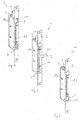
- the channel latch 1 shown in the figures is intended for mounting in a door or window sash, wherein the channel latch 1 is fixed with a forend 2 on the door or window sash.
- the channel latch 1 comprises a lever 3, which is pivotally mounted in a lock body 9. In the region of its pivot axis of the lever 3 is rotatably connected to a teeth 6 having pinion 5.
- the teeth 6 of the pinion 5 engage in recesses 7 in locking elements 4, wherein the locking elements 4 are mounted translationally movable in the lock body 9.
- a leaf spring 10 is further arranged, which acts on an actuating region 11 of the lever 3 opposite eccentric 12.
- the lever 3 can be pivoted laterally past a front wall 8 of the lock body 9.
- the forend 2 has for this purpose a corresponding opening 13 through which the lever 3 passes during pivoting.
- the opening 13 is asymmetrically formed in the forend 2 with respect to its longitudinal axis.
- the locking elements 4 which can be connected to locking rods, in a locking position on the closure body 9 addition.
- the leaf spring 10 acts on the eccentric portion 12 of the lever 3, that the lever 3 can not be operated inadvertently.
- 9 pin-like and plate-like projections are formed on an inner side of the lock body, at or between which the locking elements 4 and the pinion 5 can be inserted.
- the pinion 5 and the locking elements 4 are inserted into the lock body 9.
- the lever 8 is attached to the pinion 5, so that the operating portion 11 of the lever 3 is disposed in a corresponding gap formed between the front wall 8 and the lid 14.
- the leaf spring 10 is attached to provided projections, wherein the leaf spring 10 acts on the eccentric portion 12 of the lever 3.
- the faceplate 2 can be fastened to the front wall 8 of the lock body 9, wherein the actuation region 11 of the lever 3 is arranged in an opening 13 of the forend 2 and the lever 3 can thus no longer be removed from the lock body 9.
- the opening 13 in the forend 2 is formed so that it corresponds to the gap between the front wall 8 and lid 14, through which the lever 3 is pivoted.
- the cover 14 is fastened, for example by means of screws to the lock body 9, whereby the elements arranged in the lock body 9 are additionally held in their respective position.
Abstract
Ein Kantriegel (1) zur Montage in einem Tür- oder Fensterflügel, umfassend einen Stulp (2) zur Befestigung des Kantriegels (1) an einer Falz des Tür- oder Fensterflügels und einen durch Schwenken aus einer Ebene des Stulps heraus betätigbaren Hebel (3), der mit mindestens einem durch das Verschwenken des Hebels (3) eine translatorische Bewegung ausführenden, von einer Verriegelungsstellung in eine Entriegelungsstellung und zurück überführbaren Verriegelungselement (4) gekoppelt ist, welches dadurch gekennzeichnet ist, dass der Hebel (3) mit einem an seiner Schwenkachse angeordneten Ritzel (5) drehfest verbunden ist, wobei Zähne (6) des Ritzels (5) in Ausnehmungen (7) an dem translatorisch bewegbaren Verriegelungselement (4) eingreifen, so dass das von der Schwenkbewegung des Hebels (3) rotatorisch angetriebene Ritzel (5) das mindestens eine Verriegelungselement (4) translatorisch antreibt.

Description
Die vorliegende Erfindung betrifft einen Kantriegel zur Montage in einem Tür- oder Fensterflügel, umfassend einen Stulp zur Befestigung des Kantriegels an einer Falz des Tür- oder Fensterflügels und einen durch Schwenken aus einer Ebene des Stulps heraus betätigbaren Hebel, der mit mindestens einem durch das Verschwenken des Hebels eine translatorische Bewegung ausführenden, von einer Verriegelungsstellung in eine Entriegelungsstellung und zurück überführbaren Verriegelungselement gekoppelt ist.The present invention relates to a channel latch for mounting in a door or window sash, comprising a cuff for attaching the channel latch to a fold of the door or window sash and operable by pivoting out of a plane of the cuff lever, which at least one by the pivoting the lever is a translational movement exporting, is coupled from a locking position into an unlocked position and back convertible locking element.
Ein Kantriegel mit den vorgenannten Merkmalen ist aus
Aufgabe der vorliegenden Erfindung ist es daher, die mit Bezug zum Stand der Technik geschilderten Probleme zumindest teilweise zu lösen und insbesondere einen Kantriegel anzugeben, dessen Herstellung einfach und ohne großen Aufwand möglich ist.Object of the present invention is therefore to solve the problems described with reference to the prior art, at least partially, and in particular to provide a can bar, the production of which is simple and easy to do.
Gelöst wird diese Aufgabe durch einen Kantriegel mit den Merkmalen des unabhängigen Anspruchs. Vorteilhafte Weiterbildungen des Kantriegels sind in den abhängigen Ansprüchen und in der Beschreibung angegeben, wobei Merkmale der vorteilhaften Weiterbildungen in technologisch sinnvoller Weise beliebig miteinander kombinierbar sind.This object is achieved by a canister with the features of the independent claim. Advantageous developments of the can crucible are specified in the dependent claims and in the description, wherein features of advantageous developments in a technologically meaningful manner are combined with each other.
Gelöst wird die Aufgabe insbesondere durch einen Kantriegel mit den eingangs genannten Merkmalen, wobei der Hebel mit einem an seiner Schwenkachse angeordneten Ritzel drehfest verbunden ist, wobei Zähne des Ritzels in Ausnehmungen an dem translatorisch bewegbaren Verriegelungselement eingreifen, so dass das von der Schwenkbewegung des Hebels rotatorisch angetriebene Ritzel das mindestens eine Verriegelungselement translatorisch antreibt.The problem is solved in particular by a channel latch with the features mentioned, wherein the lever is rotatably connected to a pinion arranged on its pivot axis, wherein teeth of the pinion engage in recesses on the translationally movable locking element, so that the rotation of the pivotal movement of the lever driven pinion drives the at least one locking element translationally.
Die Erfindung sieht also vor, dass die Umwandlung der Schwenkbewegung des Hebels in die translatorische Bewegung des mindestens einen Verriegelungselements über ein Ritzel erfolgt, dessen Rotationsachse mit der Schwenkachse des Hebels zusammenfällt und das unmittelbar in Ausnehmungen an dem Verriegelungselement eingreift. Zwischen Hebel und Verriegelungselement ist insbesondere lediglich das Ritzel vorgesehen, welches bei der Herstellung einfach in dem Schlosskörper angeordnet werden kann.The invention thus provides that the conversion of the pivotal movement of the lever in the translational movement of the at least one locking element via a pinion whose axis of rotation coincides with the pivot axis of the lever and which engages directly in recesses on the locking element. Between the lever and locking element in particular only the pinion is provided, which can be easily arranged in the lock body during manufacture.
Der Hebel ist insbesondere so schwenkbar gelagert, dass seine Schwenkachse parallel zu der Ebene des Stulps ausgerichtet ist, so dass der Hebel aus der Ebene des Stulps bei seiner Betätigung herausgeschwenkt wird. In der Verriegelungsstellung ist insbesondere eine mit dem Verriegelungselement verbundene Verschlussstange über eine untere oder obere Stirnfläche des Fenster-oder Türflügels herausbewegt und kann in eine entsprechend vorgesehene Ausnehmung eingreifen. In der Entriegelungsstellung ist die Verschlussstange in den Türflügel eingezogen. An das Verriegelungselement können also für den jeweiligen Einsatzzweck vorgesehene Verschlussstangen angebracht werden.In particular, the lever is pivotally mounted so that its pivot axis is aligned parallel to the plane of the forend, so that the lever is swung out of the plane of the forend when actuated. In the locked position In particular, a locking rod connected to the locking element is moved over a lower or upper end face of the window or door leaf and can engage in a correspondingly provided recess. In the unlocked position, the locking rod is pulled into the door leaf. To the locking element so provided for the particular purpose lock rods can be attached.
Die Zähne des Ritzels sind in ihrem Querschnitt insbesondere an die Ausnehmungen in dem Verriegelungselement angepasst und umgekehrt, so dass das durch den Hebel in Rotation versetzte Ritzel das Verriegelungselement durch fortlaufenden Eingriff von benachbarten Zähnen in benachbarte Ausnehmungen des Verriegelungselements translatorisch bewegt.The teeth of the pinion are adapted in their cross-section in particular to the recesses in the locking element and vice versa, so that the offset by the lever in rotation pinion translates the locking element by continuous engagement of adjacent teeth in adjacent recesses of the locking element.
In einer Ausführungsform des Kantriegels ist vorgesehen, dass der Stulp an einer Vorderwand eines Schlosskörpers befestigt ist, wobei in dem Schlosskörper der Hebel gemeinsam mit dem Ritzel drehbar gelagert und das mindestens eine Verriegelungselement translatorisch bewegbar gelagert ist. Es ist bevorzugt, dass der Schlosskörper aus mindestens einem Spritzgussteil besteht, an welches der Stulp befestigt werden kann. Der Stulp kann beispielsweise mittels Senk-Blindnieten an der Vorderwand des Schlosskörpers befestigt werden. Der Stulp ist also nicht unmittelbar Bestandteil des Schlosskörpers. Insbesondere sind an dem Schlosskörper selbst oder an einem den Schlosskörper verschließenden Deckel Vorsprünge oder Ausnehmungen ausgebildet, in oder zwischen denen das Verriegelungselement translatorisch bewegt werden kann und in oder auf denen das Ritzel drehbar gelagert ist.In one embodiment of the channel bolt is provided that the forend is attached to a front wall of a lock body, wherein in the lock body, the lever is rotatably mounted together with the pinion and the at least one locking element is mounted translationally movable. It is preferred that the lock body consists of at least one injection molded part, to which the forend can be attached. The forend can, for example, be attached to the front wall of the lock body by means of countersunk blind rivets. The forend is therefore not directly part of the lock body. In particular, projections or recesses are formed on the lock body itself or on a cover closing the lock body, in or between which the lock element can be moved translationally and in or on which the pinion is rotatably mounted.
Alternativ kann vorgesehen sein, dass der Stulp und der Schlosskörper einteilig ausgeführt sind. Es könnte auch vorgesehen sein, dass der Stulp und der Deckel einteilig ausgeführt sind. In beiden Fällen würde der Stulp beispielsweise mittels Spitzguss oder Gießen einteilig mit dem Schlosskörper oder dem Deckel hergestellt.Alternatively it can be provided that the forend and the lock body are made in one piece. It could also be provided that the forend and the lid are made in one piece. In both cases, the forend would, for example Made by injection molding or casting in one piece with the lock body or the lid.
In einer weiteren Ausführungsform des Kantriegels ist vorgesehen, dass ein Federelement jederzeit auf einen einen Betätigungsbereich des Hebels bezüglich dessen Schwenkachse gegenüberliegenden Exzenterbereich wirkt, so dass der Hebel entweder in die Entriegelungsstellung oder in die Verriegelungsstellung vorgespannt ist und somit ein unbeabsichtigtes Betätigen des Verriegelungselements verhindert. So lange der Exzenterbereich des Hebels eine maximale Auslenkung in Richtung des Federelements nicht überschritten hat, sorgt das Federelement dafür, dass der Hebel jederzeit in seine Ausgangsstellung zurückgelangt. Wird hingegen beim Betätigen der Hebel gegen die Federkraft über die maximale Auslenkung des Exzenterbereichs in Richtung des Federelements hinausbewegt, so beaufschlagt das Federelement den Hebel so, dass der Hebel in die Zielstellung gelangt.In a further embodiment of the channel latch is provided that a spring element at all times acts on an actuating region of the lever with respect to the pivot axis eccentric region, so that the lever is biased either in the unlocked position or in the locking position and thus prevents unintentional actuation of the locking element. As long as the eccentric region of the lever has not exceeded a maximum deflection in the direction of the spring element, the spring element ensures that the lever always returns to its starting position. If, on the other hand, when the levers are moved against the spring force beyond the maximum deflection of the eccentric region in the direction of the spring element, then the spring element urges the lever such that the lever reaches the target position.
Um ein besonders einfaches Herstellen des Kantriegels zu ermöglichen, ist vorgesehen, dass der Schlosskörper so ausgebildet ist, dass zum Zusammenbau das Ritzel in einer vorgegebenen Position in den Schlosskörper einlegbar ist und der Hebel seitlich auf das Ritzel aufsteckbar ist, wobei der Hebel durch einen Spalt zwischen der Vorderwand des Schlosskörpers und einer als Deckel an dem Schlosskörper angebrachten Seitenwand schwenkbar ist, wobei der Spalt mit einer asymmetrisch in dem Stulp angeordneten Öffnung korrespondiert. Das Ritzel kann insbesondere zunächst in eine kreisrunde Ausnahme oder in eine durch Vorsprünge gebildete Montageposition eingelegt werden. Anschließend wird der Hebel in das Ritzel eingesteckt, wobei der Hebel in dem an die Seitenwand grenzenden Spalt der Vorderwand aus der Vorderwand herausschwenkbar ist. Der Stulp weist in einem Bereich, der mit dem Spalt korrespondiert, eine Öffnung auf, die somit insbesondere asymmetrisch zu einer zentralen Längsachse des Stulps ausgebildet ist. Erst nachdem der Hebel in das Ritzel eingesteckt wurde, kann der Stulp an der Vorderwand des Schlosskörpers befestigt werden. Es kann somit erreicht werden, dass das Ritzel und der Hebel zunächst ohne Werkzeug in dem Schlosskörper angeordnet werden, wobei deren Lagefixierung durch den Deckel erreicht wird, der anschließend beispielsweise an den Schlosskörper angeschraubt wird und somit eine Seitenwand des Schlosskörpers bildet. An dem Deckel können insbesondere Vorsprünge und Ausnehmungen ausgebildet sein, die den Hebel und/oder das Ritzel in ihrer Lage in dem Schlosskörper fixieren. So kann beispielsweise eine Achse an dem Deckel ausgebildet sein, um die der Hebel verschwenkt wird und um die das Ritzel rotiert.In order to enable a particularly simple manufacture of the channel bolt, it is provided that the lock body is designed so that for assembly the pinion can be inserted in a predetermined position in the lock body and the lever is laterally mounted on the pinion, wherein the lever through a gap is pivotable between the front wall of the lock body and a side wall mounted as a lid on the lock body, wherein the gap corresponds to an opening arranged asymmetrically in the forend. In particular, the pinion can initially be inserted into a circular exception or into a mounting position formed by projections. Subsequently, the lever is inserted into the pinion, wherein the lever in the adjacent to the side wall gap of the front wall of the front wall can be swung out. The forend has, in a region corresponding to the gap, an opening, which is thus formed in particular asymmetrically with respect to a central longitudinal axis of the forend. Only after the lever has been inserted into the pinion, the forend can be attached to the front wall of the lock body. It can thus be achieved that the pinion and the lever are first placed without tools in the lock body, wherein the positional fixing is achieved by the lid, which is then screwed, for example, to the lock body and thus forms a side wall of the lock body. In particular projections and recesses may be formed on the cover, which fix the lever and / or the pinion in their position in the lock body. For example, an axle may be formed on the cover about which the lever is pivoted and about which the pinion rotates.
Wenn der Stulp einteilig mit dem Schlosskörper oder dem Deckel ausgebildet ist, ist die Öffnung, welche mit den Spalt korrespondiert entsprechend in diesem Bauteil ausgebildet.If the forend is integrally formed with the lock body or the lid, the opening corresponding to the gap is formed correspondingly in this component.
Um die Montage des Kantriegels weiter zu vereinfachen, kann vorgesehen sein, dass der Schlosskörper so ausgebildet ist, dass das als Blattfeder ausgebildete Federelement in den Schlosskörper in einer vorgegebenen Stellung einlegbar ist, wobei die Blattfeder durch den an dem Schlosskörper insbesondere lösbar befestigbaren Deckel fixiert wird. Die Blattfeder ist nach der Montage so ausgerichtet, dass sie den Hebel entweder in die Verriegelungsstellung oder die Entriegelungsstellung vorspannt.In order to further simplify the mounting of the channel bolt, it can be provided that the lock body is designed so that the spring element designed as a leaf spring in the lock body in a predetermined position can be inserted, wherein the leaf spring is fixed by the particular releasably attachable to the lock body lid , The leaf spring is aligned after assembly so that it biases the lever either in the locking position or the unlocked position.
Insbesondere kann vorgesehen sein, dass ein lösbar an dem Schlosskörper anbringbarer Deckel die in den Schlosskörper eingelegten oder eingesteckten Elemente in ihrer jeweiligen Position hält, wobei der Deckel eine Seitenwand des Schlosskörpers ausbildet.In particular, it can be provided that a cover which can be detachably attached to the lock body holds the elements inserted or inserted in the lock body in their respective position, wherein the cover forms a side wall of the lock body.
Die Erfindung sowie das technische Umfeld werden im Folgenden beispielhaft an der in den Figuren dargestellten Ausführungsform des Kantriegels erläutert. Es zeigen schematisch
- Fig. 1:
- einen Kantriegel in einer Verriegelungsstellung,
- Fig. 2:
- den Kantriegel in einer Zwischenstellung,
- Fig. 3:
- den Kantriegel in einer Entriegelungsstellung,
- Fig. 4:
- den Kantriegel in der Verriegelungsstellung ohne Deckel,
- Fig. 5:
- den Kantriegel in der Zwischenstellung ohne Deckel,
- Fig. 6:
- den Kantriegel in der Entriegelungsstellung ohne Deckel,
- Fig. 7:
- eine teilweise Explosionsansicht des Kantriegels und
- Fig. 8:
- eine weitere Explosionsansicht mit weiteren Teilen des Kantriegels.
- Fig. 1:
- a canister in a locked position,
- Fig. 2:
- the canister in an intermediate position,
- 3:
- the channel latch in an unlocked position,
- 4:
- the canister in the locked position without lid,
- Fig. 5:
- the canister in the intermediate position without lid,
- Fig. 6:
- the channel latch in the unlocked position without lid,
- Fig. 7:
- a partial exploded view of the channel bolt and
- Fig. 8:
- another exploded view with other parts of the canister.
Der in den Figuren dargestellte Kantriegel 1 ist zur Montage in einem Tür- oder Fensterflügel vorgesehen, wobei der Kantriegel 1 mit einem Stulp 2 an dem Tür- oder Fensterflügel befestigt wird. Der Kantriegel 1 umfasst einen Hebel 3, der schwenkbar in einem Schlosskörper 9 gelagert ist. Im Bereich seiner Schwenkachse ist der Hebel 3 drehfest mit einem Zähne 6 aufweisenden Ritzel 5 verbunden. Die Zähne 6 des Ritzels 5 greifen in Ausnehmungen 7 in Verriegelungselementen 4 ein, wobei die Verriegelungselemente 4 translatorisch bewegbar in dem Schlosskörper 9 gelagert sind. In dem Schlosskörper 9 ist ferner eine Blattfeder 10 angeordnet, die auf einen einem Betätigungsbereich 11 des Hebels 3 gegenüberliegenden Exzenterbereich 12 wirkt. Der Hebel 3 kann seitlich an einer Vorderwand 8 des Schlosskörpers 9 vorbeigeschwenkt werden. Der Stulp 2 weist hierzu eine entsprechende Öffnung 13 auf, durch welche der Hebel 3 während des Schwenkens hindurchtritt. Die Öffnung 13 ist asymmetrisch in dem Stulp 2 bezüglich dessen Längsachse ausgebildet.The channel latch 1 shown in the figures is intended for mounting in a door or window sash, wherein the channel latch 1 is fixed with a
Wie aus den
Wird nun der Hebel 3 manuell durch Betätigen des Betätigungsbereichs 11 aus der Ebene des Stulps 2 herausgeschwenkt, so dreht sich das drehfest an der Schwenkachse des Hebels 3 befestigte Ritzel, wobei die Zähne 6 des Ritzels 5 in die Ausnehmungen 7 in den Verriegelungselementen 4 eingreifen, so dass diese translatorisch bewegt werden und in den Schlosskörper 9 hineingezogen werden (
Wie aus der
Anschließend kann der Stulp 2 an der Vorderwand 8 des Schlosskörpers 9 befestigt werden, wobei der Betätigungsbereich 11 des Hebels 3 in einer Öffnung 13 des Stulps 2 angeordnet ist und der Hebel 3 somit nicht mehr aus dem Schlosskörper 9 entnommen werden kann. Zudem ist die Öffnung 13 in dem Stulp 2 so ausgebildet, dass sie mit dem Spalt zwischen Vorderwand 8 und Deckel 14 korrespondiert, durch welchen der Hebel 3 verschwenkt wird. Abschließend wird der Deckel 14 beispielsweise mittels Schrauben an dem Schlosskörper 9 befestigt, wodurch die in dem Schlosskörper 9 angeordneten Elemente zusätzlich in ihrer jeweiligen Position gehalten werden.Subsequently, the
- 11
- KantriegelFlush bolt
- 22
- Stulpstulp
- 33
- Hebellever
- 44
- Verriegelungselementlocking element
- 55
- Ritzelpinion
- 66
- Zahntooth
- 77
- Ausnehmungrecess
- 88th
- Vorderwandfront wall
- 99
- Schlosskörperlock body
- 1010
- Blattfederleaf spring
- 1111
- Betätigungsbereichoperating range
- 1212
- Exzenterbereicheccentric region
- 1313
- Öffnungopening
- 1414
- Deckelcover
Claims (6)
Applications Claiming Priority (1)
| Application Number | Priority Date | Filing Date | Title |
|---|---|---|---|
| DE202015103707.4U DE202015103707U1 (en) | 2015-07-15 | 2015-07-15 | Flush bolt |
Publications (1)
| Publication Number | Publication Date |
|---|---|
| EP3118401A1 true EP3118401A1 (en) | 2017-01-18 |
Family
ID=54362109
Family Applications (1)
| Application Number | Title | Priority Date | Filing Date |
|---|---|---|---|
| EP16178541.5A Withdrawn EP3118401A1 (en) | 2015-07-15 | 2016-07-08 | Lock bolt for the edge of a wing |
Country Status (3)
| Country | Link |
|---|---|
| EP (1) | EP3118401A1 (en) |
| CN (1) | CN106437358A (en) |
| DE (1) | DE202015103707U1 (en) |
Families Citing this family (2)
| Publication number | Priority date | Publication date | Assignee | Title |
|---|---|---|---|---|
| FR3066522A1 (en) * | 2017-05-17 | 2018-11-23 | Portalis | PORTAL EQUIPPED WITH A GROUND LOCKING SYSTEM WITH A HAND HANDLE FORMING GACHE |
| CN108756540B (en) * | 2018-07-24 | 2024-01-23 | 佛山市南海区丽宫门窗有限公司 | Bolt mechanism and world bolt device using same |
Citations (10)
| Publication number | Priority date | Publication date | Assignee | Title |
|---|---|---|---|---|
| DE22373C (en) * | W. BIEDRE in Berlin | Edge latch | ||
| GB191225788A (en) * | 1911-11-11 | 1913-05-15 | Gustaf Emil Preinitz | Improvements in Bolts for Doors or the like. |
| GB225967A (en) * | 1923-09-27 | 1924-12-18 | Charles Smith Sons & Co Ltd | Improvements in flush bolts for doors |
| FR693155A (en) * | 1929-03-18 | 1930-11-17 | Improvements to sliding locks for two-leaf doors | |
| GB441508A (en) * | 1934-09-06 | 1936-01-21 | Newman William & Sons Ltd | Improvements in door bolts |
| FR1223416A (en) * | 1959-01-06 | 1960-06-16 | Panol | Recessed lock for single or multiple leaf doors |
| US5301989A (en) * | 1993-03-09 | 1994-04-12 | Truth Hardware Corporation | Tilt lock for double-hung windows |
| DE202006008969U1 (en) | 2006-06-06 | 2006-09-28 | Heinrich Strenger Gmbh | Edge lock for door or window has movable bolt bars actuated by lever with secondary actuator to cause initial lever movement |
| DE202010003496U1 (en) * | 2010-03-11 | 2010-06-02 | Kfv Karl Fliether Gmbh & Co. Kg | closure device |
| EP2405087A2 (en) * | 2010-07-08 | 2012-01-11 | Aug. Winkhaus GmbH & Co. KG | Lever drive mechanism for driving a connecting rod of an espagnolette |
-
2015
- 2015-07-15 DE DE202015103707.4U patent/DE202015103707U1/en active Active
-
2016
- 2016-07-08 EP EP16178541.5A patent/EP3118401A1/en not_active Withdrawn
- 2016-07-15 CN CN201610557476.4A patent/CN106437358A/en active Pending
Patent Citations (10)
| Publication number | Priority date | Publication date | Assignee | Title |
|---|---|---|---|---|
| DE22373C (en) * | W. BIEDRE in Berlin | Edge latch | ||
| GB191225788A (en) * | 1911-11-11 | 1913-05-15 | Gustaf Emil Preinitz | Improvements in Bolts for Doors or the like. |
| GB225967A (en) * | 1923-09-27 | 1924-12-18 | Charles Smith Sons & Co Ltd | Improvements in flush bolts for doors |
| FR693155A (en) * | 1929-03-18 | 1930-11-17 | Improvements to sliding locks for two-leaf doors | |
| GB441508A (en) * | 1934-09-06 | 1936-01-21 | Newman William & Sons Ltd | Improvements in door bolts |
| FR1223416A (en) * | 1959-01-06 | 1960-06-16 | Panol | Recessed lock for single or multiple leaf doors |
| US5301989A (en) * | 1993-03-09 | 1994-04-12 | Truth Hardware Corporation | Tilt lock for double-hung windows |
| DE202006008969U1 (en) | 2006-06-06 | 2006-09-28 | Heinrich Strenger Gmbh | Edge lock for door or window has movable bolt bars actuated by lever with secondary actuator to cause initial lever movement |
| DE202010003496U1 (en) * | 2010-03-11 | 2010-06-02 | Kfv Karl Fliether Gmbh & Co. Kg | closure device |
| EP2405087A2 (en) * | 2010-07-08 | 2012-01-11 | Aug. Winkhaus GmbH & Co. KG | Lever drive mechanism for driving a connecting rod of an espagnolette |
Also Published As
| Publication number | Publication date |
|---|---|
| DE202015103707U1 (en) | 2015-10-14 |
| CN106437358A (en) | 2017-02-22 |
Similar Documents
| Publication | Publication Date | Title |
|---|---|---|
| EP1900891A2 (en) | Flap closure lever | |
| EP2692969B1 (en) | Gear of a drive rod fixture, drive rod fixture with such a gear and window, door or similar with such a drive rod fixture | |
| DE102017202797A1 (en) | Rotary opening limiting arrangement for a window or a door for limiting the rotational opening movement of a wing of a window or a door | |
| EP2853666B1 (en) | Fastener for a espgnolette fitting | |
| EP2796645B1 (en) | Bolt lock of a piece of furniture | |
| EP3118401A1 (en) | Lock bolt for the edge of a wing | |
| EP2733286B1 (en) | Pivoting lever closure with low installation depth | |
| DE202011000675U1 (en) | Cabinet, in particular gas bottle cabinet | |
| DE202008009023U1 (en) | Closure for windows or doors | |
| EP3553260B1 (en) | Striker insert with day position for conditional release of a lock striker plate of a door-locking mechanism | |
| DE102005002296B3 (en) | Door or window with lock fitting including drive rod assembly, has locking catch pivoting about axis at right angles to plane of door or window | |
| EP0143332A1 (en) | Quick release catch for a locked door | |
| DE102013203488A1 (en) | opening limiter | |
| DE102016112554A1 (en) | Arrangement with a frame for the storage of a sash | |
| EP2365164B1 (en) | Locking system | |
| EP3018269B1 (en) | Handle assembly for a window or the like and window or the like with handle assembly | |
| DE102014111131A1 (en) | Device for locking and unlocking a window sash, a ventilation flap or the like on a window frame | |
| DE202009007430U1 (en) | hardware system | |
| EP1790805B1 (en) | Drive with a lever gear for an espagnolette | |
| EP0930410B1 (en) | Handle | |
| EP2735675A2 (en) | Closure device for doors with an asymmetric escutcheon | |
| EP2620572B1 (en) | Locking device for blocking the movement of a leaf relative to a frame | |
| EP2320013B1 (en) | Fitting with a reversing gear | |
| DE102004054979B4 (en) | Window, door or the like with a planar locking device | |
| WO2010115543A1 (en) | Pivoted lever closure having a mechanically and electrically operating closure mechanism for the handle lever |
Legal Events
| Date | Code | Title | Description |
|---|---|---|---|
| PUAI | Public reference made under article 153(3) epc to a published international application that has entered the european phase |
Free format text: ORIGINAL CODE: 0009012 |
|
| AK | Designated contracting states |
Kind code of ref document: A1 Designated state(s): AL AT BE BG CH CY CZ DE DK EE ES FI FR GB GR HR HU IE IS IT LI LT LU LV MC MK MT NL NO PL PT RO RS SE SI SK SM TR |
|
| AX | Request for extension of the european patent |
Extension state: BA ME |
|
| STAA | Information on the status of an ep patent application or granted ep patent |
Free format text: STATUS: THE APPLICATION IS DEEMED TO BE WITHDRAWN |
|
| 18D | Application deemed to be withdrawn |
Effective date: 20170719 |