EP1900891A2 - Flap closure lever - Google Patents
Flap closure lever Download PDFInfo
- Publication number
- EP1900891A2 EP1900891A2 EP20070016619 EP07016619A EP1900891A2 EP 1900891 A2 EP1900891 A2 EP 1900891A2 EP 20070016619 EP20070016619 EP 20070016619 EP 07016619 A EP07016619 A EP 07016619A EP 1900891 A2 EP1900891 A2 EP 1900891A2
- Authority
- EP
- European Patent Office
- Prior art keywords
- locking
- rod
- lever handle
- trough
- locking rod
- Prior art date
- Legal status (The legal status is an assumption and is not a legal conclusion. Google has not performed a legal analysis and makes no representation as to the accuracy of the status listed.)
- Withdrawn
Links
Images

Classifications
-
- E—FIXED CONSTRUCTIONS
- E05—LOCKS; KEYS; WINDOW OR DOOR FITTINGS; SAFES
- E05B—LOCKS; ACCESSORIES THEREFOR; HANDCUFFS
- E05B5/00—Handles completely let into the surface of the wing
-
- E—FIXED CONSTRUCTIONS
- E05—LOCKS; KEYS; WINDOW OR DOOR FITTINGS; SAFES
- E05B—LOCKS; ACCESSORIES THEREFOR; HANDCUFFS
- E05B13/00—Devices preventing the key or the handle or both from being used
- E05B13/10—Devices preventing the key or the handle or both from being used formed by a lock arranged in the handle
-
- E—FIXED CONSTRUCTIONS
- E05—LOCKS; KEYS; WINDOW OR DOOR FITTINGS; SAFES
- E05C—BOLTS OR FASTENING DEVICES FOR WINGS, SPECIALLY FOR DOORS OR WINDOWS
- E05C9/00—Arrangements of simultaneously actuated bolts or other securing devices at well-separated positions on the same wing
- E05C9/04—Arrangements of simultaneously actuated bolts or other securing devices at well-separated positions on the same wing with two sliding bars moved in opposite directions when fastening or unfastening
- E05C9/041—Arrangements of simultaneously actuated bolts or other securing devices at well-separated positions on the same wing with two sliding bars moved in opposite directions when fastening or unfastening with rack and pinion mechanism
-
- E—FIXED CONSTRUCTIONS
- E05—LOCKS; KEYS; WINDOW OR DOOR FITTINGS; SAFES
- E05B—LOCKS; ACCESSORIES THEREFOR; HANDCUFFS
- E05B65/00—Locks or fastenings for special use
- E05B65/02—Locks or fastenings for special use for thin, hollow, or thin-metal wings
-
- E—FIXED CONSTRUCTIONS
- E05—LOCKS; KEYS; WINDOW OR DOOR FITTINGS; SAFES
- E05C—BOLTS OR FASTENING DEVICES FOR WINGS, SPECIALLY FOR DOORS OR WINDOWS
- E05C1/00—Fastening devices with bolts moving rectilinearly
- E05C1/08—Fastening devices with bolts moving rectilinearly with latching action
- E05C1/12—Fastening devices with bolts moving rectilinearly with latching action with operating handle or equivalent member moving otherwise than rigidly with the latch
- E05C1/14—Fastening devices with bolts moving rectilinearly with latching action with operating handle or equivalent member moving otherwise than rigidly with the latch the handle or member moving essentially towards or away from the plane of the wing or frame
- E05C1/145—Fastening devices with bolts moving rectilinearly with latching action with operating handle or equivalent member moving otherwise than rigidly with the latch the handle or member moving essentially towards or away from the plane of the wing or frame flush
-
- Y—GENERAL TAGGING OF NEW TECHNOLOGICAL DEVELOPMENTS; GENERAL TAGGING OF CROSS-SECTIONAL TECHNOLOGIES SPANNING OVER SEVERAL SECTIONS OF THE IPC; TECHNICAL SUBJECTS COVERED BY FORMER USPC CROSS-REFERENCE ART COLLECTIONS [XRACs] AND DIGESTS
- Y10—TECHNICAL SUBJECTS COVERED BY FORMER USPC
- Y10T—TECHNICAL SUBJECTS COVERED BY FORMER US CLASSIFICATION
- Y10T292/00—Closure fasteners
- Y10T292/57—Operators with knobs or handles
-
- Y—GENERAL TAGGING OF NEW TECHNOLOGICAL DEVELOPMENTS; GENERAL TAGGING OF CROSS-SECTIONAL TECHNOLOGIES SPANNING OVER SEVERAL SECTIONS OF THE IPC; TECHNICAL SUBJECTS COVERED BY FORMER USPC CROSS-REFERENCE ART COLLECTIONS [XRACs] AND DIGESTS
- Y10—TECHNICAL SUBJECTS COVERED BY FORMER USPC
- Y10T—TECHNICAL SUBJECTS COVERED BY FORMER US CLASSIFICATION
- Y10T70/00—Locks
- Y10T70/50—Special application
- Y10T70/5093—For closures
- Y10T70/5097—Cabinet
-
- Y—GENERAL TAGGING OF NEW TECHNOLOGICAL DEVELOPMENTS; GENERAL TAGGING OF CROSS-SECTIONAL TECHNOLOGIES SPANNING OVER SEVERAL SECTIONS OF THE IPC; TECHNICAL SUBJECTS COVERED BY FORMER USPC CROSS-REFERENCE ART COLLECTIONS [XRACs] AND DIGESTS
- Y10—TECHNICAL SUBJECTS COVERED BY FORMER USPC
- Y10T—TECHNICAL SUBJECTS COVERED BY FORMER US CLASSIFICATION
- Y10T70/00—Locks
- Y10T70/50—Special application
- Y10T70/5611—For control and machine elements
- Y10T70/5757—Handle, handwheel or knob
- Y10T70/5761—Retractable or flush handle
-
- Y—GENERAL TAGGING OF NEW TECHNOLOGICAL DEVELOPMENTS; GENERAL TAGGING OF CROSS-SECTIONAL TECHNOLOGIES SPANNING OVER SEVERAL SECTIONS OF THE IPC; TECHNICAL SUBJECTS COVERED BY FORMER USPC CROSS-REFERENCE ART COLLECTIONS [XRACs] AND DIGESTS
- Y10—TECHNICAL SUBJECTS COVERED BY FORMER USPC
- Y10T—TECHNICAL SUBJECTS COVERED BY FORMER US CLASSIFICATION
- Y10T70/00—Locks
- Y10T70/50—Special application
- Y10T70/5611—For control and machine elements
- Y10T70/5757—Handle, handwheel or knob
- Y10T70/5832—Lock and handle assembly
Landscapes
- Engineering & Computer Science (AREA)
- Mechanical Engineering (AREA)
- Closing And Opening Devices For Wings, And Checks For Wings (AREA)
- Lock And Its Accessories (AREA)
- Extensible Doors And Revolving Doors (AREA)
Abstract
Description
Die Erfindung betrifft einen versenkbaren Verschluss für Türen von insbesondere dünnwandigen Schränken mit einer in einen Türausschnitt einsetzbaren und auf ihrer Vorderseite zur versenkbaren Aufnahme eines Hebelgriffes eingerichteten Mulde, wobei der Hebelgriff in der in die Mulde eingeklappten Stellung über eine Schließeinrichtung festlegbar und in der zum Türblatt senkrechten Ebene um ein Schwenklager über einen Betätigungshub aus der Mulde herausklappbar ist, wobei der Betätigungshub des Hebelgriffes in eine Längsverschiebung wenigstens einer an der Innenseite des Schrankes zwischen einer Verriegelungsposition und einer Öffnungsstellung längsverschieblich geführten Verriegelungsstange umgesetzt wird.The invention relates to a retractable closure for doors of particular thin-walled cabinets with an insertable into a door opening and equipped on its front for retractable receiving a lever handle trough, wherein the lever handle in the folded position in the trough fixed by a locking device and perpendicular to the door leaf Level is folded out about a pivot bearing via an actuating stroke of the trough, wherein the actuating stroke of the lever handle is converted into a longitudinal displacement of at least one longitudinally displaceable guided on the inside of the cabinet between a locking position and an open position locking rod.
Ein Verschluss mit den gattungsgemäßen Merkmalen ist in der
Der Erfindung liegt daher die Aufgabe zugrunde, einen versenkbaren Verschluss mit den gattungsgemäßen Merkmalen so variabel einzurichten, dass wahlweise eine Einpunkt-, eine Zweipunkt- beziehungsweise eine Dreipunktverriegelung bei gleich bleibendem Betätigungshub des Hebelgriffes ermöglicht ist.The invention is therefore based on the object so variably set up a retractable closure with the generic features that either a one-point, a two-point or a three-point lock is made possible with the same operating stroke of the lever handle.
Die Lösung dieser Aufgabe ergibt sich einschließlich vorteilhafter Ausgestaltungen und Weiterbildungen der Erfindung aus dem Inhalt der Patentansprüche, welche dieser Beschreibung nachgestellt sind.The solution to this problem arises, including advantageous refinements and developments of the invention from the content of the claims, which are adjusted to this description.
Die Erfindung sieht in ihrem Grundgedanken vor, dass der Hebelgriff in der eingeklappten Stellung mit einem von ihm zur Verriegelungsstange hin abstehenden Ansatz auf einem fest mit der Verriegelungsstange verbundenen, von dieser abstehenden Arm auf dessen der Bewegungsrichtung der Verriegelungsstange in deren Verriegelungsposition zugewandten Seite auflagert, und zwischen dem Arm der Verriegelungsstange und einem an der Innenseite der Mulde ausgebildeten Widerlager eine die Verriegelungsstange in deren ausgefahrene Verriegelungsposition vorspannende Feder angeordnet ist. Die Erfindung beruht somit auf dem Prinzip, dass eine im Stand der Technik noch ausgebildete formschlüssige Verbindung zwischen dem Hebelgriff und der Verriegelungsstange aufgelöst ist, so dass ein Herausklappen des Hebelgriffes zwar die Verriegelungsstange unmittelbar von der Verriegelungsposition in deren Freigabestellung verschiebt, jedoch auch bei eingeklapptem Hebelgriff eine Relativbewegung der Verriegelungsstange von deren Verriegelungsposition in die Öffnungsstellung möglich ist. Damit ist in vorteilhafter Weise gegeben, dass einerseits der Hebelgriff nach dem Öffnen des Verschlusses wieder in seine eingeklappte Stellung zurückkehren kann, ohne die Schließbewegung der Verriegelungsstange zu behindern, und dass andererseits eben eine mit dem Verschluss ausgerüstete Tür auch bei eingeklapptem und über die Schließeinrichtung abgeschlossenen Hebelgriff in ihre geschlossene Stellung zugeschlagen werden kann. Da erfindungsgemäß die Verriegelungsstange in deren ausgefahrene Verriegelungsposition federvorgespannt ist und damit über ihren Arm gegen den Ansatz des Hebelgriffes anliegt, führt jede Klappbewegung des Hebelgriffes aus der Mulde heraus unmittelbar die Verschiebung der Verriegelungsstange von der Verriegelungsposition in die Öffnungsstellung herbei.The invention provides in its basic idea that the lever handle in the retracted position with a protruding from him to the locking rod approach on a fixed to the locking rod connected, projecting from this arm on which the direction of movement of the locking rod in the locking position facing side, and between the arm of the locking bar and an abutment formed on the inside of the trough is arranged a spring biasing the locking bar in its extended locking position. The invention is thus based on the principle that in the state of Technology still formed positive connection between the lever handle and the locking rod is dissolved, so that folding out the lever handle, although the locking bar moves directly from the locking position in its release position, but even with folded lever handle, a relative movement of the locking rod from its locking position into the open position is possible. This is given in an advantageous manner that on the one hand, the lever handle after opening the shutter can return to its retracted position, without obstructing the closing movement of the locking rod, and on the other hand just finished with the closure door closed even when folded and the locking device Lever handle can be added to its closed position. Since, according to the invention, the locking rod is spring-biased in its extended locking position and thus rests against the approach of the lever handle via its arm, each folding movement of the lever handle out of the recess directly causes the displacement of the locking rod from the locking position to the open position.
Soweit mit der Anordnung der einen Verriegelungsstange wie beim gattungsbildenden Stand der Technik grundsätzlich eine Schranktür bereits zu verschließen ist, ist nach einem Ausführungsbeispiel der Erfindung vorgesehen, dass an der Innenseite der Mulde ein in einer zur Bewegungsebene der Verriegelungsstange senkrechten Ebene zwischen einer durch Hintergreifen eines Schrankteils gebildeten Verriegelungsposition und einer Freigabeposition drehbeweglicher Verriegelungshaken gelagert ist, der an seiner der Verriegelungsstange zugewandten Seite einen mit Anlaufschrägen versehenen Nocken aufweist, dem ein an der Verriegelungsstange angebrachter, entsprechende Anschrägungen aufweisender Vorsprung zugeordnet ist derart, dass eine Verschiebung der Verriegelungsstange von der Verriegelungsposition in die Öffnungsstellung ein Verschwenken des Verriegelungshakens in dessen Freigabestellung herbeiführt. Sofern der entsprechend vorgesehene Verriegelungshaken im Sinne einer Einpunktverriegelung zum ausschließlichen Verriegeln der Tür beim Verschließen des Schrankes herangezogen wird, erfüllt die Verriegelungsstange lediglich eine Betätigungsfunktion für den Verriegelungshaken. Sie ermöglicht aber gemeinsam mit dem Verriegelungshaken auch eine Mehrfachverriegelung der Tür.As far as with the arrangement of a locking rod as in the generic state of the art basically a cabinet door is already closed, according to an embodiment of the invention, that on the inside of the trough in a plane perpendicular to the plane of movement of the locking bar level between a by engaging behind a cabinet part formed locking position and a release position of rotatable locking hooks is mounted, which has on its side facing the locking rod with a beveled cam, which is assigned to the locking bar, corresponding bevels exhibiting projection is assigned such that a displacement of the locking rod from the locking position to the open position causes a pivoting of the locking hook in its release position. If the corresponding locking hook provided in Meaning of a single-point locking used exclusively for locking the door when closing the cabinet, the locking bar only fulfills an actuation function for the locking hook. But it allows together with the locking hook and a multiple locking of the door.
Dabei kann nach einem Ausführungsbeispiel der Erfindung vorgesehen sein, dass der Verriegelungshaken in seine Verriegelungsposition federvorgespannt ist.It can be provided according to an embodiment of the invention that the locking hook is spring-biased in its locking position.
Gemäß einem weiteren Ausführungsbeispiel der Erfindung ist vorgesehen, dass in einer parallelen Anordnung zu der von dem Hebelgriff beaufschlagten Verriegelungsstange eine zweite Riegelstange verschiebbar gelagert ist, wobei beide Stangen jeweils eine Lochung aufweisen und über ein in die Lochungen eingreifendes, an der Mulde drehbar gelagertes Ritzel aneinander gekoppelt sind. Danach kann über den Antrieb der Verriegelungsstange gleichzeitig auch eine weitere Riegelstange in gegenläufiger Bewegungsrichtung angetrieben werden, so dass eine Zweipunktverriegelung mit zwei Stangen wie in der
Nach einem Ausführungsbeispiel der Erfindung ist vorgesehen, dass die Stangen jeweils in einer U-förmigen, die Stange umgreifenden Stangenführung geführt sind, die formschlüssig an der Innenseite der Mulde festlegbar ist.According to one embodiment of the invention it is provided that the rods are each guided in a U-shaped, the rod embracing rod guide, which is positively secured to the inside of the trough.
Soweit weiterhin vorgesehen sein kann, dass der Hebelgriff mittels einer Feder in seine eingeklappte Stellung vorgespannt ist, wird damit die die Verriegelungsstange und damit auch den auf ihr aufliegenden Hebelgriff in deren Verriegelungsposition vorspannende Feder entlastet, da diese nicht auch für die Einklappbewegung des Hebelgriffes zu sorgen hat.As far as can continue to be provided that the lever handle is biased by a spring in its folded position, so that the locking rod and thus also resting on her lever handle in whose locking position relieves biasing spring, as this does not have to provide for the Einklappbewegung the lever handle.
In der Zeichnung ist ein Ausführungsbeispiel der Erfindung wiedergegeben, welches nachstehend beschrieben ist. Es zeigen:
- Fig. 1
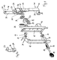
- einen versenkbaren Verschluss in einer schematischen Perspektivdarstellung in einer auseinander gezogenen Ansicht seiner Einzelteile,
- Fig. 1a
- den zum Verschluss gemäß Figur 1 zugehörigen Verriegelungshaken in einer Einzeldarstellung,
- Fig. 2
- den Verschluss gemäß Figur 1 in zusammengebautem Zustand in einer geschnittenen Seitenansicht.
- Fig. 1
- a retractable closure in a schematic perspective view in an exploded view of its individual parts,
- Fig. 1a
- the lock hook according to Figure 1 associated locking hook in a single representation,
- Fig. 2
- the closure of Figure 1 in the assembled state in a sectional side view.
Der in der Zeichnung dargestellte versenkbare Verschluss besteht aus einer in einen Türausschnitt einer nicht weiter dargestellten Tür eines nicht weiter dargestellten Schrankes einzusetzenden und an dem Türblatt festzulegenden Mulde 10, die auf ihrer außenseitig des Türblatts angeordneten Seite eine Einsenkung 11 zur Aufnahme eines darin einklappbaren Hebelgriffes 12 aufweist. Der Hebelgriff 12 ist an der Mulde 10 über ein Schwenklager 13 herausklappbar gelagert, wobei in das Schwenklager 13 eine Feder 14 integriert ist, die den Hebelgriff 12 in seine in die Einsenkung 11 der Mulde 10 eingeklappte Stellung vorspannt.The retractable closure shown in the drawing consists of a recess in a door opening of a non-illustrated door of a cabinet not shown and to be defined on the
An seinem freien, in der Darstellung gemäß Figur 1 unteren Ende ist der Hebelgriff 12 mit einer Schließeinrichtung 15 zum verschließenden Festlegen des Hebelgriffes 12 in der Einsenkung 11 versehen. Hierzu weist der Hebelgriff 12 endseitig ein Gehäuse 17 auf, in welchem ein mittels eines Schlüssels 19 betätigbarer Zylinder 18 angeordnet ist, der die Drehbewegung einer Zunge 20 steuert. Der Hebelgriff 12 ist mit seinem Gehäuse 17 und Zunge 20 in ein an der rückwärtigen Seite der Mulde 10 vorstehendes Gehäuse 16 einklappbar und mittels Drehung der Zunge 20 darin verriegelbar.At its free, in the illustration of Figure 1 lower end of the
Auf der Innenseite des die Mulde 10 tragenden, nicht weiter dargestellten Türblattes ist eine Verriegelungsstange 22 verschiebbar angeordnet, die in einer U-förmigen Stangenführung 26 geführt ist, welche Stangenführung 26 mittels einer Halteleiste 27 formschlüssig an der der Einsenkung 11 abgekehrten Innenfläche der Mulde 10 festlegbar ist. Die Verriegelungsstange 22 trägt einen von ihr abstehenden Arm 23 und weist an ihrem oberen Ende eine Anschlussgestaltung 24 zum Anhängen einer gesonderten Stange zum Verriegeln des Schrankes auf, wie ein derartiges Verriegelungssystem grundsätzlich aus der
Die Verriegelungsstange 22 ist weiterhin mit einer Lochung 28 versehen, in welche die Zähne eines außenverzahnten und an der Innenseite der Mulde 10 drehbar gelagerten Ritzels 29 eingreifen. Der Verriegelungsstange 22 bezüglich der Ritzelanordnung gegenüberliegend ist eine zweite Riegelstange 30 in einer zugeordneten Stangenführung 26 verschiebbar gelagert, wobei die Außenverzahnung des Ritzels 29 in eine entsprechend ausgebildete Lochung der Riegelstange 30 eingreift derart, dass eine Verschiebung der Verriegelungsstange 22 in eine Verschiebung der Riegelstange 30 mit jeweils entgegengesetzter Bewegungsrichtung umsetzbar ist. Die Riegelstange 30 hat in ihrem freien Ende ebenfalls eine Anschlussgestaltung 24, wobei die Riegelstange 30 seitlich verkröpft ist, damit deren Anschlussgestaltung 24 in der gleichen Ebene liegt wie die Anschlussgestaltung der Verriegelungsstange 22.The
Das Verriegelungssystem wird vervollständigt durch einen zwischen der Verriegelungsstange 22 und der Riegelstange 30 angeordneten und in einer Bewegungsrichtung quer zur Verschiebungsrichtung der Stangen 22, 30 drehbeweglichen Verriegelungshaken 33, der mittels eines Drehlagers 34 drehbar an der Mulde 10 gelagert ist. Es ist eine Bügelfeder 35 vorgesehen, die den Verriegelungshaken 33 in dessen Verriegelungsposition vorspannt, in welcher der Verriegelungshaken in an sich bekannter Weise einen Schrankteil, vorzugsweise ein Rahmenteil des die Tür tragenden Schrankes in einer verriegelnden Weise hintergreift.The locking system is completed by an interposed between the
Wie aus Figur la ersichtlich trägt der Verriegelungshaken 33 an seiner der Verriegelungsstange 22 zugewandten Innenseite einen Nocken 36 mit Anlaufschrägen 37. Diesem Nocken 36 des Verriegelungshaken 33 ist an der Verriegelungsstange 22 ein Vorsprung 31 mit daran ausgebildeter Anschrägung 32 derart zugeordnet, dass in der Verriegelungsposition der Verriegelungsstange 22 die Anschrägung 32 des Vorsprungs 31 und die Anlaufschräge 37 des Nockens 36 aneinander anliegen, so dass eine Verschiebung der Verriegelungsstange 22 in deren Freigabestellung (Pfeil 41) eine Verschwenkung des Verriegelungshakens 33 entgegen der Wirkung der Bügelfeder 35 in dessen Freigabeposition herbeiführt.As can be seen from Figure la, the
Zur Betätigung des Verriegelungssystems weist der Hebelgriff 12 an seinem in dem Schwenklager 13 gelagerten Ende einen die Mulde 10 durchgreifenden und in der eingeklappten Stellung des Schwenkhebels 12 in der Einsenkung 11 der Mulde 10 auf dem Arm 23 der Verriegelungsstange 22, und zwar auf dessen der Bewegungsrichtung der Verriegelungsstange 22 in die Verriegelungsposition (Pfeil 40) zugekehrten Seite aufliegenden Ansatz 21 auf. Der Ansatz 21 ist dabei so angeordnet, dass in der eingeklappten Stellung des Hebelgriffes 12 die die Verriegelungsstange 22 vorspannende Feder 25 den Arm 23 der Verriegelungsstange 22 jeweils in Anlage an dem Ansatz 21 hält.For actuation of the locking system, the lever handle 12 at its end mounted in the pivot bearing 13 a
Zum Öffnen des Verschlusses wird nach Betätigung der Schließeinrichtung 15 der Hebelgriff 12 aus der Einsenkung 11 der Mulde 10 herausgeschwenkt. Dabei drückt der Hebelgriff 12 mit seinem Ansatz 21 auf den Arm 23 der Verriegelungsstange 22 und verschiebt diese in deren Freigabestellung in Richtung Pfeil 41. Diese Bewegung der Verriegelungsstange 22 wird über das Ritzel 29 gleichzeitig in eine entsprechende Verschiebung der Riegelstange 30 umgesetzt, so dass auch die Riegelstange 30 in ihre Freigabestellung bewegt wird (Pfeil 41). Wiederum gleichzeitig drückt die Anschrägung 32 des an der Verriegelungsstange 22 angebrachten Vorsprungs 31 auf die Anlaufschräge 37 des Nockens 36 des Verriegelungshakens 33, so dass der Verriegelungshaken durch die Linearverschiebung der Verriegelungsstange 22 in seine Freigabeposition gedreht wird. Nach Erreichen der Öffnungsstellung kann der Hebelgriff 12 losgelassen werden, wobei der Hebelgriff 12 insbesondere durch die Federwirkung der Feder 14 in seine eingeklappte Stellung in der Einsenkung 12 der Mulde 10 zurückgeschwenkt wird. Diese Bewegung wird unterstützt durch die Wirkung der auf den Arm 23 der Verriegelungsstange 22 einwirkenden Feder 25, die die beiden Stangen 22 und 30 in deren Verriegelungsposition zurückführt (Pfeil 40). Wiederum gleichzeitig drückt auch die Bügelfeder 35 den Verriegelungshaken 33 in dessen Verriegelungsposition zurück. Auch in dieser Stellung kann nun die mit dem versenkbaren Verschluss ausgerüstete Tür geschlossen beziehungsweise zugeworfen werden, weil sich die Stangen unabhängig von der Lage des Hebelgriffes in ihre Freigabestellung bewegen können und auch der Verriegelungshaken 33 von der Stangenbewegung entkoppelt ist und somit eigenständig beim Schließen der Tür hin- und herbewegbar ist.To open the shutter, the
Die in der vorstehenden Beschreibung, den Patentansprüchen, der Zusammenfassung und der Zeichnung offenbarten Merkmale des Gegenstandes dieser Unterlagen können einzeln als auch in beliebigen Kombinationen untereinander für die Verwirklichung der Erfindung in ihren verschiedenen Ausführungsformen wesentlich sein.The features disclosed in the foregoing description, the claims, the abstract and the drawings of the subject matter of these documents may be essential individually as well as in any combination with each other for the realization of the invention in its various embodiments.
Claims (6)
Applications Claiming Priority (1)
| Application Number | Priority Date | Filing Date | Title |
|---|---|---|---|
| DE200620014041 DE202006014041U1 (en) | 2006-09-13 | 2006-09-13 | Countersunk closure for doors of thin-walled cupboards has cavity holding lever handle which rests on arm fixed to locking rod with a spring pretensioning locking rod in its extended locking positin |
Publications (2)
| Publication Number | Publication Date |
|---|---|
| EP1900891A2 true EP1900891A2 (en) | 2008-03-19 |
| EP1900891A3 EP1900891A3 (en) | 2009-04-29 |
Family
ID=37514060
Family Applications (1)
| Application Number | Title | Priority Date | Filing Date |
|---|---|---|---|
| EP20070016619 Withdrawn EP1900891A3 (en) | 2006-09-13 | 2007-08-24 | Flap closure lever |
Country Status (3)
| Country | Link |
|---|---|
| US (1) | US7584634B2 (en) |
| EP (1) | EP1900891A3 (en) |
| DE (1) | DE202006014041U1 (en) |
Cited By (2)
| Publication number | Priority date | Publication date | Assignee | Title |
|---|---|---|---|---|
| EP2733286A3 (en) * | 2012-11-19 | 2016-12-07 | EMKA BESCHLAGTEILE GmbH & Co. KG | Pivoting lever closure with low installation depth |
| DE102017119835A1 (en) | 2017-08-29 | 2019-02-28 | Emka Beschlagteile Gmbh & Co. Kg | closure device |
Families Citing this family (8)
| Publication number | Priority date | Publication date | Assignee | Title |
|---|---|---|---|---|
| WO2009115229A1 (en) * | 2008-03-15 | 2009-09-24 | Dirak Dieter Ramsauer Konstruktionselemente Gmbh & Co. Kg | Pivot lever actuation having safety device |
| DE102010015463B4 (en) * | 2010-04-16 | 2014-08-21 | Emka Beschlagteile Gmbh & Co. Kg | Swivel lever lock with rotation prevention for the actuating shaft |
| FR2969684A1 (en) * | 2010-12-27 | 2012-06-29 | Ferco Int Usine Ferrures | Lock fitting i.e. sash-bolt, controlling device for e.g. main sliding leaf of sliding door, has mechanism to transform tilting of lever about axis into rotational movement of square bar about another axis perpendicular to former axis |
| DE202012100971U1 (en) | 2012-03-19 | 2012-07-16 | Emka Beschlagteile Gmbh & Co. Kg | Swivel lever lock with automatically latching cylinder lock |
| US9708833B2 (en) * | 2013-04-09 | 2017-07-18 | Hanchett Entry Systems, Inc. | Swivel lock system with manual override |
| US10422159B2 (en) | 2015-02-23 | 2019-09-24 | Hoffman Enclosures, Inc. | Adjustable rod guide |
| EP3569798A1 (en) * | 2018-05-16 | 2019-11-20 | Industrilås I Nässjö AB | Lift handle arrangement |
| USD980692S1 (en) * | 2022-01-20 | 2023-03-14 | shenzhenshilangtianxiatrading Co,. LTD | Lock |
Citations (7)
| Publication number | Priority date | Publication date | Assignee | Title |
|---|---|---|---|---|
| US4170119A (en) * | 1978-02-06 | 1979-10-09 | The Scott & Fetzer Company Stahl Division | Paddle handle lock bolt |
| US5058937A (en) * | 1991-02-14 | 1991-10-22 | Tri/Mark Corporation | Flush door latch assembly |
| EP0649958A2 (en) * | 1993-10-25 | 1995-04-26 | Corbin Co. | Lock for the secondary leaf of fire doors |
| US5586795A (en) * | 1993-03-01 | 1996-12-24 | Takigen Manufacturing Co. Ltd. | Embedded-type handle assembly |
| DE29917091U1 (en) * | 1999-09-29 | 2001-02-15 | Ramsauer Dieter | Handle lever lock for mounting in a rectangular opening in a thin wall, such as a metal cabinet door |
| DE20107170U1 (en) * | 2001-04-26 | 2002-08-29 | Ramsauer Dieter | Rod lock with lever drive |
| US20040189012A1 (en) * | 2002-11-07 | 2004-09-30 | Piolax Inc. | Lock apparatus |
Family Cites Families (28)
| Publication number | Priority date | Publication date | Assignee | Title |
|---|---|---|---|---|
| US2427386A (en) * | 1944-06-05 | 1947-09-16 | Bassick Co | Door latch |
| US3745796A (en) * | 1971-08-30 | 1973-07-17 | Fleming Metal Fabricators | Lock assembly for metal box |
| US4510779A (en) * | 1982-07-16 | 1985-04-16 | Adams Rite Products, Inc. | Aircraft door lock actuating mechanism |
| US4554807A (en) * | 1983-10-12 | 1985-11-26 | Ardac, Inc. | Door latch mechanism |
| DE3407700C2 (en) * | 1984-03-02 | 1986-10-30 | Rittal-Werk Rudolf Loh Gmbh & Co Kg, 6348 Herborn | Lockable handle for control cabinet doors and the like. |
| DE3673648D1 (en) * | 1986-09-25 | 1990-09-27 | Dieter Ramsauer | PIVOT LEVER LOCK. |
| DE3676823D1 (en) * | 1986-09-25 | 1991-02-14 | Dieter Ramsauer | ROD LOCK FOR SHEET CABINET DOORS. |
| US5970757A (en) * | 1992-12-22 | 1999-10-26 | Ramsauer; Dieter | Swivel lever closing device for doors of housing or cabinets |
| WO1994015049A1 (en) * | 1992-12-22 | 1994-07-07 | Dieter Ramsauer | Closing device for doors of housings or cupboards |
| BR9307730A (en) * | 1992-12-22 | 1999-08-31 | Knuerr Mechanik Ag | Locking device for cabinet or cabinet doors |
| JPH06264655A (en) * | 1993-03-11 | 1994-09-20 | Takigen Seizo Kk | Lock handle device for drawing revolving type door |
| DE4425970C1 (en) * | 1994-07-22 | 1995-11-16 | Emka Beschlagteile | Lowerable closure for left and right-hand hung switchgear cabinet doors |
| JP2623227B2 (en) * | 1994-08-12 | 1997-06-25 | タキゲン製造株式会社 | Push button type flat handle device |
| US5862690A (en) * | 1996-10-04 | 1999-01-26 | Hoffman Enclosures, Inc. | Low profile handle |
| DE29705508U1 (en) | 1997-03-27 | 1997-06-12 | Emka Beschlagteile | Lever lock |
| JP2001519002A (en) * | 1997-03-27 | 2001-10-16 | エムカ ベシユラークタイレ ゲゼルシヤフト ミツト ベシユレンクテル ハフツング ウント コンパニー コマンデイトゲゼルシヤフト | Lever lock |
| DK0972124T3 (en) * | 1997-04-02 | 2003-02-03 | Emka Beschlagteile | Modular rod closing device |
| DE29711741U1 (en) * | 1997-07-04 | 1998-11-05 | Ramsauer Dieter | In the swiveled-in state, the swivel lever can be secured for the closure of control cabinet doors or the like. |
| DE29711737U1 (en) * | 1997-07-04 | 1998-10-29 | Ramsauer Dieter | Padlock visible swivel lever actuation for locking control cabinet doors or the like. |
| DE29711740U1 (en) * | 1997-07-04 | 1998-11-05 | Ramsauer Dieter | Padlock visible swivel lever actuation for locking control cabinet doors or the like. |
| US6341512B1 (en) * | 1997-08-29 | 2002-01-29 | Dieter Ramsauer | Horizontally operated closing device |
| DE29722000U1 (en) * | 1997-12-15 | 1999-04-15 | Ramsauer Dieter | Swivel lever lock for the door, side wall or the like. a control cabinet, a machine panel or the like, with a swivel lever that can be locked with a padlock and / or hook |
| JP2969119B1 (en) * | 1998-12-22 | 1999-11-02 | タキゲン製造株式会社 | Lock handle device for drawer rotation type door |
| AU719207B3 (en) * | 1999-07-16 | 2000-05-04 | Lockwood Security Products Pty Limited | A lock for a sliding window |
| DE20019113U1 (en) * | 2000-11-13 | 2002-04-18 | Ramsauer Dieter | lever Latch |
| JP3522715B2 (en) * | 2001-06-08 | 2004-04-26 | タキゲン製造株式会社 | Lock handle device for sign combination lock built-in type door |
| US7152893B2 (en) * | 2004-08-23 | 2006-12-26 | Key Plastics, Llc | Handle assembly with dual latch feature |
| US7159909B1 (en) * | 2005-11-04 | 2007-01-09 | Kuo-Chuan Hung | Cabinet enclosure handle |
-
2006
- 2006-09-13 DE DE200620014041 patent/DE202006014041U1/en not_active Expired - Lifetime
-
2007
- 2007-08-24 EP EP20070016619 patent/EP1900891A3/en not_active Withdrawn
- 2007-09-13 US US11/855,074 patent/US7584634B2/en not_active Expired - Fee Related
Patent Citations (7)
| Publication number | Priority date | Publication date | Assignee | Title |
|---|---|---|---|---|
| US4170119A (en) * | 1978-02-06 | 1979-10-09 | The Scott & Fetzer Company Stahl Division | Paddle handle lock bolt |
| US5058937A (en) * | 1991-02-14 | 1991-10-22 | Tri/Mark Corporation | Flush door latch assembly |
| US5586795A (en) * | 1993-03-01 | 1996-12-24 | Takigen Manufacturing Co. Ltd. | Embedded-type handle assembly |
| EP0649958A2 (en) * | 1993-10-25 | 1995-04-26 | Corbin Co. | Lock for the secondary leaf of fire doors |
| DE29917091U1 (en) * | 1999-09-29 | 2001-02-15 | Ramsauer Dieter | Handle lever lock for mounting in a rectangular opening in a thin wall, such as a metal cabinet door |
| DE20107170U1 (en) * | 2001-04-26 | 2002-08-29 | Ramsauer Dieter | Rod lock with lever drive |
| US20040189012A1 (en) * | 2002-11-07 | 2004-09-30 | Piolax Inc. | Lock apparatus |
Cited By (2)
| Publication number | Priority date | Publication date | Assignee | Title |
|---|---|---|---|---|
| EP2733286A3 (en) * | 2012-11-19 | 2016-12-07 | EMKA BESCHLAGTEILE GmbH & Co. KG | Pivoting lever closure with low installation depth |
| DE102017119835A1 (en) | 2017-08-29 | 2019-02-28 | Emka Beschlagteile Gmbh & Co. Kg | closure device |
Also Published As
| Publication number | Publication date |
|---|---|
| US7584634B2 (en) | 2009-09-08 |
| EP1900891A3 (en) | 2009-04-29 |
| US20080060392A1 (en) | 2008-03-13 |
| DE202006014041U1 (en) | 2006-11-23 |
Similar Documents
| Publication | Publication Date | Title |
|---|---|---|
| EP1900891A2 (en) | Flap closure lever | |
| DE2611359C2 (en) | Espagnolette lock for door leaves | |
| DE4425970C1 (en) | Lowerable closure for left and right-hand hung switchgear cabinet doors | |
| EP1917413B1 (en) | Multi-point lock for locking doors or wall parts in housings or cupboards | |
| EP0156379B1 (en) | Cash drawer for a cash register | |
| DE102013104078B4 (en) | Bolt lock of a furniture | |
| EP0509217A1 (en) | Door lock with several bolts | |
| DE3645256C2 (en) | Lock for door or window | |
| EP2733286B1 (en) | Pivoting lever closure with low installation depth | |
| EP1739260B1 (en) | Fitting transmission for a window, a door or the like, and method for actuating the transmission | |
| DE102015000606A1 (en) | Locking device for a pivotally mounted wing | |
| DE202011000675U1 (en) | Cabinet, in particular gas bottle cabinet | |
| EP3118401A1 (en) | Lock bolt for the edge of a wing | |
| AT513470B1 (en) | Locks | |
| DE102016112554A1 (en) | Arrangement with a frame for the storage of a sash | |
| EP1790805B1 (en) | Drive with a lever gear for an espagnolette | |
| EP1970513B1 (en) | Semi-fixed wing of a double door and a lock for the semi-fixed wing | |
| AT413044B (en) | HOLDING DEVICE FOR A DRAWER OR DRAWER PUSHER OF A MULTIPLE LOCK | |
| EP1936078A2 (en) | Metal fitting for panic exit device | |
| WO2012119721A2 (en) | Furniture lock | |
| EP0199270A2 (en) | Device for keeping a door or window at least ajar | |
| DE102011003371A1 (en) | Locking arrangement for windows, doors or the like with a pivot bolt | |
| DE10200113B4 (en) | Locks | |
| DE202008015712U1 (en) | furniture lock | |
| DE60209682T2 (en) | Connecting device for extension of the drive rod and the faceplate of a drive rod lock or the like |
Legal Events
| Date | Code | Title | Description |
|---|---|---|---|
| PUAI | Public reference made under article 153(3) epc to a published international application that has entered the european phase |
Free format text: ORIGINAL CODE: 0009012 |
|
| AK | Designated contracting states |
Kind code of ref document: A2 Designated state(s): AT BE BG CH CY CZ DE DK EE ES FI FR GB GR HU IE IS IT LI LT LU LV MC MT NL PL PT RO SE SI SK TR |
|
| AX | Request for extension of the european patent |
Extension state: AL BA HR MK YU |
|
| PUAL | Search report despatched |
Free format text: ORIGINAL CODE: 0009013 |
|
| AK | Designated contracting states |
Kind code of ref document: A3 Designated state(s): AT BE BG CH CY CZ DE DK EE ES FI FR GB GR HU IE IS IT LI LT LU LV MC MT NL PL PT RO SE SI SK TR |
|
| AX | Request for extension of the european patent |
Extension state: AL BA HR MK RS |
|
| AKX | Designation fees paid | ||
| STAA | Information on the status of an ep patent application or granted ep patent |
Free format text: STATUS: THE APPLICATION IS DEEMED TO BE WITHDRAWN |
|
| 18D | Application deemed to be withdrawn |
Effective date: 20091030 |
|
| REG | Reference to a national code |
Ref country code: DE Ref legal event code: 8566 |