EP2199502A2 - Serrure de véhicule automobile - Google Patents
Serrure de véhicule automobile Download PDFInfo
- Publication number
- EP2199502A2 EP2199502A2 EP09014060A EP09014060A EP2199502A2 EP 2199502 A2 EP2199502 A2 EP 2199502A2 EP 09014060 A EP09014060 A EP 09014060A EP 09014060 A EP09014060 A EP 09014060A EP 2199502 A2 EP2199502 A2 EP 2199502A2
- Authority
- EP
- European Patent Office
- Prior art keywords
- bending
- functional element
- motor vehicle
- lever
- functional
- Prior art date
- Legal status (The legal status is an assumption and is not a legal conclusion. Google has not performed a legal analysis and makes no representation as to the accuracy of the status listed.)
- Granted
Links
Images


Classifications
-
- E—FIXED CONSTRUCTIONS
- E05—LOCKS; KEYS; WINDOW OR DOOR FITTINGS; SAFES
- E05B—LOCKS; ACCESSORIES THEREFOR; HANDCUFFS
- E05B85/00—Details of vehicle locks not provided for in groups E05B77/00 - E05B83/00
- E05B85/20—Bolts or detents
- E05B85/24—Bolts rotating about an axis
- E05B85/243—Bolts rotating about an axis with a bifurcated bolt
-
- E—FIXED CONSTRUCTIONS
- E05—LOCKS; KEYS; WINDOW OR DOOR FITTINGS; SAFES
- E05B—LOCKS; ACCESSORIES THEREFOR; HANDCUFFS
- E05B15/00—Other details of locks; Parts for engagement by bolts of fastening devices
- E05B15/0053—Other details of locks; Parts for engagement by bolts of fastening devices means providing a stable, i.e. indexed, position of lock parts
-
- E—FIXED CONSTRUCTIONS
- E05—LOCKS; KEYS; WINDOW OR DOOR FITTINGS; SAFES
- E05B—LOCKS; ACCESSORIES THEREFOR; HANDCUFFS
- E05B15/00—Other details of locks; Parts for engagement by bolts of fastening devices
- E05B15/04—Spring arrangements in locks
- E05B2015/0496—Springs actuated by cams or the like
-
- E—FIXED CONSTRUCTIONS
- E05—LOCKS; KEYS; WINDOW OR DOOR FITTINGS; SAFES
- E05B—LOCKS; ACCESSORIES THEREFOR; HANDCUFFS
- E05B15/00—Other details of locks; Parts for engagement by bolts of fastening devices
- E05B15/16—Use of special materials for parts of locks
- E05B2015/1692—Wires or straps
-
- E—FIXED CONSTRUCTIONS
- E05—LOCKS; KEYS; WINDOW OR DOOR FITTINGS; SAFES
- E05B—LOCKS; ACCESSORIES THEREFOR; HANDCUFFS
- E05B77/00—Vehicle locks characterised by special functions or purposes
- E05B77/22—Functions related to actuation of locks from the passenger compartment of the vehicle
- E05B77/30—Functions related to actuation of locks from the passenger compartment of the vehicle allowing opening by means of an inner door handle, even if the door is locked
Definitions
- the invention relates to a motor vehicle lock according to the preamble of claim 1 and a motor vehicle lock according to the preamble of claim 2.
- the motor vehicle lock in question finds application in all types of closure elements of a motor vehicle. These include in particular side doors, rear doors, tailgates, trunk lids or hoods. In principle, these closure elements can also be designed in the manner of sliding doors.
- the known motor vehicle lock ( DE 1 553 299 A1 ), from which the invention proceeds, is designed as a purely mechanical lock. This means that electric motors, for example, for setting functional states, are not provided.
- the well-known motor vehicle lock is equipped with the closing elements lock latch and pawl.
- the latch can be brought in a conventional manner in an open position, in a main closed position and in a Vorschsted ein.
- the pawl has the task of holding the latch in the two closed positions. To release the latch, the pawl can be manually lifted.
- the known motor vehicle lock is further equipped with a lock mechanism that can be switched to different functional states. These are the functional states “unlocked” and “locked”. In the functional state “unlocked”, the associated motor vehicle door can be opened by actuating the inside door handle and the outside door handle. In the functional state “locked” can not be opened from the outside, but from the inside.
- the lock mechanism is equipped with a coupling arrangement in which a coupling pin cooperates with different control slots.
- the invention is based on the problem, the known motor vehicle lock in such a way and further develop that the structure of the arrangement is generally simpler and more compact.
- the functional element relevant for the realization of the different functional states of the lock mechanism can be designed in the manner of a resiliently flexible wire or strip.
- a functional element is referred to below as a bending functional element.
- the term "wire" refers to the shape, not the material of the element.
- the adjustment of the bending-functional element in the different functional positions is here simply a corresponding bending, so deflecting the bending-functional element back.
- On a bearing or guide element can be dispensed with.
- a control lever pivotable about a control lever axis is provided with a control contour, wherein the control contour is engaged or engageable with at least one bending functional element for its deflection.
- a control contour basically has a longitudinal extent and a vertical extent, wherein the height of the control contour varies along its longitudinal extent for realizing the control function.
- the control function here is to adjust the bending functional element in the respective desired functional position.
- the bending functional element provides a part of a tilt spring arrangement for the control lever. This dual use of the bending functional element leads to a simplification of the structural design, which is associated with corresponding cost advantages.
- the bending functional element is equipped with two legs for the realization of the above two functions, which leads to a particularly simple implementation of the bending functional element.
- the closing elements lock latch 1 and pawl 2, each in the closed position, shows Fig. 1 .
- Essential here is the fact that the pawl 2 in Fig. 1 can be lifted by pivoting clockwise, so that the latch 1 can fall into the open position.
- the latch 1 acts in the usual way with a closing wedge o. The like. Together, which is regularly arranged on the door of the motor vehicle.
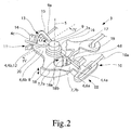
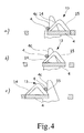
- the Fig. 2 to 4 relate to the lock mechanism 3 of the proposed motor vehicle lock, which here and preferably only in the functional states “unlocked” and “locked” can be brought.
- the lock mechanism 3 ensures that the pawl 2, depending on the functional state by an operation of the outside door handle and / or the door inner handle or just not liftable.
- this has at least one functional element 4 which can be adjusted into corresponding functional positions.
- the functional element 4 or the Functional elements can bring the lock mechanism 3 so in the desired functional states.
- the functional element 4 shown in the illustrated embodiment is designed in the manner of a resiliently flexible wire and so as a bending functional element 4 is resiliently engageable in the different functional positions.
- Fig. 3a ) and c) are shown two functional positions to be explained.
- a synopsis of Fig. 2 and 3 shows that the adjustment of the bending functional element 4 is due to a resilient bending of the same. This effect and the triggering of this adjustment will be explained in detail below.
- At least one of the functional elements 4 is designed as a bending functional element 4.
- Other functional elements can be designed in the usual way with displaceable coupling pins or the like.
- a control lever 6 pivotable about a control lever axis 5 is provided with a control contour 7, wherein the control contour 7 is engaged or engageable with at least one bending functional element 4 for adjusting it.
- the course of the control contour 7 can best be a synopsis of Fig. 2 and 3 remove.
- the decisive for the adjustment of the bending-functional element 4 height extension 8 of the control contour 7 is aligned parallel to the control lever axis 5. This is shown in the illustration Fig. 2 ,
- the operating states "unlocked” and “locked” can be adjusted with an adjustment of the control lever 6.
- the motor vehicle lock is designed as a purely mechanical lock. This means that electric motor drives are not provided for the setting of functional states. Basically, it is conceivable to use an electric motor drive for the adjustment of the control lever 6.
- the inner securing element is regularly an inner securing button which is integrated into the inner door lining.
- the control lever 6 is equipped with corresponding coupling points 9, 10 for the inner securing element on the one hand and the lock cylinder on the other.
- the coupling point 10 of the lock cylinder is equipped with a freewheel, so that an adjustment of the inner securing element is not necessarily connected to an adjustment of the lock cylinder.
- the respective coupling point 9, 10 is coupled via a corresponding Bowden cable 9a, 10a or via a corresponding rod with the inner securing element or with the lock cylinder.
- the adjustment of the bending functional element 4 In an adjustment of the control lever 6 in Fig. 2 To the left, the control contour 7 engages with the bending functional element 4 and deflects the bending functional element 4 in a direction substantially parallel to the control lever axis 5, in FIG Fig. 2 up, out. It is the case here that the bending-functional element 4 first comes into engagement with the control contour 7 during the adjustment of the control lever 6. In principle, however, it is conceivable that the bending-functional element 4 is always in engagement with the control contour 7.
- control contour 7 preferably extends substantially along a circular path, which is aligned with the control lever axis 5. This is, as here and preferably provided, particularly advantageous when the control contour 7 associated portion of the bending-functional element 4 relative to the control lever axis 5 extends substantially radially. Then, the above, substantially vertical alignment of the control contour 7 is ensured to the bending functional element 4.
- control contour 7 is designed substantially web-shaped, wherein the height extension 8 of the web-shaped configuration is provided substantially parallel to the control lever axis 5.
- the control contour 7 has a raised portion 7a for deflecting the bending functional element 4, wherein the raised portion 7a is preferably followed by a run-on slope 7b, via which the bending functional element 4 in an adjustment of the control lever 6 in engagement with the raised portion 7a comes.
- the interaction of the run-on slope 7b with the bending functional element 4 can be seen in FIG Fig. 3b ) remove.
- the proposed solution is characterized in that all necessary for a mechanical motor vehicle lock functions are particularly compact feasible.
- This also includes the realization of a tilt spring assembly 11 for the control lever 6, which biases the control lever 6 depending on the position of the control lever 6 in one of two end positions or holds in one of two end positions.
- more than two end positions can be provided in the above sense, for example, if in addition to the functional states “locked” and “unlocked” and the functional state "anti-theft” o. The like. Is to be realized.
- the bending functional element 4 provides a part of the tilt spring arrangement 11.
- the bending functional element 4 is thus used twice.
- the tilt spring arrangement 11 has a spring element 12 and a spring deflecting element 13, wherein the bending functional element 4 here provides the spring element 12.
- the Kippfederan extract 11 acts once against the adjustment.
- the control lever 6 is preferably provided with two lever arms 6a, 6b, one lever arm 6a having the control contour 6 and the other lever arm 6b having the spring deflecting element 13.
- the control contour 7 associated lever arm 6a is equipped with the coupling point 10 for the lock cylinder and the Federauslenkelement 13 associated lever arm 6b with the coupling point 9 for the inner securing element. It thus results not only a multiple use of the bending functional element 4, but also a multiple use of the control lever 6, which leads to a further increase in compactness.
- the control lever 6 is preferably designed as a plastic or sheet metal part, wherein the control contour 7 and the Federausschelement 13 regardless of the choice of material here and preferably integral components of the control lever 6. In principle, it can also be provided that one of these components 7, 13 are attached to the control lever 6, for example.
- the bending functional element 4 is constructed similar to a leg spring. It is preferably such that the bending-functional element 4 has two legs 4a, 4b, wherein the one leg 4a of the control contour 7 and the other leg 4b of the tilt spring arrangement 11 is assigned. It is further preferred that the one leg 4a is arranged on the one lever arm 6a and the other leg 4b on the other lever arm 6b.
- the arrangement of the bending-functional element 4 on the two lever arms 6a, 6b leads here in an advantageous manner to that the two legs 4a, 4b of the bending-functional element 4 extend in substantially opposite directions.
- the bending-functional element 4 at one end attached to the housing of the motor vehicle lock, in particular clamped on the housing or be embedded in the housing.
- the spring coils 16 of the bending-functional element 4 are placed on the pawl 2 and the control lever 6 associated bearing pin 2 a.
- the control contour 7 associated leg 4a is biased against a stop 4c, which is the Federausschelement 13 associated leg 4b against a stop 4d. Together with the placement of the spring coils 16 on the pawl 2 and the control lever 6 associated bearing pin 2 a total of simple and therefore cost-effective definition of the bending-functional element 4 has been realized.
- Fig. 2 It can be the representation in Fig. 2 can be seen that the bending-functional element 4 is bent to its adjustment in the above functional positions substantially to a geometric bending axis, which is perpendicular to the longitudinal extent at least part of the bending functional element 4 is aligned.
- the bending functional element 4 consists of a metal material, preferably spring steel. But it may also be advantageous to design the bending functional element 3 in a plastic material.
- the bending functional element 4 has a circular cross-section.
- the bending-functional element 4 is designed strip-shaped or strip-shaped, since such elements can be fastened in a simple manner.
- the bending functional element 4 is configured in sections straight. Depending on the application, it may also be advantageous that the bending functional element 4 is adapted to the structural conditions and deviates considerably from a straight configuration.
- the bending-functional element 4 is formed as a one-piece wire, which has the same spring-elastic properties over its entire length.
- the bending-functional element 4 is resiliently bendable only in sections and, moreover, rather rigid. This can be achieved, for example, by changing the wire cross-section over the length of the wire.
- a simple realization of the bending-functional element 4 can be achieved in that the bending-functional element 4 is designed in the manner of a bending beam.
- the term "bending beam” is to be understood here broadly. What is meant is that the bending functional element 4 is fixed at a position from which the adjustable part of the bending functional element 4 extends. After this broad understanding and the bending functional element 4 shown in the drawing is designed in the manner of a bending beam. Strictly speaking, this is Embodiment of course realized two bending beams, which go back to the two legs 4a, 4b of the bending functional element 4.
- the bending functional element 4 can serve as an actuating element, for example for a coupling.
- the bending functional element 4 itself provides a switchable coupling between pivotable adjusting elements 2, 17 of the motor vehicle lock. This will be explained in detail below with reference to the concrete functional positions of the lock mechanism 3.
- the bending-functional element 4 is in a first functional position in engagement with the adjusting elements 2, 17 and can be brought and the adjusting elements 2, 17 couples and in a second functional position out of engagement of at least one adjusting element 2, 17 and the adjusting elements 2, 17 decoupled.
- adjusting element 17 with the adjusting element 2 - pawl 2 - are coupled.
- the bending functional element 4 in a functional position can also act blockingly on an adjusting element of the lock mechanism 3. Then it is preferably such that the blocking force acts perpendicular to the extension of the bending functional element 4.
- the adjusting elements 2, 17 mentioned above are, on the one hand, the pawl 2 and, on the other hand, the external operating lever 17 of the lock mechanism 3.
- An internal operating lever is not shown in the drawing, but is provided. This will be explained later.
- the pawl 2, the control lever 6 and the outer actuating lever 17 are pivotable about the same pivot axis 5. This preferably also applies to the internal operating lever, not shown. It is also conceivable that only two of these levers are pivotable about the same pivot axis. It is conceivable, finally, that a part of these levers are pivotable about mutually parallel pivot axes.
- the pawl 2 or a lever coupled to the pawl 2 has a pawl driver contour 18, wherein further preferably the external actuating lever 17 or one with the external actuating lever 17th coupled lever has an external actuating cam contour 19.
- the arrangement is preferably made such that when in the functional position "unlocked" befindlichem bending functional element 4 of the external actuating lever 17 via the external actuating driver contour 19, the bending functional element 4 and the pawl driver contour 18 is coupled to the pawl 2. This functional position is in Fig. 2 shown.
- the pawl driver contour 18 consists of two bearing blocks 18a, 18b, between which the outer actuating driver contour 19 in the functional position "locked” passes ( Fig. 3c )). This has the advantage that the bending-functional element 4 is optimally supported at the point of engagement at which the actuating force is transmitted yes.
- an internal operating lever is provided.
- This inner operating lever cooperates with the pawl 2 and the bending functional element 4 in the same way as the external operating lever.
- the internal operating lever is provided with an internal operating driver contour, which runs parallel to the external actuating driver contour 19 accordingly.
- the internal operating lever is equipped with an override section which in the functional state "unlocked” upon actuation of the internal operating lever in engagement with an override section 20 on the control lever comes, causing the joystick in Fig. 2 is adjusted to the right. This in turn leads to an adjustment of the bending-functional element 4 in the functional position "unlocked”. This is called the "override function”.
- the proposed motor vehicle lock can be used for all possible closing elements of a motor vehicle.
- Preferred examples are a side door, a tailgate, a trunk lid or a hood of a motor vehicle.
Landscapes
- Lock And Its Accessories (AREA)
Applications Claiming Priority (1)
| Application Number | Priority Date | Filing Date | Title |
|---|---|---|---|
| DE200820016705 DE202008016705U1 (de) | 2008-12-18 | 2008-12-18 | Kraftfahrzeugschloss |
Publications (3)
| Publication Number | Publication Date |
|---|---|
| EP2199502A2 true EP2199502A2 (fr) | 2010-06-23 |
| EP2199502A3 EP2199502A3 (fr) | 2014-02-26 |
| EP2199502B1 EP2199502B1 (fr) | 2016-10-19 |
Family
ID=42034491
Family Applications (1)
| Application Number | Title | Priority Date | Filing Date |
|---|---|---|---|
| EP09014060.9A Not-in-force EP2199502B1 (fr) | 2008-12-18 | 2009-11-10 | Serrure de véhicule automobile |
Country Status (2)
| Country | Link |
|---|---|
| EP (1) | EP2199502B1 (fr) |
| DE (1) | DE202008016705U1 (fr) |
Cited By (3)
| Publication number | Priority date | Publication date | Assignee | Title |
|---|---|---|---|---|
| EP2518246A3 (fr) * | 2011-04-27 | 2014-12-17 | Brose Schliesssysteme GmbH & Co. KG | Serrure de véhicule automobile |
| US9074393B2 (en) * | 2008-09-21 | 2015-07-07 | Brose Schliesssysteme Gmbh & Co. Kg | Motor vehicle lock |
| EP2636827A3 (fr) * | 2012-03-06 | 2016-11-30 | Brose Schliesssysteme GmbH & Co. KG | Serrure de véhicule automobile |
Families Citing this family (2)
| Publication number | Priority date | Publication date | Assignee | Title |
|---|---|---|---|---|
| WO2015113527A1 (fr) * | 2014-01-28 | 2015-08-06 | Kiekert Aktiengesellschaft | Serrure de portière de véhicule à moteur |
| US11555335B2 (en) * | 2018-07-20 | 2023-01-17 | Inteva Products, Llc | Vehicle latch with double pull release |
Citations (1)
| Publication number | Priority date | Publication date | Assignee | Title |
|---|---|---|---|---|
| DE1553299A1 (de) | 1966-01-28 | 1971-11-25 | Bocklenberg & Motte Bomoro | Drehfallenschloss fuer Kraftfahrzeugtueren |
Family Cites Families (6)
| Publication number | Priority date | Publication date | Assignee | Title |
|---|---|---|---|---|
| DE29804649U1 (de) * | 1998-03-14 | 1998-05-14 | Schlos Und Metallwarenfabrik B | Motorhaubenverschluß für ein Kraftfahrzeug |
| DE10043574A1 (de) * | 2000-05-19 | 2001-11-22 | Witte Velbert Gmbh & Co Kg | Antriebsanordnung für insbesondere ein nockengesteuertes Drehfallenschloß |
| DE10356292A1 (de) * | 2003-11-28 | 2005-06-23 | Brose Schließsysteme GmbH & Co.KG | Kraftfahrzeugschloß |
| EP1580366A3 (fr) * | 2004-03-23 | 2009-10-28 | Brose Schliesssysteme GmbH & Co. KG | Serrure pour véhicule automobile |
| DE102005029079B9 (de) * | 2005-06-23 | 2019-10-10 | Witte-Velbert Gmbh & Co. Kg | Drehfallenverschluss |
| DE102005048945A1 (de) * | 2005-10-13 | 2007-04-19 | Valeo Sicherheitssysteme Gmbh | Schließhilfe zum Verschließen einer Fahrzeugtür |
-
2008
- 2008-12-18 DE DE200820016705 patent/DE202008016705U1/de not_active Expired - Lifetime
-
2009
- 2009-11-10 EP EP09014060.9A patent/EP2199502B1/fr not_active Not-in-force
Patent Citations (1)
| Publication number | Priority date | Publication date | Assignee | Title |
|---|---|---|---|---|
| DE1553299A1 (de) | 1966-01-28 | 1971-11-25 | Bocklenberg & Motte Bomoro | Drehfallenschloss fuer Kraftfahrzeugtueren |
Cited By (4)
| Publication number | Priority date | Publication date | Assignee | Title |
|---|---|---|---|---|
| US9074393B2 (en) * | 2008-09-21 | 2015-07-07 | Brose Schliesssysteme Gmbh & Co. Kg | Motor vehicle lock |
| EP2518246A3 (fr) * | 2011-04-27 | 2014-12-17 | Brose Schliesssysteme GmbH & Co. KG | Serrure de véhicule automobile |
| US8967678B2 (en) | 2011-04-27 | 2015-03-03 | Brose Schliesssysteme Gmbh & Co. Kg | Motor vehicle lock |
| EP2636827A3 (fr) * | 2012-03-06 | 2016-11-30 | Brose Schliesssysteme GmbH & Co. KG | Serrure de véhicule automobile |
Also Published As
| Publication number | Publication date |
|---|---|
| EP2199502B1 (fr) | 2016-10-19 |
| DE202008016705U1 (de) | 2010-05-12 |
| EP2199502A3 (fr) | 2014-02-26 |
Similar Documents
| Publication | Publication Date | Title |
|---|---|---|
| EP2342405B1 (fr) | Verrou pour véhicule à moteur | |
| EP2420642B1 (fr) | Serrure de véhicule automobile | |
| DE102008018500A1 (de) | Kraftfahrzeugschloß | |
| EP3173554B1 (fr) | Serrure de véhicule automobile | |
| DE10041498B4 (de) | Schließeinrichtung für eine Fahrzeugtür | |
| EP2199502B1 (fr) | Serrure de véhicule automobile | |
| DE202010009333U1 (de) | Kraftfahrzeugschloss | |
| EP2362041A1 (fr) | Verrouillage de protection contre les mines pour l'agencement sur des portes de véhicules militaires | |
| EP2166181B1 (fr) | Entraînement de commande pour une serrure de véhicule automobile | |
| EP3059362A1 (fr) | Serrure de véhicule automobile | |
| EP1791709A1 (fr) | Vehicule cabriolet | |
| DE19924028A1 (de) | Kraftfahrzeugtür | |
| DE202007013330U1 (de) | Kraftfahrzeugschloß | |
| EP1772577A2 (fr) | Serrure pour véhicule automobile | |
| DE10392820B4 (de) | Verfahren zum Herstellen eines Schlosses eines Kraftfahrzeuges | |
| EP1625961B1 (fr) | Dispositif de palier pour un élément de roulement | |
| DE102008039442A1 (de) | Kfz-Fronthaubenschloss | |
| DE102005023224B4 (de) | Betätigungsvorrichtung für Fanghaken einer Fronthaube | |
| DE102004034529B3 (de) | Elektromechanisches Türschloss | |
| DE10129112B4 (de) | Türgriff für Automobile | |
| DE102013219734B3 (de) | Verriegelungseinheit für einen fahrzeugsitz und fahrzeugsitz | |
| DE102010026764A1 (de) | Betätigungseinrichtung für eine Verriegelungsvorrichtung eines Kraftwagens | |
| DE202010011048U1 (de) | Kraftfahrzeugschloss | |
| DE102010050015A1 (de) | Feststellvorrichtung für verstellbare Kraftfahrzeuglenksäule | |
| DE3642242A1 (de) | Verriegelungseinrichtung fuer tueren, hauben, klappen o.dgl. von fahrzeugen, insbesondere kraftfahrzeugen |
Legal Events
| Date | Code | Title | Description |
|---|---|---|---|
| PUAI | Public reference made under article 153(3) epc to a published international application that has entered the european phase |
Free format text: ORIGINAL CODE: 0009012 |
|
| AK | Designated contracting states |
Kind code of ref document: A2 Designated state(s): AT BE BG CH CY CZ DE DK EE ES FI FR GB GR HR HU IE IS IT LI LT LU LV MC MK MT NL NO PL PT RO SE SI SK SM TR |
|
| AX | Request for extension of the european patent |
Extension state: AL BA RS |
|
| RIC1 | Information provided on ipc code assigned before grant |
Ipc: E05B 65/32 20060101AFI20130916BHEP |
|
| PUAL | Search report despatched |
Free format text: ORIGINAL CODE: 0009013 |
|
| AK | Designated contracting states |
Kind code of ref document: A3 Designated state(s): AT BE BG CH CY CZ DE DK EE ES FI FR GB GR HR HU IE IS IT LI LT LU LV MC MK MT NL NO PL PT RO SE SI SK SM TR |
|
| AX | Request for extension of the european patent |
Extension state: AL BA RS |
|
| 17P | Request for examination filed |
Effective date: 20140826 |
|
| RBV | Designated contracting states (corrected) |
Designated state(s): AT BE BG CH CY CZ DE DK EE ES FI FR GB GR HR HU IE IS IT LI LT LU LV MC MK MT NL NO PL PT RO SE SI SK SM TR |
|
| RIC1 | Information provided on ipc code assigned before grant |
Ipc: E05B 15/16 20060101ALN20151214BHEP Ipc: E05B 15/00 20060101ALI20151214BHEP Ipc: E05B 85/24 20140101AFI20151214BHEP Ipc: E05B 77/30 20140101ALN20151214BHEP Ipc: E05B 15/04 20060101ALN20151214BHEP |
|
| GRAP | Despatch of communication of intention to grant a patent |
Free format text: ORIGINAL CODE: EPIDOSNIGR1 |
|
| INTG | Intention to grant announced |
Effective date: 20160323 |
|
| GRAJ | Information related to disapproval of communication of intention to grant by the applicant or resumption of examination proceedings by the epo deleted |
Free format text: ORIGINAL CODE: EPIDOSDIGR1 |
|
| REG | Reference to a national code |
Ref country code: DE Ref legal event code: R079 Ref document number: 502009013240 Country of ref document: DE Free format text: PREVIOUS MAIN CLASS: E05B0065320000 Ipc: E05B0085240000 |
|
| GRAP | Despatch of communication of intention to grant a patent |
Free format text: ORIGINAL CODE: EPIDOSNIGR1 |
|
| INTG | Intention to grant announced |
Effective date: 20160805 |
|
| RIC1 | Information provided on ipc code assigned before grant |
Ipc: E05B 15/16 20060101ALN20160728BHEP Ipc: E05B 77/30 20140101ALN20160728BHEP Ipc: E05B 15/00 20060101ALI20160728BHEP Ipc: E05B 15/04 20060101ALN20160728BHEP Ipc: E05B 85/24 20140101AFI20160728BHEP |
|
| GRAS | Grant fee paid |
Free format text: ORIGINAL CODE: EPIDOSNIGR3 |
|
| GRAA | (expected) grant |
Free format text: ORIGINAL CODE: 0009210 |
|
| AK | Designated contracting states |
Kind code of ref document: B1 Designated state(s): AT BE BG CH CY CZ DE DK EE ES FI FR GB GR HR HU IE IS IT LI LT LU LV MC MK MT NL NO PL PT RO SE SI SK SM TR |
|
| REG | Reference to a national code |
Ref country code: GB Ref legal event code: FG4D Free format text: NOT ENGLISH |
|
| REG | Reference to a national code |
Ref country code: CH Ref legal event code: EP |
|
| REG | Reference to a national code |
Ref country code: AT Ref legal event code: REF Ref document number: 838500 Country of ref document: AT Kind code of ref document: T Effective date: 20161115 |
|
| REG | Reference to a national code |
Ref country code: IE Ref legal event code: FG4D Free format text: LANGUAGE OF EP DOCUMENT: GERMAN |
|
| REG | Reference to a national code |
Ref country code: DE Ref legal event code: R096 Ref document number: 502009013240 Country of ref document: DE |
|
| REG | Reference to a national code |
Ref country code: NL Ref legal event code: MP Effective date: 20161019 |
|
| REG | Reference to a national code |
Ref country code: LT Ref legal event code: MG4D |
|
| PG25 | Lapsed in a contracting state [announced via postgrant information from national office to epo] |
Ref country code: BE Free format text: LAPSE BECAUSE OF NON-PAYMENT OF DUE FEES Effective date: 20161130 Ref country code: LV Free format text: LAPSE BECAUSE OF FAILURE TO SUBMIT A TRANSLATION OF THE DESCRIPTION OR TO PAY THE FEE WITHIN THE PRESCRIBED TIME-LIMIT Effective date: 20161019 |
|
| PG25 | Lapsed in a contracting state [announced via postgrant information from national office to epo] |
Ref country code: SE Free format text: LAPSE BECAUSE OF FAILURE TO SUBMIT A TRANSLATION OF THE DESCRIPTION OR TO PAY THE FEE WITHIN THE PRESCRIBED TIME-LIMIT Effective date: 20161019 Ref country code: LT Free format text: LAPSE BECAUSE OF FAILURE TO SUBMIT A TRANSLATION OF THE DESCRIPTION OR TO PAY THE FEE WITHIN THE PRESCRIBED TIME-LIMIT Effective date: 20161019 Ref country code: GR Free format text: LAPSE BECAUSE OF FAILURE TO SUBMIT A TRANSLATION OF THE DESCRIPTION OR TO PAY THE FEE WITHIN THE PRESCRIBED TIME-LIMIT Effective date: 20170120 Ref country code: NO Free format text: LAPSE BECAUSE OF FAILURE TO SUBMIT A TRANSLATION OF THE DESCRIPTION OR TO PAY THE FEE WITHIN THE PRESCRIBED TIME-LIMIT Effective date: 20170119 |
|
| PG25 | Lapsed in a contracting state [announced via postgrant information from national office to epo] |
Ref country code: FI Free format text: LAPSE BECAUSE OF FAILURE TO SUBMIT A TRANSLATION OF THE DESCRIPTION OR TO PAY THE FEE WITHIN THE PRESCRIBED TIME-LIMIT Effective date: 20161019 Ref country code: ES Free format text: LAPSE BECAUSE OF FAILURE TO SUBMIT A TRANSLATION OF THE DESCRIPTION OR TO PAY THE FEE WITHIN THE PRESCRIBED TIME-LIMIT Effective date: 20161019 Ref country code: NL Free format text: LAPSE BECAUSE OF FAILURE TO SUBMIT A TRANSLATION OF THE DESCRIPTION OR TO PAY THE FEE WITHIN THE PRESCRIBED TIME-LIMIT Effective date: 20161019 Ref country code: PL Free format text: LAPSE BECAUSE OF FAILURE TO SUBMIT A TRANSLATION OF THE DESCRIPTION OR TO PAY THE FEE WITHIN THE PRESCRIBED TIME-LIMIT Effective date: 20161019 Ref country code: PT Free format text: LAPSE BECAUSE OF FAILURE TO SUBMIT A TRANSLATION OF THE DESCRIPTION OR TO PAY THE FEE WITHIN THE PRESCRIBED TIME-LIMIT Effective date: 20170220 Ref country code: IS Free format text: LAPSE BECAUSE OF FAILURE TO SUBMIT A TRANSLATION OF THE DESCRIPTION OR TO PAY THE FEE WITHIN THE PRESCRIBED TIME-LIMIT Effective date: 20170219 Ref country code: HR Free format text: LAPSE BECAUSE OF FAILURE TO SUBMIT A TRANSLATION OF THE DESCRIPTION OR TO PAY THE FEE WITHIN THE PRESCRIBED TIME-LIMIT Effective date: 20161019 |
|
| REG | Reference to a national code |
Ref country code: DE Ref legal event code: R119 Ref document number: 502009013240 Country of ref document: DE |
|
| REG | Reference to a national code |
Ref country code: CH Ref legal event code: PL |
|
| PG25 | Lapsed in a contracting state [announced via postgrant information from national office to epo] |
Ref country code: SK Free format text: LAPSE BECAUSE OF FAILURE TO SUBMIT A TRANSLATION OF THE DESCRIPTION OR TO PAY THE FEE WITHIN THE PRESCRIBED TIME-LIMIT Effective date: 20161019 Ref country code: RO Free format text: LAPSE BECAUSE OF FAILURE TO SUBMIT A TRANSLATION OF THE DESCRIPTION OR TO PAY THE FEE WITHIN THE PRESCRIBED TIME-LIMIT Effective date: 20161019 Ref country code: CZ Free format text: LAPSE BECAUSE OF FAILURE TO SUBMIT A TRANSLATION OF THE DESCRIPTION OR TO PAY THE FEE WITHIN THE PRESCRIBED TIME-LIMIT Effective date: 20161019 Ref country code: MC Free format text: LAPSE BECAUSE OF FAILURE TO SUBMIT A TRANSLATION OF THE DESCRIPTION OR TO PAY THE FEE WITHIN THE PRESCRIBED TIME-LIMIT Effective date: 20161019 Ref country code: EE Free format text: LAPSE BECAUSE OF FAILURE TO SUBMIT A TRANSLATION OF THE DESCRIPTION OR TO PAY THE FEE WITHIN THE PRESCRIBED TIME-LIMIT Effective date: 20161019 Ref country code: LI Free format text: LAPSE BECAUSE OF NON-PAYMENT OF DUE FEES Effective date: 20161130 Ref country code: DK Free format text: LAPSE BECAUSE OF FAILURE TO SUBMIT A TRANSLATION OF THE DESCRIPTION OR TO PAY THE FEE WITHIN THE PRESCRIBED TIME-LIMIT Effective date: 20161019 Ref country code: CH Free format text: LAPSE BECAUSE OF NON-PAYMENT OF DUE FEES Effective date: 20161130 |
|
| REG | Reference to a national code |
Ref country code: IE Ref legal event code: MM4A |
|
| PLBE | No opposition filed within time limit |
Free format text: ORIGINAL CODE: 0009261 |
|
| REG | Reference to a national code |
Ref country code: FR Ref legal event code: ST Effective date: 20170731 |
|
| STAA | Information on the status of an ep patent application or granted ep patent |
Free format text: STATUS: NO OPPOSITION FILED WITHIN TIME LIMIT |
|
| PG25 | Lapsed in a contracting state [announced via postgrant information from national office to epo] |
Ref country code: SM Free format text: LAPSE BECAUSE OF FAILURE TO SUBMIT A TRANSLATION OF THE DESCRIPTION OR TO PAY THE FEE WITHIN THE PRESCRIBED TIME-LIMIT Effective date: 20161019 Ref country code: BG Free format text: LAPSE BECAUSE OF FAILURE TO SUBMIT A TRANSLATION OF THE DESCRIPTION OR TO PAY THE FEE WITHIN THE PRESCRIBED TIME-LIMIT Effective date: 20170119 Ref country code: IT Free format text: LAPSE BECAUSE OF FAILURE TO SUBMIT A TRANSLATION OF THE DESCRIPTION OR TO PAY THE FEE WITHIN THE PRESCRIBED TIME-LIMIT Effective date: 20161019 |
|
| 26N | No opposition filed |
Effective date: 20170720 |
|
| GBPC | Gb: european patent ceased through non-payment of renewal fee |
Effective date: 20170119 |
|
| PG25 | Lapsed in a contracting state [announced via postgrant information from national office to epo] |
Ref country code: LU Free format text: LAPSE BECAUSE OF NON-PAYMENT OF DUE FEES Effective date: 20161130 |
|
| PG25 | Lapsed in a contracting state [announced via postgrant information from national office to epo] |
Ref country code: FR Free format text: LAPSE BECAUSE OF NON-PAYMENT OF DUE FEES Effective date: 20161219 |
|
| PG25 | Lapsed in a contracting state [announced via postgrant information from national office to epo] |
Ref country code: GB Free format text: LAPSE BECAUSE OF NON-PAYMENT OF DUE FEES Effective date: 20170119 Ref country code: DE Free format text: LAPSE BECAUSE OF NON-PAYMENT OF DUE FEES Effective date: 20170601 Ref country code: SI Free format text: LAPSE BECAUSE OF FAILURE TO SUBMIT A TRANSLATION OF THE DESCRIPTION OR TO PAY THE FEE WITHIN THE PRESCRIBED TIME-LIMIT Effective date: 20161019 Ref country code: IE Free format text: LAPSE BECAUSE OF NON-PAYMENT OF DUE FEES Effective date: 20161110 |
|
| REG | Reference to a national code |
Ref country code: AT Ref legal event code: MM01 Ref document number: 838500 Country of ref document: AT Kind code of ref document: T Effective date: 20161110 |
|
| PG25 | Lapsed in a contracting state [announced via postgrant information from national office to epo] |
Ref country code: AT Free format text: LAPSE BECAUSE OF NON-PAYMENT OF DUE FEES Effective date: 20161110 |
|
| REG | Reference to a national code |
Ref country code: BE Ref legal event code: MM Effective date: 20161130 |
|
| PG25 | Lapsed in a contracting state [announced via postgrant information from national office to epo] |
Ref country code: HU Free format text: LAPSE BECAUSE OF FAILURE TO SUBMIT A TRANSLATION OF THE DESCRIPTION OR TO PAY THE FEE WITHIN THE PRESCRIBED TIME-LIMIT; INVALID AB INITIO Effective date: 20091110 Ref country code: CY Free format text: LAPSE BECAUSE OF FAILURE TO SUBMIT A TRANSLATION OF THE DESCRIPTION OR TO PAY THE FEE WITHIN THE PRESCRIBED TIME-LIMIT Effective date: 20161019 |
|
| PG25 | Lapsed in a contracting state [announced via postgrant information from national office to epo] |
Ref country code: TR Free format text: LAPSE BECAUSE OF FAILURE TO SUBMIT A TRANSLATION OF THE DESCRIPTION OR TO PAY THE FEE WITHIN THE PRESCRIBED TIME-LIMIT Effective date: 20161019 Ref country code: MK Free format text: LAPSE BECAUSE OF FAILURE TO SUBMIT A TRANSLATION OF THE DESCRIPTION OR TO PAY THE FEE WITHIN THE PRESCRIBED TIME-LIMIT Effective date: 20161019 |
|
| PG25 | Lapsed in a contracting state [announced via postgrant information from national office to epo] |
Ref country code: MT Free format text: LAPSE BECAUSE OF FAILURE TO SUBMIT A TRANSLATION OF THE DESCRIPTION OR TO PAY THE FEE WITHIN THE PRESCRIBED TIME-LIMIT Effective date: 20161019 |