EP2193740A1 - Reinigungsautomat - Google Patents
Reinigungsautomat Download PDFInfo
- Publication number
- EP2193740A1 EP2193740A1 EP09401038A EP09401038A EP2193740A1 EP 2193740 A1 EP2193740 A1 EP 2193740A1 EP 09401038 A EP09401038 A EP 09401038A EP 09401038 A EP09401038 A EP 09401038A EP 2193740 A1 EP2193740 A1 EP 2193740A1
- Authority
- EP
- European Patent Office
- Prior art keywords
- door
- latching
- cleaning machine
- locking
- machine according
- Prior art date
- Legal status (The legal status is an assumption and is not a legal conclusion. Google has not performed a legal analysis and makes no representation as to the accuracy of the status listed.)
- Granted
Links
Images



Classifications
-
- A—HUMAN NECESSITIES
- A47—FURNITURE; DOMESTIC ARTICLES OR APPLIANCES; COFFEE MILLS; SPICE MILLS; SUCTION CLEANERS IN GENERAL
- A47L—DOMESTIC WASHING OR CLEANING; SUCTION CLEANERS IN GENERAL
- A47L15/00—Washing or rinsing machines for crockery or tableware
- A47L15/42—Details
- A47L15/4251—Details of the casing
- A47L15/4257—Details of the loading door
- A47L15/4259—Arrangements of locking or security/safety devices for doors, e.g. door latches, switch to stop operation when door is open
-
- A—HUMAN NECESSITIES
- A47—FURNITURE; DOMESTIC ARTICLES OR APPLIANCES; COFFEE MILLS; SPICE MILLS; SUCTION CLEANERS IN GENERAL
- A47L—DOMESTIC WASHING OR CLEANING; SUCTION CLEANERS IN GENERAL
- A47L15/00—Washing or rinsing machines for crockery or tableware
- A47L15/42—Details
- A47L15/48—Drying arrangements
- A47L15/488—Connections of the tub with the ambient air, e.g. air intake or venting arrangements
-
- A—HUMAN NECESSITIES
- A47—FURNITURE; DOMESTIC ARTICLES OR APPLIANCES; COFFEE MILLS; SPICE MILLS; SUCTION CLEANERS IN GENERAL
- A47L—DOMESTIC WASHING OR CLEANING; SUCTION CLEANERS IN GENERAL
- A47L15/00—Washing or rinsing machines for crockery or tableware
- A47L15/0018—Controlling processes, i.e. processes to control the operation of the machine characterised by the purpose or target of the control
- A47L15/0021—Regulation of operational steps within the washing processes, e.g. optimisation or improvement of operational steps depending from the detergent nature or from the condition of the crockery
- A47L15/0034—Drying phases, including dripping-off phases
-
- A—HUMAN NECESSITIES
- A47—FURNITURE; DOMESTIC ARTICLES OR APPLIANCES; COFFEE MILLS; SPICE MILLS; SUCTION CLEANERS IN GENERAL
- A47L—DOMESTIC WASHING OR CLEANING; SUCTION CLEANERS IN GENERAL
- A47L2401/00—Automatic detection in controlling methods of washing or rinsing machines for crockery or tableware, e.g. information provided by sensors entered into controlling devices
- A47L2401/20—Time, e.g. elapsed operating time
-
- A—HUMAN NECESSITIES
- A47—FURNITURE; DOMESTIC ARTICLES OR APPLIANCES; COFFEE MILLS; SPICE MILLS; SUCTION CLEANERS IN GENERAL
- A47L—DOMESTIC WASHING OR CLEANING; SUCTION CLEANERS IN GENERAL
- A47L2501/00—Output in controlling method of washing or rinsing machines for crockery or tableware, i.e. quantities or components controlled, or actions performed by the controlling device executing the controlling method
- A47L2501/22—Loading doors, e.g. door latches, inflatable door seals
-
- E—FIXED CONSTRUCTIONS
- E05—LOCKS; KEYS; WINDOW OR DOOR FITTINGS; SAFES
- E05F—DEVICES FOR MOVING WINGS INTO OPEN OR CLOSED POSITION; CHECKS FOR WINGS; WING FITTINGS NOT OTHERWISE PROVIDED FOR, CONCERNED WITH THE FUNCTIONING OF THE WING
- E05F15/00—Power-operated mechanisms for wings
- E05F15/60—Power-operated mechanisms for wings using electrical actuators
- E05F15/603—Power-operated mechanisms for wings using electrical actuators using rotary electromotors
- E05F15/611—Power-operated mechanisms for wings using electrical actuators using rotary electromotors for swinging wings
- E05F15/616—Power-operated mechanisms for wings using electrical actuators using rotary electromotors for swinging wings operated by push-pull mechanisms
- E05F15/619—Power-operated mechanisms for wings using electrical actuators using rotary electromotors for swinging wings operated by push-pull mechanisms using flexible or rigid rack-and-pinion arrangements
-
- E—FIXED CONSTRUCTIONS
- E05—LOCKS; KEYS; WINDOW OR DOOR FITTINGS; SAFES
- E05Y—INDEXING SCHEME ASSOCIATED WITH SUBCLASSES E05D AND E05F, RELATING TO CONSTRUCTION ELEMENTS, ELECTRIC CONTROL, POWER SUPPLY, POWER SIGNAL OR TRANSMISSION, USER INTERFACES, MOUNTING OR COUPLING, DETAILS, ACCESSORIES, AUXILIARY OPERATIONS NOT OTHERWISE PROVIDED FOR, APPLICATION THEREOF
- E05Y2201/00—Constructional elements; Accessories therefor
- E05Y2201/20—Brakes; Disengaging means; Holders; Stops; Valves; Accessories therefor
- E05Y2201/214—Disengaging means
-
- E—FIXED CONSTRUCTIONS
- E05—LOCKS; KEYS; WINDOW OR DOOR FITTINGS; SAFES
- E05Y—INDEXING SCHEME ASSOCIATED WITH SUBCLASSES E05D AND E05F, RELATING TO CONSTRUCTION ELEMENTS, ELECTRIC CONTROL, POWER SUPPLY, POWER SIGNAL OR TRANSMISSION, USER INTERFACES, MOUNTING OR COUPLING, DETAILS, ACCESSORIES, AUXILIARY OPERATIONS NOT OTHERWISE PROVIDED FOR, APPLICATION THEREOF
- E05Y2201/00—Constructional elements; Accessories therefor
- E05Y2201/20—Brakes; Disengaging means; Holders; Stops; Valves; Accessories therefor
- E05Y2201/218—Holders
-
- E—FIXED CONSTRUCTIONS
- E05—LOCKS; KEYS; WINDOW OR DOOR FITTINGS; SAFES
- E05Y—INDEXING SCHEME ASSOCIATED WITH SUBCLASSES E05D AND E05F, RELATING TO CONSTRUCTION ELEMENTS, ELECTRIC CONTROL, POWER SUPPLY, POWER SIGNAL OR TRANSMISSION, USER INTERFACES, MOUNTING OR COUPLING, DETAILS, ACCESSORIES, AUXILIARY OPERATIONS NOT OTHERWISE PROVIDED FOR, APPLICATION THEREOF
- E05Y2201/00—Constructional elements; Accessories therefor
- E05Y2201/20—Brakes; Disengaging means; Holders; Stops; Valves; Accessories therefor
- E05Y2201/23—Actuation thereof
- E05Y2201/246—Actuation thereof by auxiliary motors, magnets, springs or weights
-
- E—FIXED CONSTRUCTIONS
- E05—LOCKS; KEYS; WINDOW OR DOOR FITTINGS; SAFES
- E05Y—INDEXING SCHEME ASSOCIATED WITH SUBCLASSES E05D AND E05F, RELATING TO CONSTRUCTION ELEMENTS, ELECTRIC CONTROL, POWER SUPPLY, POWER SIGNAL OR TRANSMISSION, USER INTERFACES, MOUNTING OR COUPLING, DETAILS, ACCESSORIES, AUXILIARY OPERATIONS NOT OTHERWISE PROVIDED FOR, APPLICATION THEREOF
- E05Y2201/00—Constructional elements; Accessories therefor
- E05Y2201/40—Motors; Magnets; Springs; Weights; Accessories therefor
- E05Y2201/404—Function thereof
- E05Y2201/41—Function thereof for closing
- E05Y2201/412—Function thereof for closing for the final closing movement
-
- E—FIXED CONSTRUCTIONS
- E05—LOCKS; KEYS; WINDOW OR DOOR FITTINGS; SAFES
- E05Y—INDEXING SCHEME ASSOCIATED WITH SUBCLASSES E05D AND E05F, RELATING TO CONSTRUCTION ELEMENTS, ELECTRIC CONTROL, POWER SUPPLY, POWER SIGNAL OR TRANSMISSION, USER INTERFACES, MOUNTING OR COUPLING, DETAILS, ACCESSORIES, AUXILIARY OPERATIONS NOT OTHERWISE PROVIDED FOR, APPLICATION THEREOF
- E05Y2201/00—Constructional elements; Accessories therefor
- E05Y2201/40—Motors; Magnets; Springs; Weights; Accessories therefor
- E05Y2201/404—Function thereof
- E05Y2201/422—Function thereof for opening
- E05Y2201/426—Function thereof for opening for the initial opening movement
-
- E—FIXED CONSTRUCTIONS
- E05—LOCKS; KEYS; WINDOW OR DOOR FITTINGS; SAFES
- E05Y—INDEXING SCHEME ASSOCIATED WITH SUBCLASSES E05D AND E05F, RELATING TO CONSTRUCTION ELEMENTS, ELECTRIC CONTROL, POWER SUPPLY, POWER SIGNAL OR TRANSMISSION, USER INTERFACES, MOUNTING OR COUPLING, DETAILS, ACCESSORIES, AUXILIARY OPERATIONS NOT OTHERWISE PROVIDED FOR, APPLICATION THEREOF
- E05Y2201/00—Constructional elements; Accessories therefor
- E05Y2201/40—Motors; Magnets; Springs; Weights; Accessories therefor
- E05Y2201/43—Motors
- E05Y2201/434—Electromotors; Details thereof
-
- E—FIXED CONSTRUCTIONS
- E05—LOCKS; KEYS; WINDOW OR DOOR FITTINGS; SAFES
- E05Y—INDEXING SCHEME ASSOCIATED WITH SUBCLASSES E05D AND E05F, RELATING TO CONSTRUCTION ELEMENTS, ELECTRIC CONTROL, POWER SUPPLY, POWER SIGNAL OR TRANSMISSION, USER INTERFACES, MOUNTING OR COUPLING, DETAILS, ACCESSORIES, AUXILIARY OPERATIONS NOT OTHERWISE PROVIDED FOR, APPLICATION THEREOF
- E05Y2201/00—Constructional elements; Accessories therefor
- E05Y2201/40—Motors; Magnets; Springs; Weights; Accessories therefor
- E05Y2201/46—Magnets
- E05Y2201/462—Electromagnets
-
- E—FIXED CONSTRUCTIONS
- E05—LOCKS; KEYS; WINDOW OR DOOR FITTINGS; SAFES
- E05Y—INDEXING SCHEME ASSOCIATED WITH SUBCLASSES E05D AND E05F, RELATING TO CONSTRUCTION ELEMENTS, ELECTRIC CONTROL, POWER SUPPLY, POWER SIGNAL OR TRANSMISSION, USER INTERFACES, MOUNTING OR COUPLING, DETAILS, ACCESSORIES, AUXILIARY OPERATIONS NOT OTHERWISE PROVIDED FOR, APPLICATION THEREOF
- E05Y2800/00—Details, accessories and auxiliary operations not otherwise provided for
- E05Y2800/74—Specific positions
- E05Y2800/75—Specific positions intermediate
-
- E—FIXED CONSTRUCTIONS
- E05—LOCKS; KEYS; WINDOW OR DOOR FITTINGS; SAFES
- E05Y—INDEXING SCHEME ASSOCIATED WITH SUBCLASSES E05D AND E05F, RELATING TO CONSTRUCTION ELEMENTS, ELECTRIC CONTROL, POWER SUPPLY, POWER SIGNAL OR TRANSMISSION, USER INTERFACES, MOUNTING OR COUPLING, DETAILS, ACCESSORIES, AUXILIARY OPERATIONS NOT OTHERWISE PROVIDED FOR, APPLICATION THEREOF
- E05Y2900/00—Application of doors, windows, wings or fittings thereof
- E05Y2900/30—Application of doors, windows, wings or fittings thereof for domestic appliances
- E05Y2900/304—Application of doors, windows, wings or fittings thereof for domestic appliances for dishwashers
Definitions
- the present invention relates to a cleaning machine according to the preamble of claim 1 and a method for opening a door of a cleaning machine according to the preamble of claim 12.
- the DE 10 2005 028 449 A1 discloses a dishwasher with a rinsing container which can be closed by a pivotable door, wherein, for closing, a locking device arranged on the door engages in a closing clamp arranged on the rinsing container.
- a device control of the locking pin is arranged on a closable by a motor closing plate, wherein the closing plate is movable in a first opening position with a small gap width and in a second opening position with a large gap width.
- the door of such a dishwasher is designed as a so-called zipper, that is, the door is always open or unlock by a user, which can lead to security problems in cleaning machines such as professional dishwashers or disinfection machines.
- a cleaning at very high temperatures can cause that even after several minutes of continuous drying process, in which the door of the cleaning machine is already open by a crack, the objects in the cleaning machine are still so hot that accidental opening of the door must be avoided.
- Object of the present invention is therefore to provide a cleaning machine and a method for opening a door of a cleaning machine, in which a direct opening of the door during or after a cleaning process is prevented.
- the cleaning machine has a drive unit on a track on which a control rod is set linearly movable such that the control rod for locking or unlocking the track is in or out of a arranged on a door of the cleaning machine locking device.
- the locking device is designed as a locking bolt and the track unit has at its end facing the locking device a locking latch with at least one latching hook of the slidably disposed along the track control rod for locking or releasing the latching hook in at least one of the Latch hook corresponding latching position of the locking block is pressed.
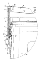
- FIGS. 1 to 3 show a sectional side view of a portion of a cleaning machine on which the locking mechanism is arranged.
- the cleaning machine has a cleaning container 5, which can be closed by a door 4 at its Frontrozmoi loading page.
- the door 4 is pivotally mounted on the cleaning container 5.
- a locking device 10 is arranged on one of the pivot axis of the door 4 opposite end side of the door.
- the locking device 10 is preferably designed as a U-shaped locking pin, wherein the base side of the "U” is parallel to the door front and the base of the "U” opposite opening in the direction of a moving part 1, which is preferably arranged on top of the cleaning container 5 below a cleaning machine lid, not shown.
- the positioning unit 1 has a first drive unit 2, preferably an electric motor, on the drive shaft of which a pinion 13 is mounted, whose teeth engage in a toothed rack 7.
- a control rod 8 is arranged, which is drivable by a second drive unit 6 and along the traverse unit relative to the rack 7 is linearly movable.
- the second drive unit 6 preferably consists of a lifting magnet with a lifting rod 17 to which the control rod 8 is fixed with one end 18 with a nut 19.
- the solenoid Upon activation of the solenoid so the lifting rod 17 is moved in or out of the magnet, so that so that the control rod is moved relative to and parallel to the rack.
- the control rod 8 is disposed between the rack 7 and a counter-rod 16, wherein the counter-rod 16 is connected to the rack 7 in a manner not shown here and is movable with this.
- a Sch Strukturklobenfalle 3 is arranged, which has at least one latching hook 9, of the along the track 1 slidably disposed control rod for locking or releasing the latching hook 9 in at least one of the latching hook corresponding latching point 12 of the locking bolt can be pressed.
- the locking bolt latch 3 has two latching hooks 9, between which the control rod 8 is movable.
- Each of the latching hooks 9 is biased so that it springs away from the respective latching point 12 of the locking bolt 10, as soon as the control rod 8 is pushed back from its position in which it presses the latching hook or 9 in the respective latching point 12 of the locking block 10.
- these are preferably connected by a spring element 11.
- the spring element 11 is preferably formed as a torsion spring.
- a control panel 16 connected to the control unit 16 is preferably provided on the door 4, which has an operating element for controlling this second drive unit.
- This control can be designed as a button or switch.
- the control panel 14 additionally has a further operating element for inputting an unlocking signal.
- Such an operating element may be, for example, a numeric keypad via which the user must enter a numerical code in order to access the loading of the cleaning machine after the subsequent actuation of the door opening button.
- the opening of the door 4 of the cleaning machine takes place such that after a program first by moving the first drive unit 2, the track 1 is pushed in the direction of the locking device 10 while the door 4 is pushed into a first opening position to a drying of To support loading of the cleaning tank.
- the track unit 1 is moved about 10 cm in the direction of the door by motor.
- a user first has to enter an unlocking signal via the control panel 14, for example by entering a numerical code via a numeric keypad of the control panel 14.
Landscapes
- Washing And Drying Of Tableware (AREA)
- Centrifugal Separators (AREA)
- Power-Operated Mechanisms For Wings (AREA)
Abstract
Description
- Die vorliegende Erfindung betrifft einen Reinigungsautomaten nach dem Oberbegriff des Anspruchs 1 sowie ein Verfahren zum Öffnen einer Tür eines Reinigungsautomaten gemäß dem Oberbegriff des Anspruchs 12.
- Die
DE 10 2005 028 449 A1 offenbart einen Geschirrspüler mit einem Spülbehälter, der durch eine schwenkbare Tür verschließbar ist, wobei zum Verschließen eine an der Tür angeordnete Verriegelungseinrichtung in einen am Spülbehälter angeordneten Schließkloben greift. Zum spaltweisen Öffnen der Tür durch eine Gerätesteuerung ist der Schließkloben an einer mittels eines Motors verschließbaren Schließplatte angeordnet, wobei die Schließplatte in eine erste Öffnungsposition mit einer geringen Spaltbreite und in eine zweite Öffnungsposition mit einer großen Spaltbreite fahrbar ist. Durch die Möglichkeit, die Tür automatisch in eine Öffnungsposition zu fahren, bei der diese um einen Spalt von mehreren Zentimetern geöffnet wird, wird die Trocknung nach einem Reinigungsvorgang vorteilhaft unterstützt. - Die Tür eines solchen Geschirrspülers ist als sogenannter Aufreißverschluss ausgebildet, das heißt die Tür ist jederzeit von einem Anwender zu öffnen bzw. zu entriegeln, was bei Reinigungsautomaten wie beispielsweise professionellen Spülmaschinen oder auch Desinfektionsautomaten zu Sicherheitsproblemen führen kann. Insbesondere eine Reinigung bei sehr hohen Temperaturen kann dazu führen, dass auch nach einem mehrere Minuten andauernden Trocknungsvorgang, bei dem die Tür des Reinigungsautomaten bereits um einen Spalt geöffnet ist, die in dem Reinigungsautomat befindlichen Gegenstände noch so heiß sind, dass ein versehentliches Öffnen der Tür vermieden werden muss.
- Aufgabe der vorliegenden Erfindung ist es daher, einen Reinigungsautomaten sowie ein Verfahren zum Öffnen einer Tür eines Reinigungsautomaten zu schaffen, bei dem ein direktes Öffnen der Tür während oder nach einem Reinigungsvorgang verhindert wird.
- Diese Aufgabe wird durch einen Reinigungsautomaten mit den Merkmalen des Anspruchs 1 beziehungsweise ein Verfahren zum Öffnen einer Tür eines Reinigungsautomaten mit den Merkmalen des Anspruchs 12 gelöst.
- Erfindungsgemäß weist der Reinigungsautomat eine Antriebseinheit auf einer Verfahreinheit auf, an der eine Steuerstange derart linear verfahrbar festgelegt ist, dass die Steuerstange zur Ver- oder Entriegelung der Verfahreinheit in eine an einer Tür des Reinigungsautomaten angeordnete Verriegelungseinrichtung ein- oder ausfahrbar ist. Durch diese von der Antriebseinheit angetriebene Steuerstange, welche zur Ver- oder Entriegelung mit der Verfahreinheit wechselwirkt, ist eine von der Türposition unabhängige Ver- und Entriegelung ermöglicht.
- Weitere vorteilhafte Ausgestaltungen und Weiterbildungen der Erfindung sind Gegenstand der Unteransprüche.
- Gemäß einer bevorzugten Ausgestaltung der Erfindung ist die Verriegelungseinrichtung als Schließkloben ausgebildet und die Verfahreinheit weist an ihrem der Verriegelungseinrichtung zugewandten Ende eine Schließklobenfalle mit mindestens einem Rasthaken auf, der von der entlang der Verfahreinheit verschiebbar angeordneten Steuerstange zur Arretierung beziehungsweise Freigabe des Rasthakens in mindestens eine zu dem Rasthaken korrespondierende Raststelle des Schließklobens drückbar ist. Dadurch ist eine einfache und sichere Verriegelung der Verfahreinheit an der Verriegelungseinrichtung ermöglicht, welche separat von der Steuerung der Verfahreinheit steuerbar ist und somit eine von der Position der Verfahreinheit unabhängige Ver- und Entriegelung der Tür ermöglicht.
- Die Erfindung wird nachfolgend anhand eines Ausführungsbeispiels mit Bezug auf die beigefügten Zeichnungen näher erläutert. Es zeigen:
- Figur 1
- eine schematische Seitenschnittansicht des Verschließmechanismus eines erfindungsgemäßen Reinigungsautomaten mit geschlossener und verriegelter Tür,
- Figur 2
- den Verschließmechanismus aus
Figur 1 mit spaltweise geöffneter und verriegelter Tür, - Figur 3
- den Verschließmechanismus mit spaltweise geöffneter und entriegelter Tür und
- Figur 4
- eine schematische Draufsicht auf den Verschließmechanismus des erfindungsgemäß aufgebauten Reinigungsautomaten.
- Die
Figuren 1 bis 3 zeigen eine geschnittene Seitenansicht eines Bereiches eines Reinigungsautomaten, an dem der Schließmechanismus angeordnet ist. Der Reinigungsautomat weist einen Reinigungsbehälter 5 auf, der an seiner Frontbeziehungsweise Beladeseite von einer Tür 4 verschließbar ist. Die Tür 4 ist dazu schwenkbar an dem Reinigungsbehälter 5 angeordnet. Zum Verschließen und Verriegeln der Tür 4 ist an einer der Schwenkachse der Tür 4 gegenüberliegenden Stirnseite der Tür eine Verriegelungseinrichtung 10 angeordnet. Die Verriegelungseinrichtung 10 ist bevorzugt als U-förmiger Schließkloben ausgebildet, wobei die Grundseite des "U" parallel zur Türfront liegt und die der Grundseite des "U" gegenüberliegende Öffnung in Richtung einer Verfahreinheit 1 zeigt, welche bevorzugt oben auf dem Reinigungsbehälter 5 unterhalb eines nicht gezeigten Reinigungsautomatendeckels angeordnet ist. - Die Verfahreinheit 1 weist eine erste Antriebseinheit 2 auf, vorzugsweise einen Elektromotor, auf dessen Antriebswelle ein Ritzel 13 aufgesetzt ist, dessen Zähne in eine Zahnstange 7 eingreifen. Parallel zu der Zahnstange 7 ist eine Steuerstange 8 angeordnet, die von einer zweiten Antriebseinheit 6 antreibbar ist und längs der Verfahreinheit relativ zu der Zahnstange 7 linear verfahrbar ist. Die zweite Antriebseinheit 6 besteht vorzugsweise aus einem Hubmagneten mit einer Hubstange 17, an welcher die Steuerstange 8 mit einem Ende 18 mit einer Mutter 19 festgelegt ist. Bei Aktivierung des Hubmagneten wird so die Hubstange 17 in den Magneten hinein- oder herausgefahren, so dass damit die Steuerstange relativ und parallel zur Zahnstange verfahren wird. Bevorzugt ist die Steuerstange 8 zwischen der Zahnstange 7 und einer Konterstange 16 angeordnet, wobei die Konterstange 16 mit der Zahnstange 7 in hier nicht dargestellter Weise verbunden ist und mit dieser verfahrbar ist.
- An dem der Tür 4 beziehungsweise der Verriegelungseinrichtung 10 zugewandten Ende der Verfahreinheit 1 ist eine Schließklobenfalle 3 angeordnet, welche mindestens einen Rasthaken 9 aufweist, der von der entlang der Verfahreinheit 1 verschiebbar angeordneten Steuerstange zur Arretierung beziehungsweise Freigabe des Rasthaken 9 in mindestens eine zu dem Rasthaken korrespondierende Raststelle 12 des Schließkloben drückbar ist. Bevorzugt weist die Schließklobenfalle 3 zwei Rasthaken 9 auf, zwischen denen die Steuerstange 8 verfahrbar ist.
- Jeder der Rasthaken 9 ist dabei so vorgespannt, dass er von der jeweiligen Raststelle 12 des Schließklobens 10 wegfedert, sobald die Steuerstange 8 aus ihrer Position, in der sie den oder die Rasthaken 9 in die jeweilige Raststelle 12 des Schließklobens 10 drückt, zurückgeschoben ist. Bei der Ausbildung mit mehreren Rasthaken 9 sind diese vorzugsweise durch ein Federelement 11 verbunden. Das Federelement 11 ist dabei bevorzugt als Drehfeder ausgebildet.
- Zur Aktivierung der zweiten Antriebseinheit 6 und damit der Bewegung der Steuerstange 8 ist bevorzugt an der Tür 4 ein mit der Steuereinheit 16 verbundenes Bedienfeld 14 vorgesehen, das ein Bedienelement zur Steuerung dieser zweiten Antriebseinheit aufweist. Dieses Bedienelement kann als Taste oder Schalter ausgebildet sein. In einer bevorzugten Ausbildungsform weist das Bedienfeld 14 zusätzlich ein weiteres Bedienelement zur Eingabe eines Entriegelungssignals auf. Ein solches Bedienelement kann beispielsweise eine Zahlentastatur sein, über die der Anwender einen Zahlencode eingeben muss, um nach dem anschließenden Betätigen der Türöffnungstaste Zugang zur Beladung des Reinigungsautomaten zu bekommen.
- Während des Betriebs erfolgt das Öffnen der Tür 4 des Reinigungsautomaten dergestalt, dass nach einem Programmablauf zunächst durch Ansteuerung der ersten Antriebseinheit 2 die Verfahreinheit 1 in Richtung der Verriegelungseinrichtung 10 geschoben wird und dabei die Tür 4 in eine erste Öffnungsposition geschoben wird, um eine Trocknung der Beladung des Reinigungsbehälters zu unterstützen. Dazu wird die Verfahreinheit 1 etwa 10 cm in Richtung der Tür motorisch verfahren. Um nach dem Trocknungsvorgang die Tür öffnen zu können, muss von einem Anwender zunächst ein Entriegelungssignal über das Bedienfeld 14 eingegeben werden, beispielsweise durch Eingabe eines Zahlencodes über eine Zahlentastatur des Bedienfelds 14. Erst danach bewirkt ein Betätigen einer Türöffnungstaste des Bedienfelds 14 die Aussendung eines Entriegelungssignals an die Steuereinheit 16, welche sodann die zweite Antriebseinheit 6 aktiviert und die Steuerstange 8 in eine Position fährt, bei der der oder die Rasthaken aus den Raststellen 12 des Schließklobens 10 herausfedern. Durch dieses Außereingriffbringen der Verriegelungseinrichtung 10 mit der Verfahreinheit ist die Tür 4 entriegelt, so dass diese vollständig geöffnet werden kann.
Claims (14)
- Reinigungsautomat mit einem Reinigungsbehälter (5), aufweisend- eine an dem Reinigungsbehälter (5) schwenkbar angeordnete Tür (4),- eine von einer Steuereinheit gesteuerte erste Antriebseinheit (2),- eine linear verfahrbar von der ersten Antriebseinheit (2) antreibbare Verfahreinheit (1) zur Positionierung der Tür (4),- eine an der Tür (4) angeordnete Verriegelungseinrichtung (10), die zum Positionieren und Verriegeln der Tür (4) mit der Verfahreinheit (1) in Wirkverbindung steht,dadurch gekennzeichnet,
dass auf der Verfahreinheit (1) eine zweite Antriebseinheit (6) angeordnet ist, an der eine Steuerstange (8) derart linear verfahrbar festgelegt ist, dass die Steuerstange (8) zur Ver- oder Entriegelung der Verfahreinheit (1) in die Verriegelungseinrichtung (10) ein- oder ausfahrbar ist. - Reinigungsautomat nach Anspruch 1,
dadurch gekennzeichnet,
dass die Verriegelungseinrichtung (10) als Schließkloben ausgebildet ist und die Verfahreinheit (1) an ihrem der Verriegelungseinrichtung (10) zugewandten Ende eine Schließklobenfalle (3) aufweist. - Reinigungsautomat nach Anspruch 2,
dadurch gekennzeichnet,
dass die Schließklobenfalle (3) mindestens einen Rasthaken (9) aufweist, der von der entlang der Verfahreinheit (1) verschiebbar angeordneten Steuerstange (8) zur Arretierung bzw. Freigabe des mindestens einen Rasthakens (9) in mindestens eine zu dem Rasthaken (9) korrespondierende Raststelle (12) des Schließkloben (10) drückbar ist. - Reinigungsautomat nach Anspruch 3,
dadurch gekennzeichnet,
dass die Schließklobenfalle (3) zwei Rasthaken (9) aufweist und dass die entlang der Verfahreinheit (1) verschiebbar angeordnete Steuerstange (8) zwischen den Rasthaken (9) angeordnet ist. - Reinigungsautomat nach Anspruch 3 oder 4,
dadurch gekennzeichnet,
dass der mindestens eine Rasthaken (9) so vorgespannt ist, dass er von der jeweiligen Raststelle (12) des Schließkloben (10) weg federt. - Reinigungsautomat nach Anspruch 5,
dadurch gekennzeichnet,
dass zur Vorspannung der Rasthaken (9) die Rasthaken durch ein Federelement (11) verbunden sind. - Reinigungsautomat nach Anspruch 6,
dadurch gekennzeichnet,
dass das Federelement (11) als Drehfeder ausgebildet ist. - Reinigungsautomat nach einem der vorstehenden Ansprüche,
dadurch gekennzeichnet,
dass die Verfahreinheit (1) eine Zahnstange (7) und die erste Antriebseinheit (2) ein mit der Zahnstange (7) im Eingriff stehendes Ritzel (13) aufweist. - Reinigungsautomat nach einem der vorstehenden Ansprüche,
dadurch gekennzeichnet,
dass die zweite Antriebseinheit (6) als Hubmagnet ausgebildet ist. - Reinigungsautomat nach einem der vorstehenden Ansprüche,
dadurch gekennzeichnet,
dass an der Tür (4) ein mit der Steuereinheit (16) verbundenes Bedienfeld (14), aufweisend ein Bedienelement zur Steuerung der zweiten Antriebseinheit (6), angeordnet ist. - Reinigungsautomat nach Anspruch 10,
dadurch gekennzeichnet,
dass das Bedienfeld (14) ein Bedienelement zur Eingabe eines Entriegelungssignals aufweist. - Verfahren zum Öffnen einer Tür (4) eines Reinigungsautomaten gemäß einem oder mehreren der vorstehenden Ansprüche, aufweisend die folgenden Verfahrensschritte:- Bewegen der Tür (4) in eine erste Öffnungsposition durch lineares Verfahren der Verfahreinheit (1) in Richtung der Tür (4), während die an der Tür (4) angeordnete Verriegelungseinrichtung (10) mit der Verfahreinheit (1) im Eingriff steht,gekennzeichnet durch die Verfahrensschritte:- Eingabe eines Entriegelungssignals über das Bedienfeld (14),- Außer Eingriff bringen der Verriegelungseinrichtung (10) mit der Verfahreinheit (1).
- Verfahren nach Anspruch 12,
dadurch gekennzeichnet,
dass zum Entriegeln der Verriegelungseinheit die Steuerstange (8) aus der den mindestens einen Rasthaken (9) in mindestens eine zu dem Rasthaken (9) korrespondierende Raststelle (12) des Schließkloben (10) drückenden Position in eine Position verfahren wird, bei der der oder die Rasthaken (9) von der jeweiligen Raststelle (12) des Schließkloben (10) weg federt bzw. federn. - Verfahren nach Anspruch 13,
dadurch gekennzeichnet,
dass zum Entriegeln der Verriegelungseinheit die zweite Antriebseinheit (6) von der Steuereinheit (16) derart angesteuert wird, dass die zweite Antriebseinheit (6) die Steuerstange (8) aus der den mindestens einen Rasthaken (9) in mindestens eine zu dem Rasthaken (9) korrespondierende Raststelle (12) des Schließkloben (10) drückenden Position in eine Position verfährt, bei der der oder die Rasthaken (9) von der jeweiligen Raststelle (12) des Schließkloben (10) weg federt bzw. federn.
Priority Applications (1)
| Application Number | Priority Date | Filing Date | Title |
|---|---|---|---|
| PL09401038T PL2193740T3 (pl) | 2008-11-19 | 2009-11-16 | Automat do czyszczenia |
Applications Claiming Priority (1)
| Application Number | Priority Date | Filing Date | Title |
|---|---|---|---|
| DE102008058257A DE102008058257B4 (de) | 2008-11-19 | 2008-11-19 | Reinigungsautomat |
Publications (2)
| Publication Number | Publication Date |
|---|---|
| EP2193740A1 true EP2193740A1 (de) | 2010-06-09 |
| EP2193740B1 EP2193740B1 (de) | 2012-04-18 |
Family
ID=41726188
Family Applications (1)
| Application Number | Title | Priority Date | Filing Date |
|---|---|---|---|
| EP09401038A Not-in-force EP2193740B1 (de) | 2008-11-19 | 2009-11-16 | Reinigungsautomat |
Country Status (4)
| Country | Link |
|---|---|
| EP (1) | EP2193740B1 (de) |
| AT (1) | ATE553688T1 (de) |
| DE (1) | DE102008058257B4 (de) |
| PL (1) | PL2193740T3 (de) |
Cited By (15)
| Publication number | Priority date | Publication date | Assignee | Title |
|---|---|---|---|---|
| EP2394558A3 (de) * | 2010-05-12 | 2012-06-13 | Miele & Cie. KG | Spülautomat, insbesondere Haushaltgeschirrspülmaschine, mit einer automatisch zu öffnenden Tür |
| WO2013098245A1 (en) * | 2011-12-30 | 2013-07-04 | Arcelik Anonim Sirketi | Dishwasher comprising an automatic door opening mechanism |
| ITTO20120124A1 (it) * | 2012-02-13 | 2013-08-14 | Elbi Int Spa | Dispositivo per la chiusura di una porta di un apparecchio elettrodomestico, in particolare per una macchina lavatrice, quale una macchina lavastoviglie. |
| WO2016199056A1 (en) * | 2015-06-10 | 2016-12-15 | Elbi International S.P.A. | System to control the closing of a door of a household appliance, in particular for a washing machine, such as a dishwasher |
| EP3444531A1 (de) * | 2017-08-14 | 2019-02-20 | Electrolux Appliances Aktiebolag | Türöffnungssystem für ein küchengerät |
| WO2020187360A1 (de) * | 2019-03-21 | 2020-09-24 | Kiekert Ag | Aufstellvorrichtung für ein kraftfahrzeugtürelement |
| CN111789556A (zh) * | 2019-04-08 | 2020-10-20 | 华帝股份有限公司 | 内腔体自动进出机构及其餐具收集清洁装置 |
| WO2020228894A1 (de) * | 2019-05-13 | 2020-11-19 | Kiekert Ag | Aufstellvorrichtung für ein kraftfahrzeugtürelement |
| US20210222464A1 (en) * | 2016-12-23 | 2021-07-22 | Magna Closures Inc. | Power door presenter with latching feature |
| CN114687162A (zh) * | 2020-12-31 | 2022-07-01 | 无锡小天鹅电器有限公司 | 衣物处理设备的门组件及具有其的衣物处理设备 |
| CN114687165A (zh) * | 2020-12-31 | 2022-07-01 | 无锡小天鹅电器有限公司 | 衣物处理设备的门组件及具有其的衣物处理设备 |
| CN114687163A (zh) * | 2020-12-31 | 2022-07-01 | 无锡小天鹅电器有限公司 | 衣物处理设备的门铰链及具有其的衣物处理设备 |
| EP2845532B1 (de) * | 2013-09-04 | 2023-04-26 | Miele & Cie. KG | Haushaltgerät mit automatischem Türöffnungsmechanismus |
| IT202300008742A1 (it) * | 2023-05-03 | 2024-11-03 | Elettrotecnica Rold Srl | Dispositivo ad ingombro ridotto per l’apertura dello sportello di un elettrodomestico |
| LU103460B1 (de) * | 2024-11-21 | 2026-05-22 | Miele & Cie | Haushaltsgerät, insbesondere Geschirrspülmaschine |
Families Citing this family (11)
| Publication number | Priority date | Publication date | Assignee | Title |
|---|---|---|---|---|
| EP2436864B1 (de) * | 2011-10-26 | 2016-09-28 | V-Zug AG | Automatischer Türverschluss für ein Haushaltsgerät |
| KR102034091B1 (ko) * | 2013-10-18 | 2019-11-08 | 삼성전자주식회사 | 식기 세척기 |
| DE202014010390U1 (de) * | 2014-06-04 | 2015-06-30 | Meiko Maschinenbau Gmbh & Co. Kg | Vorrichtung zum Verschließen eines Behandlungsraums einer Geschirrspülmaschine |
| CN108661445B (zh) * | 2017-03-29 | 2021-04-13 | 青岛海尔洗碗机有限公司 | 一种洗碗机自动门锁装置及洗碗机 |
| DE102017211069A1 (de) * | 2017-06-29 | 2019-01-03 | BSH Hausgeräte GmbH | Wäschepflegegerät mit einer Öffnungsvorrichtung |
| DE102017213673B4 (de) | 2017-08-07 | 2022-08-04 | BSH Hausgeräte GmbH | Wäschepflegegerät mit einer Türvorrichtung |
| CN109576959A (zh) * | 2017-09-28 | 2019-04-05 | 博西华电器(江苏)有限公司 | 衣物护理机 |
| CN110016786B (zh) * | 2018-01-08 | 2024-05-07 | 青岛海尔洗涤电器有限公司 | 一种抽屉可自动开合的复式洗衣机 |
| CN110259317B (zh) * | 2019-06-21 | 2024-01-26 | 宁波安佳卫厨电器有限公司 | 一种带自动开门装置的洗碗机 |
| DE102021108809B4 (de) * | 2020-05-08 | 2022-12-15 | Emz-Hanauer Gmbh & Co. Kgaa | Elektrisches Haushaltsgerät |
| IT202400008905A1 (it) * | 2024-04-18 | 2025-10-18 | Elbi Int Spa | Dispositivo di apertura automatica |
Citations (2)
| Publication number | Priority date | Publication date | Assignee | Title |
|---|---|---|---|---|
| US5675934A (en) * | 1994-06-16 | 1997-10-14 | Hong Il Lee | Device capable of opening/closing a door at either side thereof |
| DE102005028449A1 (de) * | 2005-06-17 | 2006-12-21 | Miele & Cie. Kg | Geschirrspülmaschine mit einem Spülbehälter, der durch eine Tür verschließbar ist, und Verfahren zur Durchführung eines Spülprogramms in einer solchen Geschirrspülmaschine |
Family Cites Families (1)
| Publication number | Priority date | Publication date | Assignee | Title |
|---|---|---|---|---|
| DE3922754A1 (de) * | 1989-07-11 | 1991-01-17 | Licentia Gmbh | Geschirrspuelmaschine mit einer vorrichtung fuer definiertes oeffnen der tuer |
-
2008
- 2008-11-19 DE DE102008058257A patent/DE102008058257B4/de not_active Expired - Fee Related
-
2009
- 2009-11-16 PL PL09401038T patent/PL2193740T3/pl unknown
- 2009-11-16 AT AT09401038T patent/ATE553688T1/de active
- 2009-11-16 EP EP09401038A patent/EP2193740B1/de not_active Not-in-force
Patent Citations (2)
| Publication number | Priority date | Publication date | Assignee | Title |
|---|---|---|---|---|
| US5675934A (en) * | 1994-06-16 | 1997-10-14 | Hong Il Lee | Device capable of opening/closing a door at either side thereof |
| DE102005028449A1 (de) * | 2005-06-17 | 2006-12-21 | Miele & Cie. Kg | Geschirrspülmaschine mit einem Spülbehälter, der durch eine Tür verschließbar ist, und Verfahren zur Durchführung eines Spülprogramms in einer solchen Geschirrspülmaschine |
Cited By (24)
| Publication number | Priority date | Publication date | Assignee | Title |
|---|---|---|---|---|
| EP2394558A3 (de) * | 2010-05-12 | 2012-06-13 | Miele & Cie. KG | Spülautomat, insbesondere Haushaltgeschirrspülmaschine, mit einer automatisch zu öffnenden Tür |
| US9474433B2 (en) | 2011-12-30 | 2016-10-25 | Arcelik Anonim Sirketi | Dishwasher comprising an automatic door opening mechanism |
| WO2013098245A1 (en) * | 2011-12-30 | 2013-07-04 | Arcelik Anonim Sirketi | Dishwasher comprising an automatic door opening mechanism |
| US9580952B2 (en) | 2012-02-13 | 2017-02-28 | Elbi International S.P.A. | Device for closing the door of a household appliance, in particular for a washing machine, such as a dishwasher |
| WO2013121318A1 (en) * | 2012-02-13 | 2013-08-22 | Elbi International S.P.A. | Device for closing the door of a household appliance, in particular for a washing machine, such as a dishwasher |
| ITTO20120124A1 (it) * | 2012-02-13 | 2013-08-14 | Elbi Int Spa | Dispositivo per la chiusura di una porta di un apparecchio elettrodomestico, in particolare per una macchina lavatrice, quale una macchina lavastoviglie. |
| EP2845532B1 (de) * | 2013-09-04 | 2023-04-26 | Miele & Cie. KG | Haushaltgerät mit automatischem Türöffnungsmechanismus |
| WO2016199056A1 (en) * | 2015-06-10 | 2016-12-15 | Elbi International S.P.A. | System to control the closing of a door of a household appliance, in particular for a washing machine, such as a dishwasher |
| US20210222464A1 (en) * | 2016-12-23 | 2021-07-22 | Magna Closures Inc. | Power door presenter with latching feature |
| EP3444531A1 (de) * | 2017-08-14 | 2019-02-20 | Electrolux Appliances Aktiebolag | Türöffnungssystem für ein küchengerät |
| WO2020187360A1 (de) * | 2019-03-21 | 2020-09-24 | Kiekert Ag | Aufstellvorrichtung für ein kraftfahrzeugtürelement |
| US11821254B2 (en) | 2019-03-21 | 2023-11-21 | Kiekert Ag | Door presenting device for a motor vehicle door element |
| CN111789556A (zh) * | 2019-04-08 | 2020-10-20 | 华帝股份有限公司 | 内腔体自动进出机构及其餐具收集清洁装置 |
| WO2020228894A1 (de) * | 2019-05-13 | 2020-11-19 | Kiekert Ag | Aufstellvorrichtung für ein kraftfahrzeugtürelement |
| CN114687162A (zh) * | 2020-12-31 | 2022-07-01 | 无锡小天鹅电器有限公司 | 衣物处理设备的门组件及具有其的衣物处理设备 |
| CN114687163A (zh) * | 2020-12-31 | 2022-07-01 | 无锡小天鹅电器有限公司 | 衣物处理设备的门铰链及具有其的衣物处理设备 |
| CN114687163B (zh) * | 2020-12-31 | 2023-11-03 | 无锡小天鹅电器有限公司 | 衣物处理设备的门铰链及具有其的衣物处理设备 |
| CN114687162B (zh) * | 2020-12-31 | 2023-11-03 | 无锡小天鹅电器有限公司 | 衣物处理设备的门组件及具有其的衣物处理设备 |
| CN114687165B (zh) * | 2020-12-31 | 2023-11-03 | 无锡小天鹅电器有限公司 | 衣物处理设备的门组件及具有其的衣物处理设备 |
| CN114687165A (zh) * | 2020-12-31 | 2022-07-01 | 无锡小天鹅电器有限公司 | 衣物处理设备的门组件及具有其的衣物处理设备 |
| IT202300008742A1 (it) * | 2023-05-03 | 2024-11-03 | Elettrotecnica Rold Srl | Dispositivo ad ingombro ridotto per l’apertura dello sportello di un elettrodomestico |
| WO2024228108A1 (en) * | 2023-05-03 | 2024-11-07 | Elettrotecnica Rold S.R.L. | Compact device for opening the door of a household appliance |
| LU103460B1 (de) * | 2024-11-21 | 2026-05-22 | Miele & Cie | Haushaltsgerät, insbesondere Geschirrspülmaschine |
| WO2026109348A1 (de) * | 2024-11-21 | 2026-05-28 | Miele & Cie. Kg | Haushaltsgerät, insbesondere geschirrspülmaschine |
Also Published As
| Publication number | Publication date |
|---|---|
| ATE553688T1 (de) | 2012-05-15 |
| DE102008058257A1 (de) | 2010-06-02 |
| EP2193740B1 (de) | 2012-04-18 |
| PL2193740T3 (pl) | 2012-08-31 |
| DE102008058257B4 (de) | 2010-07-15 |
Similar Documents
| Publication | Publication Date | Title |
|---|---|---|
| EP2193740B1 (de) | Reinigungsautomat | |
| EP2280632B1 (de) | Geschirrspülmaschine mit einer vorrichtung zum spaltweisen öffnen der tür | |
| DE4224909C2 (de) | Treibstangenbeschlag für Türen, Fenster oder dgl. mit elektrischer Sperrvorrichtung | |
| EP3336292B1 (de) | Verfahren zum betätigen eines türschlosses und türschloss | |
| EP2358962B1 (de) | Möbelscharnier mit rotationsdämpfer | |
| DE102008011551B4 (de) | Selbstverriegelnde Zusatzverriegelung | |
| EP3951123A1 (de) | Türgriffanordnung für ein kraftfahrzeug | |
| DE4015522A1 (de) | Vorrichtung zum sperren und entsperren von geschlossenen tueren zum innenraum eines kraftfahrzeuges | |
| EP2845532A1 (de) | Haushaltgerät mit automatischem Türöffnungsmechanismus | |
| DE102021128868A1 (de) | Kraftfahrzeug-Schloss insbesondere Kraftfahrzeug-Türschloss | |
| EP2497854B1 (de) | Verriegelungsanordnung zum verriegeln einer tür eines haushaltsgeräts sowie haushaltsgerät | |
| EP0687439A1 (de) | Geschirrspülmaschine | |
| DE3031066A1 (de) | Zentralgesteuerte verschlusseinrichtung fuer kraftfahrzeugtueren | |
| DE4125448C2 (de) | Elektromotorischer Stellantrieb für eine zentrale Türverriegelungsanlage eines Kraftfahrzeugs | |
| EP3458660B1 (de) | Türschliessmechanismus mit einer im türrahmen eingelassenen aufnahme für den schliessriegel einer in die tür eingelassenen vorrichtung zum steuern des schliessriegels in die öffnungsstellung mittels eines manuell steuerbaren betätigungsglieds | |
| DE102022124424A1 (de) | Drück-Drück-Türverschluss und hiermit ausgestattetes elektrisches Haushaltsgerät | |
| DE19848275C2 (de) | Vorrichtung zum Verriegeln einer Tür eines Haushaltsgerätes | |
| DE202009012289U1 (de) | Elektronisches Verschlusssystem für Schränke mit einer im Schrankinneren angeordneten elektromotorisch gesteuerten Verriegelungsmechanik | |
| EP4474565B1 (de) | Mechanismus für eine tür eines elektrischen haushaltsgeräts | |
| EP1460163B1 (de) | Türverriegelung für elektrische Geräte, insbesondere für Waschmaschinen | |
| EP2256273A2 (de) | Treibstangenschloss mit Mehrfachverriegelung | |
| WO2024153279A1 (de) | Schloss, insbesondere heckklappenschloss, für ein kraftfahrzeug | |
| EP1614840A2 (de) | Vorrichtung zum Zuziehen einer geöffneten Klappe oder Tür eines Fahrzeugs an die Karosserie | |
| DE19628149B4 (de) | Einrichtung an einem Kraftfahrzeug mit Heckklappe | |
| DE19908191C1 (de) | Automatische Flügel- oder Türanlage |
Legal Events
| Date | Code | Title | Description |
|---|---|---|---|
| PUAI | Public reference made under article 153(3) epc to a published international application that has entered the european phase |
Free format text: ORIGINAL CODE: 0009012 |
|
| AK | Designated contracting states |
Kind code of ref document: A1 Designated state(s): AT BE BG CH CY CZ DE DK EE ES FI FR GB GR HR HU IE IS IT LI LT LU LV MC MK MT NL NO PL PT RO SE SI SK SM TR |
|
| AX | Request for extension of the european patent |
Extension state: AL BA RS |
|
| 17P | Request for examination filed |
Effective date: 20100511 |
|
| RIC1 | Information provided on ipc code assigned before grant |
Ipc: A47L 15/42 20060101AFI20101027BHEP |
|
| GRAP | Despatch of communication of intention to grant a patent |
Free format text: ORIGINAL CODE: EPIDOSNIGR1 |
|
| GRAS | Grant fee paid |
Free format text: ORIGINAL CODE: EPIDOSNIGR3 |
|
| GRAA | (expected) grant |
Free format text: ORIGINAL CODE: 0009210 |
|
| AK | Designated contracting states |
Kind code of ref document: B1 Designated state(s): AT BE BG CH CY CZ DE DK EE ES FI FR GB GR HR HU IE IS IT LI LT LU LV MC MK MT NL NO PL PT RO SE SI SK SM TR |
|
| REG | Reference to a national code |
Ref country code: GB Ref legal event code: FG4D Free format text: NOT ENGLISH |
|
| REG | Reference to a national code |
Ref country code: CH Ref legal event code: EP |
|
| REG | Reference to a national code |
Ref country code: IE Ref legal event code: FG4D Free format text: LANGUAGE OF EP DOCUMENT: GERMAN |
|
| REG | Reference to a national code |
Ref country code: AT Ref legal event code: REF Ref document number: 553688 Country of ref document: AT Kind code of ref document: T Effective date: 20120515 |
|
| REG | Reference to a national code |
Ref country code: GB Ref legal event code: 746 Effective date: 20120508 |
|
| REG | Reference to a national code |
Ref country code: CH Ref legal event code: NV Representative=s name: KATZAROV S.A. |
|
| REG | Reference to a national code |
Ref country code: DE Ref legal event code: R096 Ref document number: 502009003306 Country of ref document: DE Effective date: 20120614 |
|
| REG | Reference to a national code |
Ref country code: NL Ref legal event code: VDEP Effective date: 20120418 |
|
| REG | Reference to a national code |
Ref country code: PL Ref legal event code: LICE Effective date: 20120531 Ref country code: PL Ref legal event code: T3 |
|
| LTIE | Lt: invalidation of european patent or patent extension |
Effective date: 20120418 |
|
| REG | Reference to a national code |
Ref country code: DE Ref legal event code: R084 Ref document number: 502009003306 Country of ref document: DE Effective date: 20120811 |
|
| PG25 | Lapsed in a contracting state [announced via postgrant information from national office to epo] |
Ref country code: IS Free format text: LAPSE BECAUSE OF FAILURE TO SUBMIT A TRANSLATION OF THE DESCRIPTION OR TO PAY THE FEE WITHIN THE PRESCRIBED TIME-LIMIT Effective date: 20120818 Ref country code: FI Free format text: LAPSE BECAUSE OF FAILURE TO SUBMIT A TRANSLATION OF THE DESCRIPTION OR TO PAY THE FEE WITHIN THE PRESCRIBED TIME-LIMIT Effective date: 20120418 Ref country code: CY Free format text: LAPSE BECAUSE OF FAILURE TO SUBMIT A TRANSLATION OF THE DESCRIPTION OR TO PAY THE FEE WITHIN THE PRESCRIBED TIME-LIMIT Effective date: 20120418 Ref country code: SE Free format text: LAPSE BECAUSE OF FAILURE TO SUBMIT A TRANSLATION OF THE DESCRIPTION OR TO PAY THE FEE WITHIN THE PRESCRIBED TIME-LIMIT Effective date: 20120418 Ref country code: NO Free format text: LAPSE BECAUSE OF FAILURE TO SUBMIT A TRANSLATION OF THE DESCRIPTION OR TO PAY THE FEE WITHIN THE PRESCRIBED TIME-LIMIT Effective date: 20120718 Ref country code: LT Free format text: LAPSE BECAUSE OF FAILURE TO SUBMIT A TRANSLATION OF THE DESCRIPTION OR TO PAY THE FEE WITHIN THE PRESCRIBED TIME-LIMIT Effective date: 20120418 |
|
| PG25 | Lapsed in a contracting state [announced via postgrant information from national office to epo] |
Ref country code: SI Free format text: LAPSE BECAUSE OF FAILURE TO SUBMIT A TRANSLATION OF THE DESCRIPTION OR TO PAY THE FEE WITHIN THE PRESCRIBED TIME-LIMIT Effective date: 20120418 Ref country code: PT Free format text: LAPSE BECAUSE OF FAILURE TO SUBMIT A TRANSLATION OF THE DESCRIPTION OR TO PAY THE FEE WITHIN THE PRESCRIBED TIME-LIMIT Effective date: 20120820 Ref country code: LV Free format text: LAPSE BECAUSE OF FAILURE TO SUBMIT A TRANSLATION OF THE DESCRIPTION OR TO PAY THE FEE WITHIN THE PRESCRIBED TIME-LIMIT Effective date: 20120418 Ref country code: HR Free format text: LAPSE BECAUSE OF FAILURE TO SUBMIT A TRANSLATION OF THE DESCRIPTION OR TO PAY THE FEE WITHIN THE PRESCRIBED TIME-LIMIT Effective date: 20120418 Ref country code: GR Free format text: LAPSE BECAUSE OF FAILURE TO SUBMIT A TRANSLATION OF THE DESCRIPTION OR TO PAY THE FEE WITHIN THE PRESCRIBED TIME-LIMIT Effective date: 20120719 |
|
| PG25 | Lapsed in a contracting state [announced via postgrant information from national office to epo] |
Ref country code: EE Free format text: LAPSE BECAUSE OF FAILURE TO SUBMIT A TRANSLATION OF THE DESCRIPTION OR TO PAY THE FEE WITHIN THE PRESCRIBED TIME-LIMIT Effective date: 20120418 Ref country code: RO Free format text: LAPSE BECAUSE OF FAILURE TO SUBMIT A TRANSLATION OF THE DESCRIPTION OR TO PAY THE FEE WITHIN THE PRESCRIBED TIME-LIMIT Effective date: 20120418 Ref country code: CZ Free format text: LAPSE BECAUSE OF FAILURE TO SUBMIT A TRANSLATION OF THE DESCRIPTION OR TO PAY THE FEE WITHIN THE PRESCRIBED TIME-LIMIT Effective date: 20120418 Ref country code: DK Free format text: LAPSE BECAUSE OF FAILURE TO SUBMIT A TRANSLATION OF THE DESCRIPTION OR TO PAY THE FEE WITHIN THE PRESCRIBED TIME-LIMIT Effective date: 20120418 Ref country code: SK Free format text: LAPSE BECAUSE OF FAILURE TO SUBMIT A TRANSLATION OF THE DESCRIPTION OR TO PAY THE FEE WITHIN THE PRESCRIBED TIME-LIMIT Effective date: 20120418 Ref country code: NL Free format text: LAPSE BECAUSE OF FAILURE TO SUBMIT A TRANSLATION OF THE DESCRIPTION OR TO PAY THE FEE WITHIN THE PRESCRIBED TIME-LIMIT Effective date: 20120418 |
|
| PLBE | No opposition filed within time limit |
Free format text: ORIGINAL CODE: 0009261 |
|
| STAA | Information on the status of an ep patent application or granted ep patent |
Free format text: STATUS: NO OPPOSITION FILED WITHIN TIME LIMIT |
|
| 26N | No opposition filed |
Effective date: 20130121 |
|
| PG25 | Lapsed in a contracting state [announced via postgrant information from national office to epo] |
Ref country code: ES Free format text: LAPSE BECAUSE OF FAILURE TO SUBMIT A TRANSLATION OF THE DESCRIPTION OR TO PAY THE FEE WITHIN THE PRESCRIBED TIME-LIMIT Effective date: 20120729 |
|
| REG | Reference to a national code |
Ref country code: DE Ref legal event code: R097 Ref document number: 502009003306 Country of ref document: DE Effective date: 20130121 |
|
| BERE | Be: lapsed |
Owner name: MIELE & CIE. K.G. Effective date: 20121130 |
|
| PG25 | Lapsed in a contracting state [announced via postgrant information from national office to epo] |
Ref country code: BG Free format text: LAPSE BECAUSE OF FAILURE TO SUBMIT A TRANSLATION OF THE DESCRIPTION OR TO PAY THE FEE WITHIN THE PRESCRIBED TIME-LIMIT Effective date: 20120718 |
|
| REG | Reference to a national code |
Ref country code: IE Ref legal event code: MM4A |
|
| PG25 | Lapsed in a contracting state [announced via postgrant information from national office to epo] |
Ref country code: BE Free format text: LAPSE BECAUSE OF NON-PAYMENT OF DUE FEES Effective date: 20121130 |
|
| PG25 | Lapsed in a contracting state [announced via postgrant information from national office to epo] |
Ref country code: IE Free format text: LAPSE BECAUSE OF NON-PAYMENT OF DUE FEES Effective date: 20121116 |
|
| PG25 | Lapsed in a contracting state [announced via postgrant information from national office to epo] |
Ref country code: MT Free format text: LAPSE BECAUSE OF FAILURE TO SUBMIT A TRANSLATION OF THE DESCRIPTION OR TO PAY THE FEE WITHIN THE PRESCRIBED TIME-LIMIT Effective date: 20120418 |
|
| PGFP | Annual fee paid to national office [announced via postgrant information from national office to epo] |
Ref country code: CH Payment date: 20131122 Year of fee payment: 5 Ref country code: GB Payment date: 20131122 Year of fee payment: 5 Ref country code: FR Payment date: 20131119 Year of fee payment: 5 |
|
| PGFP | Annual fee paid to national office [announced via postgrant information from national office to epo] |
Ref country code: IT Payment date: 20131126 Year of fee payment: 5 |
|
| PG25 | Lapsed in a contracting state [announced via postgrant information from national office to epo] |
Ref country code: MC Free format text: LAPSE BECAUSE OF NON-PAYMENT OF DUE FEES Effective date: 20121130 Ref country code: TR Free format text: LAPSE BECAUSE OF FAILURE TO SUBMIT A TRANSLATION OF THE DESCRIPTION OR TO PAY THE FEE WITHIN THE PRESCRIBED TIME-LIMIT Effective date: 20120418 |
|
| PG25 | Lapsed in a contracting state [announced via postgrant information from national office to epo] |
Ref country code: LU Free format text: LAPSE BECAUSE OF NON-PAYMENT OF DUE FEES Effective date: 20121116 Ref country code: SM Free format text: LAPSE BECAUSE OF FAILURE TO SUBMIT A TRANSLATION OF THE DESCRIPTION OR TO PAY THE FEE WITHIN THE PRESCRIBED TIME-LIMIT Effective date: 20120418 |
|
| PG25 | Lapsed in a contracting state [announced via postgrant information from national office to epo] |
Ref country code: HU Free format text: LAPSE BECAUSE OF FAILURE TO SUBMIT A TRANSLATION OF THE DESCRIPTION OR TO PAY THE FEE WITHIN THE PRESCRIBED TIME-LIMIT Effective date: 20091116 |
|
| PGFP | Annual fee paid to national office [announced via postgrant information from national office to epo] |
Ref country code: DE Payment date: 20141130 Year of fee payment: 6 |
|
| PGFP | Annual fee paid to national office [announced via postgrant information from national office to epo] |
Ref country code: PL Payment date: 20141107 Year of fee payment: 6 |
|
| REG | Reference to a national code |
Ref country code: CH Ref legal event code: PL |
|
| GBPC | Gb: european patent ceased through non-payment of renewal fee |
Effective date: 20141116 |
|
| PG25 | Lapsed in a contracting state [announced via postgrant information from national office to epo] |
Ref country code: CH Free format text: LAPSE BECAUSE OF NON-PAYMENT OF DUE FEES Effective date: 20141130 Ref country code: MK Free format text: LAPSE BECAUSE OF FAILURE TO SUBMIT A TRANSLATION OF THE DESCRIPTION OR TO PAY THE FEE WITHIN THE PRESCRIBED TIME-LIMIT Effective date: 20120418 Ref country code: LI Free format text: LAPSE BECAUSE OF NON-PAYMENT OF DUE FEES Effective date: 20141130 |
|
| REG | Reference to a national code |
Ref country code: FR Ref legal event code: ST Effective date: 20150731 |
|
| PG25 | Lapsed in a contracting state [announced via postgrant information from national office to epo] |
Ref country code: GB Free format text: LAPSE BECAUSE OF NON-PAYMENT OF DUE FEES Effective date: 20141116 |
|
| PG25 | Lapsed in a contracting state [announced via postgrant information from national office to epo] |
Ref country code: FR Free format text: LAPSE BECAUSE OF NON-PAYMENT OF DUE FEES Effective date: 20141201 |
|
| PG25 | Lapsed in a contracting state [announced via postgrant information from national office to epo] |
Ref country code: IT Free format text: LAPSE BECAUSE OF NON-PAYMENT OF DUE FEES Effective date: 20141116 |
|
| REG | Reference to a national code |
Ref country code: AT Ref legal event code: MM01 Ref document number: 553688 Country of ref document: AT Kind code of ref document: T Effective date: 20141116 |
|
| PG25 | Lapsed in a contracting state [announced via postgrant information from national office to epo] |
Ref country code: AT Free format text: LAPSE BECAUSE OF NON-PAYMENT OF DUE FEES Effective date: 20141116 |
|
| REG | Reference to a national code |
Ref country code: DE Ref legal event code: R119 Ref document number: 502009003306 Country of ref document: DE |
|
| PG25 | Lapsed in a contracting state [announced via postgrant information from national office to epo] |
Ref country code: DE Free format text: LAPSE BECAUSE OF NON-PAYMENT OF DUE FEES Effective date: 20160601 |
|
| PG25 | Lapsed in a contracting state [announced via postgrant information from national office to epo] |
Ref country code: PL Free format text: LAPSE BECAUSE OF NON-PAYMENT OF DUE FEES Effective date: 20151116 |