EP2185458B1 - Dispositif pour entraîner une porte d'un ascenseur - Google Patents
Dispositif pour entraîner une porte d'un ascenseur Download PDFInfo
- Publication number
- EP2185458B1 EP2185458B1 EP08828623A EP08828623A EP2185458B1 EP 2185458 B1 EP2185458 B1 EP 2185458B1 EP 08828623 A EP08828623 A EP 08828623A EP 08828623 A EP08828623 A EP 08828623A EP 2185458 B1 EP2185458 B1 EP 2185458B1
- Authority
- EP
- European Patent Office
- Prior art keywords
- door
- driving
- vertical portion
- rotating shaft
- motor
- Prior art date
- Legal status (The legal status is an assumption and is not a legal conclusion. Google has not performed a legal analysis and makes no representation as to the accuracy of the status listed.)
- Active
Links
- 229910052751 metal Inorganic materials 0.000 description 4
- 239000002184 metal Substances 0.000 description 4
- 238000012986 modification Methods 0.000 description 3
- 230000004048 modification Effects 0.000 description 3
- 229920000642 polymer Polymers 0.000 description 3
- 239000000463 material Substances 0.000 description 2
- 239000012858 resilient material Substances 0.000 description 2
- 229910045601 alloy Inorganic materials 0.000 description 1
- 239000000956 alloy Substances 0.000 description 1
- 239000000428 dust Substances 0.000 description 1
- 150000002739 metals Chemical class 0.000 description 1
- 239000002245 particle Substances 0.000 description 1
- XLYOFNOQVPJJNP-UHFFFAOYSA-N water Substances O XLYOFNOQVPJJNP-UHFFFAOYSA-N 0.000 description 1
- 238000004804 winding Methods 0.000 description 1
Images


Classifications
-
- B—PERFORMING OPERATIONS; TRANSPORTING
- B66—HOISTING; LIFTING; HAULING
- B66B—ELEVATORS; ESCALATORS OR MOVING WALKWAYS
- B66B13/00—Doors, gates, or other apparatus controlling access to, or exit from, cages or lift well landings
- B66B13/02—Door or gate operation
- B66B13/06—Door or gate operation of sliding doors
- B66B13/08—Door or gate operation of sliding doors guided for horizontal movement
-
- B—PERFORMING OPERATIONS; TRANSPORTING
- B66—HOISTING; LIFTING; HAULING
- B66B—ELEVATORS; ESCALATORS OR MOVING WALKWAYS
- B66B13/00—Doors, gates, or other apparatus controlling access to, or exit from, cages or lift well landings
- B66B13/02—Door or gate operation
- B66B13/06—Door or gate operation of sliding doors
Definitions
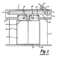
- Fig. 1 is a front elevation view illustrating a conventional elevator car
- Fig. 2 is a side view showing the car door apparatus in Fig. 1 , with car body 1 being shown in cross-section.
- elevator car entrance 2 is provided at the front face of car body 1.
- Door frame 3 extends along the width of entrance 2, and is fixed to car body 1 above entrance 2.
- Door motor 4 having motor pulley 5 is mounted on door frame 3.
- Reduction pulley 6 having a larger diameter than motor pulley 5 has belt 7 wound between motor pulley 5 and reduction pulley 6.
- Drive pulley 8 has a smaller diameter than and is coaxial with reduction pulley 6, can be rotated integrally with the reduction pulley 6.
- Following pulley 9 is provided at the door frame 3, with second belt 10 wound between drive pulley 8 and following pulley 9.
- Door rail 11 extends along the width direction of entrance 2 and is attached to door frame 3.
- Two car doors 12 are suspended from door rail 11 through door hangers 13.
- Each door hanger 13 has two rollers 14 which are rotated along door rail 11.
- Car doors 12 are connected to second belt 10 through door hanger 13 and belt holders 15 and 16.
- a plurality of door shoes 17 are attached adjacent the lower edge of each of doors 12.
- Door shoes 17 are inserted into a groove (not shown) of sill 18 disposed at the lower portion of entrance 2.
- car body 1 is provided with upper panel 19 and ceiling panel 20.
- motor pulley 5 is rotated by door motor 4, and the rotation is transmitted to reduction pulley 6 through reduction belt 7.
- Drive pulley 8 is rotated with reduction pulley 6, and thus second belt 10 is circulated and following pulley 9 is rotated.
- door hangers 13 are connected to belt 10, door hangers 13 and doors 12 are reciprocated along door rail 11 by the circulation of second belt 10 to open or close entrance 2. Doors 12 are suspended from door rail 11 and the bottom portions of doors 12 are guided by the sill groove of sill 18 during the opening and the closing of doors 12.
- Figs. 1 and 2 show a prior art device for driving a door of an elevator car, wherein door motor 4 is located above car body 1 and ceiling plate 20 of car body 1 is placed just below door motor 4.
- ceiling plate 20 cannot help but interfere with door motor 4. Accordingly, the door driving device must be redesigned in order to avoid such interference. Further, large noise may occur in such a door driving device due to reduction pulley 6 and reduction belt 7 during the movement of doors 12.
- Figs. 3 and 4 show another prior art device for driving doors 2 of elevator car 1, wherein door motor 22 is disposed under horizontal portion 21 b of a door frame 21 inside plane A extending parallel to vertical end face 18b of a sill, thereby eliminating interference between door motor 22 and ceiling plate 20.
- bolts 23 hold door motor 22 in place on horizontal portion 21b of door frame 21, while vertical portion 21a extends down to attach to rail 11.
- Driving pulley 24 is attached to drive motor 22, and connected to following pulley 25 via belt 26.
- Rail 11 extends along the width of car 1, with door hangers 13 and corresponding rollers 14 being supported thereon.
- Doors 12 are connected to belt 26 through door hangers 13 and belt holders 15 and 16.
- Door shoes 17 are attached adjacent lower edge of doors 12, and are inserted into groove 18a of sill 18. The door operates as described before, with the exception being that drive motor is connected directly to driving pulley 24 without a reduction mechanism.
- a driving motor which is configured to cause less vibration and noise, is necessary for driving a door of an elevator. Further, a device for driving a door of an elevator that does not interfere with a ceiling plate of an elevator and is compactly configured is needed.
- the present invention aims to resolve one or more of the aforementioned issues that afflict elevator systems.
- a device for driving elevator doors and having the features of the preamble of claim 1 is disclosed in JP 2007-153495 A1 .
- a further device for driving elevator doors is disclosed in JP 2004-1982 A1 .
- the present invention provides a device for driving a door of an elevator, which device is as set forth in claim 1.
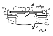
- FIG. 5 is a front elevation view of a portion of an embodiment of an elevator car.
- FIG. 6 is a cross-sectional view of a portion of the car shown in FIG. 5 .
- Illustrated in FIGS. 5 and 6 are elevator door driving device 100, elevator car 110, frame 112, doorway 114, ceiling plate 116, doors 121 and 122, door hangers 123 and 124 having upper portions 123a and 124a and belt holders 123b and 124b, upper roller 125b, lower roller 126b, door header 130 with vertical portion 130a, horizontal portion 130b, and bent section 130c, rail 132, driving motor 140, driven pulley 152, and belt 154 having lower portion 154a and upper portion 154b.
- elevator door driving device 100 is configured to be disposed at elevator car 110 to drive doors 121 and 122.
- Elevator door driving device 100 has door header 130 mounted above doorway 114 of elevator car 110; door rail 132 provided on door header 130 for supporting upper sides of doors 121 and 122; driving motor 140 disposed on door header 130 above door rail 132 and having driving pulley (not shown) therein; driven (or following or idler) pulley 152 rotatably provided on door header 130 as being apart from driving pulley; and drive belt 154 wound around driving pulley and driven pulley 152 along a lengthwise direction of door header 130.
- Drive belt 154 is a continuous piece of material, such as a rubber strap or rope.
- Doors 121 and 122 each contain door hanger 123 and 124, respectively, which attach doors 121 and 122 to drive belt 154.
- Upper portion 123a of door hanger 123 contains belt holder 123b for attaching to lower portion 154a of drive belt 154
- upper portion 124a of door hanger 124 contains belt holder 124b for attaching to upper portion 154b of drive belt 154.
- Belt holders 123b and 124b are pulleys, sheaves, or similar wheels with a slot or similar surface for receiving drive belt 154, and may be constructed from metal, polymers, or similarly rigid materials.
- Door hanger 124 also has upper roller 125b and lower roller 126b that engage rail 132 to provide smooth motion for the operation of door 122.
- Rollers 125b and 126b are wheels or similarly round structures with a surface for engaging rail 132, and may be constructed from metal, polymers, resilient material, or any combination thereof.
- upper roller 125b is a pulley or sheave with outer lips that extend past the engagement surface of rail 132
- lower roller 126b is a wheel having a rim covered by a resilient material to engage rail 132 to dampen vibrations and other resultant forces during operation of door 122.
- Door hanger 123 contains similar corresponding structures.
- Elevator car 110 includes frame 112 defining doorway 114. A portion of ceiling plate 116 is attached to an upper side of frame 112.
- Door header 130 includes vertical portion 130a substantially parallel to doorway 114, and horizontal portion 130b extending from an upper end of vertical portion 130a. Horizontal portion 130b may be omitted.
- Driving motor 140 is mounted on vertical portion 130a of door header 130 above door rail 132.
- Door header may contain bent section 130c that secures and spaces the position of door rail 132 with respect to driving motor 140.
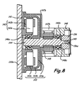
- FIG. 7 is a perspective view of an embodiment of a motor for driving an elevator door
- FIG. 8 is a cross-sectional view of the motor illustrated in FIG. 7
- Illustrated in FIGS. 7 and 8 are vertical portion 130a, driving motor 140, cover 141, fastener 141 a, stator portion 142 with core 142a and coil 142b, rotor portion 143 with disk portion 143a, rim portion 143b, and magnet 143c, rotating shaft 144, driving pulley 145, bearings 146a and 146b, first housing 147 with rotor cover 147a, inner connection 147b, and outer connection 147c, second housing 148 with inner portion 148a, fasteners 148b, cover plate 149, and transducer 156 with rotor 156a.
- FIGS. 7 and 8 show driving motor 140, which has first and second housings 147 and 148 fixed with respect to vertical portion 130a; rotating shaft 144 oriented perpendicularly to vertical portion 130a and being rotatably supported at both its ends; driving pulley 145 coupled to rotating shaft 144; and a driving portion formed of stator 142 and rotor portion 143 for driving rotating shaft 144.
- Cover 141 is provided between vertical portion 130a and first housing 147, and is secured to vertical portion 130a via fasteners such as 141a.
- First housing 147 contains rotor cover 147a, inner connection 147b and outer connection 147c.
- Second housing 148 is attached to inner connection 147b and outer connection 147c through fasteners 148b, which may be machine screws, bolts, or similar structures.
- Second housing 148 may contain cover plate 149 that is generally parallel to cover 141.
- Cover plate 149, first and second housings 147, 148, and cover 141 may be constructed from sheet metal, cast alloys or metals, or polymers.
- transducer 156 Also attached to shaft 144 is transducer 156, which may be either an encoder or resolver, secured by inner portion 148a of second housing 148.
- transducer 156 is a resolver with rotor 156a surrounded by stator windings.
- the driving portion has stator portion 142 radially disposed about rotating shaft 144 and rotor portion 143 relatively rotated with respect to stator portion 142 by a magnetic force.
- Stator portion 142 includes a plurality of cores 142a and coils 142b wound around respective cores 142a.
- Rotor portion 143 includes: disk portion 143a with a central hole; rim portion 143b extending from an edge of disk portion 143a; and a plurality of magnets 143c attached on an inner periphery of rim portion 143b.
- First housing 147 is fixed to vertical portion 130a via the cover 141 while surrounding stator portion 142 and rotor portion 143.
- Second housing 148 is fixed to first housing 147 with driving pulley 145 interposed therebetween.
- Driving motor 140 further has first bearing 146a fixed to cover 141, and second bearing 146b disposed at second housing 148. One end portion and the other end portion of rotating shaft 144 are fitted to first bearing 146a and second
- elevator door driving device 100 can be easily applied without any redesign thereof even when designing an elevator car with higher ceiling plate 116.
- rotating shaft 144 since the one end of rotating shaft 144 is fitted to first bearing 146a, which is supported with respect to vertical portion 130a via cover 141, vertical portion 130a can directly support rotating shaft 144. Therefore, driving motor 140 can be more stably operated while making less vibration. Further, since rotating shaft 144 is rotatably supported via first and second bearings 146a, 146b at both its ends, the load applied to driving pulley 145 during operation of elevator door driving device 100 can be more stably supported. Thus, vibration and noise occurring during movement of doors 121 and 122 can be remarkably reduced, thereby providing a faster driving of doors 121 and 122.
- rotor portion 143 and driving pulley 145 are coupled to rotating shaft 144 in a lengthwise direction thereof.
- driving motor 140 can be transmitted to driving pulley 145 without any loss and driving motor 140 can be configured more compactly.
- the orientation of rotor 143 having disk 143a located outside of bearing 146a instead of adjacent vertical portion 130a provides the advantage of further stability of motor 140.
- prior art motors place the disk portion on the end of shaft 144, next to vertical portion 130a and inside of bearing 146; such a prior art arrangement produces more imbalance in the rotor due to the cantilevered positioning, as well as provides less protection for the motor from outside vibrations on header 130.
- the current arrangement with cover plate 141 and first housing 147 provide better protection from foreign particles, such as dust or water, during assembly and operation of the motor compared to prior art designs.
Claims (14)
- Dispositif (100) pour entraîner une porte d'un ascenseur, comprenant :un linteau de porte (130) monté sur un châssis définissant une entrée de porte (114), le linteau de porte (130) comprenant une partie verticale (130a) sensiblement parallèle à un plan de l'entrée de porte (114) ;une porte (121, 122) supportée de manière mobile sur le châssis (112) ;un moteur d'entraînement (140) disposé sur la partie verticale (130a) du linteau de porte (130), le moteur d'entraînement (140) comprenant :un boîtier (148) fixé par rapport à la partie verticale (130a) ;un arbre de rotation (144) ayant un axe qui est orienté de manière sensiblement perpendiculaire par rapport à la partie verticale (130a), l'arbre de rotation (144) étant supporté en rotation, de manière adjacente à la partie verticale (130a) au niveau de l'une de ses extrémités et étant supporté en rotation par le boîtier (148) au niveau de son autre extrémité ;une poulie d'entraînement (145) couplée à l'arbre de rotation (144) ; etune partie d'entraînement pour entraîner l'arbre de rotation (144) ;la partie d'entraînement comprenant :une partie de stator (142) supportée par la partie verticale (130a) ; etune partie de rotor (143) comprenant :une partie de disque (143a) avec un trou central pour la réception de l'arbre de rotation (144), etune partie de rebord (143b) s'étendant à partir d'un bord de la partie de disque (143a) ;caractérisé en ce que la partie de disque (143a) est agencée du côté opposé de la partie de stator (142) à partir de la partie verticale (130a), la partie de rebord (143b) s'étendant vers la partie verticale (130a).
- Dispositif selon la revendication 1, comprenant en outre :une poulie entraînée (152) prévue sur la partie verticale (130a) éloignée de la poulie d'entraînement (145) ; etune courroie d'entraînement (154) enroulée autour de la poulie d'entraînement (145) et de la poulie entraînée (152), la porte (121, 122) étant fixée à la courroie d'entraînement (154).
- Dispositif selon la revendication 1 ou 2, dans lequel la partie de rotor comprend en outre :une pluralité d'aimants (143c) fixés sur une périphérie interne de la partie de rebord (143b).
- Dispositif selon l'une quelconque des revendications précédentes, dans lequel le moteur d'entraînement (140) comprend en outre :un capteur (156) pour indiquer une position de l'arbre de rotation (144).
- Dispositif selon la revendication 4, dans lequel le capteur (156) est un transformateur contenant une section de rotor (156a) et une section de stator.
- Dispositif selon la revendication 5, dans lequel le transformateur (156) est contenu à l'intérieur du ou d'un deuxième boîtier.
- Dispositif selon l'une quelconque des revendications précédentes, le moteur d'entraînement (140) comprenant en outre :un couvercle de moteur (141) fixé sur la partie verticale (130a) du linteau (130) ;le boîtier (148) étant fixé par rapport au couvercle de moteur (141) ;l'arbre de rotation (144) étant supporté de manière rotative par le couvercle de moteur (141) au niveau de l'une de ses extrémités et étant supporté en rotation par le boîtier (148) au niveau de son autre extrémité.
- Dispositif selon la revendication 7, dans lequel la partie de stator (142) de la partie d'entraînement est fixée sur le couvercle de moteur (141).
- Dispositif selon la revendication 7 ou 8, dans lequel la partie de rebord (143b) s'étend à partir du bord de la partie de disque (143a) vers le couvercle de moteur (141).
- Dispositif selon la revendication 7, 8 ou 9, dans lequel l'arbre (144) est supporté de manière rotative par un palier (146a) en contact avec le couvercle de moteur (141).
- Appareil selon la revendication 10, dans lequel le rotor (145) est fixé sur l'arbre (144) adjacent au palier (146a).
- Cabine d'ascenseur comprenant :au moins une porte d'ascenseur (121, 122) et un dispositif selon l'une quelconque des revendications précédentes, pour entraîner ladite porte.
- Cabine d'ascenseur selon la revendication 12, comprenant en outre :un rail de porte (132) prévu sur la partie verticale (130a) du linteau de porte (130),dans laquelle la au moins une porte (121, 122) est supportée sur le rail (132) par un rouleau supérieur (125b) sur un côté supérieur du rail (132) et un rouleau inférieur (126b) sur un côté inférieur du rail (132).
- Cabine d'ascenseur selon la revendication 13, dans laquelle le rail de porte (132) est monté sur ladite partie verticale (130a) du linteau (130) de manière sensiblement parallèle au plan de l'entrée de porte (114).
Applications Claiming Priority (2)
| Application Number | Priority Date | Filing Date | Title |
|---|---|---|---|
| KR1020070087441A KR20090022262A (ko) | 2007-08-30 | 2007-08-30 | 엘리베이터 도어 구동장치 |
| PCT/US2008/071759 WO2009029380A1 (fr) | 2007-08-30 | 2008-07-31 | Dispositif pour entraîner une porte d'un ascenseur |
Publications (2)
| Publication Number | Publication Date |
|---|---|
| EP2185458A1 EP2185458A1 (fr) | 2010-05-19 |
| EP2185458B1 true EP2185458B1 (fr) | 2011-08-31 |
Family
ID=40387690
Family Applications (1)
| Application Number | Title | Priority Date | Filing Date |
|---|---|---|---|
| EP08828623A Active EP2185458B1 (fr) | 2007-08-30 | 2008-07-31 | Dispositif pour entraîner une porte d'un ascenseur |
Country Status (10)
| Country | Link |
|---|---|
| US (1) | US8727076B2 (fr) |
| EP (1) | EP2185458B1 (fr) |
| JP (1) | JP5256292B2 (fr) |
| KR (2) | KR20090022262A (fr) |
| CN (1) | CN101795955A (fr) |
| AT (1) | ATE522464T1 (fr) |
| BR (1) | BRPI0815780B1 (fr) |
| ES (1) | ES2371226T3 (fr) |
| RU (1) | RU2485042C2 (fr) |
| WO (1) | WO2009029380A1 (fr) |
Families Citing this family (13)
| Publication number | Priority date | Publication date | Assignee | Title |
|---|---|---|---|---|
| KR20090022262A (ko) | 2007-08-30 | 2009-03-04 | 오티스 엘리베이터 컴파니 | 엘리베이터 도어 구동장치 |
| JP5452728B2 (ja) * | 2010-10-04 | 2014-03-26 | 三菱電機株式会社 | エレベータのかご室、及びエレベータのかご |
| KR20120070821A (ko) * | 2010-12-22 | 2012-07-02 | 오티스 엘리베이터 컴파니 | 엘리베이터 카도어 개폐용 모터 |
| CN103492306B (zh) * | 2011-05-12 | 2015-08-05 | 富士达株式会社 | 电梯的门开闭装置 |
| JP5880305B2 (ja) * | 2012-06-19 | 2016-03-09 | フジテック株式会社 | エレベータのドア駆動装置 |
| KR102229239B1 (ko) * | 2012-10-30 | 2021-03-18 | 인벤티오 아게 | 파워 어큐뮬레이터에 의해 야기된 도어 리프의 과속을 방지하기 위한 디바이스 |
| KR101423215B1 (ko) * | 2013-02-27 | 2014-07-25 | 오티스엘리베이터 유한회사 | 엘리베이터 도어 정지장치 |
| CN104418219B (zh) * | 2013-08-26 | 2016-05-11 | 中国船舶重工集团公司第七一三研究所 | 同步带传动式门机 |
| KR101515539B1 (ko) * | 2014-02-26 | 2015-05-04 | (주)부영뉴텍 | 미닫이도어 가이드 행거장치 |
| WO2016030996A1 (fr) * | 2014-08-27 | 2016-03-03 | 三菱電機株式会社 | Dispositif de porte d'ascenseur |
| KR101865413B1 (ko) * | 2016-01-08 | 2018-06-07 | 김택우 | 엘리베이터 카도어 개폐 장치 |
| CN108483200B (zh) * | 2018-03-28 | 2020-04-03 | 日立电梯(中国)有限公司 | 电梯门系统及其驱动装置 |
| CN111332915B (zh) * | 2020-03-03 | 2022-03-25 | 上海吉亿电机有限公司 | 门机马达皮带轮安装结构及安装方法 |
Family Cites Families (25)
| Publication number | Priority date | Publication date | Assignee | Title |
|---|---|---|---|---|
| US3746902A (en) * | 1971-12-30 | 1973-07-17 | Avtron Mfg Inc | Rotor and stator mounting for dynamic machines |
| USRE37058E1 (en) * | 1980-05-10 | 2001-02-20 | Papst Licensing Gmbh & Co. Kg | Disk storage device having contamination seals |
| US5216557A (en) * | 1981-09-07 | 1993-06-01 | Papst-Motoren Gmbh & Co. Kg | Disk storage device having a brushless dc drive motor |
| DE3327123C2 (de) * | 1982-07-27 | 1996-07-11 | Papst Motoren Gmbh & Co Kg | Antriebsanordnung für signalverarbeitende Geräte |
| ATE54517T1 (de) * | 1985-09-23 | 1990-07-15 | Siemens Ag | Elektromotor, insbesondere dauermagneterregter aussenlaeufermotor. |
| FI93632C (fi) | 1993-06-28 | 1995-05-10 | Kone Oy | Alakoneistoinen vetopyörähissi |
| US5612518A (en) * | 1994-04-08 | 1997-03-18 | Otis Elevator Company | Linear induction motor door drive assembly for elevators |
| FI97800C (fi) * | 1994-10-31 | 1997-02-25 | Kone Oy | Hissin oven yläkannatinpalkki ja ovikoneistojärjestely |
| CA2259933A1 (fr) | 1996-07-25 | 1998-02-05 | Inventio Ag | Dispositif d'entrainement de porte |
| US5711112A (en) * | 1996-09-03 | 1998-01-27 | Otis Elevator Company | Double-drive automatic sliding door operator |
| US5878846A (en) | 1996-10-07 | 1999-03-09 | Vertisys, Inc. | Light duty elevator door operator |
| US5756946A (en) | 1996-11-07 | 1998-05-26 | Otis Elevator Company | Flexible mounting of a motor secondary in a linear induction motor for driving elevator car doors |
| US5841082A (en) | 1996-11-07 | 1998-11-24 | Otis Elevator Company | Secondary guidance system for linear induction motors driving elevator car doors |
| US7246688B2 (en) * | 1998-12-23 | 2007-07-24 | Otis Elevator Company | Elevator door system |
| JP2001226058A (ja) * | 2000-02-10 | 2001-08-21 | Mitsubishi Electric Corp | エレベータのドア装置 |
| KR100407006B1 (ko) * | 2000-04-06 | 2003-11-28 | 스미도모쥬기가이고교 가부시키가이샤 | 벨트식 도어개폐용 구동장치 |
| JP4531899B2 (ja) | 2001-06-06 | 2010-08-25 | 三菱電機株式会社 | エレベータのかごドア装置 |
| FR2830245B1 (fr) | 2001-09-28 | 2004-01-02 | Otis Elevator Co | Dispositif d'entrainement compact notamment pour la translation des portes de cabine d'ascenseur,ensemble moteur et reducteur de vitesse utilise et linteau support |
| JP4152673B2 (ja) * | 2002-06-03 | 2008-09-17 | 日本オーチス・エレベータ株式会社 | エレベータのドア駆動装置 |
| US6943508B2 (en) | 2002-09-23 | 2005-09-13 | Otis Elevator Company | Tubular linear synchronous motor control for elevator doors |
| JP2004338850A (ja) * | 2003-05-14 | 2004-12-02 | Toshiba Elevator Co Ltd | エレベータドアの駆動装置 |
| FI20041157A (fi) * | 2004-09-07 | 2005-09-08 | Kone Corp | Hissijärjestely |
| JP4791810B2 (ja) * | 2005-12-02 | 2011-10-12 | オーチス エレベータ カンパニー | エレベータのドア駆動装置 |
| DE102006059779B4 (de) | 2006-12-15 | 2010-06-24 | Heraeus Quarzglas Gmbh & Co. Kg | Verfahren für die Herstellung eines Hohlzylinders aus synthetischem Quarzglas, nach dem Verfahren erhaltener dickwandiger Hohlzylinder und Verfahren zur Herstellung einer Vorform für optische Fasern |
| KR20090022262A (ko) | 2007-08-30 | 2009-03-04 | 오티스 엘리베이터 컴파니 | 엘리베이터 도어 구동장치 |
-
2007
- 2007-08-30 KR KR1020070087441A patent/KR20090022262A/ko not_active Application Discontinuation
-
2008
- 2008-07-31 RU RU2010112457/11A patent/RU2485042C2/ru not_active IP Right Cessation
- 2008-07-31 CN CN200880105030A patent/CN101795955A/zh active Pending
- 2008-07-31 ES ES08828623T patent/ES2371226T3/es active Active
- 2008-07-31 BR BRPI0815780-4A patent/BRPI0815780B1/pt active IP Right Grant
- 2008-07-31 AT AT08828623T patent/ATE522464T1/de not_active IP Right Cessation
- 2008-07-31 EP EP08828623A patent/EP2185458B1/fr active Active
- 2008-07-31 US US12/672,668 patent/US8727076B2/en active Active
- 2008-07-31 JP JP2010523011A patent/JP5256292B2/ja not_active Expired - Fee Related
- 2008-07-31 WO PCT/US2008/071759 patent/WO2009029380A1/fr active Application Filing
- 2008-07-31 KR KR1020107004374A patent/KR101207910B1/ko active IP Right Grant
Also Published As
| Publication number | Publication date |
|---|---|
| RU2010112457A (ru) | 2011-10-10 |
| BRPI0815780B1 (pt) | 2019-10-01 |
| RU2485042C2 (ru) | 2013-06-20 |
| KR20100040944A (ko) | 2010-04-21 |
| BRPI0815780A2 (pt) | 2015-02-24 |
| KR101207910B1 (ko) | 2012-12-04 |
| US8727076B2 (en) | 2014-05-20 |
| EP2185458A1 (fr) | 2010-05-19 |
| WO2009029380A1 (fr) | 2009-03-05 |
| KR20090022262A (ko) | 2009-03-04 |
| JP5256292B2 (ja) | 2013-08-07 |
| ATE522464T1 (de) | 2011-09-15 |
| US20110198158A1 (en) | 2011-08-18 |
| CN101795955A (zh) | 2010-08-04 |
| JP2011514298A (ja) | 2011-05-06 |
| ES2371226T3 (es) | 2011-12-28 |
Similar Documents
| Publication | Publication Date | Title |
|---|---|---|
| EP2185458B1 (fr) | Dispositif pour entraîner une porte d'un ascenseur | |
| JP3784644B2 (ja) | エレベータドアシステム | |
| JP2777340B2 (ja) | エレベータ機械装置 | |
| EP1630120B1 (fr) | Treuil et moteur d'ascenseur | |
| FI106192B (fi) | Hissin nostokoneisto | |
| JP5848825B2 (ja) | エレベータローラガイド | |
| JP4550120B2 (ja) | エレベータ用巻上機 | |
| EP1396461B1 (fr) | Dispositif de porte de cabine d'ascenseur | |
| JPWO2005019085A1 (ja) | エレベータ用薄形巻上機 | |
| EP3444218B1 (fr) | Moteur d'ascenseur à aimant permanent à flux radial | |
| JP6568032B2 (ja) | 巻上機及びエレベーター | |
| KR20040019493A (ko) | 엘리베이터용 박형 권상기 | |
| JP4152673B2 (ja) | エレベータのドア駆動装置 | |
| JP4167546B2 (ja) | 自動ドア用アウタロータ型ブラシレスモータ | |
| EP1727761B1 (fr) | Ascenseur | |
| JPH10152274A (ja) | ロープ式エレベータ | |
| KR20060026005A (ko) | 엘리베이터용 권상기 |
Legal Events
| Date | Code | Title | Description |
|---|---|---|---|
| PUAI | Public reference made under article 153(3) epc to a published international application that has entered the european phase |
Free format text: ORIGINAL CODE: 0009012 |
|
| 17P | Request for examination filed |
Effective date: 20100225 |
|
| AK | Designated contracting states |
Kind code of ref document: A1 Designated state(s): AT BE BG CH CY CZ DE DK EE ES FI FR GB GR HR HU IE IS IT LI LT LU LV MC MT NL NO PL PT RO SE SI SK TR |
|
| AX | Request for extension of the european patent |
Extension state: AL BA MK RS |
|
| RIN1 | Information on inventor provided before grant (corrected) |
Inventor name: LEE, JIN KOO |
|
| DAX | Request for extension of the european patent (deleted) | ||
| GRAP | Despatch of communication of intention to grant a patent |
Free format text: ORIGINAL CODE: EPIDOSNIGR1 |
|
| GRAS | Grant fee paid |
Free format text: ORIGINAL CODE: EPIDOSNIGR3 |
|
| GRAA | (expected) grant |
Free format text: ORIGINAL CODE: 0009210 |
|
| AK | Designated contracting states |
Kind code of ref document: B1 Designated state(s): AT BE BG CH CY CZ DE DK EE ES FI FR GB GR HR HU IE IS IT LI LT LU LV MC MT NL NO PL PT RO SE SI SK TR |
|
| REG | Reference to a national code |
Ref country code: GB Ref legal event code: FG4D Ref country code: CH Ref legal event code: EP |
|
| REG | Reference to a national code |
Ref country code: IE Ref legal event code: FG4D |
|
| REG | Reference to a national code |
Ref country code: DE Ref legal event code: R096 Ref document number: 602008009375 Country of ref document: DE Effective date: 20111103 |
|
| REG | Reference to a national code |
Ref country code: NL Ref legal event code: VDEP Effective date: 20110831 Ref country code: ES Ref legal event code: FG2A Ref document number: 2371226 Country of ref document: ES Kind code of ref document: T3 Effective date: 20111228 |
|
| LTIE | Lt: invalidation of european patent or patent extension |
Effective date: 20110831 |
|
| PG25 | Lapsed in a contracting state [announced via postgrant information from national office to epo] |
Ref country code: NO Free format text: LAPSE BECAUSE OF FAILURE TO SUBMIT A TRANSLATION OF THE DESCRIPTION OR TO PAY THE FEE WITHIN THE PRESCRIBED TIME-LIMIT Effective date: 20111130 Ref country code: FI Free format text: LAPSE BECAUSE OF FAILURE TO SUBMIT A TRANSLATION OF THE DESCRIPTION OR TO PAY THE FEE WITHIN THE PRESCRIBED TIME-LIMIT Effective date: 20110831 Ref country code: NL Free format text: LAPSE BECAUSE OF FAILURE TO SUBMIT A TRANSLATION OF THE DESCRIPTION OR TO PAY THE FEE WITHIN THE PRESCRIBED TIME-LIMIT Effective date: 20110831 Ref country code: SE Free format text: LAPSE BECAUSE OF FAILURE TO SUBMIT A TRANSLATION OF THE DESCRIPTION OR TO PAY THE FEE WITHIN THE PRESCRIBED TIME-LIMIT Effective date: 20110831 Ref country code: HR Free format text: LAPSE BECAUSE OF FAILURE TO SUBMIT A TRANSLATION OF THE DESCRIPTION OR TO PAY THE FEE WITHIN THE PRESCRIBED TIME-LIMIT Effective date: 20110831 Ref country code: LT Free format text: LAPSE BECAUSE OF FAILURE TO SUBMIT A TRANSLATION OF THE DESCRIPTION OR TO PAY THE FEE WITHIN THE PRESCRIBED TIME-LIMIT Effective date: 20110831 Ref country code: IS Free format text: LAPSE BECAUSE OF FAILURE TO SUBMIT A TRANSLATION OF THE DESCRIPTION OR TO PAY THE FEE WITHIN THE PRESCRIBED TIME-LIMIT Effective date: 20111231 |
|
| REG | Reference to a national code |
Ref country code: AT Ref legal event code: MK05 Ref document number: 522464 Country of ref document: AT Kind code of ref document: T Effective date: 20110831 |
|
| PG25 | Lapsed in a contracting state [announced via postgrant information from national office to epo] |
Ref country code: GR Free format text: LAPSE BECAUSE OF FAILURE TO SUBMIT A TRANSLATION OF THE DESCRIPTION OR TO PAY THE FEE WITHIN THE PRESCRIBED TIME-LIMIT Effective date: 20111201 Ref country code: AT Free format text: LAPSE BECAUSE OF FAILURE TO SUBMIT A TRANSLATION OF THE DESCRIPTION OR TO PAY THE FEE WITHIN THE PRESCRIBED TIME-LIMIT Effective date: 20110831 Ref country code: LV Free format text: LAPSE BECAUSE OF FAILURE TO SUBMIT A TRANSLATION OF THE DESCRIPTION OR TO PAY THE FEE WITHIN THE PRESCRIBED TIME-LIMIT Effective date: 20110831 Ref country code: SI Free format text: LAPSE BECAUSE OF FAILURE TO SUBMIT A TRANSLATION OF THE DESCRIPTION OR TO PAY THE FEE WITHIN THE PRESCRIBED TIME-LIMIT Effective date: 20110831 Ref country code: CY Free format text: LAPSE BECAUSE OF FAILURE TO SUBMIT A TRANSLATION OF THE DESCRIPTION OR TO PAY THE FEE WITHIN THE PRESCRIBED TIME-LIMIT Effective date: 20110831 |
|
| PG25 | Lapsed in a contracting state [announced via postgrant information from national office to epo] |
Ref country code: BE Free format text: LAPSE BECAUSE OF FAILURE TO SUBMIT A TRANSLATION OF THE DESCRIPTION OR TO PAY THE FEE WITHIN THE PRESCRIBED TIME-LIMIT Effective date: 20110831 |
|
| PG25 | Lapsed in a contracting state [announced via postgrant information from national office to epo] |
Ref country code: CZ Free format text: LAPSE BECAUSE OF FAILURE TO SUBMIT A TRANSLATION OF THE DESCRIPTION OR TO PAY THE FEE WITHIN THE PRESCRIBED TIME-LIMIT Effective date: 20110831 Ref country code: SK Free format text: LAPSE BECAUSE OF FAILURE TO SUBMIT A TRANSLATION OF THE DESCRIPTION OR TO PAY THE FEE WITHIN THE PRESCRIBED TIME-LIMIT Effective date: 20110831 |
|
| PG25 | Lapsed in a contracting state [announced via postgrant information from national office to epo] |
Ref country code: PL Free format text: LAPSE BECAUSE OF FAILURE TO SUBMIT A TRANSLATION OF THE DESCRIPTION OR TO PAY THE FEE WITHIN THE PRESCRIBED TIME-LIMIT Effective date: 20110831 Ref country code: PT Free format text: LAPSE BECAUSE OF FAILURE TO SUBMIT A TRANSLATION OF THE DESCRIPTION OR TO PAY THE FEE WITHIN THE PRESCRIBED TIME-LIMIT Effective date: 20120102 Ref country code: RO Free format text: LAPSE BECAUSE OF FAILURE TO SUBMIT A TRANSLATION OF THE DESCRIPTION OR TO PAY THE FEE WITHIN THE PRESCRIBED TIME-LIMIT Effective date: 20110831 Ref country code: EE Free format text: LAPSE BECAUSE OF FAILURE TO SUBMIT A TRANSLATION OF THE DESCRIPTION OR TO PAY THE FEE WITHIN THE PRESCRIBED TIME-LIMIT Effective date: 20110831 |
|
| PG25 | Lapsed in a contracting state [announced via postgrant information from national office to epo] |
Ref country code: DK Free format text: LAPSE BECAUSE OF FAILURE TO SUBMIT A TRANSLATION OF THE DESCRIPTION OR TO PAY THE FEE WITHIN THE PRESCRIBED TIME-LIMIT Effective date: 20110831 |
|
| PLBE | No opposition filed within time limit |
Free format text: ORIGINAL CODE: 0009261 |
|
| STAA | Information on the status of an ep patent application or granted ep patent |
Free format text: STATUS: NO OPPOSITION FILED WITHIN TIME LIMIT |
|
| 26N | No opposition filed |
Effective date: 20120601 |
|
| REG | Reference to a national code |
Ref country code: DE Ref legal event code: R097 Ref document number: 602008009375 Country of ref document: DE Effective date: 20120601 |
|
| PG25 | Lapsed in a contracting state [announced via postgrant information from national office to epo] |
Ref country code: MC Free format text: LAPSE BECAUSE OF NON-PAYMENT OF DUE FEES Effective date: 20120731 |
|
| REG | Reference to a national code |
Ref country code: CH Ref legal event code: PL |
|
| PG25 | Lapsed in a contracting state [announced via postgrant information from national office to epo] |
Ref country code: LI Free format text: LAPSE BECAUSE OF NON-PAYMENT OF DUE FEES Effective date: 20120731 Ref country code: CH Free format text: LAPSE BECAUSE OF NON-PAYMENT OF DUE FEES Effective date: 20120731 |
|
| REG | Reference to a national code |
Ref country code: IE Ref legal event code: MM4A |
|
| PG25 | Lapsed in a contracting state [announced via postgrant information from national office to epo] |
Ref country code: BG Free format text: LAPSE BECAUSE OF FAILURE TO SUBMIT A TRANSLATION OF THE DESCRIPTION OR TO PAY THE FEE WITHIN THE PRESCRIBED TIME-LIMIT Effective date: 20111130 |
|
| PG25 | Lapsed in a contracting state [announced via postgrant information from national office to epo] |
Ref country code: MT Free format text: LAPSE BECAUSE OF FAILURE TO SUBMIT A TRANSLATION OF THE DESCRIPTION OR TO PAY THE FEE WITHIN THE PRESCRIBED TIME-LIMIT Effective date: 20110831 Ref country code: IE Free format text: LAPSE BECAUSE OF NON-PAYMENT OF DUE FEES Effective date: 20120731 |
|
| PG25 | Lapsed in a contracting state [announced via postgrant information from national office to epo] |
Ref country code: LU Free format text: LAPSE BECAUSE OF NON-PAYMENT OF DUE FEES Effective date: 20120731 |
|
| PG25 | Lapsed in a contracting state [announced via postgrant information from national office to epo] |
Ref country code: HU Free format text: LAPSE BECAUSE OF FAILURE TO SUBMIT A TRANSLATION OF THE DESCRIPTION OR TO PAY THE FEE WITHIN THE PRESCRIBED TIME-LIMIT Effective date: 20080731 |
|
| PGFP | Annual fee paid to national office [announced via postgrant information from national office to epo] |
Ref country code: GB Payment date: 20140730 Year of fee payment: 7 |
|
| PGFP | Annual fee paid to national office [announced via postgrant information from national office to epo] |
Ref country code: TR Payment date: 20150707 Year of fee payment: 8 |
|
| PGFP | Annual fee paid to national office [announced via postgrant information from national office to epo] |
Ref country code: IT Payment date: 20150626 Year of fee payment: 8 |
|
| GBPC | Gb: european patent ceased through non-payment of renewal fee |
Effective date: 20150731 |
|
| PG25 | Lapsed in a contracting state [announced via postgrant information from national office to epo] |
Ref country code: GB Free format text: LAPSE BECAUSE OF NON-PAYMENT OF DUE FEES Effective date: 20150731 |
|
| REG | Reference to a national code |
Ref country code: FR Ref legal event code: PLFP Year of fee payment: 9 |
|
| REG | Reference to a national code |
Ref country code: FR Ref legal event code: PLFP Year of fee payment: 10 |
|
| REG | Reference to a national code |
Ref country code: DE Ref legal event code: R082 Ref document number: 602008009375 Country of ref document: DE Representative=s name: SCHMITT-NILSON SCHRAUD WAIBEL WOHLFROM PATENTA, DE |
|
| PG25 | Lapsed in a contracting state [announced via postgrant information from national office to epo] |
Ref country code: IT Free format text: LAPSE BECAUSE OF NON-PAYMENT OF DUE FEES Effective date: 20160731 |
|
| REG | Reference to a national code |
Ref country code: FR Ref legal event code: PLFP Year of fee payment: 11 |
|
| PGFP | Annual fee paid to national office [announced via postgrant information from national office to epo] |
Ref country code: FR Payment date: 20230621 Year of fee payment: 16 |
|
| PGFP | Annual fee paid to national office [announced via postgrant information from national office to epo] |
Ref country code: ES Payment date: 20230801 Year of fee payment: 16 |
|
| PGFP | Annual fee paid to national office [announced via postgrant information from national office to epo] |
Ref country code: DE Payment date: 20230620 Year of fee payment: 16 |