EP2185362B1 - Workpiece processing system and method - Google Patents
Workpiece processing system and method Download PDFInfo
- Publication number
- EP2185362B1 EP2185362B1 EP08806199.9A EP08806199A EP2185362B1 EP 2185362 B1 EP2185362 B1 EP 2185362B1 EP 08806199 A EP08806199 A EP 08806199A EP 2185362 B1 EP2185362 B1 EP 2185362B1
- Authority
- EP
- European Patent Office
- Prior art keywords
- feed
- wafers
- wafer
- output
- input
- Prior art date
- Legal status (The legal status is an assumption and is not a legal conclusion. Google has not performed a legal analysis and makes no representation as to the accuracy of the status listed.)
- Active
Links
Images




Classifications
-
- H—ELECTRICITY
- H05—ELECTRIC TECHNIQUES NOT OTHERWISE PROVIDED FOR
- H05K—PRINTED CIRCUITS; CASINGS OR CONSTRUCTIONAL DETAILS OF ELECTRIC APPARATUS; MANUFACTURE OF ASSEMBLAGES OF ELECTRICAL COMPONENTS
- H05K3/00—Apparatus or processes for manufacturing printed circuits
- H05K3/10—Apparatus or processes for manufacturing printed circuits in which conductive material is applied to the insulating support in such a manner as to form the desired conductive pattern
- H05K3/12—Apparatus or processes for manufacturing printed circuits in which conductive material is applied to the insulating support in such a manner as to form the desired conductive pattern using thick film techniques, e.g. printing techniques to apply the conductive material or similar techniques for applying conductive paste or ink patterns
- H05K3/1216—Apparatus or processes for manufacturing printed circuits in which conductive material is applied to the insulating support in such a manner as to form the desired conductive pattern using thick film techniques, e.g. printing techniques to apply the conductive material or similar techniques for applying conductive paste or ink patterns by screen printing or stencil printing
-
- B—PERFORMING OPERATIONS; TRANSPORTING
- B41—PRINTING; LINING MACHINES; TYPEWRITERS; STAMPS
- B41F—PRINTING MACHINES OR PRESSES
- B41F15/00—Screen printers
- B41F15/08—Machines
-
- H—ELECTRICITY
- H05—ELECTRIC TECHNIQUES NOT OTHERWISE PROVIDED FOR
- H05K—PRINTED CIRCUITS; CASINGS OR CONSTRUCTIONAL DETAILS OF ELECTRIC APPARATUS; MANUFACTURE OF ASSEMBLAGES OF ELECTRICAL COMPONENTS
- H05K13/00—Apparatus or processes specially adapted for manufacturing or adjusting assemblages of electric components
- H05K13/0061—Tools for holding the circuit boards during processing; handling transport of printed circuit boards
Definitions
- the present invention relates to a wafer processing system for and method of processing wafers, including solar cell wafers, and in particular a screen printing system for and method of printing wafers.
- a wafer processing system for and method of processing wafers including solar cell wafers, and in particular a screen printing system for and method of printing wafers.
- SMT manufacturing comprises three basic processes, namely, printing of material deposits on a substrate, including printing of solder deposits, placement of components on the printed substrate and re-flow of the printed deposits.
- the manufacturing equipment comprises machines in an in-line configuration, which are interconnected by conveyors which pass through the machines, with the substrates first passing to a printing machine for the printing of material deposits, then to a pick-and-place machine at which components are placed on the printed substrate, and finally a re-flow machine where the assembly is rendered homogeneous.
- the printing screen includes a plurality of images, one for each track, which allow patterns of deposit to be printed simultaneously on multiple substrates in a single printing operation.
- Solar cell manufacturing requires the printing of images on the upper and lower sides of wafers, and the subsequent firing of the printed wafers. Typically, one image is printed on the upper side of a wafer and two images are printed on the underside of a wafer.
- a conventional production line includes nine separate processing machines, these being a wafer loader for loading wafers onto the production line, a first printer for printing a first print onto one side of a wafer, a first dryer for drying the printed wafer, a flipper for inverting the wafer, a second printer for printing a second print onto the other side of the wafer, a second dryer for drying the printed wafer, a third printer for printing a third print onto the other side of the wafer, a firing furnace for firing the printed wafer and an unloader for unloading finished wafers from the production line.
- a wafer loader for loading wafers onto the production line
- a first printer for printing a first print onto one side of a wafer
- a first dryer for drying the printed wafer
- a flipper for inverting the wafer
- a second printer for printing a second print onto the other side of the wafer
- a second dryer for drying the printed wafer
- a third printer for printing a third print
- hot-melt printing process has been developed for the printing of contact fingers on solar cell wafers, which eliminates the need for the drying operations.
- the use of hot-melt printing reduces the number of separate machines to seven, in not requiring the conventional dryers, but still a large number of machines are required, which require a large area.
- US-A-5906158 discloses a screen printing apparatus, a feed-in unit which provides substrates individually to the screen printing apparatus and a feed-out unit which removes substrates individually from the screen printing apparatus following a printing operation.
- US-A-5730051 discloses a screen printing machine having a carry-in conveyor, a carry-out conveyor and a positioning stage arranged therebetween, over which an object is successively transferred.
- US-A-2004/0247417 discloses an intermediate product transferring apparatus for transferring an intermediate product between a single-wafer carrying line for carrying the intermediate product in a single-wafer manner and a manufacturing apparatus for manufacturing the intermediate product.
- the present invention provides a wafer processing system, characterized by a plurality of wafer processing modules which are disposed in parallel relation and each separably operable to process wafers, each comprising a wafer processing unit for processing wafers and a feed unit for transferring wafers to and from the wafer processing unit, wherein the feed unit comprises input and output feed assemblies for transferring wafers to and from the wafer processing unit which provides a wafer processing station and a processing zone feed assembly which interconnects the input and output feed assemblies for transferring wafers from the input feed assembly to the wafer processing unit and from the wafer processing unit to the output feed assembly, and the output feed assemblies together provide at least one common output feed along which wafers are transferred.
- the present invention provides a method of processing wafers, characterized by the steps of: providing a plurality of wafer processing modules which are disposed in parallel relation and each separably operable to process wafers, each wafer processing module comprising a wafer processing unit for processing wafers and a feed unit for transferring wafers to and from the wafer processing unit, wherein the feed unit comprises input and output feed assemblies for transferring wafers to and from the wafer processing unit which provides a wafer processing station and a processing zone feed assembly which interconnects the input and output feed assemblies for transferring wafers from the input feed assembly to the wafer processing unit and from the wafer processing unit to the output feed assembly, and the output feed assemblies together provide at least one common output feed along which wafers are transferred; and transferring wafers to and from the wafer processing units and along the at least one common output feed.
- FIGS 1 to 4 illustrate a workpiece-processing system, in this embodiment a screen printing system, in accordance with a first embodiment of the present invention.
- the screen printing system comprises at least one workpiece-processing module, in this embodiment a plurality of workpiece-processing modules 3a, 3b, 3c, here print modules, which are disposed in parallel relation and each separably operable to print deposits of a print medium onto workpieces W.
- Each print module 3a, 3b, 3c comprises a support unit 5, which comprises a lower, base support member 7, in this embodiment a frame member, which rests on the ground, and an upper support member 9, in this embodiment a frame member, which is mounted on the lower support member 7.
- the lower support members 7 of the print modules 3a, 3b, 3c are provided as a single integral structure.
- the lower support members 7 of the print modules 3a, 3b, 3c could be separate structures which are fixed together, such as fixed together by fixing bolts.
- the upper support members 9 of the print modules 3a, 3b, 3c are provided as separate structures.
- Each print module 3a, 3b, 3c further comprises a workpiece-processing unit 11, in this embodiment a print unit, which is mounted to the upper support member 9 and operable to print deposits of a print medium onto successive workpieces W.
- the print unit 11 comprises a screen support member 15 for supporting a printing screen PS, a print head 19 which is movable over the printing screen PS to print deposits of a print medium through a pattern of apertures in the printing screen PS and onto a workpiece W supported therebelow, and a drive mechanism 21 for driving the print head 19 over the printing screen PS in a printing operation.
- the print head 19 is an enclosed print head, which is driveable in a reciprocating manner over the printing screen PS, such as to print in each of the opposite directions of movement.
- the print head 19 could be of any other suitable design, such as a squeegee, and could be operable such as to print in only one direction of movement.
- each print module 3a, 3b, 3c further comprises a workpiece support assembly 22 which receives a workpiece W and supports the same beneath the printing screen PS.
- the workpiece support assembly 22 comprises a workpiece support unit 23 which supports a workpiece W, and an alignment mechanism 24 for aligning a supported workpiece W relative to the printing screen PS.
- the workpiece support unit 23 comprises a workpiece support member 25, which is movable vertically and provides a print station, and a lifting mechanism 26, which is operable to raise and lower the workpiece support member 25.
- the workpiece support member 25 is movable between a first, lowered, loading position, in which the workpiece support member 25 can be loaded with a workpiece W and a second, raised, workpiece-processing, here printing position, in which the workpiece W is set at a position beneath the printing screen PS for printing.
- the printing system of the present invention allows for both on-contact and off-contact printing.
- the workpiece support member 25 comprises a workpiece-processing table 27, here a print table, in this embodiment in the form of a platen, which includes a vacuum section 28, here centrally located, which is operative to hold a workpiece W thereto.
- a workpiece-processing table 27 here a print table, in this embodiment in the form of a platen, which includes a vacuum section 28, here centrally located, which is operative to hold a workpiece W thereto.
- the vacuum section 28 comprises a pad, here a sintered plate, typically a sintered ceramic plate, which is set in the print table 27, such as to define a planar upper surface, and provides for a vacuum at the upper surface thereof on application of a vacuum source to the lower surface thereof.
- a sintered plate typically a sintered ceramic plate
- the workpiece support member 25 further comprises a plurality of workpiece support elements 29, here upstanding pillars, which extend through the print table 27 and are biased downwardly by resilient elements 30, here compression springs.
- the resilient elements 30 are configured to act against respective stops 31, such that, when the print table 27 is in the lowered, loading position, the resilient elements 30 are compressed and the workpiece support elements 29 project above the upper surface of the print table 27, such as to receive a workpiece W thereon in spaced relation from the upper surface of the print table 27, and, when the print table 27 is in the raised, printing position, the workpiece support elements 29 are at or below the upper surface of the print table 27, here flush to the upper surface of the print table 27, whereby the lower surface of the workpiece W is fully supported by the upper surface of the print table 27.
- the print table 27 includes at least one, here a plurality of windows 32, which allow for a line of sight to edges of a supported workpiece W and alignment marks, often referred to as fiducials, on the lower surface of the printing screen PS.
- the lifting mechanism 26 comprises a leadscrew 33, which is threadably coupled to the print table 27, such that rotation of the leadscrew 33 in the opposite, clockwise and counter-clockwise senses causes a respective one of the raising or lowering of the print table 27, and an actuator 34 for rotating the leadscrew 33.
- the actuator 34 comprises a drive motor and an associated gearbox assembly.
- the alignment mechanism 24 comprises at least one, in this embodiment a plurality of camera units 35, which are configured such as to view edges of a supported workpiece W and the alignment marks on the lower surface of the printing screen PS through respective ones of the windows 32 in the print table 27, and an actuator unit 36 which includes a plurality of actuators, here drive motors, which are operable, in response to the images as acquired by the camera units 35, to correct any misalignment in the supported workpiece W relative to the printing screen PS.
- a plurality of camera units 35 which are configured such as to view edges of a supported workpiece W and the alignment marks on the lower surface of the printing screen PS through respective ones of the windows 32 in the print table 27, and an actuator unit 36 which includes a plurality of actuators, here drive motors, which are operable, in response to the images as acquired by the camera units 35, to correct any misalignment in the supported workpiece W relative to the printing screen PS.
- the actuator unit 36 comprises three actuators for positioning the workpiece W in X, Y and ⁇ axes.
- the actuator unit 36 could comprise any number and arrangement of actuators which are such as to enable alignment of a supported workpiece W relative to the printing screen PS.
- the workpiece W is moved in relation to the printing screen PS in order to achieve alignment of the workpiece W relative to the printing screen PS
- the printing screen PS could be moved in relation to the workpiece W in order to achieve alignment of the workpiece W relative to the printing screen PS.
- Each print module 3a, 3b, 3c further comprises a feed unit 37 which is mounted to the upper support member 9 and operable to transfer workpieces W to and from the print unit 11.
- the feed unit 37 comprises input and output feed assemblies 38, 39, in this embodiment disposed in parallel relation to opposite sides of the print unit 11, which are operable to transfer workpieces W to and from the print module 3a, 3b, 3c, and a print zone feed assembly 40, which interconnects the input and output feed assemblies 38, 39 and is operable to transfer workpieces W from the input feed assembly 38 to the workpiece support member 25 of the workpiece support unit 23 for printing and, following printing, from the workpiece support member 25 of the workpiece support unit 23 to the output feed assembly 39.
- the input and output feed assemblies 38, 39 are operable to feed workpieces W in common feed directions F1, F2, but in another embodiment the feed directions F1, F2 could be opposite directions.
- the input feed assembly 38 comprises first, second and third sub-feed assemblies 38a, 38b, 38c, which are individually operable, with the primary function of the input feed assembly 38 being to maintain a workpiece W for transfer to the print zone feed assembly 40 and transfer workpieces W to any downstream print modules 3a, 3b, 3c, as will be described in more detail hereinbelow.
- the first, loading sub-feed assembly 38a provides a loading station from which a workpiece W can be loaded into the print unit 11.
- the second, upline buffer sub-feed assembly 38b is upstream of the loading sub-feed assembly 38a and provides an upline buffer station which buffers a workpiece W for transfer downstream to the loading sub-feed assembly 38a.
- the third, downline buffer sub-feed assembly 38c is downstream of the loading sub-feed assembly 38a and provides a downline buffer station which buffers a workpiece W for transfer downstream.
- Each of the sub-feed assemblies 38a, 38b, 38c comprises a pair of drive elements 41, 41, in this embodiment belts, here toothed belts, which are disposed in spaced, parallel relation such as to engage the opposite, lower edges of a workpiece W, and an actuator 45, in this embodiment a drive motor, which is commonly coupled, in this embodiment by a pulley arrangement 47, to the drive elements 41, 41, such that the drive elements 41, 41 are commonly driven by the actuator 45.
- the inner drive element 41 of the first, loading sub-feed assembly 38a is configured, here by an arrangement of pulleys, such as to comprise first and second spaced drive element sections, which accommodate a walking beam 95 therebetween, as will be described in more detail hereinbelow.
- Each of the sub-feed assemblies 38a, 38b, 38c further comprises a sensor unit 51 which comprises first and second sensors 53, 55, which are disposed in downstream relation in the input feed direction F1.
- the sensors 53, 55 are configured such that the actuator 45 drives the drive elements 41, 41 at a first, transfer speed until the leading edge of a workpiece W is detected by the first, upstream sensor 53, on detection of the leading edge of the workpiece W by the first sensor 53, the actuator 45 drives the drive elements 41, 41 at a second, slower speed, which allows for accurate positioning of the workpiece W, and, on detection of the leading edge of the workpiece W by the second, downstream sensor 55, the actuator 45 is stopped to position the workpiece W at the required position.
- the output feed assembly 39 comprises first, second and third sub-feed assemblies 39a, 39b, 39c, which are individually operable, with the primary function of the output feed assembly 39 being to receive workpieces W from the print zone feed assembly 40 and transfer the same downstream, as will be described in more detail hereinbelow.
- the first, unloading sub-feed assembly 39a provides an unloading station to which a workpiece W is unloaded from the print unit 11.
- the second, upline buffer sub-feed assembly 39b is upstream of the unloading sub-feed assembly 39a and provides an upline buffer station which buffers a workpiece W for transfer downstream.
- the third, downline buffer sub-feed assembly 39c is downstream of the unloading sub-feed assembly 39a and provides a downline buffer station which buffers a workpiece W for transfer downstream.
- Each of the sub-feed assemblies 39a, 39b, 39c comprises a pair of drive elements 61, 61, in this embodiment belts, here toothed belts, which are disposed in spaced parallel relation such as to engage the opposite, lower edges of a workpiece W, and an actuator 65, in this embodiment a drive motor, which is commonly coupled, in this embodiment by a pulley arrangement 67, to the drive elements 61, 61, such that the drive elements 61, 61 are commonly driven by the actuator 65.
- the inner drive element 61 of the first, unloading sub-feed assembly 39a is configured, here by an arrangement of pulleys, such as to comprise first and second spaced drive element sections, which accommodate a walking beam 125 therebetween, as will be described in more detail hereinbelow.
- Each of the sub-feed assemblies 39a, 39b, 39c further comprises a sensor unit 71 which comprises first and second sensors 73, 75 which are disposed in downstream relation in the output feed direction F2.
- the sensors 73, 75 are configured such that the actuator 65 drives the drive elements 61, 61 at a first, transfer speed until the leading edge of a workpiece W is detected by the first, upstream sensor 73, on detection of the leading edge of the workpiece W by the first sensor 73, the actuator 65 drives the drive elements 61, 61 at a second, slower speed, which allows for accurate positioning of the workpiece W, and, on detection of the leading edge of the workpiece W by the second, downstream sensor 75, the actuator 65 is stopped to position the workpiece W at the required position.
- the print zone feed assembly 40 comprises an input transfer station 81, which is disposed adjacent, in this embodiment inwardly adjacent, the loading station 38a, and an input transfer unit 85, which is operable to transfer workpieces W from the loading station 38a to the input transfer station 81 and from the input transfer station 81 to the printing station.
- the input transfer station 81 comprises a plurality of workpiece support elements 87, here four fixed, upstanding pillars which are arranged in the form of a square.
- workpiece support elements 87 here four fixed, upstanding pillars which are arranged in the form of a square.
- any number and configuration of workpiece support elements 87 could be utilized which support the workpieces W.
- the input transfer unit 85 is operable to transfer a first workpiece W from the loading station 38a to the input transfer station 81 and a second workpiece W from the input transfer station 81 to the print station, and in this embodiment the input transfer unit 85 is configured such as to transfer the first and second workpieces W simultaneously.
- the input transfer unit 85 is a walking-beam assembly, which comprises a fixed, main support 91, a movable body 93 which is movable relative to the main support 91 and includes a horizontal, walking beam 95, in this embodiment at an upper surface of the movable body 93, a lifting mechanism 97 for raising and lowering the movable body 93, and a drive mechanism 101 for moving the movable support 93 horizontally.
- the movable body 93 is supported on the main support 91 by bearings, which allow for vertical and horizontal sliding of the movable body 93 relative to the main support 91.
- the walking beam 95 includes first and second vacuum sections 103, 104, which allow for holding of workpieces W thereto by vacuum.
- the vacuum sections 103, 104 comprise a plurality of apertures, which extend to the upper surface of the walking beam 95 and provide for a vacuum thereat on application of a vacuum source thereto.
- the lifting mechanism 97 is a cam mechanism which comprises a cam 105 and an actuator 107, in this embodiment a drive motor, which is operable to drive the cam 105 between a first, lowered position in which the movable body 93 is in a first, lowered position, in which position the walking beam 95 is dis-engaged from workpieces W located thereabove, and a second, raised position in which the movable body 93 is in a second, raised position in which the walking beam 95 supports workpieces W located thereabove.
- the cam 105 comprises a pair of cam rollers 109, 109 which are mounted to the movable body 93 and a pair of cam members 111, 111, which engage respective ones of the pair of cam rollers 109, 109, which are mounted to the main support 91 and are rotatable by the actuator 107 between the first and second positions.
- the drive mechanism 101 is a linear motor, which is operative to move the movable body 93, and hence the walking beam 95, between a first, outer position in which the walking beam 95 extends across the loading station 38a and the input transfer station 81 and a second, inner position in which the walking beam 95 extends across the input transfer station 81 and the print station.
- the walking beam 95 when in the outer position, can be raised by operation of the actuator 107, to lift workpieces W from the loading station 38a and the input transfer station 81, moved horizontally to the inner position by the drive mechanism 101 so as to position the workpieces W over respective ones of the input transfer station 81 and the print station, and then lowered, by operation of the actuator 107, to lower the workpieces W onto the input transfer station 81 and the print station.
- the input transfer unit 85 could comprise a belt-feed assembly.
- the walking-beam assembly has the particular advantage of supporting delicate workpieces W, such as substrates used for solar cells and fuel cells which are prone to breaking, particularly in the printing operation.
- the print zone feed assembly 40 further comprises an output transfer station 121, which is disposed adjacent, in this embodiment inwardly adjacent, the unloading station 39a, and an output transfer unit 125, which is operable to transfer workpieces W from the print station to the output transfer station 121 and from the output transfer station 121 to the unloading station 39a.
- the output transfer station 121 comprises a plurality of workpiece support elements 127, here four fixed, upstanding pillars which are arranged in the form of a square. In alternative embodiments any number and configuration of workpiece support elements 127 could be utilized which support the workpieces W.
- the output transfer unit 125 is operable to transfer a first workpiece W from the print station to the output transfer station 121 and a second workpiece W from the output transfer station 121 to the unloading station 39a, and in this embodiment the output transfer unit 125 is configured such as to transfer the first and second workpieces W simultaneously.
- the output transfer unit 125 is a walking-beam assembly, which comprises a fixed, main support 131, a movable body 133 which is movable relative to the main support 131 and includes a horizontal, walking beam 135, in this embodiment at an upper surface of the movable body 133, a lifting mechanism 137 for raising and lowering the movable body 133, and a horizontal drive mechanism 141 for moving the movable support 133 horizontally.
- the movable body 133 is supported on the main support 131 by bearings, which allow for vertical and horizontal sliding of the movable body 133 relative to the main support 131.
- the walking beam 135 includes first and second vacuum sections 143, 144, which allow for holding of workpieces W thereto by vacuum.
- the vacuum sections 143, 144 comprise a plurality of apertures, which extend to the upper surface of the walking beam 135 and provide for a vacuum thereat on application of a vacuum source thereto.
- the lifting mechanism 137 is a cam mechanism which comprises a cam 145 and an actuator 147, in this embodiment a drive motor, which is operable to drive the cam 145 between a first, lowered position in which the movable body 133 is in a first, lowered position, in which position the walking beam 135 is dis-engaged from workpieces W located thereabove, and a second, raised position in which the movable body 133 is in a second, raised position, in which position the walking beam 135 supports workpieces W located thereabove.
- the cam 145 comprises a pair of cam rollers 149, 149 which are mounted to the movable support body 133 and a pair of cam members 151, 151 which are mounted to the main support 131, which engage respective ones of the pair of cam rollers 149, 149 and are rotatable by the actuator 147 between the first and second positions.
- the drive mechanism 141 is a linear motor, which is operative to move the movable body 133, and hence the walking beam 135, between a first, inner position in which the walking beam 135 extends across the print station and the output transfer station 121 and a second, outer position in which the walking beam 135 extends across the output transfer station 121 and the unloading station 39a.
- the walking beam 135, when in the inner position, can be raised by operation of the actuator 147, to lift workpieces W from the print station and the output transfer station 121, moved horizontally to the outer position by the drive mechanism 141 so as to position the workpieces W over respective ones of the output transfer station 121 and the unloading station 39a, and then lowered, by operation of the actuator 147, to lower the workpieces W onto the output transfer station 121 and the unloading station 39a.
- Each print module 3a, 3b, 3c further comprises a controller 151 for controlling operation of the print module 3a, 3b, 3c and interfacing with other print modules 3a, 3b, 3c in the screen printing system.
- the input and output feed assemblies 38, 39 are continuously and automatically operated.
- the input feed assembly 38 is continually operated such as to maintain a supply of workpieces W to any downstream print modules 3a, 3b, 3c, and also to ensure that a workpiece W is located at the loading station 38a on commencement of the loading cycle of the print station, as illustrated in Figure 4(d) .
- the output feed assembly 39 is continually operated such as to transfer workpieces W downstream, and also to ensure that the unloading station 39a is free to receive a workpiece W from the output transfer station 121 on commencement of the unloading cycle of the print station, as illustrated in Figure 4(e) .
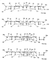
- Figure 4(a) represents the configuration in which the print table 27 is supporting a workpiece W in the raised, printing position, and the walking beams 95, 135 of the input and output transfer units 85, 125 are each in the lowered, outer positions out of engagement with workpieces W, with the input walking beam 95 being located at the loading station 38a and the input transfer station 81 and the output walking beam 135 being located at the unloading station 39a and the output transfer station 121.
- the workpiece W is fully supported by the print table 27 and held thereto by the application of vacuum to the vacuum section 28 thereof.
- the vacuum is released from the vacuum section 28 of the print table 27, and, as illustrated in Figure 4(b) , the print table 27 is lowered to the lowered, loading/unloading position.
- the resilient elements 30 of each of the workpiece support elements 29 are brought into engagement with respective ones of the stops 31, which acts to cause biasing, here compression, of the resilient elements 30, which causes the support elements 29 to extend above the upper surface of the print table 27, such as to support the workpiece W thereon in a loading/unloading position in which the workpiece W is spaced from the upper surface of the print table 27.
- the output transfer unit 125 is then operated, in this embodiment by actuating the horizontal drive mechanism 141 thereof, such as to move the output walking beam 135 horizontally inwardly to be located beneath workpieces W located on respective ones of the print station and the output transfer station 121.
- the input and output walking beams 95, 135 are then each raised to the raised positions, in this embodiment by operating the respective lifting mechanisms 97, 137, here simultaneously, which acts to lift the workpieces W located thereabove from the supporting structures, namely, the loading station 38a, the input transfer station 81, the print station and the output transfer station 121.
- a vacuum is applied to the vacuum sections 103, 104, 143, 144 of the walking beams 95, 135, such that the workpieces W are held thereto.
- the input and output transfer units 85, 125 are then operated to move the walking beams 95, 135 thereof horizontally, in this embodiment by operation of the respective horizontal drive mechanisms 101, 141, here simultaneously, with the output walking beam 135 being moved outwardly, such that the workpieces W located at the print station and the output transfer station 121 are moved respectively to the output transfer station 121 and the unloading station 39a, and with the input walking beam 95 being moved inwardly, such that the workpieces W located at the input transfer station 81 and the loading station 38a are moved respectively to the print station and the input transfer station 81.
- the vacuum is released from the vacuum sections 103, 104, 143, 144 of the walking beams 95, 135.
- the input and output walking beams 95, 135 are then each lowered to the lowered positions, in this embodiment by operating the respective lifting mechanisms 97, 137, here simultaneously, which acts to lower the supported workpieces W onto the supporting structures therebelow, namely, the input transfer station 81, the print station, the output transfer station 121 and the unloading station 39a.
- the input walking beam 95 is moved horizontally outwardly, in this embodiment by operation of the respective horizontal drive mechanism 101, such that the input walking beam 95 is located adjacent to loading station 38a and the input transfer station 81, as illustrated in Figure 4(g) .
- This procedure can then be repeated in the same manner for subsequent workpieces W.
- the input transfer unit 85 is still operated to transfer a workpiece W from the input transfer station 81 to the printing station.
- the input and output transfer units 85, 125 are operated simultaneously, but in another embodiment can be operated independently.
- each of the print modules 3a, 3b, 3c cycle synchronously. If, however, any of the print modules 3a, 3b, 3c is unable to print workpieces W, the input and output feed assemblies 38, 39 of the non-printing print modules 3a, 3b, 3c still function, so that workpieces W can still be fed to and from other of the print modules 3a, 3b, 3c.
- This configuration results in only a proportional reduction in throughput in the event of a fault to one or more of the print modules 3a, 3b, 3c, because, rather than requiring complete closure of the line, the screen printing system of the present invention allows for continued operation of the functioning print modules 3a, 3b, 3c, thereby providing for an overall increase in the uptime of the line.
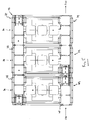
- Figure 5 illustrates a workpiece-processing system in accordance with a second embodiment of the present invention.
- the workpiece-processing system of this embodiment differs from that of the above-described workpiece-processing system in that at least one of the workpiece-processing modules 3a, 3b, 3c, in this embodiment the first workpiece-processing module 3a, provides a different workpiece-processing function to the other workpiece-processing modules 3b, 3c, whereby load balancing can be achieved between the different workpiece-processing modules 3a, 3b, 3c.
- the workpiece-processing system comprises a ball-placement machine
- the first workpiece-processing module 3a comprises a printing module
- the workpiece-processing unit 11 comprises a print unit which is operable to print deposits of a print medium onto workpieces W, here of flux
- the second and third workpiece-processing modules 3b, 3c each comprise ball placement modules
- the workpiece-processing units 11 comprise ball placement units, such as disclosed in WO-A-2000/054921 , which are operable to place balls, here solder balls, on the printed deposits on respective ones of the workpieces W.
- workpieces W are fed (F in ) to the first workpiece-processing module 3a along one, the second, feed assembly 39 and printed thereby, and then the printed workpieces W are selectively fed by operation of the other, first, feed assemblies 38 of the workpiece-processing modules 3a, 3b, 3c to ones of the second and third workpiece-processing modules 3b, 3c to place balls on the printed deposits on respective ones of the workpieces W, and subsequently fed (F out ) downstream by the one, second, feed assemblies 39 of the second and third workpiece-processing modules 3b, 3c, typically to a re-flow oven to melt the balls and form connection bumps on the workpieces W.
- the loading of the first workpiece-processing module 3a is balanced to the loading of the second and third workpiece-processing modules 3b, 3c, as ball placement modules, in that a printer can typically keep pace with two or more ball placers, thereby maximizing the throughput of the workpiece-processing system.
- the present invention has application to workpiece-processing modules 3 of any kind and in any number, and allows for active re-configuration of the processing paths of workpieces W, for example, where workpiece-processing modules 3 go off line.
- This active re-configuration of the workpiece pathways is particularly effective where the workpiece-processing system includes multiple ones of each kind of workpiece-processing module 3.
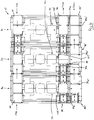
- Figure 6 illustrates a workpiece-processing system in accordance with a third embodiment of the present invention.
- the workpiece-processing system of this embodiment differs from that of the above-described first embodiment in that the feed unit 37 comprises first and second rear feed assemblies 39, 39', which together provide first and second output lines, which provide first and second workpiece feeds F1 out , F2 out , such as for dual lane production, with the output transfer units 125 of the workpiece-processing modules 3a, 3b, 3c each being modified to transfer workpieces W from the print station to the output transfer station 121, from the output transfer station 121 to the unloading station 39a of the first, inner rear feed assembly 39 and from the unloading station 39a of the first, inner rear feed assembly 39 to the unloading station 39a' of the second, outer rear feed assembly 39'.
- the output transfer units 125 of the workpiece-processing modules 3a, 3b, 3c are operated selectively to provide workpieces W to the first and second rear feed assemblies 39, 39' thereof, in dependence upon the requirements of the first and second workpiece feeds F1 out , F2 out .
- the output transfer units 125 of the first and second workpiece-processing modules 3a, 3b are operated to provide workpieces W to the second, outer rear feed assemblies 39' thereof, and the third workpiece-processing module 3c is operated to provide workpieces W to the first, inner rear feed assembly 39 thereof.
- the workpiece-processing system of this embodiment also differs from that of the above-described first embodiment in that two input workpiece feeds F1 in , F2 in are provided to the feed unit 37.
- the workpieces W in the respective ones of the input workpiece feeds F1 in , F2 in are different, but in another embodiment could be the same.
- separate input workpiece feeds F1 in , F2 in are provided to ones of the workpiece-processing modules 3a, 3b, 3c.
- the input work piece feeds F1 in , F2 in are provided respectively to the third workpiece-processing module 3c and the first and second workpiece-processing modules 3a, 3b, with the first input workpiece feed F1 in being supplied to the front feed assembly 38 of the third workpiece-processing module 3c and the second input workpiece feed F2 in being supplied to the front feed assembly 38 of the first workpiece-processing module 3a and the front feed assembly 38 of the second workpiece-processing module 3b by selective operation of the front feed assemblies 38 of the first and second workpiece-processing modules 3a, 3b.
- the workpiece-processing modules 3a, 3b, 3c can provide for different operations on the workpieces W, such as different printing operations.
- first and second workpiece-processing modules 3a, 3b provide for the same operation on the workpieces W, here the same printing operation
- third workpiece-processing module 3c provides for a different printing operation to the first and second workpiece-processing modules 3a, 3b.
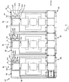
- Figure 7 illustrates a workpiece-processing system in accordance with a fourth embodiment of the present invention.
- the workpiece-processing system of this embodiment differs from that of the above-described first embodiment in that the front feed assembly 38 of the feed unit 37 of each workpiece-processing module 3a, 3b, 3c comprises a separate cassette feed mechanism 201.
- the cassette feed mechanism 201 comprises a cassette 203 which holds a plurality of workpieces W, which can be individually removed therefrom.
- the cassette 203 includes a plurality of individual slots in which the workpieces W are stacked.
- the cassette 203 is supported by linear bearings 204, which act to fix the lateral position of the cassette 203 and provide only for vertical movement of the cassette 203.
- the cassette feed mechanism 201 further comprises a drive unit 205, in this embodiment an elevator platform, which is operative to move the cassette 203 vertically between predetermined positions, such that the cassette 203 provides an upline buffer station which buffers a workpiece W for transfer downstream by the input transfer station 81, which is operative to withdraw the buffered workpiece W from the cassette 203.
- the cassette 203 in operation, is raised to a maximum height and successively lowered, such that a successive one of the workpieces W is presented to the input transfer station 81.
- the drive unit 205 comprises a leadscrew 207 which is coupled to the cassette 203, and an actuator 209, here a motor and associated gearbox assembly, which is operative to drive the leadscrew 207 to move the cassette 203 between the predetermined positions, such that a workpiece W is successively buffered to the input transfer station 81.
- the rear feed assemblies 39 of the workpiece-processing modules 3a, 3b, 3c provide a single, common output workpiece feed F out .
- FIGS 8 and 9 illustrate a workpiece-processing system in accordance with a fifth embodiment of the present invention.
- the workpiece-processing system of this embodiment differs from that of the above-described first embodiment in that the workpiece-processing system is configured for holt-melt printing onto wafers, in this embodiment solar cell wafers, as the workpieces W.
- the workpiece-processing units 11, as print units, of the first and second workpiece-processing modules 3a, 3b are configured for holt-melt printing onto wafers. Specifically, in each of the first and second workpiece-processing modules 3a, 3b, the printing screen PS, the print head 19, here squeegees, and the print table 27 are heated, here to a temperature between 60 and 100 C.
- the workpiece-processing system of this embodiment further differs from that of the above-described first embodiment in comprising an inverting device 301 for inverting workpieces W to provide for printing on both lower and upper sides of the workpieces W.
- the inverting device 301 is located between ones of feed assemblies 38, 39 of adjacent workpiece-processing modules 3a, 3b, 3c, here the rear feed assemblies 39 of the first and second workpiece-processing modules 3a, 3b.
- This configuration with the workpiece-processing modules 3a, 3b, 3c being configured in series, advantageously provides for hot-melt printing of wafers with a printing machine which has a footprint of a similar size to a conventional printing machine. It will be understood, however, that the inverting device 301 can be alternatively located.
- the inverting device 301 comprises a flipper, as a rotatable element 303, here in the form of wheel, which includes at least one pair of oppositely-directed slots 305 for receiving workpieces W therein.
- the rotatable element 303 is configured such that a slot 305, when located at the downline buffer sub-feed assembly 39c of the rear feed assembly 39 of the first workpiece-processing module 3a, receives a workpiece W therein by operation of the rear feed assembly 39 of the first workpiece-processing module 3a, and, by rotation of the rotatable element 303, such that a slot 305, when located at the upline buffer sub-feed assembly 39b of the rear feed assembly 39 of the second workpiece-processing module 3b, presents a workpiece W in an inverted orient to be fed by operation of the rear feed assembly 39 of the second workpiece-processing module 3b.
- the feed assemblies 39 of the first and second workpiece-processing modules 3a, 3b can operate simultaneously on two workpieces W.
- the rotatable element 303 includes a plurality of pairs of oppositely-directed slots 305, which allows for workpieces W to be buffered on the rotatable element 303.
- the workpiece-processing system as a solar cell printing machine, provides for the printing of contact fingers on solar cells.
- an input workpiece feed F in is fed to the front feed assembly 38 of the first workpiece-processing module 3a, which is operative to print a fine silver collector array on the upper surface of a workpiece W using a silver paste having a first melting point, here towards the upper end of the mentioned range.
- the printed workpiece W is then transferred to the rear feed assembly 39 of the first workpiece-processing module 3a, by which time the print will have dried sufficiently to allow for handling.
- a first printed workpiece W is transferred by the rear feed assembly 39 to the inverting device 301, in this embodiment being located in a slot 305 in the rotatable element 303, and the rotatable element 303 is rotated to present a workpiece W in an inverted orient to the rear feed assembly 39 of the second workpiece-processing module 3b.
- a first printed and inverted workpiece W is then printed by the second workpiece-processing module 3b, which is operative to print bus bars on the other, lower surface of a workpiece W using a silver-aluminum compound having a second melting point, lower than the melting point of the silver paste.
- a second printed workpiece W is transferred by the front feed assemblies 38 of the second and third workpiece-processing modules 3b, 3c to the third workpiece-processing module 3c.
- a second printed workpiece W is then printed by the third workpiece-processing module 3c, which is operative to print a back side field on the other, lower surface of a workpiece W using an aluminum compound.
- a third printed workpiece W is then transferred downstream by the rear feed assembly 39 of the third workpiece-processing module 3c, here in an output workpiece feed F out directly to a firing furnace.
- the present invention has application in relation to any workpiece-processing modules, including ball placement modules and pick-and-place modules.
Landscapes
- Engineering & Computer Science (AREA)
- Manufacturing & Machinery (AREA)
- Microelectronics & Electronic Packaging (AREA)
- Mechanical Engineering (AREA)
- Screen Printers (AREA)
- Manufacturing Of Printed Wiring (AREA)
- Printing Methods (AREA)
- Electric Connection Of Electric Components To Printed Circuits (AREA)
- Container, Conveyance, Adherence, Positioning, Of Wafer (AREA)
- Specific Conveyance Elements (AREA)
Description
- The present invention relates to a wafer processing system for and method of processing wafers, including solar cell wafers, and in particular a screen printing system for and method of printing wafers. The general drive in the electronics industry towards complex multi-layer substrates, greater component population on substrates and increased interconnectivity within substrates creates greater demands on the processing operations, in particular the printing operation, both in terms of accuracy and throughput.
- SMT manufacturing comprises three basic processes, namely, printing of material deposits on a substrate, including printing of solder deposits, placement of components on the printed substrate and re-flow of the printed deposits.
- The manufacturing equipment comprises machines in an in-line configuration, which are interconnected by conveyors which pass through the machines, with the substrates first passing to a printing machine for the printing of material deposits, then to a pick-and-place machine at which components are placed on the printed substrate, and finally a re-flow machine where the assembly is rendered homogeneous.
- Recent developments to increase throughput and satisfy the increasing demands in productivity have been to increase the output of the various machines. This has been achieved by shortening the time of each of the machine operations and the time between operations, and also providing multiple tracks through the machines. In such multiple-track printing machines, the printing screen includes a plurality of images, one for each track, which allow patterns of deposit to be printed simultaneously on multiple substrates in a single printing operation.
- Whilst such multi-track printing machines have provided for increased throughput, there is a limit to the increase in throughput which is possible, given the sequential processing of the workpieces in using a single printing screen.
- Solar cell manufacturing requires the printing of images on the upper and lower sides of wafers, and the subsequent firing of the printed wafers. Typically, one image is printed on the upper side of a wafer and two images are printed on the underside of a wafer.
- For such processing, a conventional production line includes nine separate processing machines, these being a wafer loader for loading wafers onto the production line, a first printer for printing a first print onto one side of a wafer, a first dryer for drying the printed wafer, a flipper for inverting the wafer, a second printer for printing a second print onto the other side of the wafer, a second dryer for drying the printed wafer, a third printer for printing a third print onto the other side of the wafer, a firing furnace for firing the printed wafer and an unloader for unloading finished wafers from the production line. Not only are a large number of separate machines are required, but these require a large area.
- Recently, a hot-melt printing process has been developed for the printing of contact fingers on solar cell wafers, which eliminates the need for the drying operations. The use of hot-melt printing reduces the number of separate machines to seven, in not requiring the conventional dryers, but still a large number of machines are required, which require a large area.
-
US-A-5906158 discloses a screen printing apparatus, a feed-in unit which provides substrates individually to the screen printing apparatus and a feed-out unit which removes substrates individually from the screen printing apparatus following a printing operation. -
US-A-5730051 discloses a screen printing machine having a carry-in conveyor, a carry-out conveyor and a positioning stage arranged therebetween, over which an object is successively transferred. -
US-A-2004/0247417 discloses an intermediate product transferring apparatus for transferring an intermediate product between a single-wafer carrying line for carrying the intermediate product in a single-wafer manner and a manufacturing apparatus for manufacturing the intermediate product. - It is an aim of the present invention to provide a workpiece processing system and method, in particular a workpiece printing system and method, which allows for a high throughput of workpieces.
- It is another aim of the present invention to provide a workpiece processing system and method, in particular a workpiece printing system and method, which comprises a plurality of workpiece-processing modules and provides for versatility in configuring the processing paths for the workpieces, such as in balancing the loads of workpiece-processing modules where the workpiece-processing modules provide for different kinds of workpiece processing, for example, printing and ball-placement, and, where more than one output line is supplied with workpieces, providing workpieces in different numbers to respective output lines.
- It is also a particular aim of the present invention to provide a workpiece printing system and method, which provides for the printing of wafers, in particular solar cell wafers, by a single machine that is of a size similar to a conventional printer, thereby considerably reducing the space required for production.
- In one aspect the present invention provides a wafer processing system, characterized by a plurality of wafer processing modules which are disposed in parallel relation and each separably operable to process wafers, each comprising a wafer processing unit for processing wafers and a feed unit for transferring wafers to and from the wafer processing unit, wherein the feed unit comprises input and output feed assemblies for transferring wafers to and from the wafer processing unit which provides a wafer processing station and a processing zone feed assembly which interconnects the input and output feed assemblies for transferring wafers from the input feed assembly to the wafer processing unit and from the wafer processing unit to the output feed assembly, and the output feed assemblies together provide at least one common output feed along which wafers are transferred.
- In a further aspect the present invention provides a method of processing wafers, characterized by the steps of: providing a plurality of wafer processing modules which are disposed in parallel relation and each separably operable to process wafers, each wafer processing module comprising a wafer processing unit for processing wafers and a feed unit for transferring wafers to and from the wafer processing unit, wherein the feed unit comprises input and output feed assemblies for transferring wafers to and from the wafer processing unit which provides a wafer processing station and a processing zone feed assembly which interconnects the input and output feed assemblies for transferring wafers from the input feed assembly to the wafer processing unit and from the wafer processing unit to the output feed assembly, and the output feed assemblies together provide at least one common output feed along which wafers are transferred; and transferring wafers to and from the wafer processing units and along the at least one common output feed.
- Preferred embodiments of the present invention will now be described hereinbelow by way of example only with reference to the accompanying drawings, in which:
-
Figure 1 illustrates a perspective view of a screen printing system in accordance with a first embodiment of the present invention; -
Figure 2 illustrates an enlarged perspective view of one print module of the screen printing system ofFigure 1 , with the print unit removed for ease of reference; -
Figure 3 illustrates a part-sectional longitudinal view (along section I-I) through the print module ofFigure 2 ; -
Figures 4(a) to (g) schematically represent the operation of one print module of the screen printing system ofFigure 1 ; -
Figure 5 illustrates a plan view of a screen printing system in accordance with a second embodiment of the present invention; -
Figure 6 illustrates a plan view of a screen printing system in accordance with a third embodiment of the present invention; -
Figure 7 illustrates a plan view of a screen printing system in accordance with a fourth embodiment of the present invention; -
Figure 8 illustrates a perspective view of a screen printing system in accordance with a fifth embodiment of the present invention; and -
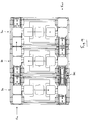
Figure 9 illustrates a plan view of the screen printing system ofFigure 8 . -
Figures 1 to 4 illustrate a workpiece-processing system, in this embodiment a screen printing system, in accordance with a first embodiment of the present invention. - The screen printing system comprises at least one workpiece-processing module, in this embodiment a plurality of workpiece-
processing modules - Each
print module support unit 5, which comprises a lower,base support member 7, in this embodiment a frame member, which rests on the ground, and anupper support member 9, in this embodiment a frame member, which is mounted on thelower support member 7. - In this embodiment the
lower support members 7 of theprint modules lower support members 7 of theprint modules - In this embodiment the
upper support members 9 of theprint modules - Each
print module processing unit 11, in this embodiment a print unit, which is mounted to theupper support member 9 and operable to print deposits of a print medium onto successive workpieces W. - The
print unit 11 comprises ascreen support member 15 for supporting a printing screen PS, aprint head 19 which is movable over the printing screen PS to print deposits of a print medium through a pattern of apertures in the printing screen PS and onto a workpiece W supported therebelow, and adrive mechanism 21 for driving theprint head 19 over the printing screen PS in a printing operation. - In this embodiment the
print head 19 is an enclosed print head, which is driveable in a reciprocating manner over the printing screen PS, such as to print in each of the opposite directions of movement. In alternative embodiments theprint head 19 could be of any other suitable design, such as a squeegee, and could be operable such as to print in only one direction of movement. - As particularly illustrated in
Figures 2 and3 , eachprint module workpiece support assembly 22 which receives a workpiece W and supports the same beneath the printing screen PS. - The
workpiece support assembly 22 comprises aworkpiece support unit 23 which supports a workpiece W, and analignment mechanism 24 for aligning a supported workpiece W relative to the printing screen PS. - The
workpiece support unit 23 comprises aworkpiece support member 25, which is movable vertically and provides a print station, and alifting mechanism 26, which is operable to raise and lower theworkpiece support member 25. - In this embodiment the
workpiece support member 25 is movable between a first, lowered, loading position, in which theworkpiece support member 25 can be loaded with a workpiece W and a second, raised, workpiece-processing, here printing position, in which the workpiece W is set at a position beneath the printing screen PS for printing. The printing system of the present invention allows for both on-contact and off-contact printing. - In this embodiment the
workpiece support member 25 comprises a workpiece-processing table 27, here a print table, in this embodiment in the form of a platen, which includes avacuum section 28, here centrally located, which is operative to hold a workpiece W thereto. - In this embodiment the
vacuum section 28 comprises a pad, here a sintered plate, typically a sintered ceramic plate, which is set in the print table 27, such as to define a planar upper surface, and provides for a vacuum at the upper surface thereof on application of a vacuum source to the lower surface thereof. - In this embodiment the
workpiece support member 25 further comprises a plurality ofworkpiece support elements 29, here upstanding pillars, which extend through the print table 27 and are biased downwardly byresilient elements 30, here compression springs. - In this embodiment the
resilient elements 30 are configured to act againstrespective stops 31, such that, when the print table 27 is in the lowered, loading position, theresilient elements 30 are compressed and theworkpiece support elements 29 project above the upper surface of the print table 27, such as to receive a workpiece W thereon in spaced relation from the upper surface of the print table 27, and, when the print table 27 is in the raised, printing position, theworkpiece support elements 29 are at or below the upper surface of the print table 27, here flush to the upper surface of the print table 27, whereby the lower surface of the workpiece W is fully supported by the upper surface of the print table 27. - In this embodiment the print table 27 includes at least one, here a plurality of
windows 32, which allow for a line of sight to edges of a supported workpiece W and alignment marks, often referred to as fiducials, on the lower surface of the printing screen PS. - In this embodiment the
lifting mechanism 26 comprises aleadscrew 33, which is threadably coupled to the print table 27, such that rotation of theleadscrew 33 in the opposite, clockwise and counter-clockwise senses causes a respective one of the raising or lowering of the print table 27, and anactuator 34 for rotating theleadscrew 33. - In this embodiment the
actuator 34 comprises a drive motor and an associated gearbox assembly. - In this embodiment the
alignment mechanism 24 comprises at least one, in this embodiment a plurality ofcamera units 35, which are configured such as to view edges of a supported workpiece W and the alignment marks on the lower surface of the printing screen PS through respective ones of thewindows 32 in the print table 27, and anactuator unit 36 which includes a plurality of actuators, here drive motors, which are operable, in response to the images as acquired by thecamera units 35, to correct any misalignment in the supported workpiece W relative to the printing screen PS. - In this embodiment the
actuator unit 36 comprises three actuators for positioning the workpiece W in X, Y and θ axes. In other embodiments theactuator unit 36 could comprise any number and arrangement of actuators which are such as to enable alignment of a supported workpiece W relative to the printing screen PS. - In this embodiment the workpiece W is moved in relation to the printing screen PS in order to achieve alignment of the workpiece W relative to the printing screen PS, but in another embodiment the printing screen PS could be moved in relation to the workpiece W in order to achieve alignment of the workpiece W relative to the printing screen PS.
- Each
print module feed unit 37 which is mounted to theupper support member 9 and operable to transfer workpieces W to and from theprint unit 11. - The
feed unit 37 comprises input andoutput feed assemblies print unit 11, which are operable to transfer workpieces W to and from theprint module zone feed assembly 40, which interconnects the input andoutput feed assemblies input feed assembly 38 to theworkpiece support member 25 of theworkpiece support unit 23 for printing and, following printing, from theworkpiece support member 25 of theworkpiece support unit 23 to theoutput feed assembly 39. - In this embodiment the input and
output feed assemblies - As particularly illustrated in
Figure 2 , theinput feed assembly 38 comprises first, second andthird sub-feed assemblies input feed assembly 38 being to maintain a workpiece W for transfer to the printzone feed assembly 40 and transfer workpieces W to anydownstream print modules - The first,
loading sub-feed assembly 38a provides a loading station from which a workpiece W can be loaded into theprint unit 11. - The second, upline
buffer sub-feed assembly 38b is upstream of theloading sub-feed assembly 38a and provides an upline buffer station which buffers a workpiece W for transfer downstream to theloading sub-feed assembly 38a. - The third, downline
buffer sub-feed assembly 38c is downstream of theloading sub-feed assembly 38a and provides a downline buffer station which buffers a workpiece W for transfer downstream. - Each of the
sub-feed assemblies drive elements actuator 45, in this embodiment a drive motor, which is commonly coupled, in this embodiment by apulley arrangement 47, to thedrive elements drive elements actuator 45. - In this embodiment the
inner drive element 41 of the first, loadingsub-feed assembly 38a is configured, here by an arrangement of pulleys, such as to comprise first and second spaced drive element sections, which accommodate awalking beam 95 therebetween, as will be described in more detail hereinbelow. - Each of the
sub-feed assemblies sensor unit 51 which comprises first andsecond sensors sensors actuator 45 drives thedrive elements upstream sensor 53, on detection of the leading edge of the workpiece W by thefirst sensor 53, theactuator 45 drives thedrive elements downstream sensor 55, theactuator 45 is stopped to position the workpiece W at the required position. - The
output feed assembly 39 comprises first, second and thirdsub-feed assemblies output feed assembly 39 being to receive workpieces W from the printzone feed assembly 40 and transfer the same downstream, as will be described in more detail hereinbelow. - The first, unloading
sub-feed assembly 39a provides an unloading station to which a workpiece W is unloaded from theprint unit 11. - The second, upline buffer
sub-feed assembly 39b is upstream of the unloadingsub-feed assembly 39a and provides an upline buffer station which buffers a workpiece W for transfer downstream. - The third, downline buffer
sub-feed assembly 39c is downstream of the unloadingsub-feed assembly 39a and provides a downline buffer station which buffers a workpiece W for transfer downstream. - Each of the
sub-feed assemblies drive elements actuator 65, in this embodiment a drive motor, which is commonly coupled, in this embodiment by apulley arrangement 67, to thedrive elements drive elements actuator 65. - In this embodiment the
inner drive element 61 of the first, unloadingsub-feed assembly 39a is configured, here by an arrangement of pulleys, such as to comprise first and second spaced drive element sections, which accommodate awalking beam 125 therebetween, as will be described in more detail hereinbelow. - Each of the
sub-feed assemblies sensor unit 71 which comprises first andsecond sensors sensors actuator 65 drives thedrive elements upstream sensor 73, on detection of the leading edge of the workpiece W by thefirst sensor 73, theactuator 65 drives thedrive elements downstream sensor 75, theactuator 65 is stopped to position the workpiece W at the required position. - As particularly illustrated in
Figures 2 and3 , the printzone feed assembly 40 comprises aninput transfer station 81, which is disposed adjacent, in this embodiment inwardly adjacent, theloading station 38a, and aninput transfer unit 85, which is operable to transfer workpieces W from theloading station 38a to theinput transfer station 81 and from theinput transfer station 81 to the printing station. - In this embodiment the
input transfer station 81 comprises a plurality ofworkpiece support elements 87, here four fixed, upstanding pillars which are arranged in the form of a square. In alternative embodiments any number and configuration ofworkpiece support elements 87 could be utilized which support the workpieces W. - In this embodiment the
input transfer unit 85 is operable to transfer a first workpiece W from theloading station 38a to theinput transfer station 81 and a second workpiece W from theinput transfer station 81 to the print station, and in this embodiment theinput transfer unit 85 is configured such as to transfer the first and second workpieces W simultaneously. - In this embodiment the
input transfer unit 85 is a walking-beam assembly, which comprises a fixed,main support 91, amovable body 93 which is movable relative to themain support 91 and includes a horizontal, walkingbeam 95, in this embodiment at an upper surface of themovable body 93, alifting mechanism 97 for raising and lowering themovable body 93, and adrive mechanism 101 for moving themovable support 93 horizontally. - In this embodiment the
movable body 93 is supported on themain support 91 by bearings, which allow for vertical and horizontal sliding of themovable body 93 relative to themain support 91. - In this embodiment the
walking beam 95 includes first andsecond vacuum sections - In this embodiment the
vacuum sections walking beam 95 and provide for a vacuum thereat on application of a vacuum source thereto. - In this embodiment the
lifting mechanism 97 is a cam mechanism which comprises acam 105 and anactuator 107, in this embodiment a drive motor, which is operable to drive thecam 105 between a first, lowered position in which themovable body 93 is in a first, lowered position, in which position thewalking beam 95 is dis-engaged from workpieces W located thereabove, and a second, raised position in which themovable body 93 is in a second, raised position in which thewalking beam 95 supports workpieces W located thereabove. - In this embodiment the
cam 105 comprises a pair ofcam rollers movable body 93 and a pair ofcam members cam rollers main support 91 and are rotatable by theactuator 107 between the first and second positions. - In this embodiment the
drive mechanism 101 is a linear motor, which is operative to move themovable body 93, and hence thewalking beam 95, between a first, outer position in which thewalking beam 95 extends across theloading station 38a and theinput transfer station 81 and a second, inner position in which thewalking beam 95 extends across theinput transfer station 81 and the print station. - With this configuration, the
walking beam 95, when in the outer position, can be raised by operation of theactuator 107, to lift workpieces W from theloading station 38a and theinput transfer station 81, moved horizontally to the inner position by thedrive mechanism 101 so as to position the workpieces W over respective ones of theinput transfer station 81 and the print station, and then lowered, by operation of theactuator 107, to lower the workpieces W onto theinput transfer station 81 and the print station. - In an alternative embodiment the
input transfer unit 85 could comprise a belt-feed assembly. The walking-beam assembly has the particular advantage of supporting delicate workpieces W, such as substrates used for solar cells and fuel cells which are prone to breaking, particularly in the printing operation. - As particularly illustrated in
Figures 2 and3 , the printzone feed assembly 40 further comprises anoutput transfer station 121, which is disposed adjacent, in this embodiment inwardly adjacent, the unloadingstation 39a, and anoutput transfer unit 125, which is operable to transfer workpieces W from the print station to theoutput transfer station 121 and from theoutput transfer station 121 to the unloadingstation 39a. - In this embodiment the
output transfer station 121 comprises a plurality ofworkpiece support elements 127, here four fixed, upstanding pillars which are arranged in the form of a square. In alternative embodiments any number and configuration ofworkpiece support elements 127 could be utilized which support the workpieces W. - In this embodiment the
output transfer unit 125 is operable to transfer a first workpiece W from the print station to theoutput transfer station 121 and a second workpiece W from theoutput transfer station 121 to the unloadingstation 39a, and in this embodiment theoutput transfer unit 125 is configured such as to transfer the first and second workpieces W simultaneously. - In this embodiment the
output transfer unit 125 is a walking-beam assembly, which comprises a fixed,main support 131, amovable body 133 which is movable relative to themain support 131 and includes a horizontal,walking beam 135, in this embodiment at an upper surface of themovable body 133, alifting mechanism 137 for raising and lowering themovable body 133, and ahorizontal drive mechanism 141 for moving themovable support 133 horizontally. - In this embodiment the
movable body 133 is supported on themain support 131 by bearings, which allow for vertical and horizontal sliding of themovable body 133 relative to themain support 131. - In this embodiment the
walking beam 135 includes first andsecond vacuum sections - In this embodiment the
vacuum sections walking beam 135 and provide for a vacuum thereat on application of a vacuum source thereto. - In this embodiment the
lifting mechanism 137 is a cam mechanism which comprises acam 145 and anactuator 147, in this embodiment a drive motor, which is operable to drive thecam 145 between a first, lowered position in which themovable body 133 is in a first, lowered position, in which position thewalking beam 135 is dis-engaged from workpieces W located thereabove, and a second, raised position in which themovable body 133 is in a second, raised position, in which position thewalking beam 135 supports workpieces W located thereabove. - In this embodiment the
cam 145 comprises a pair ofcam rollers movable support body 133 and a pair ofcam members main support 131, which engage respective ones of the pair ofcam rollers actuator 147 between the first and second positions. - In this embodiment the
drive mechanism 141 is a linear motor, which is operative to move themovable body 133, and hence thewalking beam 135, between a first, inner position in which thewalking beam 135 extends across the print station and theoutput transfer station 121 and a second, outer position in which thewalking beam 135 extends across theoutput transfer station 121 and the unloadingstation 39a. - With this configuration, the
walking beam 135, when in the inner position, can be raised by operation of theactuator 147, to lift workpieces W from the print station and theoutput transfer station 121, moved horizontally to the outer position by thedrive mechanism 141 so as to position the workpieces W over respective ones of theoutput transfer station 121 and the unloadingstation 39a, and then lowered, by operation of theactuator 147, to lower the workpieces W onto theoutput transfer station 121 and the unloadingstation 39a. - Each
print module controller 151 for controlling operation of theprint module other print modules - Operation of the above-described screen printing system will now be described hereinbelow with reference to
Figures 4(a) to (g) of the accompanying drawings. - In operation of the screen printing system, the input and
output feed assemblies - When the
input walking beam 95 is in the lowered, outer position or the inner position, as illustrated inFigures 4(a) to (c) and 4(e) to (g) , theinput feed assembly 38 is continually operated such as to maintain a supply of workpieces W to anydownstream print modules loading station 38a on commencement of the loading cycle of the print station, as illustrated inFigure 4(d) . - When the
output walking beam 135 is in the lowered, outer position or the inner position, as illustrated inFigures 4(a) to (d), (f) and (g) , theoutput feed assembly 39 is continually operated such as to transfer workpieces W downstream, and also to ensure that the unloadingstation 39a is free to receive a workpiece W from theoutput transfer station 121 on commencement of the unloading cycle of the print station, as illustrated inFigure 4(e) . -
Figure 4(a) represents the configuration in which the print table 27 is supporting a workpiece W in the raised, printing position, and the walking beams 95, 135 of the input andoutput transfer units input walking beam 95 being located at theloading station 38a and theinput transfer station 81 and theoutput walking beam 135 being located at the unloadingstation 39a and theoutput transfer station 121. - In this configuration, the workpiece W is fully supported by the print table 27 and held thereto by the application of vacuum to the
vacuum section 28 thereof. - Following printing by the
print unit 11, the vacuum is released from thevacuum section 28 of the print table 27, and, as illustrated inFigure 4(b) , the print table 27 is lowered to the lowered, loading/unloading position. - In lowering the print table 27 to the lowered, loading/unloading position, the
resilient elements 30 of each of theworkpiece support elements 29 are brought into engagement with respective ones of thestops 31, which acts to cause biasing, here compression, of theresilient elements 30, which causes thesupport elements 29 to extend above the upper surface of the print table 27, such as to support the workpiece W thereon in a loading/unloading position in which the workpiece W is spaced from the upper surface of the print table 27. - As illustrated in
Figure 4(c) , theoutput transfer unit 125 is then operated, in this embodiment by actuating thehorizontal drive mechanism 141 thereof, such as to move theoutput walking beam 135 horizontally inwardly to be located beneath workpieces W located on respective ones of the print station and theoutput transfer station 121. - As illustrated in
Figure 4(d) , the input and output walking beams 95, 135 are then each raised to the raised positions, in this embodiment by operating therespective lifting mechanisms loading station 38a, theinput transfer station 81, the print station and theoutput transfer station 121. - In this configuration, a vacuum is applied to the
vacuum sections - As illustrated in
Figure 4(e) , the input andoutput transfer units horizontal drive mechanisms output walking beam 135 being moved outwardly, such that the workpieces W located at the print station and theoutput transfer station 121 are moved respectively to theoutput transfer station 121 and the unloadingstation 39a, and with theinput walking beam 95 being moved inwardly, such that the workpieces W located at theinput transfer station 81 and theloading station 38a are moved respectively to the print station and theinput transfer station 81. - When in this configuration, the vacuum is released from the
vacuum sections - As illustrated in
Figure 4(f) , the input and output walking beams 95, 135 are then each lowered to the lowered positions, in this embodiment by operating therespective lifting mechanisms input transfer station 81, the print station, theoutput transfer station 121 and the unloadingstation 39a. - Following lowering of the input and output walking beams 95, 135, the
input walking beam 95 is moved horizontally outwardly, in this embodiment by operation of the respectivehorizontal drive mechanism 101, such that theinput walking beam 95 is located adjacent toloading station 38a and theinput transfer station 81, as illustrated inFigure 4(g) . - This procedure can then be repeated in the same manner for subsequent workpieces W.
- In the event that there is no workpiece W on the
loading station 38a of theinput feed assembly 38 of any of theprint modules input transfer unit 85 is still operated to transfer a workpiece W from theinput transfer station 81 to the printing station. - In this embodiment the input and
output transfer units - In normal operation, each of the
print modules print modules output feed assemblies non-printing print modules print modules - This configuration results in only a proportional reduction in throughput in the event of a fault to one or more of the
print modules print modules -
Figure 5 illustrates a workpiece-processing system in accordance with a second embodiment of the present invention. - The workpiece-processing system of this embodiment is very similar to that of the above-described first embodiment, and thus, in order to avoid unnecessary duplication of description, only the differences will be described in detail, with like parts being designated by like reference signs.
- The workpiece-processing system of this embodiment differs from that of the above-described workpiece-processing system in that at least one of the workpiece-
processing modules module 3a, provides a different workpiece-processing function to the other workpiece-processing modules processing modules - In this embodiment the workpiece-processing system comprises a ball-placement machine, where the first workpiece-processing
module 3a comprises a printing module, as in the above-described embodiment, in which the workpiece-processingunit 11 comprises a print unit which is operable to print deposits of a print medium onto workpieces W, here of flux, and the second and third workpiece-processing modules units 11 comprise ball placement units, such as disclosed inWO-A-2000/054921 , which are operable to place balls, here solder balls, on the printed deposits on respective ones of the workpieces W. - As illustrated, workpieces W are fed (Fin) to the first workpiece-processing
module 3a along one, the second, feedassembly 39 and printed thereby, and then the printed workpieces W are selectively fed by operation of the other, first,feed assemblies 38 of the workpiece-processing modules processing modules feed assemblies 39 of the second and third workpiece-processing modules - With this configuration, the loading of the first workpiece-processing
module 3a, as a print module, is balanced to the loading of the second and third workpiece-processing modules - It will be understood that the present invention has application to workpiece-processing modules 3 of any kind and in any number, and allows for active re-configuration of the processing paths of workpieces W, for example, where workpiece-processing modules 3 go off line. This active re-configuration of the workpiece pathways is particularly effective where the workpiece-processing system includes multiple ones of each kind of workpiece-processing module 3.
-
Figure 6 illustrates a workpiece-processing system in accordance with a third embodiment of the present invention. - The workpiece-processing system of this embodiment is quite similar to that of the above-described first embodiment, and thus, in order to avoid unnecessary duplication of description, only the differences will be described in detail, with like parts being designated by like reference signs.
- The workpiece-processing system of this embodiment differs from that of the above-described first embodiment in that the
feed unit 37 comprises first and secondrear feed assemblies 39, 39', which together provide first and second output lines, which provide first and second workpiece feeds F1out, F2out, such as for dual lane production, with theoutput transfer units 125 of the workpiece-processing modules output transfer station 121, from theoutput transfer station 121 to the unloadingstation 39a of the first, innerrear feed assembly 39 and from the unloadingstation 39a of the first, innerrear feed assembly 39 to the unloadingstation 39a' of the second, outer rear feed assembly 39'. - In this embodiment the
output transfer units 125 of the workpiece-processing modules rear feed assemblies 39, 39' thereof, in dependence upon the requirements of the first and second workpiece feeds F1out, F2out. - In this embodiment the
output transfer units 125 of the first and second workpiece-processing modules module 3c is operated to provide workpieces W to the first, innerrear feed assembly 39 thereof. - The workpiece-processing system of this embodiment also differs from that of the above-described first embodiment in that two input workpiece feeds F1in, F2in are provided to the
feed unit 37. In this embodiment the workpieces W in the respective ones of the input workpiece feeds F1in, F2in are different, but in another embodiment could be the same. - In this embodiment separate input workpiece feeds F1in, F2in are provided to ones of the workpiece-
processing modules - In this embodiment the input work piece feeds F1in, F2in are provided respectively to the third workpiece-processing
module 3c and the first and second workpiece-processing modules front feed assembly 38 of the third workpiece-processingmodule 3c and the second input workpiece feed F2in being supplied to thefront feed assembly 38 of the first workpiece-processingmodule 3a and thefront feed assembly 38 of the second workpiece-processingmodule 3b by selective operation of thefront feed assemblies 38 of the first and second workpiece-processing modules - In one embodiment the workpiece-
processing modules - In this embodiment the first and second workpiece-
processing modules module 3c provides for a different printing operation to the first and second workpiece-processing modules -
Figure 7 illustrates a workpiece-processing system in accordance with a fourth embodiment of the present invention. - The workpiece-processing system of this embodiment is quite similar to that of the above-described first embodiment, and thus, in order to avoid unnecessary duplication of description, only the differences will be described in detail, with like parts being designated by like reference signs.
- The workpiece-processing system of this embodiment differs from that of the above-described first embodiment in that the
front feed assembly 38 of thefeed unit 37 of each workpiece-processingmodule cassette feed mechanism 201. - The
cassette feed mechanism 201 comprises acassette 203 which holds a plurality of workpieces W, which can be individually removed therefrom. In this embodiment thecassette 203 includes a plurality of individual slots in which the workpieces W are stacked. - In this embodiment the
cassette 203 is supported bylinear bearings 204, which act to fix the lateral position of thecassette 203 and provide only for vertical movement of thecassette 203. - The
cassette feed mechanism 201 further comprises adrive unit 205, in this embodiment an elevator platform, which is operative to move thecassette 203 vertically between predetermined positions, such that thecassette 203 provides an upline buffer station which buffers a workpiece W for transfer downstream by theinput transfer station 81, which is operative to withdraw the buffered workpiece W from thecassette 203. In this embodiment, in operation, thecassette 203 is raised to a maximum height and successively lowered, such that a successive one of the workpieces W is presented to theinput transfer station 81. - In this embodiment the
drive unit 205 comprises aleadscrew 207 which is coupled to thecassette 203, and anactuator 209, here a motor and associated gearbox assembly, which is operative to drive theleadscrew 207 to move thecassette 203 between the predetermined positions, such that a workpiece W is successively buffered to theinput transfer station 81. - In this embodiment the
rear feed assemblies 39 of the workpiece-processing modules -
Figures 8 and9 illustrate a workpiece-processing system in accordance with a fifth embodiment of the present invention. - The workpiece-processing system of this embodiment is quite similar to that of the above-described first embodiment, and thus, in order to avoid unnecessary duplication of description, only the differences will be described in detail, with like parts being designated by like reference signs.
- The workpiece-processing system of this embodiment differs from that of the above-described first embodiment in that the workpiece-processing system is configured for holt-melt printing onto wafers, in this embodiment solar cell wafers, as the workpieces W.
- In this embodiment the workpiece-processing
units 11, as print units, of the first and second workpiece-processing modules processing modules print head 19, here squeegees, and the print table 27 are heated, here to a temperature between 60 and 100 C. - The workpiece-processing system of this embodiment further differs from that of the above-described first embodiment in comprising an
inverting device 301 for inverting workpieces W to provide for printing on both lower and upper sides of the workpieces W. - In this embodiment the
inverting device 301 is located between ones offeed assemblies processing modules rear feed assemblies 39 of the first and second workpiece-processing modules processing modules inverting device 301 can be alternatively located. - In this embodiment the
inverting device 301 comprises a flipper, as arotatable element 303, here in the form of wheel, which includes at least one pair of oppositely-directedslots 305 for receiving workpieces W therein. Therotatable element 303 is configured such that aslot 305, when located at the downline buffersub-feed assembly 39c of therear feed assembly 39 of the first workpiece-processingmodule 3a, receives a workpiece W therein by operation of therear feed assembly 39 of the first workpiece-processingmodule 3a, and, by rotation of therotatable element 303, such that aslot 305, when located at the upline buffersub-feed assembly 39b of therear feed assembly 39 of the second workpiece-processingmodule 3b, presents a workpiece W in an inverted orient to be fed by operation of therear feed assembly 39 of the second workpiece-processingmodule 3b. - In this embodiment, by providing at least one pair of oppositely-directed
slots 305 in therotatable element 303, thefeed assemblies 39 of the first and second workpiece-processing modules - In this embodiment the
rotatable element 303 includes a plurality of pairs of oppositely-directedslots 305, which allows for workpieces W to be buffered on therotatable element 303. - In this embodiment the workpiece-processing system, as a solar cell printing machine, provides for the printing of contact fingers on solar cells.
- In a first step, an input workpiece feed Fin is fed to the
front feed assembly 38 of the first workpiece-processingmodule 3a, which is operative to print a fine silver collector array on the upper surface of a workpiece W using a silver paste having a first melting point, here towards the upper end of the mentioned range. - The printed workpiece W is then transferred to the
rear feed assembly 39 of the first workpiece-processingmodule 3a, by which time the print will have dried sufficiently to allow for handling. - A first printed workpiece W is transferred by the
rear feed assembly 39 to theinverting device 301, in this embodiment being located in aslot 305 in therotatable element 303, and therotatable element 303 is rotated to present a workpiece W in an inverted orient to therear feed assembly 39 of the second workpiece-processingmodule 3b. - A first printed and inverted workpiece W is then printed by the second workpiece-processing
module 3b, which is operative to print bus bars on the other, lower surface of a workpiece W using a silver-aluminum compound having a second melting point, lower than the melting point of the silver paste. - A second printed workpiece W is transferred by the
front feed assemblies 38 of the second and third workpiece-processing modules module 3c. - A second printed workpiece W is then printed by the third workpiece-processing
module 3c, which is operative to print a back side field on the other, lower surface of a workpiece W using an aluminum compound. - A third printed workpiece W is then transferred downstream by the
rear feed assembly 39 of the third workpiece-processingmodule 3c, here in an output workpiece feed Fout directly to a firing furnace. - Finally, it will be understood that the present invention has been described in its preferred embodiments and can be modified in many different ways without departing from the scope of the invention as defined by the appended claims.
- For example, although exemplified in relation to print modules 3, the present invention has application in relation to any workpiece-processing modules, including ball placement modules and pick-and-place modules.
Claims (16)
- A wafer processing system, characterized by a plurality of wafer processing modules (3a, 3b, 3c) which are disposed in parallel relation and each separably operable to process wafers (W), each comprising a wafer processing unit (11) for processing wafers (W) and a feed unit (37) for transferring wafers (W) to and from the wafer processing unit (11), wherein the feed unit (37) comprises input and output feed assemblies (38, 39) for transferring wafers (W) to and from the wafer processing unit (11) which provides a wafer processing station and a processing zone feed assembly (40) which interconnects the input and output feed assemblies (38, 39) for transferring wafers (W) from the input feed assembly (38) to the wafer processing unit (11) and from the wafer processing unit (11) to the output feed assembly (39), and the output feed assemblies (39) together provide at least one common output feed (Fout) along which wafers (W) are transferred.
- The system of claim 1, wherein:(i) the wafer processing modules (3a, 3b, 3c) comprise print modules (3a, 3b, 3c), optionally comprising a hot-melt processing system for printing on wafers (W), optionally comprising three print modules, wherein first and second of the print modules (3a, 3b) provide for hot-melt printing on wafers (W), and an inverting device (301) for inverting wafers (W) between the first and second print modules (3a, 3b), optionally the inverting device (301) comprises a rotatable element (303) which includes slots (305) for receiving wafers (W) therein; or(ii) at least one of the wafer processing modules (3a, 3b, 3c) has a different function, optionally at least one wafer processing module (3a, 3b, 3c) comprises a printer and at least one wafer processing module (3a, 3b, 3c) comprises a ball placer, optionally at least one wafer processing module (3a, 3b, 3c) comprises a printer and a plurality of wafer processing modules (3a, 3b, 3c) comprise ball placers.
- The system of claim 1 or 2, comprising an inverting device (301) for inverting wafers (W), whereby ones of the wafer processing modules (3a, 3b, 3c) provide for operation on different sides of the wafers (W).
- The system of any of claims 1 to 3, wherein (i) the input feed assembly (38) comprises a belt feed mechanism or a cassette feed mechanism, (ii) the output feed assembly (39) comprises a belt feed mechanism, (iii) the input feed assemblies (38) of the wafer processing modules (3a, 3b, 3c) are connected together and define at least one input feed (Fin; F1in, F2in), (iv) the system is configured such that at least one of the input and output feed assemblies (38, 39) of the wafer processing modules (3a, 3b, 3c) are operative to feed wafers (W) downstream in the event that one or more of the wafer processing modules (3a, 3b, 3c) are inoperative, (v) the system comprises a single input feed (Fin) or at least two input feeds (F1in, F2in), (vi) the system comprises a single output feed (Fin) or at least two output feeds (F1out, F2out), and/or (vii) the feed unit (37) comprises at least two output feed assemblies (39, 39').
- The system of claim 4, wherein the input feed assembly (38) comprises a plurality of sub-feed assemblies (38a, 38b, 38c) which are each individually operable, including a first, loading sub-feed assembly (38a) which provides a loading station from which a wafer (W) can be loaded into the wafer processing unit (11) and a second, upline buffer sub-feed assembly (38b) upstream of the loading sub-feed assembly (38a) which provides an upline buffer station which buffers a wafer (W) for transfer downstream to the loading sub-feed assembly (38a), optionally the input feed assembly (38) includes a third, downline buffer sub-feed assembly (38c) downstream of the loading sub-feed assembly (38a) which provides a downline buffer station which buffers a wafer (W) for transfer downstream, optionally each of the sub-feed assemblies (38a, 38b, 38c) comprises a pair of drive elements (41, 41) which are disposed in spaced parallel relation such as to engage the opposite, lower edges of a wafer (W), and an actuator (45) which is commonly coupled to the drive elements (41, 41), such that the drive elements (41, 41) are commonly driven by the actuator (45), optionally each of the sub-feed assemblies (38a, 38b, 38c) comprises a sensor unit (51) which comprises first and second sensors (53, 55) which are disposed in spaced relation in the input feed direction, with the sensors (53, 55) being configured such that the actuator (45) drives the drive elements (41, 41) at a first transfer speed until a leading edge of a wafer (W) is detected by the first, upstream sensor (53), on detection of the leading edge of the wafer (W) by the first sensor (53), the actuator (45) drives the drive elements (41, 41) at a second, slower speed, and, on detection of the leading edge of the wafer (55) by the second, downstream sensor (55), the actuator (45) is stopped to position the wafer (W) at a required position, optionally the input feed assembly (38) is continually/automatically operated such as to maintain a supply of wafers (W) to any downstream wafer processing modules (3a, 3b, 3c), and also ensure that a wafer (W) is located at the loading station on commencement of a loading cycle of the wafer processing station.
- The system of any of claims 1 to 5, wherein the output feed assembly (39) comprises a plurality of sub-feed assemblies (39a, 39b, 39c) which are individually operable, including a first, unloading sub-feed assembly (39a) which provides an unloading station to which a wafer (W) is unloaded from the wafer processing unit (11) and a second, upline buffer sub-feed assembly (39b) upstream of the unloading sub-feed assembly (39a) which provides an upline buffer station which buffers a wafer (W) for transfer downstream, optionally the output feed assembly (39) includes a third, downline buffer sub-feed assembly (39c) downstream of the unloading sub-feed assembly (39a) which provides a downline buffer station which buffers a wafer (W) for transfer downstream, optionally each of the sub-feed assemblies (39a, 39b, 39c) comprises a pair of drive elements (61, 61) which are disposed in spaced parallel relation such as to engage opposite, lower edges of a wafer (W), and an actuator (65) which is commonly coupled to the drive elements (61, 61), such that the drive elements (61, 61) are commonly driven by the actuator (65), optionally each of the sub-feed assemblies (39a, 39b, 39c) comprises a sensor unit (71) which comprises first and second sensors (73, 75) which are disposed in spaced relation in the output feed direction, with the sensors (73, 75) being configured such that the actuator (65) drives the drive elements (61, 61) at a first transfer speed until a leading edge of a wafer (W) is detected by the first, upstream sensor (73), on detection of the leading edge of the wafer (W) by the first sensor (73), the actuator (65) drives the drive elements (61, 61) at a second, slower speed, and, on detection of the leading edge of the wafer (W) by the second, downstream sensor (75), the actuator (65) is stopped to position the wafer (W) at a required position, optionally the output feed assembly (39) is continually/automatically operated such as to transfer wafers (W) downstream, and also ensure that that the unloading station is free to receive a wafer (W) on commencement of an unloading cycle of the wafer processing station.
- The system of any of claims 4 to 6, wherein the processing zone feed assembly (40) comprises an input transfer station (81), which is disposed adjacent the loading station (38a), and an input transfer unit (85) for transferring wafers (W) from the loading station (38a) to the wafer processing station, optionally the input transfer station (81) comprises a plurality of supporting elements (87) for supporting a wafer (W), optionally the input transfer unit (85) transfers a first wafer (W) from the loading station (38a) to the input transfer station (81) and a second wafer (W) from the input transfer station (81) to the wafer processing station, optionally the input transfer unit (85) is configured such as to transfer the first and second wafers (W) simultaneously.
- The system of claim 7, wherein the input transfer unit (85):(a) is a walking-beam assembly, which comprises a main support (91), a movable support body (93) which is movable relative to the main support (91) and includes an input walking beam (95), a lifting mechanism (97) for raising and lowering the movable support body (93), and a drive mechanism (101) for moving the movable support body (93) laterally, optionally the input walking beam (95) includes first and second vacuum sections (103, 104) for holding wafers (W) thereto by vacuum, optionally the lifting mechanism (97) is a cam mechanism which comprises a cam (105) and an actuator (107) for driving the cam (105) between a first, lowered configuration in which the movable support body (93) is in a first, lowered position, in which position the input walking beam (95) is dis-engaged from wafers (W) located thereabove, and a second, raised configuration in which the movable support body (93) is in a second, raised position, in which position the input walking beam (95) supports wafers (W) located thereabove; or(b) comprises a belt-feed assembly.
- The system of claim 7 or 8, wherein the processing zone feed assembly (40) comprises an output transfer station (121) which is disposed adjacent the unloading station (39a), and an output transfer unit (125) for transferring wafers (W) from the wafer processing station to the output transfer station (121) and the output transfer station (121) to the unloading station (39a) of the at least one common output feed (Fout), optionally the output transfer station (121) comprises a plurality of supporting elements (127) for supporting a wafer (W), optionally the output transfer unit (125) transfers a first wafer (W) from the wafer processing station to the output transfer station (121) and a second wafer (W) from the output transfer station (121) to the unloading station (39a) of the at least one common output feed (Fout), optionally the output transfer unit (125) is configured such as to transfer the first and second wafers (W) simultaneously.
- The system of claim 9, wherein the output transfer unit (125):(a) is a walking-beam assembly which comprises a main support (131), a movable support body (133) which is movable relative to the main support (131) and includes an output walking beam (135), a lifting mechanism (137) for raising and lowering the movable support body (133), and a drive mechanism (141) for moving the movable support body (133) laterally, optionally the output walking beam (135) includes first and second vacuum sections (143, 144) for holding wafers (W) thereto by vacuum, optionally the lifting mechanism (137) is a cam mechanism which comprises a cam (145) and an actuator (147) for driving the cam (145) between a first, lowered configuration in which the movable support body (133) is in a first, lowered position, in which position the output walking beam (135) is dis-engaged from wafers (W) located thereabove, and a second, raised configuration in which the movable support body (133) is in a second, raised position, in which position the output walking beam (135) supports wafers (W) located thereabove; or(b) comprises a belt-feed assembly.
- A method of processing wafers (W), characterized by the steps of:providing a plurality of wafer processing modules (3a, 3b, 3c) which are disposed in parallel relation and each separably operable to process wafers (W), each wafer processing module (3a, 3b, 3c) comprising a wafer processing unit for processing wafers (W) and a feed unit (37) for transferring wafers (W) to and from the wafer processing unit (11), wherein the feed unit (37) comprises input and output feed assemblies (38, 39) for transferring wafers (W) to and from the wafer processing unit (11) which provides a wafer processing station and a processing zone feed assembly (40) which interconnects the input and output feed assemblies (38, 39) for transferring wafers (W) from the input feed assembly (38) to the wafer processing unit (11) and from the wafer processing unit (11) to the output feed assembly (39), and the output feed assemblies (39) together provide at least one common output feed (Fout) along which wafers (W) are transferred; andtransferring wafers (W) to and from the wafer processing units (11) and along the at least one common output feed (Fout).
- The method of claim 11, wherein;(i) the wafer processing modules (3a, 3b, 3c) comprise print modules, optionally the method is for hot-melt processing on wafers (W), optionally comprising three print modules (3a, 3b, 3c), wherein first and second of the printing modules (3a, 3b) provide for hot-melt printing on wafers (W), and further comprising the steps of:transferring wafers (W) in series between the first and second print modules (3a, 3b); andinverting wafers (W) between the first and second print modules (3a, 3b); or(ii) at least one of the wafer processing modules (3a, 3b, 3c) has a different function, optionally the method is a method of ball placement, and at least one wafer processing module (3a, 3b, 3c) comprises a printer and at least one wafer processing module (3a, 3b, 3c) comprises a ball placer, optionally at least one wafer processing module (3a, 3b, 3c) comprises a printer and a plurality of wafer processing modules (3a, 3b, 3c) comprise ball placers.
- The method of claim 11 or 12, further comprising the step of:inverting the wafers (W) and operating on different sides of the wafers (W).
- The method of any of claims 11 to 13, wherein (i) the input feed assembly (38) comprises a belt feed mechanism or a cassette feed mechanism (ii) the output feed assembly (39) comprises a belt feed mechanism, and/or (iii) the input feed assemblies (38) of the wafer processing modules (3a, 3b, 3c) together provide at least one input feed (Fin).
- The method of any of claims 11 to 15, wherein at least one of the input and output feed assemblies (38, 39) of the wafer processing modules (3a, 3b, 3c) are operative to feed wafers (W) downstream in the event that one or more of the wafer processing modules (3a, 3b, 3c) are inoperative.
- The method of any of claims 11 to 15, comprising (i) a single input feed (Fin), (ii) at least two input feeds (F1in, F2in), (iii) a single output feed (Fout), or (iv) at least two output feeds (F1out, F2out), optionally the feed unit (37) comprises at least two output feed assemblies (39, 39').
Applications Claiming Priority (2)
| Application Number | Priority Date | Filing Date | Title |
|---|---|---|---|
| GB0716999.8A GB2452320B (en) | 2007-09-03 | 2007-09-03 | Workpiece processing system and method |
| PCT/GB2008/002980 WO2009030899A1 (en) | 2007-09-03 | 2008-09-03 | Workpiece processing system and method |
Publications (2)
| Publication Number | Publication Date |
|---|---|
| EP2185362A1 EP2185362A1 (en) | 2010-05-19 |
| EP2185362B1 true EP2185362B1 (en) | 2017-06-21 |
Family
ID=38640153
Family Applications (1)
| Application Number | Title | Priority Date | Filing Date |
|---|---|---|---|
| EP08806199.9A Active EP2185362B1 (en) | 2007-09-03 | 2008-09-03 | Workpiece processing system and method |
Country Status (6)
| Country | Link |
|---|---|
| US (1) | US10682848B2 (en) |
| EP (1) | EP2185362B1 (en) |
| JP (2) | JP6139815B2 (en) |
| CN (1) | CN101873933A (en) |
| GB (1) | GB2452320B (en) |
| WO (1) | WO2009030899A1 (en) |
Families Citing this family (31)
| Publication number | Priority date | Publication date | Assignee | Title |
|---|---|---|---|---|
| DE102008051052A1 (en) * | 2008-10-09 | 2010-04-15 | Ekra Automatisierungssysteme Gmbh | Printing table arrangement |
| US20120227597A1 (en) * | 2009-08-27 | 2012-09-13 | Alpha Fry Limited | Stencil printing frame |
| CN102092178B (en) * | 2010-12-22 | 2012-05-30 | 常州聚诚科技有限公司 | Screen printing device for television panel |
| CN102285204B (en) * | 2011-07-12 | 2013-08-07 | 湖北星聚工业印刷设备有限公司 | Automatic face-overturning device |
| JP5553803B2 (en) * | 2011-08-01 | 2014-07-16 | 株式会社日立製作所 | Panel printer |
| CN102514406A (en) * | 2011-11-25 | 2012-06-27 | 中山大学 | Improvement method of silk screen printing work procedure in silicon ribbon solar cell preparation process |
| US8936425B2 (en) * | 2012-01-23 | 2015-01-20 | Tera Autotech Corporation | Ancillary apparatus and method for loading glass substrates into a bracket |
| CN103252984A (en) * | 2012-02-17 | 2013-08-21 | 无锡尚德太阳能电力有限公司 | Screen printing equipment |
| CN102700237B (en) * | 2012-05-09 | 2015-08-26 | 华南理工大学 | A kind of full-automatic vision silicon chip printing equipment with Double tabletop |
| KR20140008250A (en) * | 2012-07-10 | 2014-01-21 | 주식회사 엘지화학 | Apparatus for fixing printed matter, printing device and printing method |
| CN103625096A (en) * | 2012-08-29 | 2014-03-12 | 浙江三高自动化设备有限公司 | Full-automatic round curved surface screen printing machine |
| CN102862377A (en) * | 2012-10-16 | 2013-01-09 | 昆山双特科技有限公司 | Full-automatic two-sided silk-screen printing integrated machine |
| CN103009787B (en) * | 2012-12-20 | 2015-06-03 | 山东力诺瑞特新能源有限公司 | Double-station printing device for outer drum printing line of solar water tank |
| DE102013205731B4 (en) | 2013-03-28 | 2026-04-16 | Exentis Innovations Gmbh | Screen printing system for printing on flat substrates and methods for printing on substrates |
| DE102013103837A1 (en) | 2013-04-16 | 2014-10-16 | Teamtechnik Maschinen Und Anlagen Gmbh | Application of conductive adhesive on solar cells |
| CN103943411B (en) * | 2014-04-30 | 2016-03-02 | 广东格兰仕集团有限公司 | A kind of equipment for the production of relay |
| CN104275916A (en) * | 2014-10-17 | 2015-01-14 | 杰锐光能(苏州)有限公司 | Rectilinear transmission type crystalline silicon solar cell printer with two sets of printing tables |
| US20170077342A1 (en) * | 2014-12-02 | 2017-03-16 | Applied Materials Italia S.R.L. | Apparatus for printing on a substrate for the production of a solar cell, and method for transporting a substrate for the production of a solar cell |
| CN106626734B (en) * | 2015-10-30 | 2019-03-29 | 深圳市登峰网印设备有限公司 | It is a kind of that consent and two-sided anti-welding method for printing screen are carried out using screen process press |
| JP2017109379A (en) * | 2015-12-16 | 2017-06-22 | 株式会社Screenホールディングス | Transfer device |
| JP2017109378A (en) * | 2015-12-16 | 2017-06-22 | 株式会社Screenホールディングス | Transfer apparatus and transfer method |
| ITUB20161142A1 (en) | 2016-02-29 | 2017-08-29 | Vismunda Srl | METHOD AND AUTOMATIC PRODUCTION PLANT FOR PRINTING ON PHOTOVOLTAIC CELLS. |
| CN105799308B (en) * | 2016-05-06 | 2018-02-27 | 东莞市科隆威自动化设备有限公司 | Multifunctional printing production line |
| KR101816299B1 (en) | 2016-08-12 | 2018-01-08 | 남상길 | The printing apparatus using ap plasma |
| CN107336532A (en) * | 2017-07-21 | 2017-11-10 | 中信戴卡股份有限公司 | A kind of airtight marking unit of double |
| CN108335949A (en) * | 2018-02-12 | 2018-07-27 | 裴喜乐 | Pedestal and casing device in full-automatic assembly relay |
| CN108335950A (en) * | 2018-02-12 | 2018-07-27 | 裴喜乐 | Pedestal and shell assembly line in Intelligent assembly relay |
| CN108146058A (en) * | 2018-03-07 | 2018-06-12 | 杭州思元智能科技有限公司 | Full-automatic printer |
| CN111331156B (en) * | 2018-12-19 | 2021-06-22 | 宝成工业股份有限公司 | Automatic loading and unloading device |
| CN115257154B (en) * | 2022-06-10 | 2023-07-14 | 湖南竣能科技有限公司 | PCB printing equipment is used in router production |
| GB2643993A (en) * | 2024-09-04 | 2026-03-18 | Asmpt Smt Singapore Pte Ltd | Alignment of singulated workpieces |
Citations (3)
| Publication number | Priority date | Publication date | Assignee | Title |
|---|---|---|---|---|
| US6089763A (en) * | 1997-09-09 | 2000-07-18 | Dns Korea Co., Ltd. | Semiconductor wafer processing system |
| US20030040830A1 (en) * | 2001-08-24 | 2003-02-27 | Suketu Parikh | Method and apparatus for providing intra-tool monitoring and control |
| US20040247417A1 (en) * | 2003-03-12 | 2004-12-09 | Hisashi Fujimura | Intermediate product transferring apparatus and carrying system having the intermediate product transferring apparatus |
Family Cites Families (67)
| Publication number | Priority date | Publication date | Assignee | Title |
|---|---|---|---|---|
| US3512662A (en) * | 1967-11-30 | 1970-05-19 | Tobacco Res & Dev | Storage bins |
| US3485339A (en) * | 1967-12-11 | 1969-12-23 | Fairbank Morse Inc | Article spacing system |
| US3610397A (en) * | 1969-03-05 | 1971-10-05 | Epec Systems Corp | Method and apparatus for turning over a plate |
| GB1445098A (en) * | 1973-04-04 | 1976-08-04 | Plessey Co Ltd | Optical code recognition |
| US4144960A (en) * | 1977-06-16 | 1979-03-20 | The Allen Group, Inc. | Apparatus and methods for automatically transferring articles from a continuously movable conveyor to a work station |
| JPS5684962A (en) | 1979-12-13 | 1981-07-10 | Tdk Corp | Hot melt screen printing machine |
| JPS59214293A (en) | 1983-05-20 | 1984-12-04 | 三菱電機株式会社 | Printing device for semiconductor device |
| CA1261368A (en) * | 1985-10-28 | 1989-09-26 | Donald C. Crawford | Computer controlled non-contact feeder |
| JPH0382569A (en) * | 1989-08-28 | 1991-04-08 | Matsushita Electric Works Ltd | Printer for printed wiring board |
| EP0444397B1 (en) | 1990-02-28 | 1994-07-20 | Toshin Kogyo Co. Ltd. | Screen exchange apparatus in an automatic screen printing machine |
| FI86156C (en) * | 1990-06-19 | 1992-07-27 | Lillbackan Konepaja | PRODUKTIONSMETOD FOER BEHANDLING AV FRAON ETT PLAOTAEMNE AVSKAERADE PLAOTAR I OCH FOER VIDAREPRODUKTION. |
| DE4107464A1 (en) * | 1991-03-08 | 1992-09-10 | Schmid Gmbh & Co Geb | METHOD AND DEVICE FOR SINGLE-SIDED TREATMENT OF DISK-SHAPED OBJECTS |
| IT1252949B (en) * | 1991-09-30 | 1995-07-06 | Gisulfo Baccini | PROCEDURE FOR THE PROCESSING OF GREEN-TAPE TYPE CIRCUITS AND DEVICE ADOPTING THIS PROCEDURE |
| US5436028A (en) * | 1992-07-27 | 1995-07-25 | Motorola, Inc. | Method and apparatus for selectively applying solder paste to multiple types of printed circuit boards |
| AU662262B2 (en) * | 1993-04-08 | 1995-08-24 | Daifuku Co., Ltd. | Conveyor unit |
| US5843621A (en) * | 1993-05-12 | 1998-12-01 | Ciba-Geigy Ag | Process and apparatus for coating printed circuit boards |
| JP3255783B2 (en) | 1994-01-26 | 2002-02-12 | 松下電器産業株式会社 | Screen printing machine and screen printing method |
| JPH08115966A (en) * | 1994-10-13 | 1996-05-07 | Sony Corp | Vacuum processing apparatus and method of using the same |
| JPH08127157A (en) * | 1994-10-28 | 1996-05-21 | Nisca Corp | Double-surface printer and double-surface printing method |
| JPH08185461A (en) * | 1994-12-28 | 1996-07-16 | Nisca Corp | Method and device for processing issuance defective card in card preparing machine |
| JPH08300613A (en) | 1995-05-12 | 1996-11-19 | Nec Corp | Solder ball printing apparatus and solder ball printing method |
| DE19527264A1 (en) * | 1995-07-26 | 1997-01-30 | Heidelberger Druckmasch Ag | Printing machine with straight substrate guide and turning devices for it |
| US5782399A (en) * | 1995-12-22 | 1998-07-21 | Tti Testron, Inc. | Method and apparatus for attaching spherical and/or non-spherical contacts to a substrate |
| US5980195A (en) * | 1996-04-24 | 1999-11-09 | Tokyo Electron, Ltd. | Positioning apparatus for substrates to be processed |
| JPH10128951A (en) * | 1996-10-31 | 1998-05-19 | Sakurai Graphic Syst:Kk | Screen printing apparatus and printing position adjusting method |
| US6073342A (en) * | 1996-11-27 | 2000-06-13 | Fuji Machine Mfg., Co., Ltd. | Circuit-substrate-related-operation performing system |
| TW416261B (en) * | 1997-04-24 | 2000-12-21 | Ciba Sc Holding Ag | Process and apparatus for the treatment of coated printed circuit boards |
| TW504104U (en) * | 1997-04-24 | 2002-09-21 | Ciba Sc Holding Ag | Apparatus for the coating of flat-form substrates, especially of printed circuit boards |
| US7007833B2 (en) * | 1997-05-27 | 2006-03-07 | Mackay John | Forming solder balls on substrates |
| US5988487A (en) * | 1997-05-27 | 1999-11-23 | Fujitsu Limited | Captured-cell solder printing and reflow methods |
| US6609652B2 (en) * | 1997-05-27 | 2003-08-26 | Spheretek, Llc | Ball bumping substrates, particuarly wafers |
| US7842599B2 (en) * | 1997-05-27 | 2010-11-30 | Wstp, Llc | Bumping electronic components using transfer substrates |
| US5927713A (en) * | 1997-09-18 | 1999-07-27 | Bell & Howell Mail Processing Systems | Apparatus and method for inverting, staging and diverting sheet articles |
| AU1751199A (en) * | 1997-12-12 | 1999-07-05 | Crisplant A/S | A conveyer system and a method for operating same |
| US6032577A (en) * | 1998-03-02 | 2000-03-07 | Mpm Corporation | Method and apparatus for transporting substrates |
| US6253906B1 (en) * | 1998-05-18 | 2001-07-03 | Milwaukee Electronics Corporation | Sequential release control for a zoned conveyor system |
| TW483940B (en) * | 1998-06-24 | 2002-04-21 | Ciba Sc Holding Ag | Method for coating printed circuit boards or similar substrates |
| US6073553A (en) | 1998-12-08 | 2000-06-13 | Carl Strutz & Co., Inc. | Workpiece conveyor with barrel cams including a dwell period for a decorating machine |
| US6408745B1 (en) | 2000-01-06 | 2002-06-25 | Anatol Incorporated | Variable height print table arrangement for a screen printing apparatus |
| US6705454B2 (en) * | 2001-08-01 | 2004-03-16 | Cinetic Automation Corporation | Accumulating power roll conveyor system |
| JP2003053939A (en) * | 2001-08-14 | 2003-02-26 | Nec Kagoshima Ltd | Base plate cleaning mechanism for printer |
| JP3589658B2 (en) | 2001-09-28 | 2004-11-17 | 松下電器産業株式会社 | Optimization device, mounting device and electronic component mounting system |
| US6923612B2 (en) * | 2002-03-29 | 2005-08-02 | TGW Transportgeräte GmbH & Co. KG | Load-handling system and telescopic arm therefor |
| DE10222119B4 (en) | 2002-05-17 | 2004-11-11 | Asys Automatisierungssysteme Gmbh | Device and method for adjusting the relative position between a substrate to be printed and a print pattern |
| JP4109034B2 (en) * | 2002-08-07 | 2008-06-25 | 松下電器産業株式会社 | Board transfer device for component mounter |
| TWI290016B (en) * | 2002-10-14 | 2007-11-11 | Atotech Deutschland Gmbh | A process and an apparatus for coating printed circuit boards with laser-structurable, thermally curable solder stop lacquers and electroresists |
| JP4342185B2 (en) | 2003-01-15 | 2009-10-14 | 富士機械製造株式会社 | Substrate carrying-in method and substrate production system in mounting line |
| JP2004281983A (en) | 2003-03-19 | 2004-10-07 | Toray Ind Inc | Positioning device and positioning method, coating device and coating method |
| JP2004363312A (en) | 2003-06-04 | 2004-12-24 | Fuji Mach Mfg Co Ltd | Substrate work line management system |
| JP3858008B2 (en) | 2003-07-31 | 2006-12-13 | Tdk株式会社 | Screen printing method |
| JP2005193548A (en) | 2004-01-07 | 2005-07-21 | Matsushita Electric Ind Co Ltd | Print processing time control method |
| ITMI20040963A1 (en) | 2004-05-13 | 2004-08-13 | Siasprint S R L | SCREEN PRINTING MACHINE WITH SEVERAL WORK STATIONS |
| DE102004035821A1 (en) * | 2004-07-23 | 2006-02-16 | Siemens Ag | Method and apparatus for dynamic gap optimization |
| AT500946A1 (en) * | 2004-10-22 | 2006-05-15 | Tgw Transportgeraete Gmbh | WAREHOUSE AND METHOD OF OPERATION THEREOF |
| JP4589198B2 (en) * | 2005-08-16 | 2010-12-01 | 富士フイルム株式会社 | Work conveying apparatus, image forming apparatus including the same, and work conveying method |
| JP2007053264A (en) | 2005-08-18 | 2007-03-01 | Sony Corp | Mounting quality defect detection apparatus and mounting quality defect detection method |
| JP4872271B2 (en) | 2005-08-23 | 2012-02-08 | 井関農機株式会社 | Seedling transplanter |
| JP5030410B2 (en) * | 2005-09-28 | 2012-09-19 | 株式会社日立ハイテクノロジーズ | Vacuum processing equipment |
| JP2007184498A (en) | 2006-01-10 | 2007-07-19 | Yamaha Motor Co Ltd | Component mounting processing method and component mounting system |
| US7833351B2 (en) * | 2006-06-26 | 2010-11-16 | Applied Materials, Inc. | Batch processing platform for ALD and CVD |
| JP4198730B2 (en) | 2006-12-04 | 2008-12-17 | 大日本印刷株式会社 | Printed wiring board manufacturing equipment |
| JP4816545B2 (en) * | 2007-03-30 | 2011-11-16 | 東京エレクトロン株式会社 | Substrate processing apparatus, substrate processing method, and storage medium |
| JP5415011B2 (en) * | 2008-04-02 | 2014-02-12 | パナソニック株式会社 | Screen printing device |
| WO2010041562A1 (en) * | 2008-10-07 | 2010-04-15 | 川崎重工業株式会社 | Substrate transfer robot and system |
| KR101650217B1 (en) * | 2008-12-12 | 2016-08-22 | 시바우라 메카트로닉스 가부시끼가이샤 | Substrate cooling apparatus and substrate processing system |
| US20100155128A1 (en) * | 2008-12-22 | 2010-06-24 | Tombs Thomas N | Printed electronic circuit boards and other articles having patterned coonductive images |
| US8512933B2 (en) * | 2008-12-22 | 2013-08-20 | Eastman Kodak Company | Method of producing electronic circuit boards using electrophotography |
-
2007
- 2007-09-03 GB GB0716999.8A patent/GB2452320B/en active Active
-
2008
- 2008-09-03 EP EP08806199.9A patent/EP2185362B1/en active Active
- 2008-09-03 CN CN200880114611A patent/CN101873933A/en active Pending
- 2008-09-03 JP JP2010522450A patent/JP6139815B2/en not_active Expired - Fee Related
- 2008-09-03 WO PCT/GB2008/002980 patent/WO2009030899A1/en not_active Ceased
- 2008-09-03 US US12/676,261 patent/US10682848B2/en active Active
-
2014
- 2014-09-18 JP JP2014190485A patent/JP2015057828A/en active Pending
Patent Citations (3)
| Publication number | Priority date | Publication date | Assignee | Title |
|---|---|---|---|---|
| US6089763A (en) * | 1997-09-09 | 2000-07-18 | Dns Korea Co., Ltd. | Semiconductor wafer processing system |
| US20030040830A1 (en) * | 2001-08-24 | 2003-02-27 | Suketu Parikh | Method and apparatus for providing intra-tool monitoring and control |
| US20040247417A1 (en) * | 2003-03-12 | 2004-12-09 | Hisashi Fujimura | Intermediate product transferring apparatus and carrying system having the intermediate product transferring apparatus |
Also Published As
| Publication number | Publication date |
|---|---|
| CN101873933A (en) | 2010-10-27 |
| GB0716999D0 (en) | 2007-10-17 |
| JP2015057828A (en) | 2015-03-26 |
| US20110041716A1 (en) | 2011-02-24 |
| GB2452320A (en) | 2009-03-04 |
| EP2185362A1 (en) | 2010-05-19 |
| JP6139815B2 (en) | 2017-05-31 |
| WO2009030899A1 (en) | 2009-03-12 |
| US10682848B2 (en) | 2020-06-16 |
| GB2452320B (en) | 2012-04-11 |
| JP2011501871A (en) | 2011-01-13 |
Similar Documents
| Publication | Publication Date | Title |
|---|---|---|
| US10682848B2 (en) | Workpiece processing system and method | |
| US20120267216A1 (en) | Component mounting apparatus, mounting-component producing method, and conveyor apparatus | |
| JP2011031588A (en) | Screen printer and screen printing method | |
| JP5536470B2 (en) | Screen printing device | |
| KR20100065276A (en) | Screen printing apparatus | |
| KR102407911B1 (en) | Alignment of singulated workpieces | |
| JP7513806B2 (en) | Alignment of individualized substrates | |
| CN113895142B (en) | Alignment and printing of workpiece | |
| JP5530170B2 (en) | Screen printing device | |
| JPH09246785A (en) | Substrate transfer method and apparatus | |
| CN102177022B (en) | Printing table arrangement | |
| EP2755462B1 (en) | Electronic component mounting apparatus | |
| JP4527131B2 (en) | Mounting machine | |
| HK1143964B (en) | Workpiece processing system and method | |
| HK1143964A (en) | Workpiece processing system and method | |
| JP4694983B2 (en) | Surface mount machine | |
| JP5074788B2 (en) | Chip component mounting device | |
| TW201835986A (en) | Printing Equipment | |
| KR101968313B1 (en) | A robot for attaching flexible printed crcuit board and a method of attaching flexible printed crcuit using the same | |
| JP5536438B2 (en) | Screen printing device | |
| JP3957157B2 (en) | Mounting machine | |
| JP2011033953A (en) | Substrate conveying device and display panel module assembling device | |
| JP4457480B2 (en) | Electronic component mounting method | |
| WO2024241593A1 (en) | Substrate production system | |
| CN118086858A (en) | Empty load prevention feeding system and feeding method for PVD equipment |
Legal Events
| Date | Code | Title | Description |
|---|---|---|---|
| PUAI | Public reference made under article 153(3) epc to a published international application that has entered the european phase |
Free format text: ORIGINAL CODE: 0009012 |
|
| 17P | Request for examination filed |
Effective date: 20100326 |
|
| AK | Designated contracting states |
Kind code of ref document: A1 Designated state(s): AT BE BG CH CY CZ DE DK EE ES FI FR GB GR HR HU IE IS IT LI LT LU LV MC MT NL NO PL PT RO SE SI SK TR |
|
| AX | Request for extension of the european patent |
Extension state: AL BA MK RS |
|
| RAP1 | Party data changed (applicant data changed or rights of an application transferred) |
Owner name: DTG INTERNATIONAL GMBH |
|
| DAX | Request for extension of the european patent (deleted) | ||
| REG | Reference to a national code |
Ref country code: HK Ref legal event code: DE Ref document number: 1143964 Country of ref document: HK |
|
| 17Q | First examination report despatched |
Effective date: 20140715 |
|
| GRAP | Despatch of communication of intention to grant a patent |
Free format text: ORIGINAL CODE: EPIDOSNIGR1 |
|
| INTG | Intention to grant announced |
Effective date: 20160721 |
|
| GRAS | Grant fee paid |
Free format text: ORIGINAL CODE: EPIDOSNIGR3 |
|
| GRAJ | Information related to disapproval of communication of intention to grant by the applicant or resumption of examination proceedings by the epo deleted |
Free format text: ORIGINAL CODE: EPIDOSDIGR1 |
|
| GRAL | Information related to payment of fee for publishing/printing deleted |
Free format text: ORIGINAL CODE: EPIDOSDIGR3 |
|
| GRAP | Despatch of communication of intention to grant a patent |
Free format text: ORIGINAL CODE: EPIDOSNIGR1 |
|
| INTC | Intention to grant announced (deleted) | ||
| INTG | Intention to grant announced |
Effective date: 20161222 |
|
| RAP1 | Party data changed (applicant data changed or rights of an application transferred) |
Owner name: ASM ASSEMBLY SYSTEMS SWITZERLAND GMBH |
|
| GRAA | (expected) grant |
Free format text: ORIGINAL CODE: 0009210 |
|
| AK | Designated contracting states |
Kind code of ref document: B1 Designated state(s): AT BE BG CH CY CZ DE DK EE ES FI FR GB GR HR HU IE IS IT LI LT LU LV MC MT NL NO PL PT RO SE SI SK TR |
|
| REG | Reference to a national code |
Ref country code: GB Ref legal event code: FG4D |
|
| REG | Reference to a national code |
Ref country code: CH Ref legal event code: EP |
|
| REG | Reference to a national code |
Ref country code: IE Ref legal event code: FG4D |
|
| REG | Reference to a national code |
Ref country code: AT Ref legal event code: REF Ref document number: 902572 Country of ref document: AT Kind code of ref document: T Effective date: 20170715 |
|
| REG | Reference to a national code |
Ref country code: DE Ref legal event code: R096 Ref document number: 602008050810 Country of ref document: DE |
|
| RAP2 | Party data changed (patent owner data changed or rights of a patent transferred) |
Owner name: ASM ASSEMBLY SYSTEMS SINGAPORE PTE. LTD. |
|
| REG | Reference to a national code |
Ref country code: DE Ref legal event code: R081 Ref document number: 602008050810 Country of ref document: DE Owner name: ASM ASSEMBLY SYSTEMS SINGAPORE PTE. LTD., SG Free format text: FORMER OWNER: ASM ASSEMBLY SYSTEMS SWITZERLAND GMBH, ZUERICH, CH |
|
| REG | Reference to a national code |
Ref country code: NL Ref legal event code: MP Effective date: 20170621 |
|
| PG25 | Lapsed in a contracting state [announced via postgrant information from national office to epo] |
Ref country code: FI Free format text: LAPSE BECAUSE OF FAILURE TO SUBMIT A TRANSLATION OF THE DESCRIPTION OR TO PAY THE FEE WITHIN THE PRESCRIBED TIME-LIMIT Effective date: 20170621 Ref country code: LT Free format text: LAPSE BECAUSE OF FAILURE TO SUBMIT A TRANSLATION OF THE DESCRIPTION OR TO PAY THE FEE WITHIN THE PRESCRIBED TIME-LIMIT Effective date: 20170621 Ref country code: NO Free format text: LAPSE BECAUSE OF FAILURE TO SUBMIT A TRANSLATION OF THE DESCRIPTION OR TO PAY THE FEE WITHIN THE PRESCRIBED TIME-LIMIT Effective date: 20170921 Ref country code: HR Free format text: LAPSE BECAUSE OF FAILURE TO SUBMIT A TRANSLATION OF THE DESCRIPTION OR TO PAY THE FEE WITHIN THE PRESCRIBED TIME-LIMIT Effective date: 20170621 Ref country code: GR Free format text: LAPSE BECAUSE OF FAILURE TO SUBMIT A TRANSLATION OF THE DESCRIPTION OR TO PAY THE FEE WITHIN THE PRESCRIBED TIME-LIMIT Effective date: 20170922 |
|
| REG | Reference to a national code |
Ref country code: LT Ref legal event code: MG4D |
|
| REG | Reference to a national code |
Ref country code: AT Ref legal event code: MK05 Ref document number: 902572 Country of ref document: AT Kind code of ref document: T Effective date: 20170621 |
|
| PG25 | Lapsed in a contracting state [announced via postgrant information from national office to epo] |
Ref country code: BG Free format text: LAPSE BECAUSE OF FAILURE TO SUBMIT A TRANSLATION OF THE DESCRIPTION OR TO PAY THE FEE WITHIN THE PRESCRIBED TIME-LIMIT Effective date: 20170921 Ref country code: NL Free format text: LAPSE BECAUSE OF FAILURE TO SUBMIT A TRANSLATION OF THE DESCRIPTION OR TO PAY THE FEE WITHIN THE PRESCRIBED TIME-LIMIT Effective date: 20170621 Ref country code: LV Free format text: LAPSE BECAUSE OF FAILURE TO SUBMIT A TRANSLATION OF THE DESCRIPTION OR TO PAY THE FEE WITHIN THE PRESCRIBED TIME-LIMIT Effective date: 20170621 Ref country code: SE Free format text: LAPSE BECAUSE OF FAILURE TO SUBMIT A TRANSLATION OF THE DESCRIPTION OR TO PAY THE FEE WITHIN THE PRESCRIBED TIME-LIMIT Effective date: 20170621 |
|
| PG25 | Lapsed in a contracting state [announced via postgrant information from national office to epo] |
Ref country code: CZ Free format text: LAPSE BECAUSE OF FAILURE TO SUBMIT A TRANSLATION OF THE DESCRIPTION OR TO PAY THE FEE WITHIN THE PRESCRIBED TIME-LIMIT Effective date: 20170621 Ref country code: RO Free format text: LAPSE BECAUSE OF FAILURE TO SUBMIT A TRANSLATION OF THE DESCRIPTION OR TO PAY THE FEE WITHIN THE PRESCRIBED TIME-LIMIT Effective date: 20170621 Ref country code: AT Free format text: LAPSE BECAUSE OF FAILURE TO SUBMIT A TRANSLATION OF THE DESCRIPTION OR TO PAY THE FEE WITHIN THE PRESCRIBED TIME-LIMIT Effective date: 20170621 Ref country code: SK Free format text: LAPSE BECAUSE OF FAILURE TO SUBMIT A TRANSLATION OF THE DESCRIPTION OR TO PAY THE FEE WITHIN THE PRESCRIBED TIME-LIMIT Effective date: 20170621 Ref country code: EE Free format text: LAPSE BECAUSE OF FAILURE TO SUBMIT A TRANSLATION OF THE DESCRIPTION OR TO PAY THE FEE WITHIN THE PRESCRIBED TIME-LIMIT Effective date: 20170621 |
|
| PG25 | Lapsed in a contracting state [announced via postgrant information from national office to epo] |
Ref country code: PL Free format text: LAPSE BECAUSE OF FAILURE TO SUBMIT A TRANSLATION OF THE DESCRIPTION OR TO PAY THE FEE WITHIN THE PRESCRIBED TIME-LIMIT Effective date: 20170621 Ref country code: IT Free format text: LAPSE BECAUSE OF FAILURE TO SUBMIT A TRANSLATION OF THE DESCRIPTION OR TO PAY THE FEE WITHIN THE PRESCRIBED TIME-LIMIT Effective date: 20170621 Ref country code: ES Free format text: LAPSE BECAUSE OF FAILURE TO SUBMIT A TRANSLATION OF THE DESCRIPTION OR TO PAY THE FEE WITHIN THE PRESCRIBED TIME-LIMIT Effective date: 20170621 Ref country code: IS Free format text: LAPSE BECAUSE OF FAILURE TO SUBMIT A TRANSLATION OF THE DESCRIPTION OR TO PAY THE FEE WITHIN THE PRESCRIBED TIME-LIMIT Effective date: 20171021 |
|
| REG | Reference to a national code |
Ref country code: HK Ref legal event code: GR Ref document number: 1143964 Country of ref document: HK |
|
| REG | Reference to a national code |
Ref country code: DE Ref legal event code: R097 Ref document number: 602008050810 Country of ref document: DE |
|
| PLBE | No opposition filed within time limit |
Free format text: ORIGINAL CODE: 0009261 |
|
| STAA | Information on the status of an ep patent application or granted ep patent |
Free format text: STATUS: NO OPPOSITION FILED WITHIN TIME LIMIT |
|
| PG25 | Lapsed in a contracting state [announced via postgrant information from national office to epo] |
Ref country code: DK Free format text: LAPSE BECAUSE OF FAILURE TO SUBMIT A TRANSLATION OF THE DESCRIPTION OR TO PAY THE FEE WITHIN THE PRESCRIBED TIME-LIMIT Effective date: 20170621 |
|
| REG | Reference to a national code |
Ref country code: CH Ref legal event code: PL |
|
| GBPC | Gb: european patent ceased through non-payment of renewal fee |
Effective date: 20170921 |
|
| 26N | No opposition filed |
Effective date: 20180322 |
|
| PG25 | Lapsed in a contracting state [announced via postgrant information from national office to epo] |
Ref country code: MC Free format text: LAPSE BECAUSE OF FAILURE TO SUBMIT A TRANSLATION OF THE DESCRIPTION OR TO PAY THE FEE WITHIN THE PRESCRIBED TIME-LIMIT Effective date: 20170621 |
|
| REG | Reference to a national code |
Ref country code: IE Ref legal event code: MM4A |
|
| REG | Reference to a national code |
Ref country code: BE Ref legal event code: MM Effective date: 20170930 |
|
| PG25 | Lapsed in a contracting state [announced via postgrant information from national office to epo] |
Ref country code: LU Free format text: LAPSE BECAUSE OF NON-PAYMENT OF DUE FEES Effective date: 20170903 |
|
| REG | Reference to a national code |
Ref country code: FR Ref legal event code: ST Effective date: 20180531 |
|
| PG25 | Lapsed in a contracting state [announced via postgrant information from national office to epo] |
Ref country code: GB Free format text: LAPSE BECAUSE OF NON-PAYMENT OF DUE FEES Effective date: 20170921 Ref country code: CH Free format text: LAPSE BECAUSE OF NON-PAYMENT OF DUE FEES Effective date: 20170930 Ref country code: IE Free format text: LAPSE BECAUSE OF NON-PAYMENT OF DUE FEES Effective date: 20170903 Ref country code: LI Free format text: LAPSE BECAUSE OF NON-PAYMENT OF DUE FEES Effective date: 20170930 |
|
| PG25 | Lapsed in a contracting state [announced via postgrant information from national office to epo] |
Ref country code: BE Free format text: LAPSE BECAUSE OF NON-PAYMENT OF DUE FEES Effective date: 20170930 Ref country code: FR Free format text: LAPSE BECAUSE OF NON-PAYMENT OF DUE FEES Effective date: 20171002 Ref country code: SI Free format text: LAPSE BECAUSE OF FAILURE TO SUBMIT A TRANSLATION OF THE DESCRIPTION OR TO PAY THE FEE WITHIN THE PRESCRIBED TIME-LIMIT Effective date: 20170621 |
|
| PG25 | Lapsed in a contracting state [announced via postgrant information from national office to epo] |
Ref country code: MT Free format text: LAPSE BECAUSE OF NON-PAYMENT OF DUE FEES Effective date: 20170903 |
|
| PG25 | Lapsed in a contracting state [announced via postgrant information from national office to epo] |
Ref country code: HU Free format text: LAPSE BECAUSE OF FAILURE TO SUBMIT A TRANSLATION OF THE DESCRIPTION OR TO PAY THE FEE WITHIN THE PRESCRIBED TIME-LIMIT; INVALID AB INITIO Effective date: 20080903 |
|
| PG25 | Lapsed in a contracting state [announced via postgrant information from national office to epo] |
Ref country code: CY Free format text: LAPSE BECAUSE OF NON-PAYMENT OF DUE FEES Effective date: 20170621 |
|
| PG25 | Lapsed in a contracting state [announced via postgrant information from national office to epo] |
Ref country code: TR Free format text: LAPSE BECAUSE OF FAILURE TO SUBMIT A TRANSLATION OF THE DESCRIPTION OR TO PAY THE FEE WITHIN THE PRESCRIBED TIME-LIMIT Effective date: 20170621 |
|
| PG25 | Lapsed in a contracting state [announced via postgrant information from national office to epo] |
Ref country code: PT Free format text: LAPSE BECAUSE OF FAILURE TO SUBMIT A TRANSLATION OF THE DESCRIPTION OR TO PAY THE FEE WITHIN THE PRESCRIBED TIME-LIMIT Effective date: 20170621 |
|
| REG | Reference to a national code |
Ref country code: DE Ref legal event code: R081 Ref document number: 602008050810 Country of ref document: DE Owner name: ASMPT SMT SINGAPORE PTE. LTD., SG Free format text: FORMER OWNER: ASM ASSEMBLY SYSTEMS SINGAPORE PTE. LTD., SINGAPUR, SG |
|
| P01 | Opt-out of the competence of the unified patent court (upc) registered |
Effective date: 20230530 |
|
| REG | Reference to a national code |
Ref country code: DE Ref legal event code: R082 Ref document number: 602008050810 Country of ref document: DE Representative=s name: DENNEMEYER & ASSOCIATES RECHTSANWALTSGESELLSCH, DE |
|
| PGFP | Annual fee paid to national office [announced via postgrant information from national office to epo] |
Ref country code: DE Payment date: 20250919 Year of fee payment: 18 |