EP2184200B1 - Begehbarer sitz - Google Patents
Begehbarer sitz Download PDFInfo
- Publication number
- EP2184200B1 EP2184200B1 EP08829973.0A EP08829973A EP2184200B1 EP 2184200 B1 EP2184200 B1 EP 2184200B1 EP 08829973 A EP08829973 A EP 08829973A EP 2184200 B1 EP2184200 B1 EP 2184200B1
- Authority
- EP
- European Patent Office
- Prior art keywords
- control lever
- seat
- cable
- lever
- locking mechanism
- Prior art date
- Legal status (The legal status is an assumption and is not a legal conclusion. Google has not performed a legal analysis and makes no representation as to the accuracy of the status listed.)
- Not-in-force
Links
- 230000007246 mechanism Effects 0.000 claims description 85
- 210000001061 forehead Anatomy 0.000 description 4
- 230000003247 decreasing effect Effects 0.000 description 2
- 230000004913 activation Effects 0.000 description 1
- 230000006870 function Effects 0.000 description 1
- 230000006386 memory function Effects 0.000 description 1
Images


Classifications
-
- B—PERFORMING OPERATIONS; TRANSPORTING
- B60—VEHICLES IN GENERAL
- B60N—SEATS SPECIALLY ADAPTED FOR VEHICLES; VEHICLE PASSENGER ACCOMMODATION NOT OTHERWISE PROVIDED FOR
- B60N2/00—Seats specially adapted for vehicles; Arrangement or mounting of seats in vehicles
- B60N2/02—Seats specially adapted for vehicles; Arrangement or mounting of seats in vehicles the seat or part thereof being movable, e.g. adjustable
- B60N2/04—Seats specially adapted for vehicles; Arrangement or mounting of seats in vehicles the seat or part thereof being movable, e.g. adjustable the whole seat being movable
- B60N2/06—Seats specially adapted for vehicles; Arrangement or mounting of seats in vehicles the seat or part thereof being movable, e.g. adjustable the whole seat being movable slidable
- B60N2/07—Slide construction
- B60N2/0702—Slide construction characterised by its cross-section
- B60N2/0705—Slide construction characterised by its cross-section omega-shaped
-
- B—PERFORMING OPERATIONS; TRANSPORTING
- B60—VEHICLES IN GENERAL
- B60N—SEATS SPECIALLY ADAPTED FOR VEHICLES; VEHICLE PASSENGER ACCOMMODATION NOT OTHERWISE PROVIDED FOR
- B60N2/00—Seats specially adapted for vehicles; Arrangement or mounting of seats in vehicles
- B60N2/02—Seats specially adapted for vehicles; Arrangement or mounting of seats in vehicles the seat or part thereof being movable, e.g. adjustable
- B60N2/04—Seats specially adapted for vehicles; Arrangement or mounting of seats in vehicles the seat or part thereof being movable, e.g. adjustable the whole seat being movable
- B60N2/06—Seats specially adapted for vehicles; Arrangement or mounting of seats in vehicles the seat or part thereof being movable, e.g. adjustable the whole seat being movable slidable
- B60N2/08—Seats specially adapted for vehicles; Arrangement or mounting of seats in vehicles the seat or part thereof being movable, e.g. adjustable the whole seat being movable slidable characterised by the locking device
- B60N2/0812—Location of the latch
- B60N2/0825—Location of the latch outside the rail
-
- B—PERFORMING OPERATIONS; TRANSPORTING
- B60—VEHICLES IN GENERAL
- B60N—SEATS SPECIALLY ADAPTED FOR VEHICLES; VEHICLE PASSENGER ACCOMMODATION NOT OTHERWISE PROVIDED FOR
- B60N2/00—Seats specially adapted for vehicles; Arrangement or mounting of seats in vehicles
- B60N2/02—Seats specially adapted for vehicles; Arrangement or mounting of seats in vehicles the seat or part thereof being movable, e.g. adjustable
- B60N2/04—Seats specially adapted for vehicles; Arrangement or mounting of seats in vehicles the seat or part thereof being movable, e.g. adjustable the whole seat being movable
- B60N2/06—Seats specially adapted for vehicles; Arrangement or mounting of seats in vehicles the seat or part thereof being movable, e.g. adjustable the whole seat being movable slidable
- B60N2/08—Seats specially adapted for vehicles; Arrangement or mounting of seats in vehicles the seat or part thereof being movable, e.g. adjustable the whole seat being movable slidable characterised by the locking device
- B60N2/0831—Movement of the latch
- B60N2/0837—Movement of the latch pivoting
- B60N2/0843—Movement of the latch pivoting about a longitudinal axis
-
- B—PERFORMING OPERATIONS; TRANSPORTING
- B60—VEHICLES IN GENERAL
- B60N—SEATS SPECIALLY ADAPTED FOR VEHICLES; VEHICLE PASSENGER ACCOMMODATION NOT OTHERWISE PROVIDED FOR
- B60N2/00—Seats specially adapted for vehicles; Arrangement or mounting of seats in vehicles
- B60N2/02—Seats specially adapted for vehicles; Arrangement or mounting of seats in vehicles the seat or part thereof being movable, e.g. adjustable
- B60N2/04—Seats specially adapted for vehicles; Arrangement or mounting of seats in vehicles the seat or part thereof being movable, e.g. adjustable the whole seat being movable
- B60N2/12—Seats specially adapted for vehicles; Arrangement or mounting of seats in vehicles the seat or part thereof being movable, e.g. adjustable the whole seat being movable slidable and tiltable
- B60N2/123—Seats specially adapted for vehicles; Arrangement or mounting of seats in vehicles the seat or part thereof being movable, e.g. adjustable the whole seat being movable slidable and tiltable and provided with memory locks
Definitions
- the present invention relates to a walk-in seat, in which in the cast that a sitter gets in or out of a rear seat, when a seatback is tilted most forward with a sitter being not present on a front seat so that the sitter easily gets in or out of the rear seat, a locking mechanism of each seat track is unlocked so that the front seat is moved to a foremost position.
- a seat having a longitudinally movable seat sliding device has first and second seat tracks, each seat track having a lower rail provided on a floor side, and an upper rail being movably engaged with the lower rail, and being provided with a seat thereon, and a locking mechanism provided on each seat track to lock/unlock movement of the upper rail.
- a seat sliding device of a front seat of a two-door vehicle sometimes has a walk-in mechanism, which tilts a seatback of the front seat forward, and unlocks the locking mechanism to automatically move the front seat to the foremost position by biasing force of biasing means so that a sitter easily gets in or out of a rear seat.
- the walk-in mechanism has such a function called memory function that when a seat is returned back from the foremost position, the locking mechanism is relocked at an approximately middle position of a movement range of a seat track.
- a memory mechanism is provided on one seat track, and operation of the memory mechanism is transmitted to the other seat track by using a third rod connected to the memory mechanism and to the other seat track (for example, refer to JP 11-321404A ).
- US 2004/0262969 A1 discloses a walk-in seat with the features of the preamble portion of claim 1.
- the walk-in seat has two parallel seat tracks but with the locking mechanism for the forward sliding movement of the seat along the seat tracks apparently provided only on one of the seat tracks .
- the activation of the locking mechanism is achieved by a cable means latched on the seat back at one end and latched on the control lever of the one locking mechanism at the other end.
- the walk-in seat using the first to third rods has the following problems.
- the invention was made in the light of the above problem, and an object of the invention is to provide a walk-in seat having decreased number of components. Another object of the invention is to provide a walk-in seat having a vacant space formed below a seat cushion so that the walk-in seat may be used even for the different-level seat track.
- the invention is a walk-in seat according to claim 1.
- This walk-in seat has a seat having a seat cushion supporting a hip of a sitter, and a seatback provided in a tiltable manner with respect to the seat cushion to support the back of the sitter; a first seat track including a first lower rail provided on a floor side, and a first upper rail being movably engaged with the first lower rail and being provided with the seat cushion of the seat thereon; a second seat track provided parallel to the first seat track, the second seat track including a second lower rail provided on the floor side, and a second upper rail being movably engaged with the second lower rail and being provided with the seat cushion of the seat thereon; a first locking mechanism provided on the first seat track to prohibit movement of the first upper rail with respect to the first lower rail; a first control lever rotatably provided on the first upper rail to unlock the first locking mechanism; a second locking mechanism provided on the second seat track to prohibit movement of the second upper rail with respect to the second lower rail; a second control lever rot
- the first and second locking mechanisms are unlocked to obtain desired seat track positions.
- first upper rail of the first seat track may be moved with respect to the first lower rail
- second upper rail of the second seat track may be moved with respect to the second lower rail
- each upper rail may be moved to each of the desired seat track positions.
- the first and second locking mechanisms are locked so that movement of the first upper rail of the first seat track with respect to the first lower rail, and movement of the second upper rail of the second seat track with respect to the second lower rail are prohibited respectively.
- the seatback is tilted most forward, and thus the first control lever is driven by the first cable means, so that the first locking mechanism is unlocked. Furthermore, operation of the first control lever is transmitted to the second control lever by the second cable means, so that the second locking mechanism is unlocked. Then, the seat is moved forward so that a sitter easily gets in or out of a rear seat.
- the memory mechanism is operated to hold the first control lever such that the first locking mechanism is unlocked.
- Such operation of the first control lever is transmitted to the second control lever via the second cable means, so that the second locking mechanism is also unlocked.
- a continuous single cable is provided, the cable being latched on the seatback at the one end, latched on the first control lever at a middle portion, and latched on the second control lever at the other end, and a portion of the cable from the seatback to the first control lever is formed as the first cable means, and a portion of the cable from the first control lever to the second control lever is formed as the second cable means.
- the first and second cable means are used to transmit forward tilting operation of the seatback of the front seat to the locking mechanism of each seat track, and the second cable means is used to transmit operation of the memory mechanism provided on one seat track to the other seat track, leading to decrease in number of components compared with the previous example requiring three rods.
- the second cable means being freely routable is used to transmit operation of the memory mechanism provided on one seat track to the other seat track, thereby a vacant space may be formed below a seat cushion. Moreover, since the cable means are flexible, the walk-in seat may be used even for a different-level seat track.
- the continuous single cable is provided, the cable being latched on the seatback at one end, latched on the first control lever at a middle portion, and latched on the second control lever at the other end, and a portion of the cable from the seatback to the first control lever is formed as the first cable means, and a portion of the cable from the first control lever to the second control lever is formed as the second cable means, thereby the first and second cable means may be achieved only by one cable.
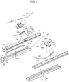
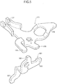
- FIG. 1 being a perspective view showing an inventive portion of this embodiment
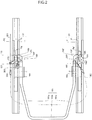
- Fig. 2 being a top view of a walk-in seat from which a seat is removed
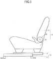
- Fig. 3 being a configurative view of the walk-in seat of the embodiment as viewed from a side.
- a seat 11 has a seat cushion 13 supporting a hip of a sitter, and a seatback 17 provided in a tiltable manner with respect to the seat cushion 13 via a reclining mechanism 15 to support the back of the sitter.
- 1 and 1' are first and second lower rails provided in parallel on a floor F.
- the first and second lower rails 1 and 1' are movably engaged with first and second upper rails 5 and 5' being provided with the seat cushion 13 of the seat 11 thereon, respectively.
- the first lower rail 1 and the first upper rail 5 configure a first seat track 21.
- the second lower rail 1' and the second upper rail 5' configure a second seat track 23.
- the first upper rail 5 has a first locking mechanism 100 thereon for prohibiting movement of the first upper rail 5.
- the second upper rail 5' has a second locking mechanism 100' thereon for prohibiting movement of the second upper rail 5'.
- the first upper rail 5 has a memory mechanism 300 thereon.
- first seat track 21 and the second seat track 23 have the same configuration, description is made only on the first seat track 21, and description of the second seat track 23 is omitted.
- a sectional configuration of the first lower rail 1 includes a horizontally disposed base portion 1a; a first sidewall portion 1b that is bent from one end of the base portion 1a, and extends upward; a second sidewall portion 1c that is bent from the other end of the base portion 1a, and extends upward; a first top portion 1d that is bent from an upper end of the first sidewall portion 1b, and extends toward the second sidewall portion 1c approximately parallel to the base portion 1a; a second top portion 1e that is bent from an upper end of the second sidewall portion 1c, and extends toward the first sidewall portion 1b approximately parallel to the base portion 1a; a first trailing portion 1f that is bent from the other end of the first top portion 1d toward the base portion 1a, and is shorter than the first sidewall portion 1b; and a second trailing portion 1g that is bent from the other end of
- the first upper rail 5 includes a top portion 5a provided approximately parallel to the base portion 1a of the first lower rail 1; a first sidewall portion 5b that is bent from one end of the top portion 5a, and extends into the first lower rail 1 via a space between the first trailing portion 1f and the second trailing portion 1g of the first lower rail 1; a second sidewall portion 5c that is bent from the other end of the top portion 5a, and extends into the first lower rail 1 via a space between the first trailing portion 1f and the second trailing portion 1g of the first lower rail 1; a first spring-up portion 5d that extends from a lower end of the first sidewall portion 5b into a space formed by the first sidewall portion 1b, the first top portion 1d, and the first trailing portion 1f of the first lower rail 1; and a second spring-up portion 5e that extends from a lower end of the second sidewall portion 5c into a space formed by the second sidewall portion 1c, the second top portion 1e, and the second
- the first trailing portion 1f and the second trailing portion 1g of the first lower rail 1 have a plurality of holes 1h and 1i along a longitudinal direction respectively.
- the second sidewall portion 5c and the second spring-up portion 5e in a range of a cutout hole 5g of the first upper rail 5 have holes 5h and 5i that may face the holes 1i of the first lower rail 1 respectively.
- first locking mechanism 100 and the second locking mechanism 100' are approximately the same, description is largely made on the first locking mechanism 100.
- the same portions as those of the first locking mechanism 100 are marked with the same symbols with a dash, and only different portions are described.
- a loop handle 151 is disposed between the first and second seat tracks 21 and 23.
- the loop handle 151 has an approximately U shape including a first side portion 151a along the first seat track 21, a forehead 151b along a forehead of the seat cushion 13, and a second side portion 151c along the second seat track 23.
- a loop handle support bracket 161 is provided on the top portion 5a of the first upper rail 5 of the first seat track 21.
- a loop handle support bracket 163 is provided on the top portion 5a' of the second upper rail 5' of the second seat track 23.
- the first side portion 151a of the loop handle 151 is provided on the loop handle support bracket 161, and rotatable about an axis C (axis approximately perpendicular to a movement direction of the first upper rail 5 on a plane parallel to the base portion 1a of the first lower rail 1).
- the second side portion 151c is provided on the loop handle support bracket 163, and rotatable about an axis C' (axis approximately perpendicular to a movement direction of the second upper rail 5' on a plane parallel to a base portion 1a' of the second lower rail 1').
- a shaft 101 along a longitudinal direction of the first upper rail 5 is rotatably provided in the cutout hole 5g formed from the top portion 5a to the second sidewall portion 5c of the first upper rail 5. Furthermore, a locking lever 103 attached to the shaft 101 is disposed in the cutout hole 5g.
- the locking lever 103 has three rotational ends.
- the first rotational end corresponds to locking teeth 105 that are located within the first upper rail 5, and engaged with the holes 1i of the first lower rail 1 via the holes 5h of the first upper rail 5, and furthermore, engaged with the holes 5i of the first upper rail 5.
- the locking lever 103 is biased in a direction (locking direction), in which the locking teeth 105 are engaged with the holes 1i of the first lower rail 1, by not-shown biasing means (spring) engaged with the first upper rail 5 at one end, and engaged with the locking lever 103 at the other end.
- the second rotational end corresponds to a loop handle attachment 107.
- the loop handle attachment 107 extends out of the first upper rail 5 from the cutout hole 5g toward the second seat track 23.
- the loop handle attachment 107 of the locking lever 103 of the first locking mechanism 100 is attached to a back portion of the mechanism 100 with respect to the axis C of the first side portion 151a of the loop handle 151, and a loop handle attachment 107' of a locking lever 103' of the second locking mechanism 100' is attached to a back portion of the mechanism 100' with respect to the axis C' of the second side portion 151c of the loop handle 151.
- the locking lever 103 of the first locking mechanism 100 and the locking lever 103' of the second locking mechanism 100' operate such that each of the locking teeth 105 and 105' moves in a direction away from each of the holes 1i of the first lower rail 1 and the holes 1i' of the second lower rail 1' (unlocking direction) against biasing force of the not-shown biasing means.
- the third rotational end corresponds to a control lever abutment portion 109 to be abutted with a control lever described later.
- Fig. 5 is an enlarged perspective view of a first control lever and a memory plate.
- a first control lever 171 is rotatably attached by a pin 173 to the top portion 5a near the cutout hole 5g of the first upper rail 5.
- the first control lever 171 has a locking lever abutment portion 175 that may abut on the control lever abutment portion 109 of the locking lever 103, and pushes the portion 109 in an abutment direction after abutting thereon so as to rotate the locking lever 103 in an unlocking direction.
- the first control lever 171 is biased in a direction in which the locking lever abutment portion 175 is separated from the control lever abutment portion 109 of the locking lever 103 (an arrow D direction in Fig. 1 ) by not-shown biasing means (spring) engaged with the first upper rail 5 at one end, and engaged with the first control lever 171 at the other end.
- biasing means spring
- a second control lever 181 is rotatably attached by a pin 183 to a top portion 5a' near a cutout hole 5g' of the second upper rail 5'.
- the second control lever 181 has a locking lever abutment portion 185 that may abut on a control lever abutment portion 109' of the locking lever 103' , and pushes the portion 109' in an abutment direction after abutting thereon so as to rotate the locking lever 103' in an unlocking direction.
- the second control lever 181 is biased in a direction in which the locking lever abutment portion 185 is separated from the control lever abutment portion 109' of the locking lever 103' (an arrow D direction in Fig. 1 ) by not-shown biasing means (spring) engaged with the second upper rail 5' at one end, and engaged with the second control lever 181 at the other end.
- a cable 201 is provided from the seatback 17 of the seat 11 to the second control lever 181 of the second lock mechanism 100' side via the first control lever 171 on a first lock mechanism 100 side.
- the cable 201 extends forward from the seatback 17 along the first seat track 21.
- One end of the cable 201 is latched on a point other than a rotational center of the seatback 17, so that when the seatback 17 is tilted forward, the cable 201 is drawn.
- a middle portion of the cable 201 is latched on a cable latching portion 177 of the first control lever 171 on the first locking mechanism 100 side.
- the cable 201 extends backward along the second seat track 23 through the forehead of the seat 11.
- the other end of the cable 201 is latched on a cable latching portion 187 of the second control lever 181.
- the cable 201 is divided into first cable means FC extending from the seatback 17 to the first control lever 171, and second cable means SC extending from the first control lever 171 to the second control lever 181. Furthermore, in the embodiment, an outer casing 203 inserted with the cable 201 is provided in a cable portion, which corresponds to the second cable means SC, between the first control lever 171 and the second control lever 181.
- the locking lever abutment portion 185 of the second control lever 181 abuts on the control lever abutment portion 109' of the locking lever 103', and pushes the portion 109' in the abutment direction, so that the locking lever 103' is rotated in the unlocking direction.
- a cancel lever 301 is rotatably provided via a not-shown bracket on the top portion 5a of the first upper rail 5 adjacently to the first control lever 171.
- a rotational plane of the cancel lever 301 is along a movement direction of the first upper rail 5, and perpendicular to a rotational plane of the first control lever 171.
- the cancel lever 301 has a first control lever abutment portion 303 that may abut on the first cancel lever abutment portion 179 of the first control lever 171 in an unlocked state.
- the cancel lever 301 is prohibited from rotating in a locking direction.
- the cancel lever 301 further has a second control lever abutment portion 305 that may abut on the second cancel lever abutment portion 178 of the first control lever 171 in a locked state.
- the first control lever abutment portion 303 of the cancel lever 301 is prohibited from rotating in a direction of abutting on the first cancel lever abutment portion 179 of the first control lever 171.
- the cancel lever 301 is biased in a direction, in which the first control lever abutment portion 303 abuts on the first cancel lever abutment portion 179 of the first control lever 171, or the second control lever abutment portion 305 abuts on the second cancel lever abutment portion 178 of the first control lever 171, namely, biased in an arrow E direction in Fig. 5 by not-shown biasing means (spring) engaged with the first upper rail 5 at one end, and engaged with the cancel lever 301 at the other end.
- spring biasing means
- a memory plate 304 is disposed on the base portion 1a of the first lower rail 1 of the first seat track 21.
- the cancel lever 301 has a memory plate abutment portion 307 extending into the first upper rail 5 through a cutout hole 5j formed in the top portion 5a of the first upper rail 5 so as to be able to abut on a top of the memory plate 304.
- the memory plate 304 is provided from an approximately middle portion to a back portion in a longitudinal direction of the first lower rail 1.
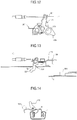
- Figs. 6 to 17 are top views for illustrating operation of each of the first control lever 171 and the cancel lever 301
- Figs. 7 , 10 , 13 and 16 are front views of Figs. 6 , 9 . 12 and 15 respectively
- Figs. 8 , 11 , 14 and 17 are section views for illustrating operation of a locking mechanism in respective states of Figs. 6 , 9 . 12 and 15 .
- the first control lever 171 connected to the cable 201 is positioned as shown in Fig. 6 .
- the second control lever abutment portion 305 of the cancel lever 301 abuts on the second cancel lever abutment portion 178 of the first control lever 171.
- the locking lever abutment portion 175 is positioned separately from the control lever abutment portion 109 of the locking lever 103
- the memory plate abutment portion 307 is positioned separately from the top of the memory plate 304
- the first control lever abutment portion 303 is positioned separately from the first cancel lever abutment portion 179 of the first control lever 171.
- Figs. 9 to 11 Description is made using Figs. 9 to 11 .
- the seatback 17 In the initial state as shown in Figs. 6 to 8 , the seatback 17 is tilted most forward while a sitter is not present.
- the cable 201 is greatly drawn, and thus the first control lever 171 rotates to a solid-line position shown in Fig. 9 .
- the first control lever 171 rotates in such a way, thereby the lock lever abutment portion 175 abuts on the control lever abutment portion 109 of the locking lever 103, and successively pushes the locking lever 103. Accordingly, the first locking mechanism 100 is unlocked.
- Such drawing of the cable 201 causes even rotation of the second control lever 181, unlocking the second locking mechanism 100'.
- the second cancel lever abutment portion 178 is separated from the second control lever abutment portion 305 of the cancel lever 301.
- the cancel lever 301 rotates in the arrow E direction in Fig. 5 until the memory plate abutment portion 307 abuts on the top of the memory plate 304.
- the first control lever abutment portion 303 is still separated from the first cancel lever abutment portion 179 of the first control lever 171 while the portion 303 is close to the portion 179.
- Figs. 12 to 14 Description is made using Figs. 12 to 14 .
- the seat 11 is moved forward in the state shown in Figs. 9 to 11 .
- the seat 11 is biased forward by not-shown biasing means latched on a floor side at one end, and latched on a seat 11 side at the other end.
- the seat 11 may be manually advanced.
- the memory plate abutment portion 307 of the cancel lever 301 is separated from the memory plate 304.
- the cancel lever 301 further rotates, so that the first control lever abutment portion 303 abuts on the first cancel lever abutment portion 179 of the first control lever 171. Therefore, the locking lever abutment portion 175 of the first control lever 171 is prohibited from being separated from the control lever abutment portion 109 of the locking lever 103. That is, the first locking mechanism 100 and the second locking mechanism 100' connected to the mechanism 100 by the cable 201 are kept to be unlocked.
- Figs. 15 to 17 Description is made using Figs. 15 to 17 .
- the seat 11 is moved back in the state shown in Figs. 12 to 14 .
- the memory plate abutment portion 307 of the cancel lever 301 gets on the top of the memory plate 304, and thus rotates to a solid line position in the figure. That is, the cancel lever 301 is returned into the state shown in Fig. 7 , and therefore becomes rotatable.
- the first control lever 171 rotates to a solid line position, and the first locking mechanism 100 is thus locked.
- the second control lever 181 rotates, and the second locking mechanism 100' is thus locked.
Landscapes
- Engineering & Computer Science (AREA)
- Aviation & Aerospace Engineering (AREA)
- Transportation (AREA)
- Mechanical Engineering (AREA)
- Seats For Vehicles (AREA)
Claims (2)
- Ein Einsteigsitz mit:einem Sitz (11) mit einem Sitzpolster (13) zum Stützen einer Hüfte einer/eines Sitzenden und mit einem Sitzrücken (17), der in einer schwenkbaren Weise bezüglich des Sitzpolsters (13) zum Stützen des Rückens der/des Sitzenden vorgesehen ist,einer ersten Sitzschiene (21) mit einer ersten unteren Schiene (1), die an einer Bodenseite vorgesehen ist, und einer ersten oberen Schiene (5), die beweglich mit der ersten unteren Schiene (1) in Eingriff ist und mit dem Sitzpolster (13) des Sitzes (11) darauf vorgesehen ist,einer zweiten Sitzschiene (23), die parallel zu der ersten Sitzschiene (21) vorgesehen ist, wobei die zweite Sitzschiene (23) eine zweite untere Schiene (1'), die an der Bodenseite vorgesehen ist, und eine zweite obere Schiene (5'), die beweglich mit der zweiten unteren Schiene (1') in Eingriff ist und mit dem Sitzpolster (13) des Sitzes (11) darauf versehen ist, aufweist,einem ersten Verriegelungsmechanismus (100), der an der ersten Sitzschiene (21) vorgesehen ist, um eine Bewegung der ersten oberen Schiene (5) bezüglich der ersten unteren Schiene (1) zu verhindern,einem ersten Steuerhebel (171), der drehbar an der ersten oberen Schiene (5) vorgesehen ist, um den ersten Verriegelungsmechanismus (100) zu entriegeln,einem zweiten Verriegelungsmechanismus (100'), der an der zweiten Sitzschiene (23) vorgesehen ist, um eine Bewegung der zweiten oberen Schiene (5') bezüglich der zweiten unteren Schiene (1') zu verhindern,einem zweiten Steuerhebel (181), der drehbar an der zweiten oberen Schiene (5') vorgesehen ist, um den zweiten Verriegelungsmechanismus (100') zu entriegeln,einem Speichermechanismus (300), der an der ersten Sitzschiene (21) vorgesehen ist, wobei der Speichermechanismus (300) den ersten Steuerhebel (171) so hält, dass, wenn die erste obere Schiene (5) sich zwischen einer Mittelposition und einer vordersten Position bei am weitesten nach vorne geneigtem Sitzrücken (17) befindet, der erste Verriegelungsmechanismus (100) entriegelt ist, undeinem ersten Kabelmittel (FC), das an dem Sitzrücken (17) an einem Ende angebracht ist und das an dem ersten Steuerhebel (171) an dem anderen Ende angebracht ist, wobei das erste Kabelmittel (FC) angeordnet ist, um so zu wirken, dass, wenn der Sitzrücken (17) des Sitzes (11) zu einer am weitesten nach vorne befindlichen Position geneigt ist, das erste Kabelmittel (FC) den ersten Steuerhebel (171) zum Entriegeln des ersten Verriegelungsmechanismus (100) antreibt,dadurch gekennzeichnet, dassein zweites Kabelmittel (SC) an dem ersten Steuerhebel (171) an einem Ende angebracht ist und an dem zweiten Steuerhebel (181) an dem anderen Ende angebracht ist, wobei das zweite Kabelmittel (SC) angeordnet ist, um eine Betätigung des ersten Steuerhebels (171) auf den zweiten Steuerhebel (181) zu übertragen, dassein durchgehendes einzelnes Kabel (201) vorgesehen ist, wobei das Kabel (201) an dem Sitzrücken (17) an einem Ende angebracht ist, an dem ersten Steuerhebel (171) an einem Mittelabschnitt angebracht ist, und an dem zweiten Steuerhebel (181) an dem anderen Ende angebracht ist, und dassein Abschnitt des Kabels (201) von dem Sitzrücken (17) zu dem ersten Steuerhebel (171) als das erste Kabelmittel (FC) ausgebildet ist, und ein Abschnitt des Kabels (201) von dem ersten Steuerhebel (171) zu dem zweiten Steuerhebel (181) als das zweite Kabelmittel (SC) ausgebildet ist.
- Der Einsteigsitz gemäß Anspruch 1, ferner mit einem äußeren Gehäuse (203), in das das Kabel (201) eingesetzt ist und das in einem Kabelabschnitt vorgesehen ist, der dem zweiten Kabelmittel (SC) entspricht.
Applications Claiming Priority (2)
| Application Number | Priority Date | Filing Date | Title |
|---|---|---|---|
| JP2007233690A JP5203658B2 (ja) | 2007-09-10 | 2007-09-10 | ウォークインシート |
| PCT/JP2008/066048 WO2009034921A1 (ja) | 2007-09-10 | 2008-09-05 | ウォークインシート |
Publications (3)
| Publication Number | Publication Date |
|---|---|
| EP2184200A1 EP2184200A1 (de) | 2010-05-12 |
| EP2184200A4 EP2184200A4 (de) | 2015-04-22 |
| EP2184200B1 true EP2184200B1 (de) | 2018-06-06 |
Family
ID=40451929
Family Applications (1)
| Application Number | Title | Priority Date | Filing Date |
|---|---|---|---|
| EP08829973.0A Not-in-force EP2184200B1 (de) | 2007-09-10 | 2008-09-05 | Begehbarer sitz |
Country Status (5)
| Country | Link |
|---|---|
| US (1) | US8408649B2 (de) |
| EP (1) | EP2184200B1 (de) |
| JP (1) | JP5203658B2 (de) |
| AU (1) | AU2008298387B2 (de) |
| WO (1) | WO2009034921A1 (de) |
Families Citing this family (10)
| Publication number | Priority date | Publication date | Assignee | Title |
|---|---|---|---|---|
| DE102007042595B4 (de) * | 2007-09-07 | 2015-06-25 | Johnson Controls Gmbh | Verstelleinrichtung zur Längsverstellung einer Kraftfahrzeugkomponente |
| JP6140499B2 (ja) * | 2013-03-27 | 2017-05-31 | テイ・エス テック株式会社 | 乗物用駆動機構 |
| JP6089975B2 (ja) | 2013-05-30 | 2017-03-08 | アイシン精機株式会社 | 車両用シートスライド装置 |
| KR101500211B1 (ko) * | 2013-12-03 | 2015-03-06 | 현대자동차주식회사 | 워크인 메모리 기능을 가지는 차량용 시트레일 장치 |
| JP6237304B2 (ja) | 2014-02-12 | 2017-11-29 | アイシン精機株式会社 | 車両用シートスライド装置 |
| JP6623911B2 (ja) * | 2016-04-11 | 2019-12-25 | トヨタ紡織株式会社 | 乗物用シート |
| US10538177B2 (en) * | 2016-10-18 | 2020-01-21 | Magna Seating Inc. | Power return for seat adjuster with easy-entry |
| JP6383047B2 (ja) * | 2017-05-01 | 2018-08-29 | テイ・エス テック株式会社 | 乗物用駆動機構 |
| JP7053221B2 (ja) * | 2017-11-08 | 2022-04-12 | シロキ工業株式会社 | 車両シートのスライド装置 |
| JP7111996B2 (ja) * | 2020-09-24 | 2022-08-03 | テイ・エス テック株式会社 | 乗物用駆動機構 |
Family Cites Families (23)
| Publication number | Priority date | Publication date | Assignee | Title |
|---|---|---|---|---|
| JPS60177267A (ja) | 1984-02-23 | 1985-09-11 | Shimadzu Corp | 自動分析装置 |
| CA1246430A (en) * | 1985-06-18 | 1988-12-13 | Dukecal J. Harding | Seat assembly |
| US4666208A (en) * | 1985-09-11 | 1987-05-19 | Arakawa Shatai Kogyo Kabushiki Kaisha | Walk-in mechanism associated with seat track structure |
| JPS6284536A (ja) | 1985-10-07 | 1987-04-18 | Nec Corp | 半導体装置の製造方法 |
| JPH0346971Y2 (de) * | 1985-11-18 | 1991-10-04 | ||
| JPH01150392A (ja) | 1987-12-07 | 1989-06-13 | Nec Corp | 電子装置の誤動作防止回路 |
| JPH0630547Y2 (ja) * | 1989-06-22 | 1994-08-17 | 株式会社大井製作所 | 車両用シートのウォークイン装置 |
| GB8917633D0 (en) * | 1989-08-02 | 1989-09-20 | Ti Cox Ltd | Improvements in vehicle seat slide mechanisms |
| JPH078300Y2 (ja) * | 1989-12-26 | 1995-03-01 | トヨタ自動車株式会社 | 車両用シートトラック |
| US5137331A (en) * | 1990-11-30 | 1992-08-11 | Magna International Inc. | Seat track assembly with mechanical memory |
| CA2097776C (en) * | 1993-06-04 | 1998-04-14 | Daniel Hughes | Vehicle seat track assembly |
| DE19510618A1 (de) * | 1994-05-19 | 1995-11-23 | Hammerstein Gmbh C Rob | Kraftfahrzeugsitz, der im vorgeklappten Zustand der Rückenlehne längsverschiebbar ist |
| JP3660420B2 (ja) * | 1996-04-08 | 2005-06-15 | シロキ工業株式会社 | シートスライド装置 |
| JPH09315190A (ja) * | 1996-05-30 | 1997-12-09 | Oi Seisakusho Co Ltd | ウォークインシートスライド装置 |
| US5855349A (en) * | 1997-06-16 | 1999-01-05 | General Motors Corporation | Easy entry seat adjuster assembly with position memory and improved seat return hold open means |
| US6102478A (en) * | 1998-01-16 | 2000-08-15 | Lear Corporation | Vehicle seat slide mechanism |
| FR2777836B1 (fr) * | 1998-04-23 | 2000-07-21 | Faure Bertrand Equipements Sa | Glissiere pour siege de vehicule, et siege comportant une telle glissiere |
| JPH11321404A (ja) | 1998-05-12 | 1999-11-24 | Shiroki Corp | シートスライド装置 |
| JP3634628B2 (ja) | 1998-06-22 | 2005-03-30 | ジョンソン コントロールズ オートモーティブ システムズ株式会社 | 自動車シートのウォークイン装置 |
| JP4120078B2 (ja) * | 1998-12-25 | 2008-07-16 | アイシン精機株式会社 | 車両シートのウォークイン装置 |
| US7025419B2 (en) * | 2003-05-12 | 2006-04-11 | Shiroki Corporation | Seat mechanism for vehicle |
| DE102005039540B4 (de) * | 2005-02-11 | 2018-02-08 | Adient Luxembourg Holding S.à.r.l. | Vorverlagerbarer Fahrzeugsitz mit einem Untergestell und einer vorklappbaren Rückenlehne |
| US7556315B2 (en) * | 2006-03-31 | 2009-07-07 | Lear Corporation | Latch actuator system |
-
2007
- 2007-09-10 JP JP2007233690A patent/JP5203658B2/ja not_active Expired - Fee Related
-
2008
- 2008-09-05 EP EP08829973.0A patent/EP2184200B1/de not_active Not-in-force
- 2008-09-05 US US12/673,093 patent/US8408649B2/en not_active Expired - Fee Related
- 2008-09-05 WO PCT/JP2008/066048 patent/WO2009034921A1/ja not_active Ceased
- 2008-09-05 AU AU2008298387A patent/AU2008298387B2/en not_active Ceased
Non-Patent Citations (1)
| Title |
|---|
| None * |
Also Published As
| Publication number | Publication date |
|---|---|
| JP5203658B2 (ja) | 2013-06-05 |
| WO2009034921A1 (ja) | 2009-03-19 |
| EP2184200A1 (de) | 2010-05-12 |
| AU2008298387A1 (en) | 2009-03-19 |
| US8408649B2 (en) | 2013-04-02 |
| EP2184200A4 (de) | 2015-04-22 |
| AU2008298387B2 (en) | 2012-09-06 |
| US20110298264A1 (en) | 2011-12-08 |
| JP2009062006A (ja) | 2009-03-26 |
Similar Documents
| Publication | Publication Date | Title |
|---|---|---|
| EP2184200B1 (de) | Begehbarer sitz | |
| US9731630B2 (en) | Seat slide device | |
| US7828382B2 (en) | Vehicle seat having an operation lever arrangement structure | |
| EP1601549B1 (de) | Sitzvorrichtung mit rücklehnenverriegelung | |
| EP4037932B1 (de) | Sitzanordnung mit rücklaufsperrelement | |
| US9296318B2 (en) | Vehicle seat | |
| JP5109543B2 (ja) | 乗物用シート | |
| CN101084134A (zh) | 汽车座靠背倾斜器和组合件 | |
| US7484808B2 (en) | Vision improving system for a head restraint | |
| EP3902703B1 (de) | Sitzanordnung zum verstauen am boden | |
| JP2005289228A (ja) | 車両用回転・スライド式シート | |
| CN115916585A (zh) | 具有超控状态的座椅组件 | |
| JP3942084B2 (ja) | 車両用シート | |
| JP3361425B2 (ja) | 車両用シートの収納構造 | |
| CN105764745A (zh) | 用于车辆的可收起式座椅 | |
| JP4060730B2 (ja) | 格納シート | |
| JPH11208325A (ja) | ウォークイン機構付きシートリクライニング装置 | |
| JP4047048B2 (ja) | シート | |
| JP2001001808A (ja) | シートスライド装置のロック機構 | |
| CN109421553B (zh) | 车辆用座椅装置 | |
| JP3630507B2 (ja) | シート | |
| JP5806045B2 (ja) | シート | |
| EP1241044B1 (de) | Sitzstruktur für ein Fahrzeug | |
| JP2001001809A (ja) | シートスライド装置のロック機構 | |
| JP3364108B2 (ja) | 車両用シートのロック装置 |
Legal Events
| Date | Code | Title | Description |
|---|---|---|---|
| PUAI | Public reference made under article 153(3) epc to a published international application that has entered the european phase |
Free format text: ORIGINAL CODE: 0009012 |
|
| 17P | Request for examination filed |
Effective date: 20100202 |
|
| AK | Designated contracting states |
Kind code of ref document: A1 Designated state(s): AT BE BG CH CY CZ DE DK EE ES FI FR GB GR HR HU IE IS IT LI LT LU LV MC MT NL NO PL PT RO SE SI SK TR |
|
| AX | Request for extension of the european patent |
Extension state: AL BA MK RS |
|
| DAX | Request for extension of the european patent (deleted) | ||
| RA4 | Supplementary search report drawn up and despatched (corrected) |
Effective date: 20150319 |
|
| RIC1 | Information provided on ipc code assigned before grant |
Ipc: B60N 2/20 20060101ALI20150313BHEP Ipc: B60N 2/08 20060101AFI20150313BHEP Ipc: B60N 2/12 20060101ALI20150313BHEP Ipc: B60N 2/07 20060101ALI20150313BHEP |
|
| GRAP | Despatch of communication of intention to grant a patent |
Free format text: ORIGINAL CODE: EPIDOSNIGR1 |
|
| INTG | Intention to grant announced |
Effective date: 20180117 |
|
| GRAS | Grant fee paid |
Free format text: ORIGINAL CODE: EPIDOSNIGR3 |
|
| GRAA | (expected) grant |
Free format text: ORIGINAL CODE: 0009210 |
|
| AK | Designated contracting states |
Kind code of ref document: B1 Designated state(s): AT BE BG CH CY CZ DE DK EE ES FI FR GB GR HR HU IE IS IT LI LT LU LV MC MT NL NO PL PT RO SE SI SK TR |
|
| REG | Reference to a national code |
Ref country code: GB Ref legal event code: FG4D |
|
| REG | Reference to a national code |
Ref country code: CH Ref legal event code: EP Ref country code: AT Ref legal event code: REF Ref document number: 1005706 Country of ref document: AT Kind code of ref document: T Effective date: 20180615 |
|
| REG | Reference to a national code |
Ref country code: IE Ref legal event code: FG4D |
|
| REG | Reference to a national code |
Ref country code: DE Ref legal event code: R096 Ref document number: 602008055553 Country of ref document: DE |
|
| REG | Reference to a national code |
Ref country code: NL Ref legal event code: MP Effective date: 20180606 |
|
| REG | Reference to a national code |
Ref country code: LT Ref legal event code: MG4D |
|
| PG25 | Lapsed in a contracting state [announced via postgrant information from national office to epo] |
Ref country code: SE Free format text: LAPSE BECAUSE OF FAILURE TO SUBMIT A TRANSLATION OF THE DESCRIPTION OR TO PAY THE FEE WITHIN THE PRESCRIBED TIME-LIMIT Effective date: 20180606 Ref country code: CY Free format text: LAPSE BECAUSE OF FAILURE TO SUBMIT A TRANSLATION OF THE DESCRIPTION OR TO PAY THE FEE WITHIN THE PRESCRIBED TIME-LIMIT Effective date: 20180606 Ref country code: BG Free format text: LAPSE BECAUSE OF FAILURE TO SUBMIT A TRANSLATION OF THE DESCRIPTION OR TO PAY THE FEE WITHIN THE PRESCRIBED TIME-LIMIT Effective date: 20180906 Ref country code: FI Free format text: LAPSE BECAUSE OF FAILURE TO SUBMIT A TRANSLATION OF THE DESCRIPTION OR TO PAY THE FEE WITHIN THE PRESCRIBED TIME-LIMIT Effective date: 20180606 Ref country code: NO Free format text: LAPSE BECAUSE OF FAILURE TO SUBMIT A TRANSLATION OF THE DESCRIPTION OR TO PAY THE FEE WITHIN THE PRESCRIBED TIME-LIMIT Effective date: 20180906 Ref country code: LT Free format text: LAPSE BECAUSE OF FAILURE TO SUBMIT A TRANSLATION OF THE DESCRIPTION OR TO PAY THE FEE WITHIN THE PRESCRIBED TIME-LIMIT Effective date: 20180606 Ref country code: ES Free format text: LAPSE BECAUSE OF FAILURE TO SUBMIT A TRANSLATION OF THE DESCRIPTION OR TO PAY THE FEE WITHIN THE PRESCRIBED TIME-LIMIT Effective date: 20180606 |
|
| PGFP | Annual fee paid to national office [announced via postgrant information from national office to epo] |
Ref country code: DE Payment date: 20180821 Year of fee payment: 11 |
|
| PG25 | Lapsed in a contracting state [announced via postgrant information from national office to epo] |
Ref country code: GR Free format text: LAPSE BECAUSE OF FAILURE TO SUBMIT A TRANSLATION OF THE DESCRIPTION OR TO PAY THE FEE WITHIN THE PRESCRIBED TIME-LIMIT Effective date: 20180907 Ref country code: HR Free format text: LAPSE BECAUSE OF FAILURE TO SUBMIT A TRANSLATION OF THE DESCRIPTION OR TO PAY THE FEE WITHIN THE PRESCRIBED TIME-LIMIT Effective date: 20180606 Ref country code: LV Free format text: LAPSE BECAUSE OF FAILURE TO SUBMIT A TRANSLATION OF THE DESCRIPTION OR TO PAY THE FEE WITHIN THE PRESCRIBED TIME-LIMIT Effective date: 20180606 |
|
| PGFP | Annual fee paid to national office [announced via postgrant information from national office to epo] |
Ref country code: GB Payment date: 20180905 Year of fee payment: 11 |
|
| REG | Reference to a national code |
Ref country code: AT Ref legal event code: MK05 Ref document number: 1005706 Country of ref document: AT Kind code of ref document: T Effective date: 20180606 |
|
| PG25 | Lapsed in a contracting state [announced via postgrant information from national office to epo] |
Ref country code: NL Free format text: LAPSE BECAUSE OF FAILURE TO SUBMIT A TRANSLATION OF THE DESCRIPTION OR TO PAY THE FEE WITHIN THE PRESCRIBED TIME-LIMIT Effective date: 20180606 |
|
| PG25 | Lapsed in a contracting state [announced via postgrant information from national office to epo] |
Ref country code: CZ Free format text: LAPSE BECAUSE OF FAILURE TO SUBMIT A TRANSLATION OF THE DESCRIPTION OR TO PAY THE FEE WITHIN THE PRESCRIBED TIME-LIMIT Effective date: 20180606 Ref country code: RO Free format text: LAPSE BECAUSE OF FAILURE TO SUBMIT A TRANSLATION OF THE DESCRIPTION OR TO PAY THE FEE WITHIN THE PRESCRIBED TIME-LIMIT Effective date: 20180606 Ref country code: EE Free format text: LAPSE BECAUSE OF FAILURE TO SUBMIT A TRANSLATION OF THE DESCRIPTION OR TO PAY THE FEE WITHIN THE PRESCRIBED TIME-LIMIT Effective date: 20180606 Ref country code: PL Free format text: LAPSE BECAUSE OF FAILURE TO SUBMIT A TRANSLATION OF THE DESCRIPTION OR TO PAY THE FEE WITHIN THE PRESCRIBED TIME-LIMIT Effective date: 20180606 Ref country code: AT Free format text: LAPSE BECAUSE OF FAILURE TO SUBMIT A TRANSLATION OF THE DESCRIPTION OR TO PAY THE FEE WITHIN THE PRESCRIBED TIME-LIMIT Effective date: 20180606 Ref country code: IS Free format text: LAPSE BECAUSE OF FAILURE TO SUBMIT A TRANSLATION OF THE DESCRIPTION OR TO PAY THE FEE WITHIN THE PRESCRIBED TIME-LIMIT Effective date: 20181006 Ref country code: SK Free format text: LAPSE BECAUSE OF FAILURE TO SUBMIT A TRANSLATION OF THE DESCRIPTION OR TO PAY THE FEE WITHIN THE PRESCRIBED TIME-LIMIT Effective date: 20180606 |
|
| PG25 | Lapsed in a contracting state [announced via postgrant information from national office to epo] |
Ref country code: IT Free format text: LAPSE BECAUSE OF FAILURE TO SUBMIT A TRANSLATION OF THE DESCRIPTION OR TO PAY THE FEE WITHIN THE PRESCRIBED TIME-LIMIT Effective date: 20180606 |
|
| REG | Reference to a national code |
Ref country code: DE Ref legal event code: R097 Ref document number: 602008055553 Country of ref document: DE |
|
| PLBE | No opposition filed within time limit |
Free format text: ORIGINAL CODE: 0009261 |
|
| STAA | Information on the status of an ep patent application or granted ep patent |
Free format text: STATUS: NO OPPOSITION FILED WITHIN TIME LIMIT |
|
| PG25 | Lapsed in a contracting state [announced via postgrant information from national office to epo] |
Ref country code: MC Free format text: LAPSE BECAUSE OF FAILURE TO SUBMIT A TRANSLATION OF THE DESCRIPTION OR TO PAY THE FEE WITHIN THE PRESCRIBED TIME-LIMIT Effective date: 20180606 |
|
| REG | Reference to a national code |
Ref country code: CH Ref legal event code: PL |
|
| 26N | No opposition filed |
Effective date: 20190307 |
|
| PG25 | Lapsed in a contracting state [announced via postgrant information from national office to epo] |
Ref country code: SI Free format text: LAPSE BECAUSE OF FAILURE TO SUBMIT A TRANSLATION OF THE DESCRIPTION OR TO PAY THE FEE WITHIN THE PRESCRIBED TIME-LIMIT Effective date: 20180606 Ref country code: DK Free format text: LAPSE BECAUSE OF FAILURE TO SUBMIT A TRANSLATION OF THE DESCRIPTION OR TO PAY THE FEE WITHIN THE PRESCRIBED TIME-LIMIT Effective date: 20180606 |
|
| REG | Reference to a national code |
Ref country code: BE Ref legal event code: MM Effective date: 20180930 |
|
| REG | Reference to a national code |
Ref country code: IE Ref legal event code: MM4A |
|
| PG25 | Lapsed in a contracting state [announced via postgrant information from national office to epo] |
Ref country code: LU Free format text: LAPSE BECAUSE OF NON-PAYMENT OF DUE FEES Effective date: 20180905 |
|
| PG25 | Lapsed in a contracting state [announced via postgrant information from national office to epo] |
Ref country code: IE Free format text: LAPSE BECAUSE OF NON-PAYMENT OF DUE FEES Effective date: 20180905 |
|
| PG25 | Lapsed in a contracting state [announced via postgrant information from national office to epo] |
Ref country code: CH Free format text: LAPSE BECAUSE OF NON-PAYMENT OF DUE FEES Effective date: 20180930 Ref country code: BE Free format text: LAPSE BECAUSE OF NON-PAYMENT OF DUE FEES Effective date: 20180930 Ref country code: FR Free format text: LAPSE BECAUSE OF NON-PAYMENT OF DUE FEES Effective date: 20180930 Ref country code: LI Free format text: LAPSE BECAUSE OF NON-PAYMENT OF DUE FEES Effective date: 20180930 |
|
| PG25 | Lapsed in a contracting state [announced via postgrant information from national office to epo] |
Ref country code: MT Free format text: LAPSE BECAUSE OF NON-PAYMENT OF DUE FEES Effective date: 20180905 |
|
| PG25 | Lapsed in a contracting state [announced via postgrant information from national office to epo] |
Ref country code: TR Free format text: LAPSE BECAUSE OF FAILURE TO SUBMIT A TRANSLATION OF THE DESCRIPTION OR TO PAY THE FEE WITHIN THE PRESCRIBED TIME-LIMIT Effective date: 20180606 |
|
| REG | Reference to a national code |
Ref country code: DE Ref legal event code: R119 Ref document number: 602008055553 Country of ref document: DE |
|
| PG25 | Lapsed in a contracting state [announced via postgrant information from national office to epo] |
Ref country code: HU Free format text: LAPSE BECAUSE OF FAILURE TO SUBMIT A TRANSLATION OF THE DESCRIPTION OR TO PAY THE FEE WITHIN THE PRESCRIBED TIME-LIMIT; INVALID AB INITIO Effective date: 20080905 Ref country code: PT Free format text: LAPSE BECAUSE OF FAILURE TO SUBMIT A TRANSLATION OF THE DESCRIPTION OR TO PAY THE FEE WITHIN THE PRESCRIBED TIME-LIMIT Effective date: 20180606 |
|
| PG25 | Lapsed in a contracting state [announced via postgrant information from national office to epo] |
Ref country code: DE Free format text: LAPSE BECAUSE OF NON-PAYMENT OF DUE FEES Effective date: 20200401 |
|
| GBPC | Gb: european patent ceased through non-payment of renewal fee |
Effective date: 20190905 |
|
| PG25 | Lapsed in a contracting state [announced via postgrant information from national office to epo] |
Ref country code: GB Free format text: LAPSE BECAUSE OF NON-PAYMENT OF DUE FEES Effective date: 20190905 |